1
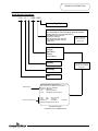
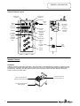
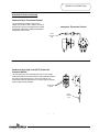
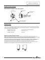
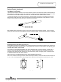
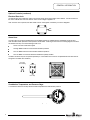
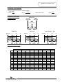
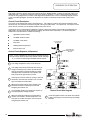
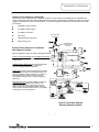
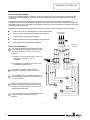
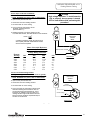
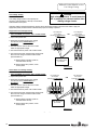
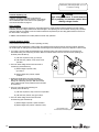
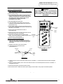
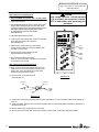
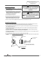
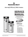
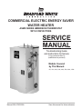
COMMERCIAL ELECTRIC ENERGY SAVER
WATER HEATER
ASME SERIES IMMERSION THERMOSTAT
WITH CONTACTORS
SERVICE
MANUAL
Troubleshooting Guide
and Instructions for Service
(To be performed ONLY by
qualified service providers)
Models Covered
by This Manual:
6A, 12A, 20A, 30A, 40A, 50A, 80A, 120A
Manual 238-47202-00A
Save this manual for future reference
ASME Series
Commercial Electric Water Heaters
Table of Contents
Page
Service Procedure
Introduction ………………………………………………………………………. 2
---
Tools……………………………………………………………………………… 2
---
General Information ……………………………………………………………… 3
---
Sequence of Operation …………………………………………………………… 10
---
Troubleshooting ………………………………………………………………….. 13
---
Heating Element Testing ……………..................................................................... 15
ACE-I
Line Voltage Testing………………...…………………………………………… 16
ACE-II
Fuse Testing…......................................................................................................... 17
ACE-III
High Limit (ECO) Testing……………………………………………………..…. 18
ACE-IV
Immersion Thermostat Operation Testing………................................................... 19
ACE-V
Contactor Operation Testing……………………………………………………… 20
ACE-VI
Immersion Thermostat Removal and Replacement…………….………………… 21
ACE-VII
High Limit (ECO) Removal and Replacement……………..…………………….. 22
ACE-VIII
Heating Element Removal and Replacement …………………………………….. 23
ACE-IX
Anode Inspection and Replacement ……………………………………………… 24
ACE-X
Generic Parts List ………………………………………………………………… 25
---
Glossary of Terms…………………………………………………………………. 26
---
Introduction
This service manual is designed to aid service and maintenance professionals on the function, proper diagnosis and repair of
Bradford White Commercial Electric Water Heaters.
The text and illustrations in this manual provide step by step instructions to facilitate proper operation and troubleshooting
procedures. Contact the Bradford White Technical Support Group immediately if diagnosis can not be made using the
methods described in this service manual.
Tools
- Multi Meter.
- 2-1/8" Deep Well Socket.
- 1-1/16" Deep Well Socket.
- ¼" Nut Driver.
- Phillips Head Screw Driver.
- Common Screw driver.
- Thermometer.
- Drain Hose.
- Other Hand Tools: Pipe Wrench, Channel Locks, Pliers (common & needle nose), Wire cutters, Wire Strippers,
Allen Wrench Set, Flash Light.
Page 2
2
GENERAL INFORMATION
Model Number Breakdown
120A - 24 - 3 - 108B - BBG
Pressure Gage Option.
Control Circuit Option Code.
Any combination of the following optional controls:
- Heating Element Time Delay Sequencing.
- Low Water Power Interrupt.
- Panel Door Interlock
- High Pressure Power Interrupt
- Low Pressure Power Interrupt
- Alarm Horn
NOTE: Code “AA”
denotes no optional
controls used.
Power Circuit Code.
- Voltage
- kW Rating
- Phase
- Amp Rating
Warranty
In the Field, this information
is obtained from the heaters
rating plate
kW Rating
Tank
Model Number
Electrical Characteristics
BRADFORD WHITE CORPORATION
200 LAFAYETTE ST. MIDDLEVILLE MI 49333
Model No: 120A-24-3-108B-BBG
Serial No: ZB2564812
Cap.
120(gal.)/454.2(liters)
Press:
Test 300(psi), Working 150(psi)
Volts
240
Max Temp 180°
Phase
Single
Amps 100
kW Each 6
Total kW 24
Wattage Rating Based Upon 60 Hz
4 Elements
Typical Rating Plate
Located On Front Of Water Heater
Page 3
3
GENERAL INFORMATION
General Controls Layout
Control Circuit
Fuse Block
Control Circuit
Transformer
Terminal strip
Pressure
Gage
(optional)
Terminal
Block
Power Circuit
Fuse Blocks
Thermostat
Control
Contactors
Heating Element
Time Delay
Sequencers
(optional)
Low Water
Level Control
(optional)
High Pressure
Limit Switch
(optional)
Low Pressure
Limit Switch
(optional)
High Limit
Immersion Bulb
Thermostat
Immersion
Bulb
High Limit
(ECO)
Alarm
Horn Relay
(optional)
Alarm
Horn
(optional)
Heating
Element
Standard Controls
Contactor
Contactor operation is achieved by energizing a 120 volt operating coil located within the contactor in response to a call
for heat from the immersion thermostat. Upon a call for heat, one or more contactors will energize all heating elements
simultaneously. Optionally, time delay sequencers may be used to stage contactor activation thereby reducing the
inrush of current to the water heater.
Terminal connections of
contactor operating coil.
Terminal connections to the
fuse block and/or terminal block
Terminal connections to the
heating elements
Page 4
4
GENERAL INFORMATION
Standard Controls (continued)
Immersion Style Thermostat Control
The thermostat will complete control circuit
voltage upon a call for heat. Likewise, the control
will interrupt control circuit voltage when the water
temperature is sufficient to satisfy the adjustable
temperature limit of control.
Immersion Thermostat Control
Direct
Immersion
bulb
Immersion Style High Limit (ECO) Control for
Contactor Models
The high limit (ECO) control will interrupt control circuit voltage
causing the heater to shut down when the high temperature limit of
the control is reached (196°F±4°F). Once the cause for over
heated water has been determined, The control must be manually
reset to restore normal operation.
Manual Reset
Buttons
Direct
Immersion
bulb
Page 5
5
GENERAL INFORMATION
Standard Controls (continued)
Direct Immersion “Screw-in” Type Heating Element
2-1/8 Hex
Screw-in Flange
Terminal Block
Screw
Terminal Block
Zinc Plated Copper or
Incoloy Sheath
Element Rating Ink Stamped
on face of Terminal Block.
Optional Controls
Certain control components are available as “Optional“. When these optional components are installed with the water
heater, the control circuit wiring diagram accordingly will include these components. The optional equipment available
from the manufacturer includes the following:
-High Water Pressure Switch
-Heating Element Time Delay Sequencers
-Low Water Pressure Switch
-Electrical Door Lock
-Low Water Level Switch
-Alarm Horn
High and Low Water Pressure Controls-
These controls interrupt the electrical current to the contactor coil when the pressure settings are exceeded. The
operation and setting of these controls are described in the manual provided by the control manufacturer. This manual is
included with the water heater Installation and Operating Instruction manual provided with the water heater.
The pressure settings for these controls are adjustable. These controls are specified for use when the installation has
unique pressure requirements that must be safeguarded. Therefore, before adjusting the pressure values, it is
recommended that you consult the person responsible for the facility that the water heater is servicing.
The electrical connections are referenced in the Control Circuit Wiring Diagram and in the pressure control manual
provided by the control manufacturer. Refer to these instructions when servicing the controls.
Page 6
6
GENERAL INFORMATION
Optional Controls (continued)
Low Water Level Control-
This control will interrupt the electrical current to the contactor coil when a low water level condition is sensed inside the
water heater tank. When the low water level condition is corrected the control will automatically sense the new situation
and electrical current will again energize the contactor coil. Normal water heater operation will be resumed.
To remove the low water level control from the tank you must first loosen the control by un-threading it from the tank
fitting and then rotating the control until the arrow printed on the side of the hex fitting is pointing downward. This will
enable the float orientation to align itself with the opening in the tank-fitting.
When installed, refer to the direction of the arrow on the hex and insure that it is pointing upwards. If it is not pointing
upward, the control switch will not activate when the tank is refilled with water. Refer to illustration below for clarification.
Heating Element Time Delay Sequencers-
Heating element sequencers are available in order to stage the activation of the heating elements thereby, reducing the
inrush of electrical current to the water heater. The sequencers will control one or more contactor coils depending upon
the water heater voltage, phase, and KW.
One contactor will be energized immediately when there is heating demand, the second contactor, controlled with a
sequencer, will be activated approximately 20 seconds later, and the third contactor will be activated in another 20
seconds thereby, staging the three contactors over the 40 second time period. The staging occurs in a similar manner
for applications having more than three contactors.
Refer to the Control Circuit Wiring Diagram for the specific application being serviced.
Note: On the occasion of servicing the water heater where frequent restarts in a short time interval are encountered (i.e.
on, off, on, etc.), the timing sequences will not begin until the sequencers have experienced a time interval to reset.
Page 7
7
GENERAL INFORMATION
Optional Controls (continued)
Electrical Door lock-
An electrical door lock is offered in order to secure the access to the water heater control cabinet. This device will lock
the control cabinet door when the 120VAC control circuit voltage is applied to it.
Note: Once the door is opened, the water heater can be re-energized, if necessary, for service diagnosis.
Alarm HornThe Alarm Horn is an option specified when the installation desires an audible signal to immediately sound an alert
when the water heater operation is interrupted for certain faults. Referring to the control circuit wiring diagram, the alarm
will activate when any one of the following events occur:
The Hi-Limit control has been tripped
The High Water Pressure Control senses excessive pressure
The Low Water Pressure Control senses insufficient pressure
The Low Water Level Control senses an insufficient quantity of water
The alarm will sound only for the options specified (i.e. if a low water level control is not specified then the alarm will not
recognize a low water level condition).
Horn Relay
Internal Wiring
Horn Relay
Combination Temperature and Pressure GageA non-electrical device to visually reference water temperature and internal tank pressure.
Page 8
8
GENERAL INFORMATION
Commonly Used Formulas
(balanced 3 phase)
(Single phase)
Watts
Amps =
Amps =
Volts
Common Service Wire
Configurations
Watts
Ohms =
Watts = Amps x Volts
Volts x 1.732
2
Volts
Watts
240V 1Ph
BLACK
Ungrounded
GREEN
Grounding
RED
Ungrounded
240
120
120
208 3Ph
Neutral
A
480 3Ph/277 1Ph
240 3Ph
B
C
Neutral
A
B
C
Neutral
120
120
120
208
120
208
240
208
240
RED
RED
C
277
120
BLACK
B
277
120
RED
A
480
277
480
240
BLACK
RED
RED
480
BLACK
RED
Full Load Current Amps
240 Volt
600 Volt
277 Volt
380 Volt
415 Volt
kW
1 Ph
3 Ph
1 Ph
3 Ph
1 Ph
3 Ph
3 Ph
1 Ph
3 Ph
3
14.4
-
12.5
-
10.8
-
-
6.3
-
-
6
28.8
16.6
25.0
14.4
21.6
9.1
8.3
12.5
7.2
5.7
9
12
43.2
57.6
25.0
33.3
37.2
50.0
21.6
28.9
32.4
43.3
13.6
18.2
12.5
16.7
18.7
25.0
10.8
14.4
8.66
11.5
13.5
64.9
37.5
56.2
32.5
48.7
20.5
18.8
28.1
16.2
13.0
15
72.1
41.6
62.5
36.1
54.1
22.7
20.9
31.2
18.0
14.4
18
86.5
50.0
75.0
43.4
64.9
27.3
25.0
37.5
21.6
17.3
24
115.4
66.7
100.0
57.8
86.6
36.4
33.4
50.0
28.9
23.1
27
129.8
75.0
112.5
65.0
97.4
41.0
37.5
56.2
32.5
26.0
30
144.2
83.3
125.0
72.2
108.3
45.6
41.7
62.5
36.1
28.8
36
173.0
100.0
150.0
86.7
129.9
54.7
50.1
75.0
43.3
34.6
45
54
216.3
259.6
125.0
150.0
187.5
225.0
108.3
130.0
162.4
194.9
68.4
82.0
62.6
75.1
93.7
112.5
54.1
65.0
43.3
52.0
81
389.4
224.8
337.5
194.8
292.4
123.1
112.6
168.7
97.4
78.0
208 Volt
480 Volt
3 Ph
Page 9
9
SEQUENCE OF OPERATION
This water heater has two distinct electrical systems. One system, referred to as the “Control Circuit”, controls the
water heater operation, while the other system referred to as the “Power Circuit”, connects the electrical power to the
heating elements, The electrical contactors interconnect these two systems. In order to clearly illustrate the electrical
circuits, two wiring diagrams are provided. These diagrams are labeled as the “Control Circuit Wiring Diagram” and the
“Power Circuit Wiring Diagram” and they are attached to the surface of the panels inside the water heater control
cabinet.
Control Circuit Description-
The control circuit operates with 120VAC electrical service. This voltage is provide by the multi-tap transformer which
has the primary coil connected to the field wiring that is serving the water heater. The Transformer, Thermostat, Hi-Limit
control, and the Contactor Coil are always included in the Control Circuit.
Certain other control components are available as “Optional“. When these optional components are installed with the
water heater, the control circuit wiring diagram accordingly will include these components. The optional equipment
available from the manufacturer includes the following:
High Water Pressure Switch
Low Water Pressure Switch
Low Water Level Switch
Line voltage from
power circuit
Alarm Horn
Heating Element Sequencers
Electrical Door Lock
Appropriate line
voltage multi-tap
terminal
Control Circuit Sequence of OperationNOTE: To help understand the concept of the operating sequence,
the control circuit shown is without any optional controls. See page
11 For control circuit showing all available optional controls
1
Line voltage is applied to control circuit fuse block.
2
Line voltage continues to transformer with one leg of
voltage connecting to the common terminal and the
other leg connecting to the appropriate line voltage
multi-tap terminal. Transformer output (always 120
volts) continues to high limit (ECO) control.
3
4
5
6
Hi limit (ECO) control is closed so one leg of 120 volts
continues to one side of the contactor coil. The other
leg is connected to the thermostat.
When the thermostat calls for heat, contacts close
inside the thermostat completing the circuit and
energizing the contactor coil.
Control Circuit Wire Diagram
The energized contactor coil causes the contactor to
close energizing the heating elements.
When the temperature setting of the thermostat is
reached, the contacts in the thermostat open. This
interrupts current flow through the control circuit deenergizing the contactor coil.
7
Page 10
10
The de-energized contactor coil causes the contactor
to open, interrupting current flow through the Heating
elements.
SEQUENCE OF OPERATION
Control Circuit Sequence (Continued)-
Certain other control components are available as “Optional“. These controls are specified when the installation has
unique requirements that must be safeguarded. When these optional components are installed the control circuit wiring
diagram accordingly will include these components. The optional equipment available from the manufacturer includes
the following:
High Water Pressure Switch
Low Water Pressure Switch
Low Water Level Switch
Alarm Horn
Line voltage from
power circuit
Heating Element Sequencers
Electrical Door Lock
Appropriate line
voltage multi-tap
terminal
Control Circuit Sequence of Operation
with Optional ControlsSame as explained on page 10 with the following exceptions:
-Hi and Low Pressure Switch and Low Water Level Switch
when specified are always wired in series ahead of the
Hi-limit control.
-Heating Element Sequencers are wired in series with
contactor coils staging contactor activation at
intervals of approximately 20 seconds.
-Alarm Horn is wired in series ahead of the thermostat.
It monitors only the Hi and Low pressure switch, Low
water level Switch and the hi-limit (ECO). If either of
these switches open, power to the horn relay is
interrupted causing the relay to close sounding the
alarm horn.
-Electrical Door Lock is wired in parallel to secure the
access to the water heater control cabinet. This
device will lock the control cabinet door when the
120VAC control circuit voltage is applied. Once the
door is opened, the water heater can be re-energized,
if necessary, for service diagnosis.
Control Circuit Wire Diagram
Showing Optional Controls
Page 11
11
SEQUENCE OF OPERATION
Power Circuit Description-
The Power Circuit Wiring Diagram illustrates the electrical connections from the incoming power supply through the
contactors to the heating elements. The power circuits are available with internal circuit fusing and without internal
circuit fusing.
As it would be impractical to show all wired configurations in this service manual, a reference wiring diagram is
illustrated below to aid in the understanding of the power circuit operating sequence. Service providers must refer to the
water heaters power circuit wiring diagram attached to the inside panel of the control cabinet for the specific connections
of the water heater being serviced.
The power circuit components and supporting information that appear on the wiring diagram include the following:
Field wiring connection via terminal block or other connection point
Fuse block with amperage ratings displayed (when provided)
Line voltage from
service panel
Contactors with amperage ratings displayed
Electrical elements with voltage and wattage ratings displayed
Water heaters total amperage draw is displayed
Line voltage to
control circuit
Power Circuit Sequence1
Line voltage is applied across terminals of fuse block
or a terminal block. Line voltage continues down and
connects to terminals L1, L2 & L3 of one or more
contactors.
A) Contactor is open (no call for heat), so there is no
voltage across terminal T1, T2 & T3
of contactor.
B) The contactor is controlled by the control circuit
as explained on pages 10 & 11.
2
3
4
5
The control circuit senses a call for heat and
energizes the operating coil within the contactor.
The energized contactor coil causes the contactor to
close energizing the elements from terminals T1, T2
& T3 of the contactor.
When the temperature setting of the thermostat is
reached, the contacts in the thermostat open. This
interrupts current flow through the control circuit deenergizing the contactor coil.
The de-energized contactor coil causes the contactor
to open, interrupting current flow through the
elements.
Page 12
12
TROUBLESHOOTING
Most common cause for improper electric water heater operation can be linked to heating element
failure.
When troubleshooting an electric water heater with the incidence of “No Hot Water” or “Insufficient Amount of Hot
Water” It is always a good idea to check the heating elements first following the procedure on page 15.
Common Heating Element Failures Are:
1. Dry Firing. Elements may be partially submerged in water or most likely, completely exposed with no water
in the tank at all. In open air, an energized element (Dry Fired) will become completely inoperable within
seconds. In some cases sediment or lime build up around an element can eventually cause an air pocket,
resulting in a dry fired element. When element replacement is required, be sure tank is full of water prior to
energizing the water heater.
2. Grounded Element. In most cases, an element with a short circuit to ground will cause the circuit breaker in
the service panel to open or shut off. In some cases there may not be enough current draw for the circuit
breaker to open. This will allow the heating element to be in continuous operation resulting in over heated
water, limited only by the hi-limit (ECO) located in the control circuit. Repeated actuation of the
hi-limit usually is the result of a grounded heating element.
3. Sediment build up. Slow hot water recovery can usually be traced back to sediment or lime build up around
heating element. Sediment build up can also over time cause a dry fired element.
If an heating element is found to be inoperative, it must be replaced. Follow service procedure ACE-IX on page 23.
The illustration below shows a common “Screw-In” type heating element identifying certain features commonly referred
to throughout this manual.
2-1/8 Hex
Screw-in Flange
Terminal Block
Screw
Terminal Block
Zinc Plated Copper or
Incoloy Sheath
Element Rating Ink Stamped
on face of Terminal Block.
Typical Direct Immersion “Screw-In”
Type Heating Element
Page 13
13
TROUBLESHOOTING
Quick Step Plan to Hot Water
WARNING
High voltage exposure. Use caution when
making voltage checks to avoid hazard to
life or property.
1. STOP, DANGER! Turn power “OFF” to water heater.
2. Check all wire connections to insure they are snug
and corrosion free.
3. Reset high limit (ECO) (page 18).
4. Check for inoperative heating element (page 15).
5. Check line voltage (pg 16), and internal fuses (page 17).
6. Refer to table below if items 1 through 5 above do not correct problem.
SYMPTOM
PROBABLE CAUSE
1. No power to heater.
2. Blown water heater fuses.
3. Loose wire connections.
4. Inoperative heating element(s).
5. Inoperative thermostat.
6. Open ECO.
7. Inoperative contactor(s).
1.
2.
3.
4.
5.
6.
7.
Check circuit breakers at service panel.
Check water heater fuses.
Check all wire connections.
Check heating element(s).
Check thermostat operation.
Reset (check) ECO.
Check contactor operation.
2.
4.
5.
6.
7.
Not Enough Hot
Water
1. Inoperative heating element(s).
2. Thermostat set to low.
3. Inoperative thermostat.
4. Inoperative contactor(s).
5. Loose wire connection.
6. High demand period.
7. Undersized heater.
8. Very cold inlet water to heater.
9. Plumbing connections reversed.
1.
2.
3.
4.
5.
6.
7.
8.
9.
Check heating element(s).
Increase thermostat setting.
Check thermostat.
Check contactor operation.
Check all wire connection.
Reduce demand.
Replace with larger heater.
Temper water to heater.
Correct plumbing connections.
1. ACE-I, Page 15.
3. ACE-V, Page 19.
4. ACE-VI, Page 20.
Slow Hot Water
Recovery
1. Sediment or lime build up on element(s).
2. Loose wire connections.
3. Inoperative contactor(s).
4. Derated heating element installed.
1.
2.
3.
4.
Clean or replace heating elements.
Check all wire connections.
Check contactor operation.
Verify element voltage and wattage rating.
1. ACE-IX, Page 23.
3. ACE-VI, Page 20.
4. See page 6.
1. Grounded heating element(s).
2. Thermostat set to high.
3. Inoperative thermostat.
4. Inoperative ECO.
1.
2.
3.
4.
Check heating element(s).
Adjust thermostat to desired setting.
Check thermostat.
Check ECO.
1. ACE-I, Page 15.
3. ACE-V, Page 19.
4. ACE-IV, Page 18.
1. Lime formation on elements.
2. High or low line voltage.
1. Clean or replace heating elements.
2. Verify line voltage to heater.
1. ACE-IX, Page 23.
2. ACE-II, Page 16.
1. Low line voltage.
2. Debris between contactor plates.
3. Incorrect or defective operating coil.
4. Loose wire connections.
1.
2.
3.
4.
1. ACE-II, Page 16
No Hot Water
Over Heated
Water
Noisy (singing or
hissing) Elements
Noisy Contactor
Verify line voltage to heater
Replace contactor.
Replace contactor.
Check wire connections.
Page 14
14
SERVICE
PROCEDURE
CORRECTIVE ACTION
ACE-III, Page 17
ACE-I, Page 15.
ACE-V, Page 19.
ACE-IV, Page 18
ACE-VI, Page 20
SERVICE PROCEDURE ACE-I
Heating Element Testing
Test for Open or Burned Out Element.
1. STOP, DANGER! Turn power “OFF” to water heater.
2. Open control panel access door.
3. Disconnect wires from heating element.
DANGER
High voltage exposure. To avoid hazard to
Life or property, be sure power is turned
OFF to water heater while performing this
procedure.
4. Set multi-meter to “ohms” setting.
5. Touch probes of multi-meter to screw
terminals of heating element
(see illustration 1).
6. Reading should be 12.8 ohms (±6%) for a 240
volt, 4500 watt element, see table below for other elements.
NOTE
Disconnect
element
Wires
2
Ohms = Volts
Watts
A reading outside the range using the formula
above (±6%), indicates a bad element and the
element must be replaced.
Ohms of electrical Resistance
For commonly Used Elements
Element Screw Terminals
Voltage Rating of Element
Element
Wattage
208
240
480
600
2000
3000
4000
4500
5000
6000
9000
21.6
14.4
10.8
9.6
8.7
7.2
4.8
28.8
19.2
14.4
12.8
11.5
9.6
6.4
115.2
76.8
57.6
51.2
46.1
38.4
25.6
180
120
90
80
72
60
40
Illustration 1
Test For Grounded Heating Element
(damaged heating element with short circuit to ground).
NOTE
Disconnect
element
Wires
1. STOP, DANGER! Turn power “OFF” to water heater.
2. Open control panel access door.
3. Disconnect wires from heating element.
Element
Screw Terminal
4. Set multi-meter to “ohms” setting.
5. Touch one probe of multi-meter to either screw
terminal of heating element and the other on
the element flange (see illustration 2). There
should be no reading on the ohm meter. Any
reading indicates a grounded element and the
element must be replaced. Repeat this step for
the other screw terminal.
Element Flange
Illustration 2
Page 15
15
SERVICE PROCEDURE ACE-II
Line Voltage Testing
DANGER
High voltage exposure. To avoid hazard to
life or property use extreme caution when
making voltage checks .
Line Voltage Testing
Line voltage (single phase or three phase) will
connect to a terminal block or directly to a fuse block
located inside control panel.
Determine heaters voltage and phase by referring to the rating plate located on the front of the heater. Apply the
appropriate phase procedure below to determine if proper line voltage is present.
Single Phase Line Voltage Testing
1. STOP, DANGER! Turn power “OFF” to water heater.
2. Open control panel door.
Line voltage from
service panel
connected to Terminal block
of heater
Line voltage from
service panel
connected to Fuse block
of heater
OR
3. Determine connection point for line voltage
from service panel, terminal block or
fuse block
4. Set multi-meter to volts AC. Be sure to scale
meter for appropriate voltage.
5. Use caution and turn power “ON” to water heater.
6. Use caution and check voltage across top terminals
where service voltage connects to water heater.
(see illustration 3).
A) Rated voltage IS present, power to
the water heater is okay.
Check voltage across
top terminals.
B) Rated voltage NOT present, Check
service panel.
Illustration 3
Three Phase Line Voltage Testing
1. STOP, DANGER! Turn power “OFF” to water heater.
2. Open control panel door.
3. Determine connection point for line voltage
from service panel, terminal block or
fuse block
Line voltage from
service panel
connected to Terminal block
of heater
OR
Line voltage from
service panel
connected to Fuse block
of heater
4. Set multi-meter to volts AC. Be sure to scale
meter for appropriate voltage.
5. Use caution and turn power “ON” to water heater.
6. Use caution and check voltage across top terminals
where service voltage connects to water heater.
(see illustration 4).
A) Rated voltage IS present, power to
the water heater is okay.
Check voltage across
top terminals.
B) Rated voltage NOT present, Check
service panel.
Illustration 4
Page 16
16
SERVICE PROCEDURE ACE-III
Fuse Testing
Fuse Testing
DANGER
High voltage exposure. To avoid hazard to Life
or property, be sure power is turned OFF to
water heater while performing this procedure.
1. STOP, DANGER! Turn power “OFF” to water heater.
2. Open control panel door to allow access
to fuse block.
3. Locate fuse block and remove fuses.
4. Set multi-meter to the “Ohms” setting.
5. Check continuity across fuse
(see illustration 5).
A) Continuity IS present, fuse is okay.
B) Continuity NOT present, Replace with new fuse
Illustration 5
Page 17
17
SERVICE PROCEDURE ACE-IV
High Limit Control Testing
High Limit Control (ECO) Operation
Switch Contacts:
Normally closed.
Open on rise @ 196°F ±4°F
Manual Reset.
Observe heating cycle.
Does switch open?
N
Is water temp
over 196°F
Y
N
Y
1. Determine if Hi-Limit has actuated. This can be done by simply
depressing the reset buttons. If you hear and/or feel
a small click, the switch has actuated.
2. Use caution and turn power on to water heater and observe
heating cycle following the Hi-Limit Heating Cycle flow chart.
Is water temp
over 196°F
Y
Switch OK
N
Replace switch
High Limit Heating Cycle Flow Chart
High Limit Control Continuity Testing
1. STOP, DANGER! Turn power “OFF” to water heater.
2. Water temperature must be below 196°F ±4°F
3. Remove Hi-Limit switch from control panel. It is not necessary
to remove immersion bulb from tank at this time. See
general controls layout on page 4 for location.
DANGER
High voltage exposure. To avoid
hazard to Life or property, be sure
power is turned OFF to water heater
while performing this procedure.
4. Disconnect wire leads to Hi-Limit Control.
5. Depress reset buttons to insure switch contacts are closed.
6. Set multi-meter to Ohms setting, Check continuity Thru circuit A & B as shown in the illustrations below.
- Continuity IS present, Switch is okay.
- Continuity NOT present, Replace switch.
NOTE
Disconnect
Wire Leads to Control
Circuit “A” Continuity Testing
Circuit “B” Continuity Testing
Page 18
18
SERVICE PROCEDURE ACE-V
Immersion Thermostat Testing
Immersion Thermostat Operation Testing
DANGER
High voltage exposure. To avoid hazard to
life or property use extreme caution when
making voltage checks .
Thermostat Specification:
Calibration: 184°F/176°F
Max Differential: 6°F
Operating Range 80 to 180°F
Providing the water temperature in tank is within the operating range of the
thermostat, checking thermostat operation can be as simple as rotating the
thermostat dial and listening to the contactor(s) to see if they respond to a call
for heat.
Use caution and turn Power “ON” and rotate the thermostat dial to call for heat.
With water temperature below the thermostat setting, the contactor(s) close.
With the contacts closed, use caution and check for rated voltage across lower
terminals of contactor(s) (see illustration 10), If rated voltage is present, the
thermostat is calling for heat.
Rotate thermostat dial to the minimum setting. With water temperature above
the thermostat setting the contactor(s) will open. With the contacts open,
voltage should not be present at lower terminals of contactor(s).
L1
L2
L3
T1
T2
T3
Follow the procedure below If preliminary testing above does not verify
thermostat operation.
Check voltage across
lower terminals of contactor(s)
Thermostat Control Continuity Testing.
Illustration 6
1. This procedure assumes line voltage, ECO and contactor(s) are in working order.
2. STOP, DANGER! Turn power “OFF” to water heater.
3. Open control panel door.
4. Locate thermostat control (see general controls layout on page 4) and remove wire leads to control screw terminals.
5. Water temperature in tank must be within operating range of thermostat for this test. If above or below, it will be
necessary to drain tank and remove thermostat immersion bulb from tank to warm or cool the bulb to be
within operating range of thermostat.
Thermostat Immersion Bulb
6. Set multi-meter to the “Ohms” setting.
7. Rotate thermostat dial to highest setting.
8. Check across screw terminals of control
(see illustration 7).
Thermostat
Dial
A) Continuity IS present, okay,
Go to step 9.
B) Continuity NOT present,
replace thermostat.
9. Rotate thermostat dial to lowest setting.
10. Check across screw terminals of control
(see illustration 7).
A) Continuity NOT present, thermostat is okay,
B) Continuity IS present, replace thermostat.
NOTE: Disconnect
Wire Leads to Control
Screw Terminals
Illustration 7
Page 19
19
SERVICE PROCEDURE ACE-VI
Contactor Testing
Contactor Operating Coil
Contactor operation is achieved by energizing an
operating coil located within the contactor. The contactor
coil is considered part of the control circuit operating at
120 volts as described on page 10.
DANGER
High voltage exposure. To avoid hazard to
life or property, use extreme caution when
making voltage checks .
Noisy Contactor
Noisy or chattering contactor operation in most cases is due to voltage variations being supplied to the water heater.
Extended periods of voltage variations will cause damage to the operating coil of the contactor causing noisy operation.
Determine that service voltage to the unit meets the electrical requirements per the rating plate located on the front of
the water heater, see page 16
In addition, debris between the contact plates will cause noisy operation.
Contactor Operation Testing
This procedure assumes control circuit is operating correctly.
Providing the water temperature in tank is within the operating range of the thermostat, checking contactor operation
can be as simple as rotating the thermostat dial and listening to the contactor(s) to see if they respond to a call for heat.
1. Turn Power “ON” and rotate thermostat dial to the maximum setting, with water temperature in tank below the
thermostat setting, the contactor(s) will close. With the contacts closed, check for 120 volts across operating coil
terminals (see illustration 8).
A) 120 volts IS present, okay, go to step 2.
B) 120 volts NOT present, verify control circuit
operation.
2. Check for rated voltage across lower terminals of
contactor(s) (see illustration 9).
A) Rated voltage IS present, okay,
go to step 3.
B) Rated voltage NOT present, replace
contactor.
3. Rotate thermostat dial to the minimum setting.
With water temperature in tank above thermostat
setting, the contactor(s) will open. With the contacts
open, voltage should not be present at lower terminals
of contactor(s).
Illustration 8
4. Check for 120 volts across operating coil
terminals (see illustration 8).
A) 120 volts IS present, verify control circuit operation.
L1
L2
L3
T1
T2
T3
B) 120 volts NOT present, okay go to step 5.
5. Check for rated voltage across lower terminals
of contactor(s) (see illustration 9).
A) Rated voltage IS present, replace contactor.
B) Rated voltage NOT present, contactor is okay.
Check voltage across
lower terminals of contactor(s)
Page 20
20
Illustration 9
SERVICE PROCEDURE ACE-VII
Thermostat Removal and Replacement
DANGER
High voltage exposure. To avoid hazard to
Life or property, be sure power is turned
OFF to water heater while performing this
procedure.
Immersion Thermostat Removal
1. STOP, DANGER! Turn power “OFF” to water heater.
2. Open control box door.
3. Turn off cold water supply to heater. Connect hose to drain
spigot of water heater and route to an open drain. Open
a nearby hot water faucet to vent heater for draining. Open
drain spigot of water heater and allow heater to drain
to a point below the Immersion bulb location
(see illustration 10 for location ).
4. Close drain spigot and remove hose.
5. Locate thermostat control inside lower control box
mounted to the right inside surface of the control box.
(see illustration 10).
6. Follow copper capillary tube from thermostat control to
the immersion bulb location and remove immersion bulb
from tank, 11/16" wrench.
Thermostat
Control
7. Remove (pull) thermostat dial from stem of
thermostat control.
Copper
capillary
8. Remove the two control mounting screws and remove
thermostat control from control panel.
9. Disconnect wire leads to the thermostat control.
NOTE: It may be necessary to identify wires for proper
reconnection to new thermostat.
Thermostat
Immersion
Bulb
Immersion Thermostat Replacement
10. Refer to control circuit wire diagram and properly
reconnect wire leads to new thermostat control and
install new control inside control box using screws
from step 8.
11. Replace control dial to stem of thermostat.
12. Loosen ferrule nut of immersion bulb.
(see illustration 11)
Immersion
bulb
Illustration 10
Ferrule
nut
Tank
nut
Copper
capillary
tube
Illustration 11
13. Position tank nut at end of immersion bulb as shown in illustration 11. Insert immersion bulb into tank and tighten
tank nut.
14. Gently pull copper capillary tube to insure the immersion bulb is in a horizontal position as shown in illustration 11
and tighten ferrule nut.
15. Resume water supply, fill tank and check for leaks.
16. Be sure tank is full or water and resume power supply to water heater. Verify proper thermostat operation.
Page 21
21
SERVICE PROCEDURE ACE-VIII
High Limit (ECO) Control Removal
and Replacement
High Limit Control (ECO) Removal
1. STOP, DANGER! Turn power “OFF” to water heater.
2. Open control box door.
3. Turn off cold water supply to heater. Connect hose to drain
spigot of water heater and route to an open drain. Open
a nearby hot water faucet to vent heater for draining. Open
drain spigot of water heater and allow heater to drain
to a point below the Immersion bulb location
(see illustration 12).
DANGER
High voltage exposure. To avoid hazard to
Life or property, be sure power is turned
OFF to water heater while performing this
procedure.
4. Close drain spigot and remove hose.
5. Locate hi-limit control inside lower control box mounted
to the right inside surface of control box
(see illustration 12).
6. Follow copper capillary tube from control to the
immersion bulb location and remove immersion bulb
from tank, 11/16" wrench.
ECO
immersion
bulb
7. Remove the two control mounting screws
located outside the control box.
Copper
capillary
8. Disconnect wire leads to the control.
NOTE: It may be necessary to identify wires for proper
reconnection to new control.
ECO
control
High Limit Control (ECO) Replacement
9. Refer to control circuit wiring diagram located on the
inside of the control box and properly reconnect wire
leads to new control and install new control inside
control box using screws from step 7.
10. Loosen ferrule nut of immersion bulb.
(see illustration 13)
Immersion
bulb
Illustration 12
Ferrule
nut
Tank
nut
Copper
capillary
tube
Illustration 13
11. Position tank nut at end of immersion bulb as shown in illustration 13. Insert immersion bulb into tank and tighten
tank nut.
12. Gently pull copper capillary tube to insure the immersion bulb is in a horizontal position as shown in illustration 13
and tighten ferrule nut.
13. Resume water supply, fill tank and check for leaks.
14. Be sure tank is full of water and resume power supply to water heater. Verify proper high limit operation.
Page 22
22
SERVICE PROCEDURE ACE-IX
Heating Element Removal
and Replacement
Heating Element Removal
1. STOP, DANGER! Turn power “OFF” to water heater.
2. Open control box door.
3. Turn off cold water supply to heater. Connect hose to drain
spigot of water heater and route to an open drain. Open
a nearby hot water faucet to vent heater for draining. Open
drain spigot of water heater and allow heater to drain
to a point below the heating element(s).
4. Close drain spigot and remove hose.
5. Disconnect wires from heating element terminals.
6. Remove heating element from tank using 2-1/8"
deep well socket or appropriate wrench. Unscrew
element counter-clockwise to remove from tank.
DANGER
High voltage exposure. To avoid hazard to
Life or property, be sure power is turned OFF
to water heater while performing this
procedure.
WARNING
Heater components and stored water may be
HOT when performing the following steps in
this procedure. Take necessary precaution to
prevent personal injury.
7. Be sure to remove old element gasket from the tank. It is not recommended to be re-used.
Heating Element Replacement
1. Check new heating element terminal block for proper electrical rating. NOTE: Some heating elements have dual
ratings, be sure to check all surfaces of the heating element terminal block (see illustration 14).
2. Apply new gasket to the new heating element. Be sure gasket is seated flat against heating element flange without
rolls or gaps (see illustration 14).
3. Clean any debris from tank fitting where heating element is to be installed. Lubricate heating element threads as
needed with thread lubricant.
4. Thread new heating element clockwise into tank fitting. Tighten heating element using 2-1/8" deep well socket or
appropriate wrench. Do not over tighten, over tightening may damage gasket.
5. Reconnect wires to heating element, be sure connections are snug and corrosion free. Do not over tighten, doing so
may damage terminal block.
6. Resume water supply to heater, be sure tank is full of water and check for leaks.
7. To resume operation, BE SURE TANK IS FULL OF WATER and restore power to water heater. Verify proper heater
operation.
2-1/8" Hex
Screw-in Flange
Terminal Block
Zinc Plated Copper or
Incoloy Sheath
Terminal Block
Screw
Element Gasket Seated Flat Against
Element Flange Without Rolls or Gaps
Element Rating Ink Stamped
on face of Terminal Block.
Illustration 14
Page 23
23
SERVICE PROCEDURE ACE-X
Anode Inspection and Replacement
Anode Inspection and Replacement
DANGER
High voltage exposure. To avoid hazard to Life
or property, be sure power is turned OFF to
water heater while performing this procedure.
WARNING
Heater components and stored water may be HOT when performing the following steps in
this procedure. Take necessary precaution to prevent personal injury.
1. STOP, DANGER! Turn power “OFF” to water heater.
2. Turn off cold water supply to heater. Connect hose to drain spigot of water heater and route to an open drain.
Open a nearby hot water faucet to vent heater for draining. Open drain spigot of water heater and allow
heater to drain to a point below the anode locations at the top of the tank.
3. Close drain spigot and remove hose.
4. Remove the plastic anode access plugs at the anode locations.
5. Remove anode from the water heater (1-1/16" socket).
6. Visually Inspect anode. Anode should show signs of depletion, this is normal.
If depletion is ½ of the original anode diameter (original diameter approximately ¾”), replacement is
recommended. If any of the steel core of the anode is exposed, replacement is recommended.
7. Upon completion of inspection or subsequent replacement, reinstall anode into heater. resume water supply, refill
heater with water and check for leaks.
8. To resume operation, BE SURE HEATER IS FULL OF WATER and turn power “ON” to water heater.
Anode Rod Location
for all models
Second anode location
For models having two
anodes (50A,80A,120A).
Page 24
24
Generic Parts List
Page 25
25
Generic Parts List
Item
1
2
3
4
5
6
7
8
9
10
11
12
13
14
15
16
17
18
19
20
21
22
23
24
25
26
27
28
29
30
Item
31
32
33
34
35
36
37
38
39
40
41
42
43
44
45
46
47
48
49
51
52
53
54
55
56
57
58
59
Description
T&P Relief Valve.
Nipple Plastisert.
Hot Water Outlet Nipple.
Magnesium Anode.
Nipple Galvanized.
Pipe Tee Galvanized.
Combination T&P Gage (optional).
High Pressure Switch (optional).
Low Pressure Switch (optional).
Screw.
Immersion Thermostat.
Thermostat Dial.
Hex Nut.
Lock Washer.
Screw.
High Limit Spacer.
High Limit Switch.
Cleanout Access Cover.
Cleanout Cover Screw.
Cleanout Cover.
Cleanout Gasket.
Brass Drain Valve.
Finish Flange.
Extender.
Alarm Horn Relay (optional).
Alarm Horn (optional).
Heating Element Gasket.
Heating Element.
Heating Element Plug.
Low Water Switch (optional).
Description
Low Water Switch (optional).
Electrical Door Lock (optional).
Control Box Door.
Control Box.
Knockout Plate.
Louver Plate.
Contactor 2 Pole.
Contactor 3 Pole.
Contactor 4 Pole.
Screw.
Terminal Block “A”.
Terminal Block End “A”.
Terminal Block 2 Pole.
Terminal Block 3 Pole.
Screw.
Fuse Block 2 Pole Class G.
Fuse Block 3 Pole Class G.
Fuse Block 2 Pole Class T.
Fuse Block 3 Pole Class T.
Terminal Strip 2 post.
Fuse Class G.
Fuse Class T.
Ground Lug Large.
Ground Lug Small.
Screw.
Control Circuit Transformer.
Control Circuit Transformer (600 Volt).
Time Delay Sequencer.
Glossary of Terms
Term
Voltage CurrentResistanceEnergyPower-
Definition
Electrical potential
Rate of voltage flow
Ability of a device to dissipate
power irreversibly
Ability to do work
Energy per unit of time
Unit of measure
Volts
Amperes (amp)
Ohms
kW/hr, Joule
Watts, kW, VA
One kilowatt (1kW) = 1,000 Watts. = 3,412 BTU
DC = Direct Current
AC = Alternating Current
Hz = Hertz
BTUH = British thermal units per hour
PSI = Pounds per square inch
GPM = Gallons per minute
GPH = Gallons per hour
ECO = Energy cut off
NPT = National pipe thread
ASME = American Society of Mechanical Engineers
°F = Degrees Fahrenheit
°C = Degree Centigrade
Page 26
26
NOTES
Page 34
27
Email
[email protected]
[email protected]
www.bradfordwhite.com