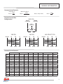
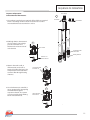
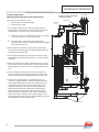
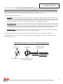
1
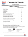
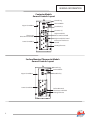
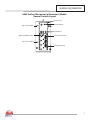
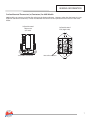
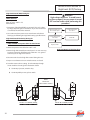
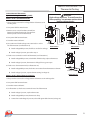
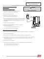
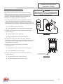
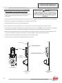
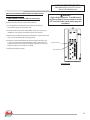
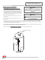
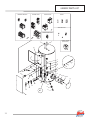
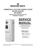
Energy Saver
Commercial Electric Energy Saver
Water Heater
IMMERSION AND SURFACE MOUNTED
THERMOSTAT MODELS
SERVICE
MANUAL
Troubleshooting Guide
and Instructions for Service
(To be performed ONLY by
qualified service providers)
For Models
50(A)*(SF, CF)-**
80(A)*(SF, CF)-**
120(A)*(SF, CF)-**
*Denotes kW Rating
**Denotes Wiring Code
Manual 238-47174-00B - Save this manual for future reference
Commercial Electric
Water Heaters
Table of Contents
Introduction/Tools
General Information
Sequence of Operation
Troubleshooting
Heating Element Testing
Line Voltage Testing
Fuse Testing
High Limit (ECO) Testing (Surface Mounted)
High Limit (ECO) Testing (Surface Mounted @ 600V)
High Limit (ECO) Testing (Contactor Models)
Thermostat Operation Testing (Surface Mounted)
Thermostat Operation Testing (Surface Mounted @ 600V)
Thermostat Operation Testing (Contactor Models)
Contactor Operation Testing
Thermostat Removal & Replacement (Surface Mounted)
Thermostat Removal & Replacement (Contactor Models)
ECO Removal & Replacement (Contactor Models)
ECO Removal & Replacement (Surface Mounted @ 600V)
Heating Element Removal & Replacement
Anode Inspection & Replacement
Generic Parts List
Glossary of Terms
Page
Service Procedure
2
3
10
13
15
16
17
18
19
20
21
22
23
24
26
27
28
29
30
31
32
33
--------I
II
III
IV
V
VI
VII
VIII
IX
X
XI
XII
XIII
XIV
XV
XVI
-----
Introduction
This service manual is designed to aid service and maintenance professionals in the function, proper
diagnosis and repair of Bock Water Heaters Commercial Electric Water Heaters.
The text and illustrations in this manual provide step-by-step instructions to facilitate proper operation and
troubleshooting procedures. Contact Bock Water Heaters Technical Support immediately if diagnosis
cannot be made using the methods described in this service manual.
Tools
- Multi-Meter
- 1-1/2” Deep Well Socket
- 1-1/16” Deep Well Socket
- 1/4” Nut Driver
- Philips Head Screw Driver
- Common Screw Driver
- Thermometer
- Drain Hose.
Other hand tools: pipe wrench, channel locks, pliers (common & needle nose), wire cutters, wire strippers,
allen wrench set, flash light.
2
Commercial Electric
General Information
Bock Waters Heaters Commercial Electric water heaters can be manufacturered
with a choice between two different types of thermostat control options as follows:
Surface Mounted Thermostats.
Immersion Thermostat (contactor models).
The model number is coded to identify the specific thermostat control system used
for a particular unit. Below is a typical model number and coded definitions.
50
SF
6
208/240
Volts
kW Rating
CF - Contactor w/Fuse (Immersion Thermostat)
SF - Surface Thermostat w/Fuse
Tank Capacity
Model Number
Electrical Characteristics
MFG FOR: BOCK WATER HEATERS, INC.
110 S. DICKINSON, MADISON WI 53703
Model No: 50SF-6, 208/240
Serial No: ZB2564812
Cap.
50(gal.)/189.3(liters)
Press: Test 300(psi), Working 150(psi)
Volts
240
Max Temp 180°
Phase Three
Amps 29
kW Each 4
Total kW 12 3 Elements
Wattage rating based upon 60 Hz
Typical Rating Plate
Located on Front of Water Heater
3
GENERAL INFORMATION
Contactor Models
General Controls Layout
Ground Lug
Terminal Block
Upper Control Box
Fuse Block (s)
Contactor (s)
Thermostat
Direct Immersion Bulb
Lower Control Box
High Limit (ECO)
Direct Immersion Bulb
High Limit (ECO) Control
Immersion Thermostat
Control
Heating Elements
Surface Mounted Thermostat Models
General Controls Layout
Ground Lug
Terminal Block
Upper Control Box
Fuse Block (s)
Lower Control Box
Surface Mounted
Thermostats with ECO
Heating Elements
4
GENERAL INFORMATION
600V Surface Thermostat (w/Contactors) Models
General Controls Layout
Ground Lug
Upper Control Box
Terminal Block
Contactor(s)
High Limit (ECO) Control
Surface Thermostats
Lower Control Box
Heating Elements
5
GENERAL INFORMATION
Surface Mounted Thermostats
Surface mounted thermostats are mounted into a bracket above each heating element. The bracket holds the
thermostat against the side of the tank responding to tank surface temperatures to sense a call for heat, set point
temperature and high limit (ECO) activation. As each element has a dedicated thermostat (for all models excluding
600V), it is possible to sequence the elements by varying the settings on the thermostats.
Manual ECO (High Limit)
Reset Button
Surface Mount
Combination Thermostat/
ECO (high limit)
89T Series
Temperature Control Dial
Immersion Style Thermostat Control for
Contactor Models
The thermostat will complete control circuit
voltage upon a call for heat. Likewise, the
control will interrupt control circuit voltage
when the water temperature is sufficient to
satisfy the adjustable temperature limit of
control.
Direct
Immersion
Bulb
Immersion Style High Limit (ECO) Control for
Contactor Models
The high limit (ECO) control will interrupt control
circuit voltage causing the heater to shut down when
the high temperature limit of the control is reached
(196° F ± 4° F). Once the cause for overheated water
has been determined, the control must be manually
reset to restore normal operation.
Manual Reset Button
Direct Immersion Bulb
6
GENERAL INFORMATION
Surface Mounted Thermostats (w/Contactors) for 600V Models
600V models use contactors to deliver line voltage to the heating elements. However, rather than the immersion type
high limit and thermostat devices, surface mounted thermostats are used to operate the control circuit of the water
heater.
Surface Mounted
Thermostat
59T Series
Temperature Control Dial
Surface Mounted
ECO (High Limit)
Manual Reset Button
7
GENERAL INFORMATION
Contactor
Contactor operation is achieved by energizing an operating coil in response to a call for heat from the immersion
thermostat. Upon a call for heat, one or more contactors will energize all heating elements simultaneously. The
operating coils are voltage specific. When contactor replacement is required be sure to order the proper operating coil
based on the voltage rating found on the rating plate located on the front of the water heater.
Terminal Connections of
Contactor Operating Coil
Terminal Connections to the
Fuse Block and/or Terminal Block
Terminal Connections to
the Heating Elements
Direct Immersion “Screw-in” Type Heating Element
Terminal Block
0642
4500W 240V
RC02404524
1- ½“ Hex
Screw-in Flange
Terminal Block Screw
8
Element Rating Ink Stamped
on Side of Terminal Block
Zinc-plated Copper
or Incoloy Sheath
GENERAL INFORMATION
Commonly Used Formulas
(Single Phase)
Watts
Amps =
Volts
(Balanced 3 Phase)
Watts
Amps =
Volts x 1,732
Common Service Wire
Configurations
Watts = Amps x Volts
Ohms =
Volts2
Watts
240V 1Ph
BLACK
Ungrounded
GREEN
Grounding
RED
Ungrounded
240
120
120
208 3Ph
Neutral
A
240 3Ph
B
C
Neutral
A
120
480 3Ph/277 1Ph
B
C
Neutral
B
120
120
208
120
208
277
240
120
208
BLACK
240
RED
C
277
120
RED
A
RED
480
277
240
BLACK
480
RED
RED
480
BLACK
RED
Commonly Used Formulas
208 Volt
240 Volt
277 Volt
380 Volt
415 Volt
480 Volt
600 Volt
kW
1 Phase
3 Phase
1 Phase
3 Phase
1 Phase
3 Phase
3 Phase
1 Phase
3 Phase
3 Phase
6
28.8
16.6
25.0
14.4
21.6
9.1
8.3
12.5
7.2
5.8
9
43.2
25.0
37.2
21.6
32.4
13.6
12.5
18.7
10.8
8.7
12
57.6
33.3
50.0
28.9
43.3
18.2
16.7
25.0
14.4
11.5
13.5
64.9
37.5
56.2
32.5
48.7
20.5
18.8
28.1
16.2
13.0
15
72.1
41.6
62.5
36.1
54.1
22.7
20.9
31.2
18.0
14.4
18
86.5
50.0
75.0
43.4
64.0
27.3
25.0
37.5
21.6
17.3
24
115.4
66.7
100.0
57.8
86.6
36.4
33.4
50.0
28.9
23.1
27
129.8
75.0
112.5
65.0
97.4
41.0
37.5
56.2
32.5
26.0
30
144.2
83.3
125.0
72.2
108.3
45.6
41.7
62.5
36.1
28.9
36
173.0
100.0
150.0
86.7
129.9
54.7
50.1
75.0
43.3
34.6
45
216.3
125.0
187.5
108.3
162.4
68.4
62.6
93.7
54.1
43.3
54
259.6
150.0
225.0
130.0
194.9
82.0
75.1
112.5
65.0
52.0
9
SEQUENCE OF OPERATION
Bock’s commercial electric water heaters can use either immersion thermostats (contactor models) or surface mounted
thermostats. Sequence of operation for each configuration is explained below. It would be impractical to show all wire
diagrams applicable to both configurations. A “typical wiring diagram” is illustrated to aid in understanding the principles of
the operating sequence.
Immersion Thermostats (Contactor Models): Configured to use a single immersion thermostat to control one or more
contactors to energize or de-energize all elements simultaneously. In addition, a separate high limit (ECO) control with manual
reset is wired in series with the thermostat. Both controls use a direct immersion bulb inserted into the tank to sense water
temperature. Immersion thermostat and high limit control are mounted to provide temperature adjustment and manual reset
access from the exterior of the unit.
Surface Mounted Thermostats: Surface mounted thermostats are mounted inside the lower control box, in a bracket above
each heating element. The bracket holds the thermostat against the side of the tank, responding to tank surface temperatures
to sense a call for heat, set-point temperature and high limit (ECO) activation. As each element is controlled by a dedicated
thermostat, it is possible to sequence the elements by varying the settings on the thermostat. However, 600V models with
Line Voltage
surface mounted thermostats operate contactors in the
same manner as an immersion thermostat model, only using
surface thermostats to sense the call for heat.
Sequence of operation for each system is explained below.
OR
Fuse Block
Terminal Block
Sequence of Operation:
Immersion Thermostat (Contactor Models).
The system has two distinct circuits:
1. Power Circuit (solid line).
2. Control Circuit (dotted line).
Contactor
Coil
ECO
(High Limit)
Contactor
1. Line voltage is applied across terminals of fuse block or a
terminal block. Line voltage continues down and connects
to terminals L1, L2 and L3 of one or more contactors.
A. Contactor is open (no call for heat), so there is no
voltage across terminals T1, T2 and T3 of contactor.
B.
T’stat
The contactor is controlled by the control circuit
consisting of the immersion thermostat, ECO (high
limit) and contactor coil.
2. When the thermostat calls for heat, contacts close inside
the thermostat completing the circuit through the ECO and
energizing the contactor coil.
3. The energized contactor coil causes the contactor to close
energizing the elements from terminals T1, T2 and T3 of the
contactor.
4. When the temperature setting of the thermostat is reached,
the contacts in the thermostat open. This interrupts current
flow through the control circuit de-energizing the contactor
coil.
5. The de-energized contactor coil causes the contactor to
open, interrupting current flow through the elements. The
heater is now in stand-by, waiting for the next call for heat.
10
Heating Elements
SEQUENCE OF OPERATION
Sequence of Operation:
Surface Mounted Thermostats.
Line Voltage
1
1. Line voltage is applied across terminals of fuse block or a terminal
block. Line voltage continues down and connects to surface
mounted thermostats at terminals L1 and L3.
2. ECO (high limit) in thermostat is
closed, so there is line voltage
present at terminal L4 of
thermostats and to one side of
each element.
Fuse Block
Terminal Bloc
2
ECO Closed
Surface Mounted
Thermostat
Heating Element
Power to one
side of element
3. Water in the tank is cold, so
all thermostats are closed at
terminal T2 (calling for heat). This
completes the circuit and allows
current to flow through heating
elements.
4. As each thermostat is satisfied, it
opens at terminal T2, interrupting
current flow through the
respective element. The system
is now in stand-by mode waiting
for the next call for heat.
Thermostat closed
at terminal T2
3
4
Thermostat open
at terminal T2
11
SEQUENCE OF OPERATION
Sequence of Operation:
600V Surface Mounted Thermostats (w/Contactors).
The system has two distinct circuits.
1. Power Circuit - Line Voltage (600V)
2. Control Circuit - 120V
6 Element Configuration Shown
(9 Elements Possible)
Line Voltage
Fuse Block
Transformer
60VA
1. Line voltage is applied across terminals of fuse block or a
terminal block. Line voltage continues down and connects
to terminals L1, L2 and L3 of one or more contactors.
A) Contactor is open (no call for heat), so there is no voltage
across terminals T1, T2, and T3 of contactor.
B) The contactor is controlled by the control circuit
consisting of the surface mounted thermostat, ECO (high
limit) and contactor coil.
Contactor
2. When the thermostat calls for heat, contacts close inside
the thermostat completing the circuit through the ECO and
energizing the contactor coil.
3. The energized contactor coil causes the contactor to close,
energizing the elements from terminals T1, T2 and T3 of the
contactor.
4. When the temperature setting of the thermostat is reached,
the contacts in the thermostat open. This interrupts current
flow through the control circuit de-energizing the contactor
coil.
High Limit
5. The de-energized contactor coil causes the contactor to
open, interrupting current flow through the elements. The
heater is now in stand-by waiting for the next call for heat.
6. Notice in the wiring diagram at right that each row of
elements is equipped with a surface mounted thermostat
on the highest element in the row. These thermostats are
individually wired in series to the contactor whose line
voltage corresponds to the same row of elements. Each
thermostat and contactor combination are wired to the
ECO in parallel. This allows for each row of elements to
be powered “ON” independent of the other element rows.
However, the ECO is wired in series so that voltage can be
interrupted to the entire control circuit if the ECO senses that
the tank water has become overheated.
59T
59T
Heating Elements
12
TROUBLESHOOTING
The most common cause of improper electric water heater operation can be linked to heating element failure.
When troubleshooting an electric water heater with the incidence of “no hot water” or “insufficient amount of hot water” it is
always a good idea to check the heating elements first following the procedure on Page 15.
Common heating element failures are:
1. Dry Firing. Elements may be partially submerged in water or most likely, completely exposed with no water in the tank
at all. In open air, an energized element (dry-fired) will become completely inoperable within seconds. In some cases
sediment or lime build up around an element can eventually cause an air pocket, resulting in a dry-fired element. When
element replacement is required, be sure tank is full of water prior to energizing the water heater.
2. Grounded Element. In most cases, an element with a short circuit to ground will cause the circuit breaker in the service
panel to open or shut off. In some cases there may not be enough current draw for the circuit breaker to open. This will
allow the heating element to be in continuous operation resulting in overheated water, limited only by the ECO located
in the thermostat circuit. Repeated actuation of the ECO usually is the result of a grounded heating element.
3. Sediment Buildup. Slow hot water recovery can usually be traced back to sediment or lime build-up around heating
element. Sediment build-up can also, over time, cause a dry-fired element.
If a heating element is found to be inoperative, it must be replaced. Follow service procedure MCE-XV on Page 30.
The illustration below shows a common “screw-in” type heating element identifying certain features commonly referred to
throughout this manual.
Typical Direct Immersion “Screw-In” Type Heating Element
Terminal Block
Zinc-plated Copper
or Incoloy Sheath
0642
4500W 240V
RC02404524
1- ½“ Hex
Screw-in Flange
Terminal Block Screw Element Rating Ink Stamped
on Side of Terminal Block
13
TROUBLESHOOTING
Quick Step Plan to Hot Water
1. STOP, DANGER! Turn power “OFF” to water heater.
2. Check all wire connections to insure that they are snug and
corrosion free.
WARNING
High voltage exposure. Use caution when
making voltage checks to avoid hazard to
life or property.
3. Reset high limit (ECO) (Page 18-20).
4. Check for inoperative heating element (Page 15).
5. Check line voltage (Page 16), and internal fuses (Page 17).
6. Refer to table below if items 1 through 5 above do not correct problem.
SYMPTOM
CORRECTIVE ACTION
SERVICE
PROCEDURE
No Hot Water
1. No power to heater.
2. Blown water heater fuses.
3. Loose wire connections.
4. Inoperative heating elements.
5. Inoperative thermostat(s)
6. Open ECO.
7. Inoperative contactor(s).
1. Check circuit breakers at service panel.
2. Check water heater fuses.
3. Check all wire connections.
4. Check heating element(s).
5. Check thermostat(s) operation.
6. Reset (check) ECO.
7. Check contactor operation.
2. III, Page 17
4. I, Page 15
5. VII-IX, Page 21-23
6. IV, VI, Page 18-20
7. X, Page 24-25
Not Enough
Hot Water or
Continues
Operation
1. Inoperative heating element.
2. Sediment or lime buildup on element(s).
3. Thermostat(s) set too low.
4. Inoperative thermostat(s).
5. Inoperative contactor(s).
6. Loose wire connection.
7. High demand period.
8. Undersized heater.
9. Very cold inlet water to heater.
10. Plumbing connections reversed.
1. Check heating element(s).
2. Clean or replace heating element(s).
3. Increase thermostat setting.
4. Check thermostat(s).
5. Check contactor operation.
6. Check all wire connection.
7. Reduce demand.
8. Replace with larger heater.
9. Temper water to heater.
10. Correct plumbing connections.
1. I, Page 15
2. XV, Page 30
4.VII-IX, Page 21-23
5. X, Page 24-25
Slow Hot Water
Recovery
1. Sediment or lime buildup on element(s).
2. Loose wire connections.
3. Inoperative thermostat(s).
4. Inoperative contactor(s).
5. Derated heating element installed.
1. Clean or replace heating elements.
2. Check all wire connections.
3. Check thermostat(s).
4. Check contactor operation.
5. Verify element voltage and wattage rating.
1. XV, Page 30
3. VII-IX, Page 21-23
4. X, Page 24-25
5. See Page 8
Overheated
Water
1. Surface thermostat(s) not flush with tank.
2. Grounded heating element(s).
3. Thermostat set too high.
4. Inoperative thermostat(s).
5. Inoperative ECO.
1. Check surface thermostat(s) mounting.
2. Check heating element(s).
3. Adjust thermostat(s) to desired setting.
4. Check thermostat(s).
5. Check ECO.
1. XI, Page 26
2. I Page 15
4. VII-IX, Page 21-23
5. IV-VI, Page 18-20
1. Lime formation on element(s).
2. High or low line voltage.
1. Clean or replace heating element(s).
2. Verify line voltage to heater.
1. XV, Page 30
2. II, Page 16
1. Low line voltage.
2. Debris between contactor plates.
3. Incorrect or defective operating coil.
4. Loose wire connections.
1. Verify line voltage to heater.
2. Replace contactor.
3. Replace contactor.
4. Check wire connections.
1. II, Page 16
Noisy (singing or
hissing) Elements
Noisy Contactor
14
PROBABLE CAUSE
SERVICE PROCEDURE I
Heating Element Testing
Test for Open or Burned Out Element.
1. STOP, DANGER! Turn power “OFF” to water heater.
2. Remove access cover from lower control box. Remove
insulation from inside of control box.
WARNING
High voltage exposure. To avoid hazard
to life or property, be sure power is turned
OFF to water heater while performing this
procedure.
3. Disconnect wires from heating element.
4. Set multi-meter to “ohms” setting.
5. Touch probes of multi-meter to screw terminals of heating
element (see illustration 1).
6. Reading should be 12.8 ohms (± 6%) for a 240 volt, 4500 watt
element, see table below for other elements.
NOTE
Disconnect
Element
Wires
Ohms = Volts2
Watts
A reading outside the range using the formula
above (± 6%) indicates a bad element and the
element must be replaced.
Ohms of Electrical Resistance
for Commonly Used Elements
Element Screw Terminals
Voltage Rating of Element
Element
Wattage
2000
3000
4000
4500
5000
6000
208
21.6
14.4
10.8
9.6
8.7
7.2
240
28.8
19.2
14.4
12.8
11.5
9.6
Illustration 1
480
115.2
76.8
57.6
51.2
46.1
38.4
Test for Grounded Heating Element
(Damaged Heating Element with Short Circuit to Ground).
1. STOP, DANGER! Turn power “OFF” to water heater.
2. Remove access cover from lower control box. Remove
insulation from inside of control box.
3. Disconnect wires from heating element.
NOTE
Disconnect
Element
Wires
4. Set multi-meter to “ohms” setting.
5. Touch one probe of multi-meter to either screw terminal
of heating element and the other on the element flange
(see illustration 2). There should be no reading on the ohm
meter. Any reading indicates a grounded element and the
element must be replaced. Repeat this step for the other
screw terminal.
Element Flange
Element
Screw Terminal
Illustration 2
15
SERVICE PROCEDURE II
Line Voltage Testing
Line Voltage Testing.
Line voltage (single phase or three phase) will connect to a
terminal block or directly to a fuse block located inside the
control panel.
Determine heaters voltage and phase by referring to the
rating plate located on the front of the water heater. Apply the
appropriate phase procedure below to determine if proper line
voltage is present.
Single Phase Line Voltage Testing.
1.
WARNING
High voltage exposure. To avoid hazard to
life or property, use extreme caution when
making voltage checks.
Line voltage from
service panel
connected to Terminal block
of heater
OR
Line voltage from
service panel
connected to Fuse block
of heater
STOP, DANGER! Turn power “OFF” to water heater.
2. Open upper control panel door.
3. Determine connection point for line voltage from service
panel, terminal block or fuse block.
4. Set multi-meter to volts AC. Be sure to scale meter for
appropriate voltage.
5. Use caution and turn power “ON” to water heater.
6. Use caution and check voltage across top terminals where
service voltage connects to water heater (see illustration 3).
A) Rated voltage IS present, power to the water heater is
okay.
Check voltage across
top terminals.
Illustration 3
B) Rated voltage NOT present, check service panel.
Three Phase Line Voltage Testing.
1. STOP, DANGER! Turn power “OFF” to water heater.
Line voltage from
service panel
connected to Terminal block
of heater
OR
2. Open upper control panel door.
3. Determine connection point for line voltage from service
panel, terminal block or fuse block.
4. Set multi-meter to volts AC. Be sure to scale meter for
appropriate voltage.
5. Use caution and turn power “ON” to water heater.
6. Use caution and check voltage across top terminals where
service voltage connects to water heater (see illustration 4).
A) Rated voltage IS present, power to the water heater is
okay.
B) Rated voltage NOT present, check service panel.
16
Check voltage across
top terminals.
Illustration 4
Line voltage from
service panel
connected to Fuse block
of heater
SERVICE PROCEDURE III
Fuse Testing
Fuse Testing.
1. STOP, DANGER! Turn power “OFF” to water heater.
2. Open upper control box to allow access to fuse block.
3. Locate fuse block and remove fuses.
WARNING
High voltage exposure. To avoid hazard
to life or property, be sure power is turned
OFF to water heater while performing this
procedure.
4. Set multi-meter to the ohms setting.
5. Check continuity across fuse (see illustration 5).
A) Continuity IS present, fuse is okay.
B) Continuity NOT present, replace fuse.
Illustration 5
17
SERVICE PROCEDURE IV
High Limit (ECO) Testing
High Limit Control (ECO) Testing for
Surface Thermostat Models (NOT including 600V)
1. This procedure assumes line voltage and fuses are in working
order.
WARNING
High voltage exposure. To avoid hazard to
life or property, use extreme caution when
making voltage checks.
2. This procedure illustrates testing of just one surface thermostat. Repeat this
procedure for all surface thermostats on the water heater.
ECO reset
button
3. Turn power “OFF” to water heater.
4. Remove lower control box cover and remove insulation from inside of control box.
5. Remove plastic cover from thermostat(s).
6. Turn power “ON” to water heater.
7. Use caution and check voltage across terminals L1 and L4 for all thermostats (see
illustration 6).
A) Rated voltage IS present, ECO is okay.
B) Rated voltage NOT present, proceed to step 8.
ELEMENT
Illustration 6
8. Turn power “OFF” to water heater and firmly press ECO reset button on thermostat(s).
Turn power “ON” to water heater and recheck voltage across terminals L1 and L4 of thermostat(s).
A) Rated voltage IS present, the ECO has previously opened indicating the water in the tank, at some point, did overheat.
Check the following:
1.
2.
3.
Thermostat must be in full contact with tank.
Be sure heating element(s) is not shorted to ground (see Page 15).
Proper thermostat operation (see Page 21).
B) Rated voltage NOT present, water in tank may be overheated.
1.
2.
18
If water is overheated, turn “OFF” power to water heater and flow water through tank to cool below set point of
upper thermostat. Reset ECO and recheck voltage.
If water is cool, replace thermostat(s).
SERVICE PROCEDURE V
High Limit (ECO) Testing
High Limit Control (ECO) Testing for
600V Surface Thermostat Models.
1. This procedure assumes line voltage, transformer, fuses and
thermostat are in working order.
WARNING
High voltage exposure. To avoid hazard to
life or property, use extreme caution when
making voltage checks.
2. Turn power “OFF” to water heater.
3. Remove lower control box cover and remove insulation from inside of control box.
ECO reset
button
4. Use caution and check continuity across terminals 1 and 2 (see illustration 7).
A) Continuity IS present, ECO is okay.
B) Continuity NOT present, proceed to step 5.
5. Turn power “OFF” to water heater and firmly press ECO reset button on
thermostat(s). Turn power “ON” to water heater and recheck continuity across
terminals 1 and 2 of thermostat(s).
A) Continuity IS present, the ECO has previously opened indicating the water in
the tank, at some point, did overheat. Check the following:
1.
2.
3.
Illustration 7
Thermostat must be in full contact with tank.
Be sure heating element(s) is not shorted to ground (see Page 15).
Proper thermostat operation (see Page 22).
B) Continuity NOT present, water in tank may be overheated.
1.
2.
If water is overheated, turn “OFF” power to water heater and flow water through tank to cool below set point of
upper thermostat. Reset ECO and recheck continuity.
If water is cool, replace ECO.
19
SERVICE PROCEDURE VI
High Limit (ECO) Testing
High Limit Control (ECO) Testing for
Contactor Models
WARNING
High voltage exposure. To avoid hazard
to life or property, be sure power is turned
OFF to water heater while performing this
procedure.
Switch Contacts:
Normally closed.
Open on rise @ 196°F ± 4°F.
Manual Reset.
1. Determine of high limit (ECO) has actuated. This can be done
by simply depressing the reset buttons. If you hear and/or feel
a small click, the switch has actuated.
2. Use caution and turn power on to water heater and observe
heating cycle following the high limit heating cycle flow chart.
High Limit Control Continuity Testing for
Contactor Models
Observe heating cycle.
Does switch open?
N
Is water temperature
over 196°F?
Y
Y
Is water temperature
over 196°F?
Y
Switch OK.
N
1. STOP, DANGER! Turn power “OFF” to water heater.
Replace switch.
2. Water temperature must be below 196°F ± 4°F.
3. Remove high limit switch from control panel. It is not necessary
to remove immersion bulb from tank at this time. See general
controls layout on Page 4 for location.
High Limit Heating Cycle Flow Chart
4. Disconnect wire leads to high limit control during this test.
5. Depress reset buttons to insure switch contacts are closed.
6. Set multi-meter to ohms setting. Check continuity through
circuit A and B as showing in the illustrations below.
A) Continuity IS present, switch is okay.
B) Continuity NOT present, replace switch.
NOTE
Disconnect
Wire Leads to Control
Circuit “A” Continuity Testing
20
Circuit “B” Continuity Testing
SERVICE PROCEDURE VII
Thermostat Testing
Surface Mounted Thermostat.
Operation Testing (NOT including 600V).
WARNING
High voltage exposure. To avoid hazard to
life or property, use extreme caution when
making voltage checks.
Water in Tank is Cold with Power ON.
1. This procedure assumes line voltage, ECO and elements are in
working order.
2. Turn power “OFF” to water heater.
3. Remove access cover from lower control box.
Remove insulation from inside of control box.
Remove plastic cover from thermostat.
4. Turn power “ON” to water heater.
5. Set multi-meter to Volts AC.
6. Use caution and check voltage across terminals L1 and L3
for all thermostats (see illustration 8).
ELEMENT
Illustration 8
ELEMENT
Illustration 9
A) Rated voltage NOT present, check fuses and/or line voltage.
B) Rated voltage IS present, proceed to step 7.
7. Check across terminals L4 and T2 of thermostat (see illustration 9).
A) Rated voltage NOT present, recheck ECO. If ECO is okay, replace thermostat.
B) Rated voltage IS present, thermostat is calling for heat, go to step 8.
8. Check across element terminals (see illustration 10)
A) Rated voltage NOT present, check wire connections from thermostat to element.
ELEMENT
B) Rated voltage IS present, repeat element testing (see Page 15).
Water in Tank is Above Thermostat Settings.
Illustration 10
1. This procedure assumes line voltage, ECO and elements are in working order.
2. Turn power “ON” to water heater.
3. Set multi-meter to Volts AC.
4. See illustration 9, check across terminals L4 and T2 of thermostat.
A) Rated voltage IS present, replace thermostat.
B) Rated voltage NOT present, thermostat is okay.
C) Lower than rated voltage IS present, recheck for grounded element (see Page 15).
21
SERVICE PROCEDURE VIII
Thermostat Testing
600V Surface Mounted Thermostat Models
Operation Testing.
Water in Tank is Cold with Power ON.
WARNING
High voltage exposure. To avoid hazard to
life or property, use extreme caution when
making voltage checks.
1. This procedure assumes line voltage, ECO, transformer,
thermostat, and elements are in working order.
2. Turn power “OFF” to water heater.
3. Remove access cover from lower control box.
Remove insulation from inside of control box.
4. Using a phillips head screwdriver, disconnect the wire lead at terminal 2
of the thermostat. Only check one thermostat at a time to insure wires
are correctly reinstalled upon completion. Mark wires if necessary for
reinstallation.
5. Set multi-meter to check continuity.
6. Use caution and check continuity across terminals 1 and 2 for all
thermostats (see illustration 11).
A) Continuity NOT present, replace thermostat.
Illustration 11
B) Continuity IS present, thermostat is okay.
Water in Tank is Above Thermostat Settings.
1. This procedure assumes line voltage, ECO, thermostat, transformer, and elements are in working order.
2. Turn power “OFF” to water heater.
3. Remove access cover from lower control box. Remove insulation from inside of control box.
4. Using a phillips head screwdriver, disconnect the wire lead at terminal 2 of the thermostat. Only check
one thermostat at a time to insure wires are correctly reinstalled upon completion. Mark wires if
necessary for reinstallation.
5. Set multi-meter to check continuity.
6. Use caution and check continuity across terminals 1 and 2 for all thermostats (see illustration 11).
A) Continuity NOT present, replace thermostat.
B) Continuity IS present, thermostat is okay.
22
SERVICE PROCEDURE IX
Thermostat Testing
Immersion Thermostat Operation Testing.
Thermostat Specification.
Calibration: 184°F/176°F
Max Differential: 6°F
Operating Range: 80°F to 180°F
WARNING
High voltage exposure. To avoid hazard to
life or property, use extreme caution when
making voltage checks.
Providing the water temperature in tank is within the operating range of the
thermostat, checking thermostat operation can be as simple as rotating the
thermostat dial and listening to the contactor(s) to see if they respond to a call
for heat.
Use caution and turn power “ON” and rotate the thermostat dial to call for heat.
With water temperature below the thermostat setting, the contactor(s) close.
With the contacts closed, use caution and check for rated voltage across lower
terminals of contactor(s) (see illustration 12). If rated voltage is present, the
thermostat is calling for heat.
Rotate thermostat dial to the minimum setting. With water temperature above
the thermostat setting the contactor(s) will open. With the contacts open,
voltage should not be present at lower terminals of contactor(s).
L1
L2
L3
T1
T2
T3
Check voltage across
lower terminals of contactor(s)
Illustration 12
Thermostat Control Continuity Testing.
1. This procedure assumes line voltage, ECO and contactor(s) are in working order.
2. Turn power “OFF” to water heater.
3. Remove access cover from lower control box. Remove insulation from inside of control box.
4. Locate thermostat control (see general controls layout on Page 4) and remove wire leads to
control screw terminals.
5. Water temperature in tank must be within operating range of thermostat for this test. If above or below,
it will be necessary to drain tank and remove thermostat immersion bulb from tank to warm or cool the
Thermostat Immersion Bulb
bulb to be within operating range of thermostat.
6. Set multi-meter to the “Ohms” setting.
7. Rotate thermostat dial to highest setting.
8. Check across screw terminals of control
(see illustration 13).
Thermostat
Dial
A) Continuity NOT present, replace thermostat.
B) Continuity IS present, proceed to step 9.
9. Rotate thermostat dial to lowest setting.
10. Check across screw terminals of control
(see illustration 13).
A) Continuity NOT present, thermostat is okay.
B) Continuity IS present, replace thermostat.
NOTE: Disconnect
Wire Leads to Control
Screw Terminals
Illustration 13
23
SERVICE PROCEDURE X
Contactor Testing
Contactor Operation Testing.
WARNING
High voltage exposure. To avoid hazard to
life or property, use extreme caution when
making voltage checks.
Noisy Contactor.
Noisy or chattering contactor operation in most cases is due to voltage variations being supplied to the water heater.
Extended periods of voltage variations will cause damage to the operating coil of the contactor causing noisy operation.
Determine that service voltage to the unit meets the electrical requirements per the rating plate located on the front of the
water heater.
In addition, debris between the contact plates will cause noisy operation.
Contactor Operating Coils.
Contactor operation is achieved by energizing an operating coil in response to a call for heat from the thermostat. There are
three different operating coils used depending on voltage rating of the water heater as follows:
Description
Color Code
208/240 Volt Coil
277 Volt Coil
480 Volt Coil
Green
Blue
Black
All the coils have a color code for visual confirmation. In addition, the 277 and 480 volt coils are labeled with voltage rating for
proper identification. All contactors supplied for replacement are equipped with the 208/240 volt operating coil. By removing
the rear mounting plate of the contactor, the operating coils can be changed based on desired service voltage. When
contactor replacement is required be sure to order the proper operating coil base on the voltage rating found on the rating
plate located on the front of the water heater.
Rear Mounting Plate
Operating Coil
Color Code Location
Identification Label Location
24
SERVICE PROCEDURE X
Contactor Testing
Contactor Operation Testing (continued).
This procedure assumes control circuit is operating correctly.
Providing the water temperature in tank is within the operating
range of the thermostat, checking contactor operating can be
as simple as rotating the thermostat dial and listening to the
contactor(s) to see if they respond to a call for heat.
WARNING
High voltage exposure. To avoid hazard to
life or property, use extreme caution when
making voltage checks.
1. Turn power “ON” and rotate thermostat dial to the maximum
setting. With water temperature in tank below the thermostat
setting the contactor(s) will close. With the contacts closed, check
for line voltage across operating coil terminals (see illustration 14).
A) Line voltage IS present, go to step 2.
B) Line voltage NOT present, verify control circuit operation.
2. Check for rated voltage across lower terminals of contactor(s)
(see illustration 15).
A) Rated voltage IS present, go to step 3.
Illustration 14
B) Rated voltage NOT present, replace contactor.
3. Rotate thermostat dial to the minimum setting. With water
temperature in tank above thermostat setting, the contactor(s) will
open. With the contacts open, voltage should not be present at
lower terminals of contactor(s).
4. Check for line voltage across operating coil terminals
(see illustration 14).
L1
L2
L3
T1
T2
T3
A) Line voltage IS present, verify control circuit operation.
B) Line voltage NOT present, go to step 5.
5. Check for rated voltage across lower terminals of contactor(s)
(see illustration 15).
A) Rated voltage IS present, replace contactor.
Check voltage across
lower terminals of contactor(s)
Illustration 15
B) Rated voltage NOT present, contactor is okay.
25
SERVICE PROCEDURE XI
Thermostat Removal and Replacement
Surface Mounted Thermostat Removal and Replacement
WARNING
High voltage exposure. To avoid hazard
to life or property, be sure power is turned
OFF to water heater while performing this
procedure.
1. STOP, DANGER! Turn power “OFF” to water heater.
2. Remove access cover from lower control. Remove insulation
from inside of control box. Remove plastic cover from
thermostat.
3. Disconnect wires from thermostat terminals. It may be necessary to label wires for proper reconnection to new thermostat.
4. Note thermostat temperature setting for proper setting of new thermostat.
5. Slide thermostat upwards and out of mounting bracket.
6. Use a stiff brush to remove any debris or loose scale from tank surface where new thermostat will be installed.
7. Slide new thermostat down into thermostat bracket until it snaps into place. IMPORTANT - thermostat must set completely
flat or flush to tank surface. An improperly installed thermostat will cause improper water heater operation.
8. Refer to the wire diagram located on the inside of the upper control box cover and reconnect wires to the thermostat. Be
sure wire connections are snug and corrosion free. Do not over tighten as that may damage thermostat.
9. Set thermostat to the original thermostat setting found on the old thermostat.
10. Restore power to water heater and verify proper heater operation.
Tank Surface
Proper Thermostat mounting
flush with tank surface
Thermostat
Improper Thermostat mounting.
Thermostat not flush with tank surface
Thermostat
mounting
bracket
Front View
Thermostat Mounting
Side View
Proper Thermostat
Mounting
26
Side View
Improper Thermostat
Mounting
SERVICE PROCEDURE XII
Thermostat Removal and Replacement
Immersion Thermostat Removal and Replacement
WARNING
High voltage exposure. To avoid hazard
to life or property, be sure power is turned
OFF to water heater while performing this
procedure.
1. STOP, DANGER! Turn power “OFF” to water heater.
2.Turn off cold water supply to heater. Connect hose to drain
spigot of water heater and route to an open drain. Open a
nearby hot water faucet to vent heater for draining. Open
drain spigot of water heater and allow water heater to
drain to a point below the immersion bulb location (see
illustration 16).
3. Close drain spigot and remove hose.
4. Remove lower control box cover and insulation.
5. Locate thermostat inside lower control box mounted
to the right side of the box below the ECO control
(see illustration 16).
6. Follow copper capillary tube from thermostat to the
immersion bulb location and remove immersion bulb
from tank using 11/16” wrench.
Immersion
Thermostat Bulb
Location
7. Remove (pull) thermostat control dial from stem of
thermostat.
8. Remove the two thermostat mounting screws located
under thermostat dial (see illustration 16).
9. Once thermostat is removed, disconnect wire leads to the
thermostat. NOTE: It may be necessary to identify wires
for proper reconnection to new thermostat.
ECO
Control
Thermostat Control
Mounting Screws
Located Under
Thermostat Dial
Copper Capillary
Tube
Immersion
Thermostat
Control
10. Refer to wiring diagram located on the inside of the
upper control box cover and properly reconnect wire
leads to new thermostat and remount control inside
control box using screws from step 8.
Illustration 16
11. Replace control dial to stem of thermostat.
12. Loosen ferrule nut of immersion bulb (see illustration 17).
Immersion
Bulb
Ferrule
Nut
Tank
Nut
Copper
Capillary
Tube
Illustration 17
13. Position tank nut at end of immersion bulb as shown in illustration 17. Insert immersion bulb into tank and tighten tank
nut.
14. Gently pull copper capillary tube to insure the immersion bulb is in a horizontal position as shown in illustration 17 and
tighten ferrule nut.
15. Resume water supply, full tank and check for leaks.
16. Be sure tank is full of water and resume power supply to water heater. Verify proper thermostat operation.
27
SERVICE PROCEDURE XIII
Contactor Model High Limit (ECO) Control
Removal and Replacement
Contactor Model High Limit (ECO) Control
Removal and Replacement.
WARNING
High voltage exposure. To avoid hazard
to life or property, be sure power is turned
OFF to water heater while performing this
procedure.
1. STOP, DANGER! Turn power “OFF” to water heater.
2.Turn off cold water supply to heater. Connect hose to drain
spigot of water heater and route to an open drain. Open a
nearby hot water faucet to vent heater for draining. Open
drain spigot of water heater and allow water heater to drain to a
point below the immersion bulb location (see illustration 18).
3. Close drain spigot and remove hose.
4. Remove lower control box cover and insulation.
5. Locate ECO Control inside lower control box mounted
to the right side of the box above the thermostat control
(see illustration 18).
6. Follow copper capillary tube from ECO Control to the immersion
bulb location and remove immersion bulb from tank using
11/16” wrench.
ECO
Immersion Bulb
Location
ECO
Control
7. Remove the two ECO control mounting screws located outside
the lower control box.
8. Once ECO control is removed, disconnect wire leads to the
control. NOTE: It may be necessary to identify wires for proper
reconnection to new control.
Copper Capillary
Tube
Thermostat
Control
9. Refer to wiring diagram located on the inside of the upper
control box cover and properly reconnect wire leads to new ECO
control and remount control inside control box using screws
from step 7.
10. Loosen ferrule nut of immersion bulb. (see illustration 19).
Immersion
Bulb
Ferrule
Nut
Illustration 18
Copper
Capillary
Tube
Tank
Nut
Illustration 19
11. Position tank nut at end of immersion bulb as shown in illustration 19. Insert immersion bulb into tank and tighten tank
nut.
12. Gently pull copper capillary tube to insure the immersion bulb is in a horizontal position as shown in illustration 19 and
tighten ferrule nut.
13. Resume water supply, full tank and check for leaks.
14. Be sure tank is full of water and resume power supply to water heater. Verify proper ECO operation.
28
SERVICE PROCEDURE XIV
600V Model High Limit (ECO) Control
Removal and Replacement
600V Surface Thermostat Model High Limit (ECO) Control
Removal and Replacement.
1. STOP, DANGER! Turn power “OFF” to water heater.
2. Remove lower control box cover and insulation.
WARNING
High voltage exposure. To avoid hazard
to life or property, be sure power is turned
OFF to water heater while performing this
procedure.
3. Locate high limit switch (ECO) mounted to the tank above
the element spuds (see illustration 20).
4. Disconnect wire leads to the ECO. NOTE: It may be necessary to
identify wires for proper reconnection to the new control.
5. Remove the two ECO mounting nuts holding the sensor to the tank.
Take care not to damage the mounting studs.
6. Fasten the replacement ECO to the tank using the nuts from step
5. Take care not to damage the mounting studs. Refer to wiring
diagram located on the inside of the upper control box cover and
properly reconnect wire leads to new ECO.
7. Verify proper ECO operation.
High Limit Switch
Mounting Stud
Illustration 20
29
SERVICE PROCEDURE XV
Heating Element Removal
and Replacement
Heating Element Removal and Replacement.
WARNING
High voltage exposure. To avoid hazard
to life or property, be sure power is turned
OFF to water heater while performing this
procedure.
1. STOP, DANGER! Turn power “OFF” to water heater.
2. Turn off cold water supply to heater. Connect hose to drain
spigot of water heater and route to an open drain. Open a
nearby hot water faucet to vent heater for draining. Open
drain spigot of water heater and allow heater to drain to a
point below the element(s).
3. Close drain spigot and remove hose.
4. Remove access cover and insulation from lower control
box. Remove plastic cover from thermostat.
5. Disconnect wires from element terminals.
6. Remove element from tank using 1-½” deep well socket or
appropriate wrench. Unscrew element counter-clockwise
to remove from tank.
WARNING
Heater components and stored water may be
HOT when performing the following steps in
this procedure. Take necessary precaution to
prevent personal injury.
7. Be sure to remove old element gasket from the tank. It is recommended to replace the gasket with a new one.
8. Check new element terminal block for proper electrical rating. NOTE: Some elements have dual ratings, be sure to check all
surfaces of the element terminal block (see illustration 21).
9. Apply new element gasket to the new element. Be sure gasket is seated flat against element flange without rolls or gaps
(see illustration 21).
10. Clean any debris from element fitting on tank.
11. Thread new element clockwise into tank. Tighten element using 1-½” deep well socket or appropriate wrench. Do not over
tighten, over tightening may damage element gasket.
12. Reconnect wires to element. Be sure connections are snug and corrosion free. Do not over right as that may damage
terminal block.
13. Resume water supply to heater. Be sure tank is full of water and check for leaks.
14. Reinstall plastic thermostat protector(s).
15. Reinstall insulation and control box cover.
16. To resume operation BE SURE TANK IS FULL OF WATER and restore power to water heater. Verify proper heater operation.
Element Rating.
Example: (4500 Watt, 240 Volt)
Date Code
Element Flange
0642
4500W 240V
RC02404524
Element Gasket Seated Flat Against
Element Flange Without Rolls or Gaps
Terminal
Block
Manufacturer Identification
Illustration 21
30
SERVICE PROCEDURE XVI
Anode Rod Inspection and Replacement
Anode Rod Inspection and Replacement.
1. STOP, DANGER! Turn power “OFF” to water heater.
2. Turn off cold water supply to heater. Connect hose to drain
spigot of water heater and route to an open drain. Open a
nearby hot water faucet to vent heater for draining. Open
drain spigot of water heater and allow heater to drain to a
point below the anode rod locations at the top of the tank.
3. Close drain spigot and remove hose.
4. Remove the plastic anode rod access plugs at the anode
rod locations.
5. Remove anode rods from the water heater using a 1-1/16”
socket wrench.
WARNING
High voltage exposure. To avoid hazard
to life or property, be sure power is turned
OFF to water heater while performing this
procedure.
WARNING
Heater components and stored water may be
HOT when performing the following steps in
this procedure. Take necessary precaution to
prevent personal injury.
6. Visually inspect anode rods. Anode rods should show signs of depletion, this is normal. If depletion is 1/2 of the original
anode rod diameter (original diameter is approximately ¾”), replacement is recommended. If any of the steel core of the
anode rod is exposed, replacement is recommended.
7. Upon completion of inspection and/or subsequent replacement of the anode rod, reinstall the anode into the water heater,
resume water supply, refill water heater with water and check for leaks.
8. To resume operation, BE SURE TANK IS FULL OF WATER and turn power “ON” to water heater.
Anode Rod Locations
31
GENERIC PARTS LIST
TERMINAL BLOCKS
31
FUSE BLOCKS
CONTACTORS
FUSES
32
43
39
44
45
36
GROUND LUGS
37
33
40
41
CONTACTOR COILS
46
34
35
35
38
48
42
1
47
TRANSFORMER
(600V ONLY)
2
30
50
3
3A
8
4
4A
6
29
28
7
5
49
9
27
10
5A
26
20
19
21
17
16
15
22
23
14
18
32
11/11A
12/12A
13
25
24
10A
GENERIC PARTS LIST
Item
1
2
3
3A
4
5
5A
6
7
8
9
10
10A
11
11A
12
12A
13
14
15
16
17
18
19
20
21
22
23
Description
Anode Rod
Hot Water Outlet Nipple
T&P Nipple
T&P Coupling
T&P Relief Valve
High Limit Switch
Surface High Limit Switch
Hex Nut
Lock Washer
Screw
High Limit Spacer
Cleanout O-Ring
Cleanout Gasket (ASME)
Cleanout Cover
Cleanout Cover (ASME)
Cleanout Cover Screw
Cleanout Cover Screw (ASME)
Cleanout Access Cover
Brass Drain Valve
Escutcheon
Drain Extender
Thermostat Dial
Screw
Immersion Thermostat
Heating Element
Surface Thermostat Bracket
Surface Thermostat
Surface Thermostat Cover
Item
24
25
26
27
28
29
30
31
32
33
34
35
36
37
38
39
40
41
42
43
44
45
46
47
48
49
50
Description
Lower Control Box Cover
Heating Element Plug
Heating Element Gasket
Cold Water Inlet Nipple
Plastic Snap Bushing
Lower Control Box
Upper Control Box
Terminal Block (Block A)
Terminal Block End (used for Block A)
Terminal Block 2 Pole
Terminal Block 3 Pole
Screw
Fuse Block 2 Pole, Class G
Fuse Block 3 Pole, Class G
Fuse Block 3 Pole, Class J
Contactor 3 Pole
Contactor 4 Pole
Screw
Contactor Coil
Fuse, Class G
Fuse, Class J
Fuse, Class J
Ground Lug Small
Ground Lug Large
Screw
¾” NPT Plug
Transformer - 120V
Glossary of Terms
Term
Voltage
Current
Resistance
Energy
Power
Definition
Electrical potential
Rate of voltage flow
Ability of a device to dissipate power irreversibly
Ability to do work
Energy per unit of time
One Kilowatt (1kW) = 1,000 Watts = 3,412 BTU
DC = Direct Current
AC = Alternating Current
Hz = Hertz
°F = Degrees Fahrenheit
°C = Degree Centigrade
Unit of Measure
Volts
Amperes (amp)
Ohms
kW/hr, Joule
Watts, kW, VA
BTUH = British Thermal Units per Hour
PSI = Pounds per Square Inch
GPM = Gallons per Minute
GPH = Gallons per Hour
ECO - Energy Cut Off
NPT - National Pipe Thread
ASME - American Society of Mechanical Engineers
33
NOTES
34
NOTES
35
Madison, Wisconsin
For U.S. and Canada field service,
contact your professional installer or
local Bock Water Heaters sales representative
Sales/608-227-3311
Fax/608-327-3311
Application & Sizing/608-227-3311
Fax/608-327-3311
Technical Support/888-784-8322
Fax/610-683-9208
Warranty/608-227-3319
Fax/608-327-3300
Email
[email protected]
www.bockwaterheaters.com