1
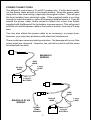
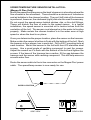
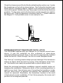
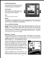
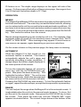
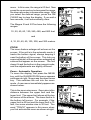
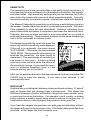
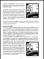
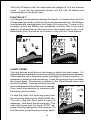
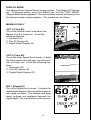
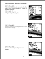
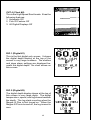
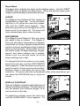
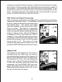
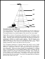
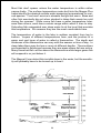
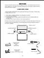
Magna III
and
Magna III Plus
INSTALLATION AND OPERATION
INSTRUCTIONS
TM
1
TABLE OF CONTENTS
INTRODUCTION ............................................................................................. 3
SPECIFICATIONS ........................................................................................... 3
INSTALLATION ............................................................................................... 4
INSTALLATION - Bracket ............................................................................... 4
POWER CONNECTIONS ............................................................................... 5
SPEED/TEMP SENSOR (MAGNA III PLUS ONLY) ....................................... 6
MAGNA III PORTABLE ................................................................................... 7
TRANSDUCER ................................................................................................ 9
KEYBOARD BASICS ...................................................................................... 10
DISPLAY ......................................................................................................... 10
OPERATION ................................................................................................... 11
MENUS ........................................................................................................... 11
AUTOMATIC ................................................................................................... 11
RANGE ........................................................................................................... 11
ZOOM ............................................................................................................. 12
SENSITIVITY .................................................................................................. 14
GRAYLINE® ................................................................................................... 14
FISH ID ........................................................................................................... 15
FISH TRACK™ ............................................................................................... 16
CHART SPEED .............................................................................................. 16
DISPLAY MODE ............................................................................................. 17
ALARMS ......................................................................................................... 20
BACK LIGHT .................................................................................................. 21
FEET/METER ................................................................................................. 21
DISPLAY CONTRAST .................................................................................... 21
ASP (Advanced Signal Processing) ............................................................... 22
SIMULATOR ................................................................................................... 22
TRANSDUCER CONE ANGLES .................................................................... 23
SURVEYING A LAKE ..................................................................................... 24
FISH ARCHES ................................................................................................ 24
WATER TEMPERATURE AND THERMOCLINES ........................................ 25
TROUBLESHOOTING ................................................................................... 27
WARRANTY ................................................................................................... 31
UPS RETURN SERVICE - U.S.A. ONLY ....................................................... 32
MISSING PARTS INFORMATION ................................................................. 34
HOW TO OBTAIN SERVICE - INTERNATIONAL ONLY .............................. 35
Copyright © 1995,1996, Eagle Electronics
All features and specifications in this manual are subject to change
without notice.
All screens in this manual are simulated.
Eagle Electronics
PO Box 669
Catoosa, OK 74015
2
INTRODUCTION
Thank you for purchasing an Eagle sonar. Your Magna or Magna III Plus
is a high quality sonar designed for both professional and novice fishermen. These units have an automatic feature that finds and displays the
bottom, fish, structure, and more! All you have to do is press the on key.
However, if you wish to fine tune the unit, all you have to do is press the
menu key. The Magna series has powerful features available through
easy-to-use menus.
To get started with your Eagle unit, first read the installation section. This
is where it all begins. Improper installation can cause problems down the
road. After you’ve read the instructions, install the unit, then read the rest
of the manual. The more you know about your unit, the better it will perform
for you. Take this manual for reference when you head for the water.
SPECIFICATIONS
Dimensions ...................... 5.9" W x 5.35" H x 3.4" D
Input Voltage .................... 10 - 15 vDC
Current Drain ................... 350 ma (lights off)
........................... 500 ma (lights on)
Transmitter
Frequency .......... 192 kHz
Output Power ..... 275 watts (peak-to-peak) (typical)
........................... 34.4 watts (RMS)
Display ........................... 100 pixels (H) x 65 pixels (W)
........................... Supertwist Liquid Crystal Display
3.4"
5.35"
5.9"
NOTICE!
The storage temperature for your unit is from -4 degrees to +167 degrees
Fahrenheit (-20 degrees to +75 degrees Celcius). Extended storage in temperatures higher or lower than specified will damage the liquid crystal display in your
unit. This type of damage is not covered by the warranty. For more information,
contact the factory customer service department or your local service center.
3
INSTALLATION - Bracket
You can install the Magna III on the top of a dash or from an overhead with
the supplied bracket. It can also be installed in the dash with an optional
IDA-3 mounting kit. If you use the supplied bracket, you may be interested
in the optional GBSA-1 swivel bracket kit. This converts the Magna III's
gimbal bracket to a swivel mount which can be used on the dash or
overhead mounting positions. Installation instructions for the in-dash and
swivel mounting kits are supplied with the adapter kits.
Mount the Magna III in any convenient location, provided there is clearance
when it’s tilted for the best viewing angle. Holes in the bracket’s base allow
wood screw or through bolt mounting. It may be necessary to place a piece
of plywood on the back side of thin panels to reinforce the panel. Make
certain there is enough room behind the unit to attach the power and
transducer cables.
Drill a hole in the dash for the power and transducer cables. The best
location for this hole is immediately under the gimbal bracket. This way, the
bracket covers the hole. The smallest hole the Magna IIII's power and
transducer cable connectors can pass through is 3/4". However, you can’t
pass a power or transducer connector and another cable through a 5/8"
hole. Therefore, after drilling the hole, pass the transducer connector up
through the hole from under the dash. Then drop the power cable down
from the front side of the dash. After installing the transducer, route its
cable to the unit by passing it through the hole from under the dash. Slide
the bracket over the hole, then route the transducer and power cables out
the slot in the back of the bracket. Finally, fasten the bracket to the dash.
MAGNA III
GIMBAL BRACKET
RUBBER WASHER
PLASTIC WASHER
(PORTABLE UNITS ONLY)
GIMBAL KNOB
Attach the Magna III to the gimbal bracket using the supplied gimbal knobs
and washers as shown above.
4
POWER CONNECTIONS
The Magna III works from a 12 volt DC system only. For the best results,
run the power cable directly to the boat’s battery. Keep the power cable
away from other boat wiring, especially the engine’s wires. This will give
the best isolation from electrical noise. If the supplied cable is not long
enough to reach the battery, splice #18 gauge insulated wire to it. If you do
extend the power cable, make certain to attach the in-line fuse holder
supplied with the Magna III to the battery or power source. This will protect
both the unit and the power cable in the event of a short. Use only a 3-amp
fuse.
You can also attach the power cable to an accessory or power buss,
however, you may have problems with electrical interference.
These units have reverse polarity protection. No damage will occur if the
power wires are reversed. However, the unit will not work until the wires
are attached correctly.
MAGNA III
WIRING
RED
WIRE
3 amp
FUSE
BLACK
WIRE
12 VOLT
BATTERY
RED
WIRE
3 amp
FUSE
BLACK
WIRE
MAGNA III PLUS
WIRING
TO
SPEED/
TEMP
SENSOR
12 VOLT
BATTERY
5
SPEED/TEMPERATURE SENSOR INSTALLATION (Magna III Plus Only)
Mount the speed/temp sensor on the boat’s transom in a location where the
flow of water is the smoothest. There should be a minimum of turbulence
and air bubbles in the chosen location. The port (left) side of the transom
is preferred, however, the starboard (right) side can be used if necessary.
Do not mount the speed sensor behind strakes, ribs, or thru-hull fittings.
These will disturb the flow of water to the speed sensor. In a typical
installation, the speed sensor is mounted six to twelve inches from the
centerline of the hull. The sensor must always be in the water to function
properly. Make certain the chosen location is in the water even at high
speed or when the boat is on plane.
Once you determine the proper location, place the sensor on the transom.
Make certain the sensor’s bottom is flush with the bottom of the hull. Mark
the transom in four places, two in each slot. Drill a 5/32" mounting hole at
each location. Mount the sensor to the hull with four #10 stainless steel
screws. Use a good grade of caulking compound to seal the screws.
Adjust the sensor so it is flush with the bottom of the hull and tighten the
screws. If the base of the transom has a radius, fill the gap between the
transom and the sensor with caulking compound. This will help ensure a
smooth water flow.
Route the sensor cable to the in-line connector on the Magna Plus’ power
cable. The speed/temp sensor is now ready for use.
GOOD LOCATION
SIDE VIEW
REAR VIEW
6
MAGNA III PORTABLE ASSEMBLY
INSTALLING THE BATTERIES
Release the latch on the front of the battery case. Open the compartment
and install four "D" cell batteries into the adapter. For the longest life, we
recommend you use alkaline batteries. This battery case will also hold one
rechargable battery instead of the "D" cells. See the enclosed coupon for
more information on the rechargable battery.
"D" CELL BATTERY
After installing the batteries, close the case and plug the power cable on
the battery case into the Magna III Portable. Plug the adapter cable into
the back of the sonar unit. Turn the sonar unit on. If it doesn't work, make
certain the battery terminals are making good contact against the battery
contacts. Also check the wiring connections on the D-cell battery adapter.
The red wire on the power cable should be attached to the red wire on the
D-cell battery adapter and the power cable's black wire should be connected to the black wire on the D-cell battery adapter. If it still doesn't work,
7
check the battery voltage. Most of the complaints we receive about
portable units result from stale batteries. Make certain the ones you buy
are fresh. Always remove batteries from the battery compartment before
storing the unit as dead batteries can leak and corrode the contacts.
In cold weather the efficiency of dry cell batteries drops with the temperature. We find it a good idea to have the Magna III Portable good and warm
along with the batteries before we leave home. If the batteries do lose a
charge, you can sometimes restore them by placing them in a warm room
or car interior. A better way is to replace them with batteries that have been
kept warm. Don't ever heat the batteries over an open flame or direct hot
air onto them. A fire or explosion could result.
PORTABLE TRANSDUCER ASSEMBLY
Assemble the transducer and bracket as shown below. Attach the
transducer to the bracket with the supplied hardware. Make certain there
is one washer on each side of the transducer, inside the bracket. Slide the
other washer over the end of the bolt and thread the nut onto it. Screw the
suction cup onto the bracket using the supplied screw and flat washer. Tie
the nylon cord through the hole in the top of the bracket. When using this
transducer, tie the other end of the nylon cord to the boat. This will help
prevent the loss of the transducer if it comes off the boat.
TIE
NYLON
CORD
HERE
SCREW
BOLT
WASHER
NUT
WASHER
8
Clean the chosen area of the hull before attaching the suction cup. Locate
the transducer on the hull as shown below. Don't allow the bracket to go
below the hull, as water pressure against it can cause the suction cup to
come off at speed. Moisten the cup, then press it onto the hull as firmly as
possible. Tie the nylon cord to the boat and route the transducer cable to
the sonar unit. Plug the transducer connector into the "Y" power cable on
the Magna III. Your portable sonar is now ready for use.
HULL
PERMANENT MOUNT TRANSDUCER INSTALLATION
The HS-WSBK supplied with your Magna III is a transom mount transducer. It can be installed on any outboard or stern-drive
(inboard\outboard) powered boat. It can also be permanently installed
inside the boat to "shoot-through" the hull on some fiberglass boats.
The “kick-up” mounting bracket helps prevent damage if the transducer
strikes an object while the boat is moving. If the transducer does “kickup”, the bracket can easily be pushed back in place without tools.
Read the enclosed transducer installation manual carefully before attempting the installation. Determine which of the mounting positions is
right for your boat. Use extreme care if mounting the transducer inside
the hull, since once it is epoxied into position, the transducer usually
cannot be removed. Remember, the transducer location is the most
critical part of a sonar installation. If it isn’t done properly, the sonar can’t
perform at it’s designed potential.
9
KEYBOARD BASICS
The unit sounds a tone when you
press any key. This tells you the
unit has accepted a command.
ON/CLEAR
Use this key to turn the unit on. It
also clears menu selections and
the menus from the screen.
OFF
This key turns the unit off.
MENU
The Magna III and Magna III Plus have many features that are accessed
with this key. To see the first menu, press the MENU key. To see the other
menus, press the MENU key repeatedly.
UP and DOWN ARROWS
Use these keys to adjust virtually every feature and function on the unit.
NOTE: The up arrow key also stops the chart when no menus are
displayed. In other words, anytime you wish to stop the chart, first make
certain no menu is on the screen. Now press the up arrow key. The chart
freezes and the word “STOP” appears at the top of the screen. To start the
chart, press the up arrow key again.
DISPLAY - General
The lights flash for about ten seconds when the Magna III is turned on.
Three menus appear, one after the other. The menus are the lights
(LAMP), feet-meter selection (FEET/METER), and contrast adjustment
(DARK/LIGHT). To turn the lights on, press
the up arrow key. To switch from feet to
meters, press the down arrow key when the
proper menu appears. To adjust the contrast,
wait for the DARK/LIGHT menu to appear.
Now press the up arrow key to darken the
screen, the down arrow to lighten it. The
menus disappear after a few seconds. If you
don’t want to wait, press the ON/CLEAR key
to clear the menus from the screen.
When the Magna III is first turned on, the
display appears similar to the one at right.
The unit is in the automatic mode and the Fish
10
ID feature is on. The depth range displays on the upper left side of the
screen. On the screen at the bottom of the previous page, the range is from
0 to 60 feet and the bottom depth is 37.3 feet.
OPERATION
MENUS
The Magna III and Magna III Plus use menus to guide you through the unit’s
functions and features. The menu key accesses these features, allowing
you to customize the unit to your particular needs and water conditions. All
you have to do to leave one menu and enter another is press the menu key
repeatedly. If you ever get lost in the menus, simply press the ON/CLEAR
key. This clears the menus from the screen.
Menus change depending on the mode the unit is in. For example, if the
automatic mode is turned off, the sensitivity menu changes from “AUTO
SENS” to “MAN SENS.” Other messages may appear in menu boxes or
new menus can appear, again depending on previous selections.
On the screen shown on the previous page, the lamp menu is showing.
AUTOMATIC
When the Magna III is first turned on, the
automatic feature is enabled. This feature
automatically adjusts the unit’s range and
sensitivity according to water conditions. It
always keeps the bottom depth displayed in
the lower portion of the screen.
To turn the automatic feature off, press the
menu key until the AUTO/MAN menu appears. Now press the down arrow key. This
highlights the letters “MAN.” The unit is now
in the manual mode. Wait a few seconds and
the menu will scroll off the screen’s left side.
Pressing the ON/CLEAR key also clears it. To turn the automatic feature
on again, repeat the above steps, except this time press the up arrow key.
RANGE
You can’t adjust the range when the Magna III is in the automatic mode. It
is adjustable when the unit is in the manual mode, however. To do so, first
put the unit in the manual mode. Now press the ON/CLEAR key to clear
the screen. Then press the menu key until the “RANGE SEL” menu
appears as shown below. The current range shows at the bottom of the
11
menu. In this case, the range is 60 feet. Now
press the up arrow key to decrease the range,
the down arrow key increases the range. After
you select the desired range, press the ON/
CLEAR key to clear the display. If you wait a
few seconds, it will automatically clear.
The Magna III and III Plus have the following
ranges:
10, 20, 40, 60, 120, 240, 480, and 900 feet.
and
5, 10, 20, 40, 60, 100, 200, and 300 meters.
ZOOM
The zoom feature enlarges all echoes on the
screen. If the unit is in the automatic mode, it
tracks the bottom signal, always keeping it
near the bottom of the screen. This lets you
see small detail, at the same time enlarging all
echoes that appear on the screen. The unit
doesn’t track the bottom in the manual mode,
and the adjustments are slightly different.
Zoom - Automatic Operation
To zoom the display, first press the MENU
key until the RANGE/ZOOM menu appears
as shown at right. Now press the down arrow
key. This switches the unit into the zoom
mode. A new menu immediately appears as
shown below.
This is the zoom size menu. Zoom size is the
distance between the upper limit and the
lower limit. The upper limit shows at the top
left corner of the screen. The lower limit is in
the bottom left corner. For example, if the
upper limit is 40 feet and the lower limit is 70
feet, the zoom window size is 30 feet. The
word “TRACK” appears in this menu when
you first activate the zoom as shown at right.
12
This means the Magna III is tracking the
bottom in a zoom window, always keeping it
on the display.
Press the up arrow key to decrease the
zoom size, press the down arrow key to
increase the zoom size.
When the unit is switched into the zoom
mode, the letters “ZM” appear at the top of
the screen. The zoom window size displays
in the top right corner of the screen.
On the screen shown above, the zoom size has been changed to 20 feet.
To turn the zoom feature off, press the menu key until the RANGE/ZOOM
menu appears. Now press the up arrow key. This switches the unit into
the range mode, which turns the zoom feature off.
The Magna III and III Plus have the following zoom ranges:
10, 20, 30, 60, 120, 240, and 480 feet
and
5, 10, 20, 30, 50, 100, and 150 meters.
Zoom - Manual Operation
To operate the zoom feature when the Magna III is in the manual mode, first
press the menu key. Then press the down arrow key in the RANGE/ZOOM
menu to place the Magna in the zoom mode. The zoom size menu
automatically appears next. You can change the zoom size by pressing
the up or down arrows. After you select the desired zoom size, press the
menu key until the “MOVE ZOOM” menu appears. This menu lets you
move the zoom window up or down inone foot
increments by pressing the arrow keys. Thus,
you can move the zoom window up towards
the surface, down to the bottom, or anywhere
in between. The window stays where you put
it. It doesn’t track the bottom signal.
To turn the zoom feature off, press the menu
key until the RANGE/ZOOM menu appears.
Now press the up arrow key. This switches
the unit into the range mode, which turns the
zoom feature off.
13
SENSITIVITY
The sensitivity menu lets you control the unit’s ability to pick up echoes. A
low sensitivity level excludes much of the bottom information, fish signals,
and other detail. High sensitivity settings lets you see features, but it can
also clutter the screen with noise and other unwanted signals. Typically,
the best sensitivity level shows a good, solid bottom signal with grayline.
The Magna III adjusts the sensitivity level to keep a solid bottom signal on
the screen. It adds a little extra when it’s in the automatic mode. This gives
it the capability to show fish and other detail. However, situations occur
where it becomes necessary to increase or decrease the sensitivity level.
Typically, this occurs when you wish to see more detail, so you need to
increase the sensitivity. The procedure to adjust it is the same whether the
unit is in the automatic or manual mode.
To change the sensitivity level, first press the
menu key until the sensitivity menu appears.
If the unit is in automatic, the menu shows
“AUTO SENS.” Otherwise, the menu shows
“MAN SENS.” Now press the up arrow key to
increase the sensitivity, the down arrow to
decrease it. The percentage of sensitivity in
use shows in this menu. Echoes scrolling
onto the screen will also show the effects of
the sensitivity change. If you reach the maximum or minimum sensitivity level, a tone
sounds alerting you to the limits.
After you’ve adjusted the unit to the desired sensitivity level, press the ON/
CLEAR key to clear the display. If you wait a few seconds, it will
automatically clear.
GRAYLINE ®
Grayline lets you distinguish between strong and weak echoes. It “paints”
gray on targets that are stronger than a preset level. This shows the
difference between a hard or soft bottom, large fish versus smaller ones,
or rocks and brush on the bottom. For example, a soft, muddy, or weedy
bottom returns a weaker signal which shows a narrow or no gray line. A
hard bottom returns a strong signal that causes a wide gray line.
If you have two targets of equal size, one with gray and the other without,
the target with gray is the stronger echo. This helps distinguish fish from
structure, or the larger fish from a smaller one.
14
Grayline ® is adjustable. Since it shows the
difference between strong and weak echoes,
changing the level may require a different
sensitivity setting.
To change the Grayline level, first press the
MENU key until the Grayline menu appears.
Now press the up arrow key to increase the
level, the down arrow to decrease it. The
percentage of Grayline now in use shows in
this menu. Echoes scrolling onto the screen
will also show the effects of the Grayline
change. If you reach the maximum or minimum level, a tone sounds
alerting you to the limits.
The level chosen by the Magna III when it’s first turned on is usually
adequate for most conditions. Experiment with your unit to find the
Grayline setting that’s best.
FISH ID FEATURE
The Fish ID feature identifies targets that meet certain conditions as fish.
The microcomputer analyses all echoes and eliminates surface clutter,
thermoclines, and other undesirable signals. In most instances, remaining
targets are fish. The Fish ID feature displays symbols on the screen in
place of the actual fish echoes. There are four symbol sizes: tiny, small,
medium, and large. These show the relative size between targets. In other
words, it displays a small fish symbol when it thinks a target is a small fish,
a medium fish symbol on a larger target, etc.
The microcomputer is sophisticated, but it can be fooled. It can't distinguish between fish and other suspended objects such as turtles, submerged floats, air bubbles, etc. Individual tree limbs extending outwards
from a group of limbs are the hardest objects for the Fish ID feature to
distinguish from fish. You may see Fish ID
symbols on the screen when, in fact, there are
no fish. Practice with the unit when the Fish
ID feature is on and off to become more
familiar with Fish ID. When the Magna III is
first turned on, the Fish ID feature is automatically turned on, also. To turn this feature off,
press the menu key until the Fish ID feature’s
menu appears as shown at right. Now press
the down arrow key. This turns the feature off.
To turn it back on, repeat the above steps, but
press the up arrow key instead.
15
The Fish ID feature can’t be used when the Magna III is in the manual
mode. If you turn the automatic feature off, the Fish ID feature will
automatically be turned off, also.
FISH TRACK™
The Magna III automatically displays the depth of a target when the Fish
ID feature places a fish symbol on the screen as shown below. This feature
is automatically enabled when the Magna III is turned on. To turn it off or
on again, press the MENU key repeatedly until the Fish Track menu
appears as shown below. Now press the down arrow key to turn it off.
Remember, Fish ID must be on in order to use the Fish Track feature.
CHART SPEED
The rate echoes scroll across the screen is called the chart speed. It’s
adjustable by pressing the menu key until the chart speed menu appears.
Chart speed is set to maximum when the Magna III is first turned on. To
decrease it, press the down arrow key. Press the up arrow key to increase
the speed again. The percent numbers in the Chart Speed menu box
shows the speed. Echoes scrolling onto the
screen will also show the effects of the change.
If you reach the maximum or minimum level,
an warning tone sounds.
To stop the chart, first clear any menu from
the screen by pressing the ON/CLEAR key.
You can’t stop the chart while a menu is
displayed. Now press the up arrow key. The
chart will freeze and the word “STOP” appears at the top right portion of the screen. To
start the chart, press the up arrow key again.
16
DISPLAY MODE
The Magna III has three different screen modes. The Magna III Plus has
six. To change modes, press the MENU key until the “DISP MODE”
(Display Mode) menu appears. Then press the up or down arrow keys until
the desired mode number appears. The modes are as follows:
MAGNA III ONLY
CHT 1 (Chart #1)
This is the default mode used when the
Magna III is first turned on. It has the
following features:
1. Automatic On
2. Fish ID Feature On
3. Digital Depth Display On
CHT 2 (Chart #2)
This is the High Speed Scroll mode. It shifts
the chart speed into high gear, scrolling echoes at a high rate. It has the following features:
1. Automatic Off
2. Fish ID Feature Off
3. Digital Depth Display Off
DIG 1 (Digital #1)
This is the digital only screen. It shows the
digital depth display at the top of the screen in
very large numbers. The shallow and deep
alarm settings are displayed beneath the
digital depth. No chart shows on this screen.
17
DISPLAY MODE - MAGNA III PLUS ONLY
CHT 1 (Chart #1)
This is the default mode used when the Magna III Plus is first turned on. It has the
following features:
1. Automatic On
2. Fish ID Feature On
3. Digital Depth Display On
CHT 2 (Chart #2)
Same as Chart #1 plus digital surface water
temperature display.
CHT 3 (Chart #3)
Same as Chart #1 plus digital speed
display.
18
CHT 4 (Chart #4)
This is the High Speed Scroll mode. It has the
following features:
1. Automatic Off
2. Fish ID Feature Off
3. All Digital Displays Off
DIG 1 (Digital #1)
This is the first digital only screen. It shows
the digital depth display at the top of the
screen in very large numbers. The shallow
and deep alarm settings are displayed beneath the digital depth. No chart shows on
this screen.
DIG 2 (Digital #2)
The digital depth display shows at the top of
this screen in very large digits. The digital
temperature, speed, and log shows beneath
the depth. The log starts counting when the
Magna III Plus is first turned on. When the
Magna III Plus is turned off, the log is reset to
zero.
19
ALARMS
FISH ALARM
The Fish Alarm sounds a tone when a fish
symbol appears on the screen. To use the
fish alarm, press the menu key until the “FISH
ALARM” menu appears on the screen. Now
press the up arrow key to turn the alarm on.
Repeat the above steps to turn the fish alarm
off. (Note: If the Fish ID feature is off, it will be
turned on when you turn the fish alarm on.)
DEPTH ALARMS
The depth alarms are triggered only by the bottom signal. No other echoes
will activate these alarms. The depth alarms consist of a shallow and deep
alarm. The shallow alarm sounds an alarm tone when the bottom goes
shallower than the alarm’s setting. The deep alarm sounds a tone when
the bottom goes deeper than it’s setting. Both alarms adjust the same,
although through different menus.
Shallow Alarm
To set the shallow alarm, press the menu key
repeatedly until the “SHAL ALARM” menu
appears. Press the down arrow key to increase the shallow alarm's depth setting, the
up arrow key decreases it. The number in the
shallow alarm’s menu box shows the current
shallow alarm setting. When the number
reaches the desired setting, release the arrow key. When the bottom depth goes shallower than the alarm’s setting an alarm tone
sounds. At the same time the alarm sounds,
a message box appears on the screen as
shown at right.
Press the up arrow key to silence the alarm.
This will turn the alarm sound off until the
shallow alarm is triggered again.
To turn the alarm off, press the menu key until
the shallow alarm menu appears. Then press
the up arrow key until the word “OFF” appears.
20
Deep Alarm
The deep alarm adjusts the same as the shallow alarm. Use the “DEEP
ALARM” menu to adjust the deep alarm. When the bottom signal goes
deeper than the setting, an alarm tone sounds.
LIGHTS
The Magna III and Magna III Plus’ display is
backlighted for night use. To turn the backlights on or off, press the menu key repeatedly until the LAMP menu appears. Now
press the up arrow to turn the lights on or the
down arrow to turn them off. The menu will
clear automatically after a few seconds.
FEET/METER
The Magna III and Magna III Plus can show
the depth in feet or meters. The Magna III
Plus can also show temperature in degrees
Fahrenheit or Celsius, speed in statute miles
per hour or knots, and distance (log) in statute
miles or nautical miles. When either unit is in
the metric mode, all depth readings, ranges,
zooms, and alarm settings are in meters.
When a unit is in the feet mode, all of the
above settings are in feet.
To change from feet to meters or vice-versa,
press the menu key until the FEET/METER
menu appears. Press the down arrow key to
switch to metric, the up arrow to switch to feet.
Displays show in feet when the unit is first
turned on. The menu will clear automatically after a few seconds or you
can press the ON/CLEAR key to clear the
screen.
DISPLAY CONTRAST
The unit’s display contrast is adjustable to suit
different lighting conditions. This will help you
see the screen from different angles, or at
various times of the day.
To adjust the contrast, press the menu key
until the DARK/LIGHT menu appears. To
21
decrease it, press the down arrow key. Press the up arrow key to increase
the contrast. The bar graph in the Dark/Light menu box shows a graph of
the contrast. The screen will also show the effects of the change. If you
reach the maximum or minimum level, a tone sounds alerting you to the
limits. The menu will clear automatically after a few seconds or you can
press the ON/CLEAR key to clear the screen.
ASP (Advanced Signal Processing)
ASP is a program embedded in the Magna III’s computer that is specifically
designed to eliminate noise. It continually monitors the signals from the
receiver, determines which echoes are noise
and rejects them. This allows true target
echoes to display on the screen with a minimum of clutter. This feature is especially
useful since it typically lets you operate the
boat at all speeds without adjusting the sensitivity or other controls. When the Magna III
or Magna III Plus is first turned on, ASP is
enabled. To turn ASP off, press the menu key
repeatedly until the ASP menu appears. Now
press the up arrow to turn it on or the down
arrow to turn it off. The menu will clear
automatically after a few seconds or you can
press the ON/CLEAR key to clear the screen.
SIMULATOR
The Magna III and Magna III Plus have a
simulator built into them that can show a
simulated bottom signal with fish signals. All
features of the Magna III work normally when
the simulator is in use. You can change the
range, zoom, and use the alarms as desired.
To use the simulator, press the menu key
repeatedly until the SONAR SIM menu appears. Now press the up arrow to turn it on.
Repeat the above steps to turn it off, or turn
the unit off and back on again.
22
25'
50'
75'
100'
8 DEGREE
20 DEGREE
TRANSDUCER CONE ANGLES
The sound waves from the transducer spread out into the water in a
cone shaped beam. This looks much like the beam from a flashlight.
The angle between the outside edges of the cone is the cone angle.
Eagle offers a choice of transducers with either an 8 or 20 degree cone
angle. The transducer supplied with the Magna III has a 20 degree cone
angle. Typically, wide cone angle transducers (20 degrees) are ideal for
operating in shallow to medium water depths. The 20 degree cone
angle allows you to see more of the underwater world. In 15 feet of
water the 20 degree cone covers an area about six feet across. The 8
degree transducer covers only about a two foot circle.
The 20 degree transducer is almost always the best to use in fresh
water, the 8 degree mostly in salt water. In a deep water environment,
(300 feet - fresh water, 100 feet - salt water) the narrow cone angle is
more desirable. Since the sound energy is concentrated in a smaller
area, it can penetrate to much deeper depths. Both 8 degree and 20
degree transducers give accurate bottom readings, even though the
bottom signal is much wider on the 20 degree model. This is because
you are seeing more of the bottom. Remember, the shallow edge of the
signal shows you the true depth. The rest of the signal tells you whether
you are over rocks, mud, etc.
23
SURVEYING A LAKE
The most successful anglers on any body of water are those who fish it
day after day and year after year. Eventually, they learn the hot spots
that produce fish consistently. They discover through experience
where, and at what depth, they can expect to find the fish they want at
any season. And they realize that these productive areas change
throughout the year depending on water level, temperature, food, and
other factors.
With the Magna III, anyone can eliminate guesswork and concentrate on
the areas where fish are likely to be. Even if it’s the first time on the lake!
The most efficient way to become acquainted with a body of water is to
survey it with your Magna III Start with a map of the lake, if possible, and
indicate the promising spots in relation to landmarks on shore. Keep a
few marker buoys in the boat, ready to toss overboard. When the
Magna III indicates a school of fish, throw the buoy out. With the school
thus marked, you can make your turn and come back to fish in exactly
the right spot. This is essential when you’re far from shore on a big lake.
Unless you mark the school of fish when you’re over it, you may not be
able to find it again.
FISH ARCHES
Fish arches are created when the cone of sound passes over a fish.
The distance to a fish when the cone first strikes it is shown as "A" on the
next page. When the center of the cone strikes the fish, the distance is
shorter as shown "B". As the cone leaves the fish, the distance increases again as shown in "C".
When the Fish I.D. mode is off, the depth of the water will affect the size
and shape of the fish arch due to the cone angle diameter. For example,
if the cone passes over a fish in shallow water, the signal displayed on
the Magna III may not arch at all. This is due to the narrow cone
diameter and the resolution limitations of the display.
Very small fish probably will not arch at all. Medium sized fish will show
a partial arch, or a shape similar to an arch if they’re in deep water.
Large fish will arch, but turn the sensitivity up in deeper water to see the
arch. Because of water conditions, such as heavy surface clutter,
thermoclines, etc., the sensitivity sometimes cannot be increased
enough to get fish arches.
24
BOAT'S DIRECTION OF TRAVEL
A
C
B
A
B
C
One of the best ways to get fish arches is to expand or “zoom” a
segment of the water. For example, from 45 to 60 feet. The smaller the
segment, the better the screen resolution will be. The easiest way to do
this on the Magna III is with the Zoom feature. This feature expands the
echoes, making it easier to see detail. For the best results, turn the
sensitivity up as high as possible without getting too much noise on the
screen. In medium to deep water, this method should work to display
fish arches.
If you see fish signals when the unit is in the manual mode, but don't get
fish symbols when the Fish I.D. feature is on, try increasing the
sensitivity's level.
WATER TEMPERATURE AND THERMOCLINES
Water temperature has an important-if not controlling-influence upon the
activities of all fish. Fish are cold blooded and their bodies are always
the temperature of the surrounding water. During the winter, colder
water slows down their metabolism. At this time, they need about a
fourth as much food as they consume in the summer.
25
Most fish don’t spawn unless the water temperature is within rather
narrow limits. The surface temperature meter built into the Magna Plus
helps identify the desired surface water spawning temperatures for various species. Trout can’t survive in streams that get too warm. Bass and
other fish eventually die out when stocked in lakes that remain too cold
during the summer. While some fish have a wider temperature tolerance than others, each has a certain range within which it tries to stay.
Schooling fish suspended over deep water lie at the level that provides
this temperature. We assume they are the most comfortable here.
The temperature of water in the lake is seldom constant from top to
bottom. Layers of different temperatures form, and the junction of a
warm and cool layer of water is called a thermocline. The depth and
thickness of the thermocline can vary with the season or time of day. In
deep lakes there may be two or more at different depths. Thermoclines
are important to fishermen because they are areas where fish are active.
Many times bait fish will be above the thermocline while larger game fish
will suspend in or just below it.
The Magna III can detect this invisible layer in the water, but the sensitivity will probably have to be turned up to see it.
SURFACE LAYER
ABSORBS HEAT
FROM THE SUN
EPILIMNION
THERMOCLINE
MOST PRODUCTIVE
ZONE FOR FISHING
HYPOLIMNION
26
IMPORTANT INFORMATION!
If your unit is not working, or if you need technical help, please use the
following troubleshooting section before contacting the factory customer
service department. It may save you the trouble of returning your unit.
TROUBLESHOOTING
Unit won’t turn on:
1. Check the power cable’s connection at the unit. Also check the wiring.
2. Make certain the power cable is wired properly. The red wire connects
to the positive battery terminal, black to negative or ground.
3. Check the fuse.
4. Measure the battery voltage at the unit’s power connector. It should be
at least 11 volts. If it isn’t, the wiring to the unit is defective, the battery
terminals or wiring on the terminals are corroded, or the battery needs
charging.
Unit freezes, locks up, or operates erratically:
1. Electrical noise from the boat’s motor, trolling motor, or an accessory
may be interfering with the sonar unit. Rerouting the power and transducer
cables away from other electrical wiring on the boat may help. Route the
sonar unit’s power cable directly to the battery instead of through a fuse
block or ignition switch
2. Inspect the transducer cable for breaks, cuts, or pinched wires.
3. Check the transducer and power connector. Make certain it's securely
plugged in to the unit.
Weak bottom echo, digital readings erratic, or no fish signals:
1. Make certain transducer is pointing straight down. Clean the face of the
transducer. Oil, dirt, and fuel can cause a film to form on the transducer,
reducing its effectiveness. If the transducer is mounted inside the hull, be
sure it is shooting through only one layer of fiberglass and that it is securely
bonded to the hull. Do NOT use RTV silicone rubber adhesive or
MarinetexTM.
2. Electrical noise from the boat’s motor can interfere with the sonar. This
causes the sonar to automatically increase its Discrimination or noise
rejection feature. This can cause the unit to eliminate weaker signals such
as fish or even structure from the display.
27
3. The water may be deeper than the sonar’s ability to find the bottom. If
the sonar can’t find the bottom signal while it’s in the automatic mode, the
digital will flash continuously. It may change the range to limits far greater
than the water you are in. If this happens, place the unit in the manual
mode, then change the range to a realistic one, (for example, 0-100 feet)
and increase the sensitivity. As you move into shallower water, a bottom
signal should appear.
4. Check the battery voltage. If the voltage drops, the unit’s transmitter
power also drops, reducing its ability to find the bottom or targets.
Bottom echo disappears at high speeds or erratic digital reading or
weak bottom echo while boat is moving
1. The transducer may be in turbulent water. It must be mounted in a
smooth flow of water in order for the sonar to work at all boat speeds. Air
bubbles in the water disrupt the sonar signals, interfering with its ability to
find the bottom or other targets. The technical term for this is ‘Cavitation’.
2. Electrical noise from the boat’s motor can interfere with the sonar. This
causes the sonar to automatically increase its Discrimination or noise
rejection feature. This can cause the unit to eliminate weaker signals such
as fish or even structure from the display. Try using resistor spark plugs
or routing the sonar unit’s power and transducer cables away from other
electrical wiring on the boat.
No fish arches when the Fish ID feature is off:
1. Make certain transducer is pointing straight down. This is the most
common problem if a partial arch is displayed. See the Fish Arch section
in your owner's manual for more information.
2. The sensitivity may not be high enough. In order for the unit to display
a fish arch, it has to be able to receive the fish’s echo from the time it enters
the cone until it leaves. If the sensitivity is not high enough, the unit displays
the fish only when it is in the center of the cone.
3. Use the Zoom feature. It is much easier to display fish arches when
zoomed in on a small range of water than a large one. For example, you
will have much better luck seeing fish arches with a 30 to 60 foot range than
a 0 to 60 foot range. This enlarges the targets, allowing the display to show
much more detail.
28
4. The boat must be moving at a slow trolling speed to see fish arches. If
the boat is motionless, fish stay in the cone, showing on the display as
straight horizontal lines.
ELECTRICAL NOISE
A major cause of sonar problems is electrical noise. This usually appears
on the sonar’s display as random patterns of dots or lines. In severe cases,
it can completely cover the screen with black dots, or cause the unit
operate erratically, or not at all.
To eliminate or minimize the effects of electrical noise, first try to determine
the cause. With the boat at rest in the water, the first thing you should do
is turn all electrical equipment on the boat off. Make certain the engine is
off, also. Turn your Magna III on, then turn off ASP (Advanced Signal
Processing). There should be a steady bottom signal on the display. Now
turn on each piece of electrical equipment on the boat and view the effect
on the sonar’s display.
For example, turn on the bilge pump and view the sonar display for noise.
If no noise is present, turn the pump off, then turn on the VHF radio and
transmit. Keep doing this until all electrical equipment has been turned on,
their effect on the sonar display noted, then turned off.
If you find noise interference from an electrical instrument, trolling motor,
pump, or radio, try to isolate the problem. You can usually reroute the sonar
unit’s power cable and transducer cable away from the wiring that is
causing the interference. VHF radio antenna cables radiate noise when
transmitting, so be certain to keep the sonar’s wires away from it. You may
need to route the sonar unit’s power cable directly to the battery to isolate
it from other wiring on the boat.
If no noise displays on the sonar unit from electrical equipment, then make
certain everything except the sonar unit is turned off, then start the engine.
Increase the RPM with the gearshift in neutral. If noise appears on the
display, the problem could be one of three things; spark plugs, alternator,
or tachometer wiring. Try using resistor spark plugs, alternator filters, or
routing the sonar unit’s power cable away from engine wiring. Again,
routing the power cable directly to the battery helps eliminate noise
problems. Make certain to use the in-line fuse supplied with the unit
when wiring the power cable to the battery!
When no noise appears on the sonar unit after all of the above tests, then
the noise source is probably cavitation. Many novices or persons with
limited experience make hasty sonar installations which function perfectly
29
in shallow water, or when the boat is at rest. In nearly all cases, the cause
of the malfunction will be the location and/or angle of the transducer. The
face of the transducer must be placed in a location that has a smooth flow
of water at all boat speeds. Read your transducer owner’s manual for the
best mounting position.
30
EAGLE ELECTRONICS
FULL ONE-YEAR WARRANTY
“We", “our”, or “us” refers to EAGLE ELECTRONICS, a division of LEI, the manufacturer of
this product. “You” or “your” refers to the first person who purchases this product as a
consumer item for personal, family, or household use.
We warrant this product against defects or malfunctions in materials and workmanship, and
against failure to conform to this product’s written specifications, all for one year (1) from the
date of original purchase by you. WE MAKE NO OTHER EXPRESS WARRANTY OR
REPRESENTATION OF ANY KIND WHATSOEVER CONCERNING THIS PRODUCT.
Your remedies under this warranty will be available so long as you can show in a reasonable
manner that any defect or malfunction in materials or workmanship, or any non-conformity
with the product’s written specifications, occurred within one year from the date of your
original purchase, which must be substantiated by a dated sales receipt or sales slip. Any
such defect, malfunction, or non-conformity which occurs within one year from your original
purchase date will either be repaired without charge or be replaced with a new product
identical or reasonably equivalent to this product, at our option, within a reasonable time after
our receipt of the product. If such defect, malfunction, or non-conformity remains after a
reasonable number of attempts to repair by us, you may elect to obtain without charge a
replacement of the product or a refund for the product. THIS REPAIR, REPLACEMENT, OR
REFUND (AS JUST DESCRIBED) IS THE EXCLUSIVE REMEDY AVAILABLE TO YOU
AGAINST US FOR ANY DEFECT, MALFUNCTION, OR NON-CONFORMITY CONCERNING THE PRODUCT OR FOR ANY LOSS OR DAMAGE RESULTING FROM ANY OTHER
CAUSE WHATSOEVER. WE WILL NOT UNDER ANY CIRCUMSTANCES BE LIABLE
TO ANYONE FOR ANY SPECIAL, CONSEQUENTIAL, INCIDENTAL, OR OTHER INDIRECT DAMAGE OF ANY KIND.
Some states do not allow the exclusion or limitation of incidental or consequential damages,
so the above limitations or exclusions may not apply to you.
This warranty does NOT apply in the following circumstances: (1) when the product has
been serviced or repaired by anyone other than us, (2) when the product has been
connected, installed, combined, altered, adjusted, or handled in a manner other than
according to the instructions furnished with the product, (3) when any serial number has
been effaced, altered, or removed, or (4) when any defect, problem, loss, or damage has
resulted from any accident, misuse, negligence, or carelessness, or from any failure to
provide reasonable and necessary maintenance in accordance with the instructions of the
owner’s manual for the product.
We reserve the right to make changes or improvements in our products from time to time
without incurring the obligation to install such improvements or changes on equipment or
items previously manufactured.
This warranty gives you specific legal rights and you may also have other rights which may
vary from state to state.
REMINDER: You must retain the sales slip or sales receipt proving the date of your original
purchase in case warranty service is ever required.
31
Eagle's UPS Return Service
Eagle Electronics and United Parcel Service (UPS) are proud to offer all
of our customers free shipping for all units sent to us for repair or service.
If you have to send this unit to the factory, and you are in the continental
United States, use the enclosed UPS shipping label for easy, free shipping
to our factory customer service department. There are six easy steps:
1.Call Eagle at the toll-free number on the front of this flyer for a Return
Authorization (RA) number and instructions about what accessories to
return. Do not return a product to the factory without a Return
Authorization (RA) Number!
2.Pack your unit and any accessories in the original shipping container, if
possible. Be sure to include proof of purchase for warranty verification!
3. Write a brief note detailing the problem you're having with the unit.
Please include your name, address, and daytime telephone number.
4. Please include payment for non-warranty repairs. Check, money order,
Visa, or MasterCard may be used.
5.Fill in your name, address, zip code, date, and RA number in the blanks
provided on the UPS form included with your unit.
6.Attach the label to the shipping box, tear off the tab for your receipt and
give the package to any UPS driver or take the package to any UPS
Customer Center. You will not be charged for this shipment.
That's it! Your unit will be shipped to Eagle's customer service department
at no charge to you. Our normal in-plant turnaround on repairs is 3 working
days. Units under warranty will be returned to you at no charge.
NOTE!
Eagle will pay UPS surface shipping charges both to and from the factory
for this unit in the event it needs repair. Your unit is insured against loss
or shipping damage when you use the enclosed UPS label.
32
KEEP THIS LABEL!
YOU WILL NEED IT IF YOU EVER NEED TO RETURN YOUR UNIT TO THE
FACTORY FOR REPAIR.
This UPS shipping offer is good only in the continental United States (excludes Alaska and Hawaii).
Eagle Electronics may find it necessary to change or end our shipping policies, regulations,
and special offers at any time. We reserve the right to do so without notice.
Accessory Ordering Information
To order accessories such as power cables or transducers, please contact:
1) Your local marine dealer. Most quality dealers that handle marine
electronic equipment should be able to assist you with these items.
Consult your local telephone directory for listings.
2) LEI Extras, Inc. P.O. Box 129 Catoosa, OK 74015-0129
or call
800-324-0045
(USA orders only.)
33
NOTICE!
Please check the items in the box against this list. You should have all of the
items shown on this page. If you are missing any of the items, please call our
special toll-free number:
1-800-324-1353
A RECORDED MESSAGE will request the following information. Please have
it ready before you call.
1. Your name, shipping address, and telephone number.
2. The part that's missing.
3. The model, serial number, and DATE AND PLACE OF PURCHASE OF
YOUR UNIT.
4. The best time of day to call you if we have questions.
Provided that all of the requested information is recorded and approved by our
Customer Service Department, the missing item(s) will be shipped directly to
you free of charge.
DISPLAY UNIT
RUBBER WASHER
RUBBER WASHER
GIMBAL KNOB
GIMBAL KNOB
GIMBAL BRACKET
TRANSDUCER,
BRACKET,
AND
HARDWARE
POWER CABLE
SPEED/TEMP
SENSOR
(Magna III Plus models Only)
34
FUSE
FUSE HOLDER
How to Obtain Service
(Canadian Customers Only)
We back your investment in quality products with quick, expert service and genuine Eagle
replacement parts. If you need service or repairs, contact the Eagle Factory Customer
Service Department at the toll-free number listed below. A technician may be able to solve
the problem and save you the inconvenience of returning your unit. You will be asked for your
unit's serial number.
800-324-1354
Canada Only. Monday through Friday 8:00 A.M. - 8:00 P.M. Central Time.
How to Obtain Service
(International Customers Only)
If you need service or repairs, contact the dealer in the country you purchased your unit.
WARRANTY REPAIR WILL BE HONORED ONLY IN THE COUNTRY
UNIT WAS PURCHASED.
Please follow the shipping instructions shown below on this page if you have to mail your
unit to the dealer. For proper testing, repair, and service, send a brief note with the product
describing the problem. Be sure to include your name, return shipping address, and a
daytime telephone number.
Shipping Information
When sending a product for repair, we recommend you do the following:
1. Always use the original shipping container and filler material the product was packed
in when shipping your product.
2 Always insure the parcel against damage or loss during shipment. Eagle does not
assume responsiblity for goods lost or damaged in transit.
3. For proper testing, repair, and service, send a brief note with the product describing the
problem. Be sure to include your name, return shipping address, and a daytime
telephone number.
Accessory Ordering Information
To order accessories such as power cables or transducers, please contact:
1. Your local marine dealer. Most quality dealers that handle marine electronic equipment
should be able to assist you with these items. Consult your local telephone directory for
listings.
2. Canadian customers only can write:
Lowrance/Eagle Canada, 919 Matheson Blvd., E. Mississauga, Ontario L4W2R7
or fax 416-629-3118
35
Your unit's serial number
How to Obtain Service
(U.S.A. Only)
We back your investment in quality products with quick, expert service and
genuine Eagle™ replacement parts. If you're in the United States and you
have questions, please contact the Factory Customer Service Department
using our toll-free number listed below. You must send the unit to the
factory for warranty service or repair. Please call the factory before sending
the unit. You will be asked for your unit's serial number (shown above). Use
the following toll-free number:
800-324-1354
U.S.A.only. Monday through Friday 8:00 A.M. - 8:00 P.M. Central time, except holidays.
Your unit is covered by a full one-year warranty. (See inside for complete
warranty details.) If your unit fails and the failure is not covered by the
original warranty, Eagle has a flat-rate repair policy that covers your unit
and accessories packed with the unit at the factory. There is a 180-day
warranty on all non-warranty repairs from the factory, which is similar to the
original warranty, but is for 180 days rather than one year. For further
details, please call us at the above number.
On factory repairs, we guarantee your unit will be repaired in three working
days from the time it is received. This does not include shipping time. If for
some reason we cannot meet this commitment, we will extend your
warranty for another full year, free of charge, from the date of repair.
Eagle also gives you free UPS shipping from anywhere in the continental
United States both to and from the factory for all warranty repairs. You can
also use the enclosed UPS shipping label for non-warranty shipments. See
inside for more information.
Remember, non-warranty repairs are subject to Eagle's published flat-rate
charges and 180-day warranty. A 3 working day turnaround time at the
factory repair center is guaranteed. (Does not include shipping time.)
EAGLE ELECTRONICS PO BOX 669 CATOOSA OK 74015
LITHO IN U.S.A.
988-0106-89
36