1
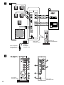
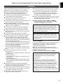
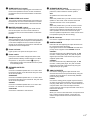
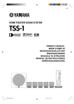
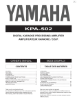
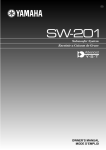
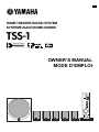
UCA
HOME THEATER SOUND SYSTEM
SYSTEME AUDIO HOME CINEMA
TSS-1
Active Servo
Technology
OWNER’S MANUAL
MODE D’EMPLOI
DIGITAL
INPUT
4CH
2CH
DTS
MODE
DIGITAL
TEST
PROLOGIC
MUTE
CENTER
SURROUND
SUBWOOFER
MASTER VOLUME
Active Servo
Technology
HOME THEATER SOUND SYSTEM
TSS-1
• Explanation of Graphical Symbols
CAUTION
The lightning flash with arrowhead
symbol, within an equilateral triangle,
is intended to alert you to the
presence of uninsulated “dangerous
voltage” within the product’s
enclosure that may be of sufficient
magnitude to constitute a risk of
electric shock to persons.
RISK OF ELECTRIC SHOCK
DO NOT OPEN
CAUTION: TO REDUCE THE RISK OF
ELECTRIC SHOCK, DO NOT REMOVE
COVER (OR BACK). NO USER-SERVICEABLE
PARTS INSIDE. REFER SERVICING TO
QUALIFIED SERVICE PERSONNEL.
The exclamation point within an
equilateral triangle is intended to alert
you to the presence of important
operating and maintenance
(servicing) instructions in the
literature accompanying the
appliance.
IMPORTANT
Please record the serial number of this system in the
space below.
Model:
Serial No.:
WARNING
TO REDUCE THE RISK OF FIRE OR ELECTRIC
SHOCK, DO NOT EXPOSE THIS APPLIANCE TO RAIN
OR MOISTURE.
The serial number is located on the rear of the main
unit.
Retain this Owner’s Manual in a safe place for future
reference.
SAFETY INSTRUCTIONS
1
Read these instructions.
2
Keep these instructions.
3
Heed all warnings.
4
Follow all instructions.
5
Do not use this apparatus near water.
6
Clean only with dry cloth.
7
Do not block any ventilation openings. Install in
accordance with the manufacturer’s instructions.
8
Do not install near any heat sources such as radiators,
heat registers, stoves, or other apparatus (including
amplifiers) that produce heat.
9
II
Do not defeat the safety purpose of the polarized or
grounding-type plug. A polarized plug has two blades
with one wider than the other. A grounding type plug
has two blades and a third grounding prong. The wide
blade or the third prong are provided for your safety. If
the provided plug does not fit into your outlet, consult
an electrician for replacement of the obsolete outlet.
10
Protect the power cord from being walked on or
pinched particularly at plugs, convenience receptacles,
and the point where they exit from the apparatus.
11
Only use attachments/accessories specified by the
manufacturer.
12
Use only with the cart, stand, tripod,
bracket, or table specified by the
manufacturer, or sold with the
apparatus. When a cart is used, use
caution when moving the cart/
apparatus combination to avoid injury
from tip-over.
13
Unplug this apparatus during lightning storms or when
unused for long periods of time.
14
Refer all servicing to qualified service personnel.
Servicing is required when the apparatus has been
damaged in any way, such as power-supply cord or
plug is damaged, liquid has been spilled or objects
have fallen into the apparatus, the apparatus has been
exposed to rain or moisture, does not operate normally,
or has been dropped.
1.
2.
3.
IMPORTANT NOTICE : DO NOT MODIFY THIS
UNIT!
This product, when installed as indicated in the
instructions contained in this manual, meets FCC
requirements. Modifications not expressly approved
by Yamaha may void your authority, granted by the
FCC, to use the product.
IMPORTANT : When connecting this product to
accessories and/or another product use only high
quality shielded cables. Cable/s supplied with this
product MUST be used. Follow all installation
instructions. Failure to follow instructions could void
your FCC authorization to use this product in the
USA.
NOTE : This product has been tested and found to
comply with the requirements listed in FCC
Regulations, Part 15 for Class “B” digital devices.
Compliance with these requirements provides a
reasonable level of assurance that your use of this
product in a residential environment will not result in
harmful interference with other electronic devices.
Compliance with FCC regulations does not guarantee that
interference will not occur in all installations. If this
product is found to be the source of interference, which
can be determined by turning the unit “OFF” and “ON”,
please try to eliminate the problem by using one of the
following measures:
This equipment generates/uses radio frequencies
and, if not installed and used according to the
instructions found in the users manual, may cause
interference harmful to the operation of other
electronic devices.
The above statements apply ONLY to those products
distributed by Yamaha Corporation of America or its
subsidiaries.
English
FCC INFORMATION (for US customers only)
Relocate either this product or the device that is being
affected by the interference.
Utilize power outlets that are on different branch (circuit
breaker or fuse) circuits or install AC line filter/s.
In the case of radio or TV interference, relocate/reorient
the antenna. If the antenna lead-in is 300 ohm ribbon
lead, change the lead-in to coaxial type cable.
If these corrective measures do not produce satisfactory
results, please contact the local retailer authorized to
distribute this type of product. If you can not locate the
appropriate retailer, please contact Yamaha Electronics
Corp., U.S.A. 6660 Orangethorpe Ave, Buena Park, CA
90620.
We Want You Listening For A Lifetime
YAMAHA and the Electronic Industries Association’s
Consumer Electronics Group want you to get the most out
of your equipment by playing it at a safe level. One that lets
the sound come through loud and clear without annoying
blaring or distortion – and, most importantly, without
affecting your sensitive hearing.
Since hearing damage from loud sounds is
often undetectable until it is too late, YAMAHA
and the Electronic Industries Association’s
Consumer Electronics Group recommend you
to avoid prolonged exposure from excessive
volume levels.
For Canadian Customers
To prevent electric shock, match wide blade of plug to
wide slot and fully insert.
This Class B digital apparatus complies with Canadian
ICES-003.
III
1
A
B
DIGITAL
INPUTS
OPTICAL
SPEAKER
OUTPUTS
L
FRONT
COAXIAL
R
L
SURROUND
R
ANALOG
INPUTS
1
FRONT
SURROUND
2
CENTER
S. WOOFER
SPEAKER
MODE
5CH
4CH
2CH
DIGITAL
INPUT
4CH
2CH
DTS
MODE
DIGITAL
TEST
PROLOGIC
MUTE
DC IN 15V
CENTER
SURROUND
SUBWOOFER
MASTER VOLUME
Rear panel
Panneau arrière
Technology
Amplifier unit
Unité d’amplification
PA-SR601:
AC adaptor
Adaptateur CA
To AC receptacle
Vers une prise du
réceptacle CA
2
Active Servo
HOME THEATER SOUND SYSTEM
TSS-1
See pages 6–7.
Voir page 6-7.
DIGITAL
INPUT
4CH
2CH
DTS
MODE
DIGITAL
TEST
PROLOGIC
MUTE
CENTER
1
2
3
4
5
DIGITAL
INPUTS
OPTICAL
SPEAKER
OUTPUTS
L
FRONT
B
E
L
SURROUND
R
6
SURROUND
COAXIAL
R
ANALOG
INPUTS
1
FRONT
SURROUND
F
2
7
SUBWOOFER
CENTER
S. WOOFER
MASTER VOLUME
Active Servo
Technology
Front panel
Panneau Avant
IV
HOME THEATER SOUND SYSTEM
TSS-1
8
C
9
0
A
D
SPEAKER
MODE
5CH
4CH
2CH
DC IN 15V
Rear panel
Panneau arrière
English
Thank you for selecting Yamaha TSS-1 Home Theater Sound System.
Cautions
Please read the following operating precautions before use.
YAMAHA will not be held responsible for any damage
and/or injury caused by not following the cautions below.
●
●
●
●
●
●
●
●
●
●
●
●
●
●
●
When you disconnect the AC adaptor from the AC
receptacle, hold the plug itself and not the cord.
If you plan not to use this system for a while, disconnect
the AC adaptor from the AC receptacle.
Always disconnect the AC adaptor from the AC
receptacle before making any connections.
This system does not contain any user serviceable parts.
Refer all servicing to your Yamaha dealer.
Never open the cabinet. If a foreign object drops into
the set, contact your dealer and stop using this system.
Otherwise, you may cause a fire.
Do not expose this system to extreme temperatures,
direct sunlight, excessive dust, humidity, or vibration.
Position this system on a level, stable surface. Do not
drop, apply excessive force to its controls, or put heavy
items on top of it.
Do not place small metallic objects on this system.
Otherwise, the object may fall, possibly causing an injury.
Since the amplifier unit has a built-in power amplifier,
heat will radiate from the ventilation slits. Place the
amplifier unit apart from the walls, allowing a space of at
least 20 cm (7-7/8”) above, 10 cm (3-15/16”) behind and
on both sides of the amplifier unit.
Also, do not position with the rear panel facing down on
the floor or other surfaces and do not cover the amplifier
unit with a newspaper, a tablecloth, a curtain, etc. in
order not to obstruct heat radiation.
If the temperature inside the amplifier unit rises, it may
cause fire, damage to the amplifier unit and/or personal
injury.
Do not place the following objects on this system:
Glass, china, etc.
If glass etc. falls by vibrations and breaks, it may cause
personal injury.
A burning candle etc.
If the candle falls by vibrations, it may cause fire and
personal injury.
A vessel with water in it
If the vessel falls by vibrations and water spills, it may
cause damage to this system, and/or you may get an
electric shock.
To protect this system, avoid microphone feedback,
continuous and excessive output from electronic musical
instruments, and excessive signal distortion.
If this system is located close to a monitor, or fluorescent
or neon lights, a slight hum may be heard. In this case,
relocate this system away from the light.
Although this system is magnetically shielded, keep
floppy disks and tapes away from it.
●
●
Avoid sources of hum (transformers, motors). To prevent
fire or electrical shock, do not expose to rain or water.
Do not use force on switches, knobs, or cables. When
you move this system, first turn off the power, then
disconnect the AC adaptor from the AC receptacle and
the cables from the connected devices.
Always set the MASTER VOLUME control fully to the left
before starting to play the audio source: turn the control
gradually after playback has started.
Be sure to only use the AC adaptor (PA-SR601)
supplied with this system. Otherwise, you might
cause a fire or damage to this system.
Standby mode
When this system is turned off by pressing the power
switch, this system consumes a small amount of power.
This state is called the standby mode. The power
supply is completely cut off from the AC line only when
the AC adaptor is disconnected.
This system features a magnetically shielded design, but
there is still a chance that placing it too close to a TV or
a computer monitor might impair picture color. Should
this happen, move this system away from the TV or the
computer monitor.
For U.K. customers
If the socket outlets in the home are not suitable for the plug
supplied with this appliance, it should be cut off and an
appropriate 3 pin plug fitted. For details, refer to the
instructions described below.
Note: The plug severed from the mains lead must be
destroyed, as a plug with bared flexible cord is hazardous if
engaged in a live socket outlet.
SPECIAL INSTRUCTIONS FOR U.K. MODEL
IMPORTANT:
THE WIRES IN MAINS LEAD ARE COLOURED IN
ACCORDANCE WITH THE FOLLOWING CODE:
Blue: NEUTRAL
Brown: LIVE
As the colours of the wires in the mains lead of this
apparatus may not correspond with the coloured
markings identifying the terminals in your plug, proceed
as follows: The wire which is coloured BLUE must be
connected to the terminal which is marked with the letter
N or coloured BLACK. The wire which is coloured
BROWN must be connected to the terminal which is
marked with the letter L or coloured RED. Making sure
that neither core is connected to the earth terminal of the
three pin plug.
E-1
Contents
SAFETY INSTRUCTIONS .............................. II
Controls & connectors ................................. 6
Cautions .......................................................... 1
Adjusting speaker balance ........................... 8
Unpacking ...................................................... 2
Playing a source ............................................ 8
Features ......................................................... 2
Troubleshooting ............................................ 9
Setting up the system ................................... 4
Specifications .............................................. 10
Connections .................................................. 6
Features
Unpacking
After unpacking, check that the following parts are included.
Multi-Channel Surround System for Home
Theater, Game Amusement and PC DVD.
● Amplifier unit
●
Combination of Amplifier Unit, Five Satellite
Speakers and Subwoofer
●
Dolby Digital and DTS decoder
●
5.1-Channel Full-Scale System for DVD Movie
Entertainment
●
5.1-Ch Full-Scale, 4.1-Ch (Game Surround)
and Stereo (Virtual Surround) Speaker Modes
●
Yamaha’s Exclusive Active Servo Technology
for Powerfull Bass Response
●
1 Optical and 1 Coaxial Digital Inputs
●
Two Analog Inputs (front/rear channel)
●
Test Tone Generator for Accurate Speaker
Balancing
● Satellite speaker x 5
●
●
Satellite speaker with a 3 m cord x 3
Satellite speaker with a 7 m cord x 2
● Subwoofer
● Accessories
●
●
●
●
●
●
●
●
E-2
AC adaptor (PA-SR601) x 1
Stereo mini plug cable x 2
Optical fiber cable x 1
RCA pin-plug cable x 1
Stand for the amplifier unit x 1
Screw x 2
Pad x 24
Fastener x 1
(Refer to the next page.)
English
Welcome to the exciting world of digital home entertainment.
The TSS-1 is a compact, but complete and advanced home theater sound system that takes you to the exciting world of digital
surround sound entertainment. Though some of the advanced features of this system may not be familiar to you, they are easy
to use. Incorporated state-of-the-art technology such as Dolby Digital and DTS can bring the same audio experience to your
home as they have brought to feature films in quality theaters around the world. Take some time now to read more about these
features and enjoy the new experiences this system brings to your home theater.
■ Dolby Surround
Dolby Surround uses four discrete channels and five
speakers to reproduce realistic and dynamic sound effects:
two main channels (left and right), a center channel for
dialog, and a rear channel for special sound effects. The
rear channel reproduces sound within a narrow frequency
range.
Most video tapes and laser discs include Dolby Surround
encoding, as do many TV and cable broadcasts. The Dolby
Pro Logic decoder built into this unit employs a digital signal
processing system that stabilizes each channel for even
more accurate sound positioning than is available with
standard analog processors.
■ Dolby Digital*
Dolby Digital is a digital surround sound system that
provides completely independent multi-channel audio to
you. Dolby Digital provides five full-range channels in what
is sometimes referred to as a “3/2” configuration: three front
channels (left, center and right), and two surround channels.
A sixth bass-only effect channel is also provided for output
of LFE (low frequency effect), or low bass effects that are
independent of other channels. (This is called the “LFE
channel”.) This channel is counted as 0.1, thus giving rise to
the term 5.1 channels in total.
The wide dynamic range of sound reproduced by the five
full-range channels and precise sound orientation by digital
sound processing provides listeners with excitement and
realism that have never been experienced before.
■ DTS (Digital Theater System) Digital
Surround**
DTS was developed to replace the analog soundtracks of
movies with six discrete channels of digital soundtracks,
and it is now installed in many theaters around the world.
The DTS digital playback system changed the way we
experienced movies in theaters with six discrete channels of
superb digital audio.
DTS technology, through intense research and
development, has made it possible to deliver similar
encode/decode discrete technology to home audio
surround-sound entertainment.
DTS Digital Surround is an encode/decode system which
delivers six channels of master-quality, 20-bit audio;
technically, it offers 5.1 channels, which means 5 full-range
(left, center, right and two surround) channels, plus a
subwoofer (LFE) channel (as “0.1”). It is compatible with the
5.1 speaker configurations that are currently available for
home theater systems.
Notes
● When playing an ordinary CD on this system following
playback of a CD or an LD encoded with DTS, some
operations, such as resetting input modes, may be required.
● Even if connected to this system with a digital connection,
some CD, LD, and DVD players may make this system fail to
decode DTS or produce noise. This is because certain digital
data processing by such players can result in DTS data
decoding errors that cause playback failure although the same
data processing may cause only a slight change in volume or
in frequency response with normal digital sound.
● If an error occurs in the player’s digital output data during
playback of an LD or CD encoded with DTS, playback may
be disrupted. If this occurs, stop playback and repower the
player.
● When digital sound signals from the computer are played,
errors in WAVE signals, etc. may occur resulting in noise or
playback failure.
*
Manufactured under license from Dolby Laboratories.
“Dolby”, “Pro Logic” and the double-D symbol are
trademarks of Dolby Laboratories. Confidential
Unpublished Works. q1992–1997 Dolby Laboratories,
Inc. All rights reserved.
**
Manufactured under license from Digital Theater
Systems, Inc. US Pat. No. 5,451,942 and other worldwide patents issued and pending. “DTS”, “DTS Digital
Surround”, are trademarks of Digital Theater Systems,
Inc. Copyright 1996 Digital Theater Systems, Inc. All
Rights Reserved.
E-3
Setting up the system
System configuration
Recommended speaker placement
This system includes an amplifier unit, five satellite
speakers and a subwoofer.
The three satellite speakers with a 3 m cord are used as
front speakers and a center speaker.
The two satellite speakers with a 7 m cord are used as
surround speakers.
Before making connections, place all speakers in their
respective positions. The positioning of the speakers is
important because it controls the overall sound quality of
this system.
Place the speakers depending on your listening position by
following the instructions below.
* The satellite speakers can be mounted on a wall. (See the
next page.)
The role of respective speakers
The front speakers are used for reproducing main channel
sound. The surround speakers are used for effect sounds,
and the center speaker is for center channel sound (dialog
etc.).
The subwoofer is used for reproducing sounds of low
frequencies from the front, center and surround channels.
The subwoofer also reproduces sounds of the subwoofer
channel when a DTS or Dolby Digital encoded source is
played.
Left front
speaker
Amplifier
unit
Subwoofer
E-4
Front speakers:
On both sides of and at approximately
the same height as the TV (or computer
monitor).
Surround speakers:
Behind your listening position or on
both sides of the listening room.
Center speaker:
Precisely between the front speakers.
* The center speaker can be mounted
on the monitor as shown on the next
page.
Subwoofer:
On the floor. The position of the
subwoofer is not so critical because low
bass tones are not highly directional.
Right front
speaker
Center
speaker
Left
surround
speaker
Right
surround
speaker
English
m Adjusting the front angle of the satellite
speakers
m Placing a center speaker on top of the
monitor
The front angle of the satellite speakers can be adjusted as
shown below.
When placing the center speaker on top of the monitor,
remove the stand from the speaker, and attach the provided
fastener at the bottom of the speaker and on top of the
monitor to prevent the speaker from falling.
* Do not place the speaker on top of the monitor with an
inclination of more than 10 degrees.
1
Loosen the screw on the bottom of the speaker stand.
* Attach the supplied nonskid pads at the four corners
on the bottom of the stand for improved stability.
10&
10&
Fastener
Pads
2
Adjust the speaker angle on the stand as you prefer, and
then tighten the screw.
Note
m Mounting satellite speakers on a wall
The satellite speakers can also be hung on the wall.
Fasten screws into a firm wall or wall support as shown in
the figure, and hang the slits on the rear of the speaker on
the protruding screws.
* Make sure that the screws are securely caught by the
slits.
Tapping screw (4 mm)
(Available in hardware stores)
4 mm
Though this speaker is a magnetically shielded type, there
may be some influence on the monitor picture depending on
the type of monitor or the placement of the speaker. In such a
case, place the speaker further apart from the monitor until
there is no influence on the monitor picture.
m Mounting the amplifier unit on the supplied
stand
For improved stability, it is recommended to mount the
amplifier unit on the supplied stand with the supplied screws
as shown below.
* Attach the supplied nonskid pads at the four corners on
the bottom of the stand for improved stability.
Min.
20 mm
Wall/ wall
support
50 mm
To front
Pads
Warning
● Each speaker weighs 0.4 kg (0.9 lbs.). Do not mount them
on thin plywood or a wall with soft surface material. If
mounted, the screws may come out of the flimsy surface
and the speakers may fall. This could damage the speakers
and cause personal injury.
● Do not install the speakers on a wall with nails, adhesives,
or any other unstable hardware. Long-term use and
vibrations may cause them to fall.
● To avoid accidents resulting from tripping over loose
speaker cords, fix them to the wall.
E-5
Connections
(See figure 1 on page IV.)
Caution: Plug in the amplifier unit and other
equipment after all connections are
completed.
A : Connect the three satellite speakers with a 3 m cord to
the FRONT L, R and CENTER terminals. Connect the
two satellite speakers with a 7 m cord to the
SURROUND L and R terminals. Connect the
subwoofer to the SUBWOOFER terminal.
B : Connect external audio/video units (a personal
computer, a video game player, a portable DVD/CD
player, a video cassette player, etc. which send
playback signals to this system) to these terminals.
Cautions
● When placing the provided AC adaptor on the desk, etc.,
be sure to fix the adaptor on the desk, etc. to prevent it
from falling. If the adaptor falls, it may cause personal
injury or damage to the adaptor and/or other equipment.
● The SPEAKER OUTPUT terminals on the rear of the
amplifier unit are only designed for connection of the
supplied speakers. Never connect these terminals to an AV
amplifier or a power amplifier, as it may cause
misoperation, fire and/or damage to this system.
Controls & connectors
(See figure 2 on page IV.)
1
INPUT selector button and indicators
DIGITAL:
Select this mode to reproduce a Dolby Digital encoded
input source.
This mode can be selected only when the input signal
is encoded with Dolby Digital and the input mode is set
to DIGITAL.
Press this button repeatedly to select an input mode
between DIGITAL, 4CH and 2CH. The current mode is
shown by the lighting of the corresponding indicator.
DIGITAL:
Select this mode to reproduce signals received at the
OPTICAL or the COAXIAL terminal on the rear panel.
When both OPTICAL and COAXIAL terminals receive
signals, the signals at the OPTICAL terminal are
selected.
4CH:
Select this mode to reproduce signals received at the
analog input FRONT and SURROUND terminals on
the rear panel in 4-channel surround sound mode. (The
center speaker is not used in this mode.)
PROLOGIC:
Select this mode to reproduce a Dolby Prologic
encoded input source.
This mode cannot be selected when the input mode is
set to 4CH.
3
Press this button to reproduce a test tone from the
speakers. A test tone is reproduced from each speaker
as shown below. The test tone is used for adjusting
volume balance among all the speakers.
2CH:
Select this mode to reproduce signals received at the
analog input FRONT terminal on the rear panel. (The
PROLOGIC surround mode can be used in this
mode.)
2
DTS:
Select this mode to reproduce a DTS encoded input
source.
This mode can be selected only when the input signal
is encoded with DTS and the input mode is set to
DIGITAL.
E-6
FRONT L
CENTER
SURROUND L
FRONT R
SURROUND R
* Not all of the speakers reproduce the test tone
depending on the setting of the SPEAKER MODE
switch (C).
MODE selector button and indicators
Press this button repeatedly to select the desired
DIGITAL,
surround mode between on (DTS,
PROLOGIC) and off. The current mode is shown by
the lighting of the corresponding indicator.
* If a DTS or Dolby Digital encoded signal is inputted
when the surround mode is off, the corresponding
indicator lights up dimly.
TEST button
4
MUTE button and indicator
Press this button to cut off sound output temporarily.
When this function is active, the indicator lights up.
Press this button again to restore sound output.
* Sound output will also be restored by changing the
status of this system between standby and power-on
modes, and changing the input mode or the surround
mode.
5
CENTER level control
This control is used for adjusting the sound level from
the center speaker. Turn this control clockwise to
increase the level, and counterclockwise to decrease
the level.
SURROUND level control
C
This control is used for adjusting the sound level from
the surround speakers. Turn this control clockwise to
increase the level, and counterclockwise to decrease
the level.
7
5CH:
All speakers are used in this mode.
4CH:
Select this position when you will not use the center
speaker. In this mode, center sound is mixed and
outputted from the front L and R speakers.
SUBWOOFER level control
2CH:
Select this position when you will not use the center
and surround speakers. In this mode, sounds of all
channels are mixed and reproduced from the front L
and R speakers as virtual surround sounds. [The
surround speakers reproduce the same sounds as the
front speakers (except for the test tone).]
MASTER VOLUME control
This control is used for adjusting the overall volume
level of this system. Turn this control clockwise to
increase the level, and counterclockwise to decrease
the level.
9
Headphone jack
Stereo headphones can be connected to this mini-jack
for private listening. Sound output from the speakers is
cut off when headphones are connected to this jack.
Sounds of all channels are mixed into 2 channels and
reproduced over the headphones.
0
D
E
Power indicator
OPTICAL:
Connect an external unit (a DVD/CD player, an MD
recorder, a video game player, etc.) with an optical
digital output terminal to this terminal by using the
supplied optical cable.
Power switch
COAXIAL:
Connect an external unit (a DVD/CD player, an MD
recorder, a video game player, etc.) with a coaxial
digital output terminal to this terminal by using the
supplied RCA pin-plug cable.
SPEAKER OUTPUTS
FRONT:
Connect one satellite speaker with a 3 m cord to the L
terminal and another to the R terminal. They are used
as the front speakers.
SURROUND:
Connect one satellite speaker with a 7 m cord to the L
terminal and the other to the R terminal. They are used
as the surround speakers.
CENTER:
Connect one satellite speaker with a 3 m cord to this
terminal. It is used as the center speaker.
S. WOOFER:
Connect the subwoofer to this terminal.
DIGITAL INPUTS
External units with digital signal output terminals can
be connected to these terminals.
Input signals received at the OPTICAL terminal have
priority over the signals at the COAXIAL terminal.
Each press of this switch changes the status of this
system between standby mode and power on. When
the power is on, the power indicator (0) lights up.
* Note that this system uses a small amount of power
in the standby mode.
B
DC IN connector
Connect the supplied AC adaptor to this connector.
Lights up when the power of this system is on.
A
SPEAKER MODE switch
Normally, set this switch to 5CH. According to your
preference, set this switch to another position.
This control is used for adjusting the sound level from
the subwoofer. Turn this control clockwise to increase
the level, and counterclockwise to decrease the level.
8
English
6
F
ANALOG INPUTS
Connect the analog signal output terminals of an
external unit to these mini-jack terminals by using the
supplied mini plug cables or commercially available
pin-to-mini plug cables.
FRONT:
Connect the analog (stereo) signal output terminal of
an external unit to this terminal by using the supplied
mini plug cable. When you connect a sound board on a
computer which has 4-channel output terminals,
connect the front channel output terminal of the sound
board to this terminal.
SURROUND:
When you connect a sound board on a computer which
has 4-channel output terminals, connect the rear
channel output terminal of the sound board to this
terminal.
E-7
Adjusting speaker balance
Notes
●
This procedure lets you adjust the sound output level
balance between the front, center and surround speakers
by using the built-in test tone generator. Make this
adjustment so that each speaker output level is about the
same when heard at the listening position. This is important
for high performance of the built-in DTS decoder and Dolby
Digital decoder.
* Once you have completed this adjustment, you can
adjust the overall volume level of this system by using
only the MASTER VOLUME control.
When the SPEAKER MODE switch is set to “4CH”:
The test tone for the center channel is reproduced from both
the left and right front speakers at the same time.
When the SPEAKER MODE switch is set to “2CH”:
The test tones for the left and right surrounnd channels are
reproduced from the left and right front speakers
respectively. The output order of the test tones is as follows.
FRONT L
VIRTUAL SURROUND L
FRONT R
VIRTUAL SURROUND R
DIGITAL
INPUT
DIGITAL
INPUTS
OPTICAL
4CH
2CH
DTS
SPEAKER
OUTPUTS
MODE
DIGITAL
●
TEST
PROLOGIC
MUTE
5, 8
COAXIAL
FRONT
Adjust the subwoofer level while listening to playback sounds
of a source.
L
R
L
CENTER
SURROUND
4, 7
ANALOG
INPUTS
R
1
SURROUND
Playing a source
FRONT
SURROUND
2
CENTER
SUBWOOFER
S. WOOFER
2, 6
1
SPEAKER
MODE
5CH
4CH
2CH
This section explains how to turn on this system and select
input sources. Before turning on this system, turn on the
external audio unit to be used.
MASTER VOLUME
DC IN 15V
Active Servo
Technology
HOME THEATER SOUND SYSTEM
TSS-1
3
DIGITAL
INPUT
4CH
2CH
DTS
MODE
DIGITAL
TEST
PROLOGIC
3
6
MUTE
1
Set the SPEAKER MODE switch to “5CH”.
2
Turn the MASTER VOLUME control fully counterclockwise to decrease the volume to minimum.
SURROUND
3
Turn on this system.
4
Set the CENTER and SURROUND level controls at
the center position.
1, 5
5
Press the TEST button.
6
Adjust the master volume to the desired level.
* You will hear a test tone (so called pink noise) from each
speaker for about two seconds in the following order.
FRONT L
CENTER
SURROUND L
8
E-8
SUBWOOFER
MASTER VOLUME
Active Servo
Technology
HOME THEATER SOUND SYSTEM
TSS-1
2
SURROUND
CENTER
7
CENTER
FRONT R
SURROUND R
Adjust the CENTER and SURROUND level controls
while listening to the test tones so that their levels
become about the same as the front speakers’
level.
* Adjust the right-left volume balance of the front speakers
and the surround speakers by changing the position of
each speaker.
When the adjustment is completed, press the TEST
button.
* The test tone stops .
1
Turn the MASTER VOLUME control fully
counterclockwise to decrease the volume to
minimum.
2
Turn on this system.
3
Select the appropriate input mode by pressing the
INPUT selector button.
* The indicator for the selected input mode lights up.
* Refer to the “Controls & connectors” on page 6 for
details about the input modes.
4
Play a source on the external unit.
5
Adjust the volume to the desired level.
6
Select a desired surround mode.
* Refer to the “Controls & connectors” on page 6 for
details about the surround modes.
Refer to the chart below if this system does not function properly. If the problem you are experiencing is not listed below or if
the instructions given below do not help, disconnect the AC adaptor and contact your authorized YAMAHA dealer or service
center.
Problem
Cause
What to Do
The AC adaptor is not properly plugged into
the AC receptacle.
Insert the AC adaptor firmly into the AC
receptacle.
The power of the amplifier unit is set in the
standby mode.
Turn on the power by pressing the power
switch. (The power indicator lights up.)
Connections are faulty or incomplete.
Make the connections again.
The appropriate input mode is not selected.
Select the appropriate input mode by
pressing the INPUT selector button.
The volume setting is low.
Turn the MASTER VOLUME control
clockwise to increase the volume.
The MUTE function is active. (The indicator
on the left side of the MUTE button is lit.)
Press the MUTE button to cancel this
function.
The SURROUND level control is set to
minimum.
Turn the SURROUND level control clockwise
to increase the level.
The surround mode is off.
Select the appropriate surround mode by
pressing the MODE button. If no mode can
be selected, change the input source to
another which is encoded with DTS, Dolby
Digital or Dolby Prologic.
The CENTER level control is set to minimum.
Turn the CENTER level control clockwise to
increase the level.
The SPEAKER MODE switch on the rear
panel of the amplifier unit is set to “2CH” or
“4CH”.
Set the SPEAKER MODE switch to “5CH”.
The surround mode is off.
Select the appropriate surround mode by
pressing the MODE button. If no mode can
be selected, change the input source to
another which is encoded with DTS, Dolby
Digital or Dolby Prologic.
No sound from the center and
surround speakers though the DTS or
DIGITAL mode indicator is dimly
illuminated.
Dim illumination of an indicator means that
signals encoded with the corresponding
format (DTS or Dolby Digital) is inputted to
this system. In this case, the signals are
mixed into 2 channels and reproduced from
the front speakers only.
Press the MODE button for the appropriate
surround format. The indicator turns bright,
and the center and surround speakers
reproduce sounds since the surround format
is decoded.
Though a Dolby Digital encoded
source is inputted to this system, the
DIGITAL mode indicator is dimly
illuminated and the
PROLOGIC
mode indicator is brightly illuminated.
A Dolby Digital 2-channel encoded source is
inputted to this system.
If the input source is compatible with 5.1
channels, select “5.1-channel mode” on the
player which is sending signals to this
system. (If the input source is not compatible
with 5.1 channels, you can enjoy the source
in a multi-channel mode by using the
PROLOGIC surround mode.)
Sound is distorted.
The level of the input signal is too high.
Turn down the output level on the connected
component.
Noise.
The level of the input signal is too low.
Turn up the output level on the connected
component.
Connections are faulty or incomplete.
Make the connections again.
The amplifier unit is too close to the monitor.
Place the amplifier unit away from the
monitor.
No sound from the speakers or
subwoofer.
No sound from the surround speakers
No sound from the center speaker
English
Troubleshooting
E-9
Specifications
Amplifier unit
Output Power per Channel
..................................... Satellite: 6W (1 kHz, 4Ω, 10% THD)
Subwoofer: 18W (100 Hz, 4Ω, 10% THD)
Input Sensitivity ..................................................... 200 mV
Subwoofer
Type ................ Active Servo Processing Subwoofer System
Driver ............................................... 13 cm (5”) cone woofer
Magnetically shielded type
Headphone Jack Output Level/Output Impedance
............................................. 450 mV/30Ω (1 kHz, 200 mV)
Impedance ...................................................................... 4Ω
Frequency Response ................................... 40 Hz–20 kHz
Dimensions (W x H x D) ....... 220 mm x 224 mm x 222 mm
(8-11/16” 2 8-13/16” 2 8-3/4”)
Dimensions (W 2 H 2 D) .............. 113 2 272 2 206 mm
(4-7/16” 2 10-11/16” 2 8-1/8”)
Weight ......................................................... 3.4 kg (7.5 lbs.)
Weight ......................................................... 1.5 kg (3.3 lbs.)
Accessories
Satellite speakers
Type ............................................ Full range speaker system
Magnetically shielded type
Driver ......................................... 5 cm (2”) spruce cone type
Impedance ...................................................................... 4Ω
AC adaptor (PA-SR601) 2 1
Stereo mini plug cable (1.8m) 2 2
Optical fiber cable (1.0m) 2 1
RCA pin-plug cable (1.8m) 2 1
Stand for the amplifier unit 2 1
Screw 2 2
Pad 2 24
Fastener 2 1
Dimensions (W x H x D) ........ 70 mm 2 95 mm 2 118 mm
(2-3/4” 2 3-3/4” 2 4-5/8”)
Weight ......................................................... 0.4 kg (0.9 lbs.)
E-10
* Please note that all specifications are subject to change
without notice.
YAMAHA
YAMAHA
YAMAHA
YAMAHA
YAMAHA
YAMAHA
YAMAHA
ELECTRONICS CORPORATION, USA 6660 ORANGETHORPE AVE., BUENA PARK, CALIF. 90620, U.S.A.
CANADA MUSIC LTD. 135 MILNER AVE., SCARBOROUGH, ONTARIO M1S 3R1, CANADA
ELECTRONIK EUROPA G.m.b.H. SIEMENSSTR, 22-34, 25462 RELLINGEN, BEI HAMBURG, F.R. OF GERMANY
ELECTRONIQUE FRANCE S.A. RUE AMBROISE CROIZAT BP70 CROISSY-BEAUBOURG 77312 MARNE-LA-VALLEE CEDEX02, FRANCE
ELECTRONICS (UK) LTD. YAMAHA HOUSE, 200 RICKMANSWORTH ROAD WATFORD, HERTS WD1 7JS, ENGLAND
SCANDINAVIA A.B. J A WETTERGRENS GATA 1, BOX 30053, 400 43 VASTRA FRÖLUNDA, SWEDEN
MUSIC AUSTRALIA PTY, LTD. 17-33 MARKET ST., SOUTH MELBOURNE, 3205 VIC., AUSTRALIA
Printed in Malaysia
V729330