1
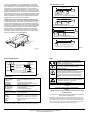
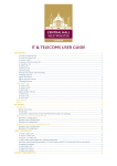
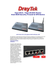
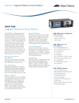
Installation
NTE8E Engineer’s Installation Guide
British Telecommunications plc 2004
www.bt.com/isdn
The ISDN2e Network Terminating Equipment NTE8E is manufactured by
Introduction
•
•
•
•
The NTE8 is the customer termination for the BT ISDN2e service and this
document is a guide to the installation procedure.
This unit is a direct replacement for the NTE8A, B, C and D.
It must not be used as a replacement for an NTE6.
This NTE has the addition of a copper by-pass feature that enables a
no-customer visit to change service to PSTN or Broadband and will take
the place of an NTE5.
This unit can also be used on low voltage ISDN lines.
Unit Description
Enhanced
Status LED
Network cable entry
NTE
SW2 L / S
ATTENTION! – Default Configuration
Check the IN/OUT and L/S switches are both in the
default position of “IN” and “S” unless providing
Customer Extension Wiring.
PSTN
Connector
Access to removable cover
BT Engineer only
SW1
IN / OUT
ISDN Terminal Equipment
1
Document Number: 8820
1. Wall mounting
The NTE8 can be mounted in most domestic and office environments, avoiding
direct sunlight, sources of heat, sources of electromagnetic radiation, and areas
which are subject to high humidity such as kitchens and laundry rooms etc.
The NTE must be mounted with the customer sockets facing down.
Use the template provided with this guide to mark the two fixing screw positions.
Please note that a minimum of 190mm clearance is required (marked by dashed
lines) to enable the customer to insert and remove the extension cabling or
terminal equipment plugs into the RJ45 sockets and to enable the installation
engineer to open and remove the cover.
CAUTION: Before drilling holes, make sure that there are no concealed
installations (e.g. power, water, gas).
Drill (∅ 6 mm) and plug the wall for the two crosshead screws provided. For a hollow wall, suitable
proprietary fixing should be used. If fitting to wood,
drill suitable pilot holes.
Position the screw that will mate with the keyhole
fixing, leaving approx 2mm protruding (see fig. 2a)
to allow a snug fit in the slot and the NTE lies flat
against the mounting surface without any case
distortion.
Hang the NTE over the screw head and pull it
Figure 2a
down until it locks in place safely (see fig. 2b).
Then insert the second screw in the lower hole.
Ensure that the case fixings are sound and that
there is no movement, but do not over-tighten the
securing screws.
Figure 2b
Figure 1
2
11. October 2004
ATTENTION! Dangerous Voltage!
The ISDN connection is a voltage source that should be inaccessible to the
user. The NTE cover shall only be opened by BT ISDN trained engineers. Do
not touch the PCB unless you are wearing an anti-static strap. The strap is not
required for normal line installation. Do not install the NTE or work on the line
during thunderstorms.
3. Lightning Protection
Lightning protection shall be provided as for standard PSTN lines. Where the
service is provided via aerial cable either over more than three spans, or in
areas with a high risk of electric storms, the circuit may require additional
protection. Please refer to the Lightning Protection Handbook
ISIS/EPT/PPS/B055.
2. Connecting the NTE8 to the Network
Remove the BT Engineer-only-removable cover to gain access to the network
wiring connectors. This cover is attached to the lower part of the NTE with a clip.
To loosen the locking mechanism use a No.1 screwdriver and push it slightly
into the rectangular slot above the switch marked “OUT” (see Unit Description).
Strip approximately 100mm of sheath from the network cable, feed the cable
into the NTE and route the cable through the chicane. (see fig. 3). Terminate the
cable on the IDC, wiring polarity is unimportant. Replace the network access
cover.
4. Customer S-Bus Extension Wiring (Chargeable Option)
Cable to category 5 specification should be used to complete the installation.
Please refer to the table below for RJ45 wiring and Figure 5 for sample wiring
configurations / switch settings. All extension wiring MUST have a Type 2 socket
(which incorporates terminating resistors), as the last socket.
Further wiring details can be found in BS EN 50098-1.
SW3 for
Bypass function
(see chapter 6),
default setting:
Plug & Play
Network cable
IDC connector
ISDN
Plug&Play
Network cable
Tension relief
Figure 3
Write the customer directory and fault reporting number on the customer service
label.
Pin
1
2
3
4
5
6
7
8
Wire colour
White/orange
Orange/white
White/green
Blue/white
White/blue
Green/white
White/brown
Brown/white
TE
P Source 3
P Source 3
Transmit
Receive
Receive
Transmit
P Sink 2
P Sink 2
NT
P Sink 3
P Sink 3
Receive
Transmit
Transmit
Receive
P Source 2
P Source 2
5. Testing and fault locating
A green LED in the centre indicates the status of the NTE.
OFF
ON (dim)
Flashing quickly
(8 Hz)
Flashing slowly
(1 Hz)
ON (bright)
LED Indicator
No Service or device in bypass mode
Exchange line Voltage > 30V
but line side deactivated, no layer 1
Network connection activating
Normal Service (layer 1) with No Customer Terminal Equipment
(CPE) connected or detected. Network connection active but
customer side S-Bus deactivated (or activating).
Normal Service (layer 1) with CPE connected and detected.
3
4
Hinweis für die Herstellung: Papier unterhalb dieser Linie abschneiden!
Note: Cut off paper below this line!
If the LED is ON (bright) then voice and data testing should be completed by
using an ISDN Basic Access Tester, Digital CPE Simulator, laptop or similar
device. Use the tester to confirm “Power Source 1 restricted”. A brightly lit state
will confirm layer 1 activated but not the presence of a TEI. On System X exchanges a double slow flash may be observed every 15 seconds, this is caused
by the line card toggling between Info State 2 and 0. This is typical of all embedded System X lines when there is no CPE connected or CPE is detected but not
in the correct Info State. The LED not lit or permanently fast flashing indicates a
problem with the network connection. A permanently slowly flashing LED could
indicate a problem with the customer wiring or CPE. BT Engineers Assistance
Website - http://customerservice.intra.bt.com/eassistant/
6. NTE Bypass function for PSTN and Broadband mode (Extended Use)
The NTE will detect the line voltage from the exchange and switch automatically
to the ISDN or PSTN mode. The NTE will provide PSTN service to the PSTN
socket if a standard analogue line card is used and will act as an NTE5. When
the ISDN service is jumpered/enabled in the Local Exchange, the NTE supports
ISDN services and the PSTN socket is disconnected. The NTE will switch back
to the analogue PSTN mode if the ISDN service is removed/de-configured.
The NTE will switch out of copper bypass at 75 ±8 volts and switch back into
copper by-pass when the voltage falls below 30 ±3 volts. An internal switch
SW3 (position: see fig. 3) is provided so the installer can over ride the by-pass
feature to allow operation on low voltage ISDN lines.
7. Example S-BUS Connections
Short passive bus
150m max.
S/T
NTE 8
< 1m max.
TE1
TE2
TE8
Switch IN/OUT to OUT and L/S to S
Last socket (TE1) must include termination resistors
Daisychained
150m max.
S/T
TE1
NTE 8
TE2
TE8
Switch IN/OUT to OUT and L/S to S
Last socket (TE1) must include termination resistors
Extended Passive Bus
500 m ... 800 m
25 m ... 50 m
S/T
NTE 8
<1m
TE
1
TE
2
TE
4
Switch IN/OUT to OUT and L/S to L
Last socket (TE1) must include termination resistors
Point-to-Point
150 m ... 800 m
Network cable entry
S/T
NTE 8
Analogue & ADSL
Equipment
TE1
Switch IN/OUT to OUT and L/S to L
Socket (TE1) must include termination resistors
Figure 5
Figure 4
5
6
Functional Block Diagram
Safety
By-Pass
Detection
This equipment complies with the European directives
89/336/EEC “Electromagnetic Compatibility” (EMC) and
73/23/EEC “Low Voltage Directive”.
Do not work on the NTE and its wiring, e.g. connect or disconnect cables, during periods of lightning activity.
RJ45
RJ45
Exch
ISDN- signal
switching unit
1µ8
2µ2
PSTN
470k
470k
PSTN / ADSL Broadband By-Pass
Figure 6
Technical Data
U interface
TS 102 080, Annex A
Channel structure
2B+D, synchronization and service data
Line code
2B1Q
Net data rate
144 kbps (2 x 64 kbps + 16 kbps)
Safety status
TNV3 (Telecommunication Network Voltage)
S/T interface
according to ETS 300 012
Channel structure
2B+D, synchronization and monitoring
Bus configuration:
S = Short passive bus
(default setting)
IN = 50Ω Terminating Resistors
Safety status
TNV1 (Telecommunication Network Voltage)
Power
ITU-T I.430
Wattage on S/T interface < 420 mW in operation
Dimensions and environmental conditions
Storage
ETS 300 019-1-1, Class 1.1 (-25°C to +55°C)
Transport
ETS 300 019-1-2, Class 2.3 (-25°C to +55°C)
Operation
ETS 300 019-1-3, Class 3.2 (-5°C to +55°C)
Case
123 x 130 x 50 mm
Weight
0.5 kg
Our products are subject to continuous further development and improvement.
7
Hazardous Voltages !
Remote Power Feeding / ISDN connection (Line)
The ISDN connection is regarded as a source of voltage that
should be inaccessible to user contact. Do not attempt to
tamper with or open the NT1 or the connection hardware.
Maintenance must be made only by suitably trained engineers.
ESD Protection (for service personnel)
When handling the unit with the cover opened, please use
ESD protection methods acc. to EN 100 015.
Not required for normal installation.
All customer ordered facilities must be tested prior to handover to
customer.
This guide should be retained for future reference.
Returns
If the NTE is proved to be faulty on installation, please return it using the
BT return procedure.
If you have any comments to make about this documentation, or the ISDN NTE
please email: [email protected].
The information contained in this guide is correct at the time of going to press, but it is not
comprehensive and shall not form any part of a contract. Some products and services may
not be available in all areas. Whilst we do our best to supply customers with the products
and services that they ask for, we reserve the right to supply products and services which
do not accord exactly with the descriptions and illustrations in this guide.
Hinweis für die Herstellung: Papier unterhalb dieser Linie abschneiden!
Note: Cut off paper below this line!
8