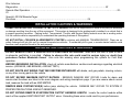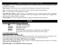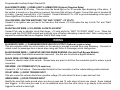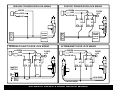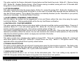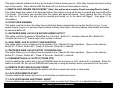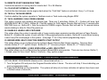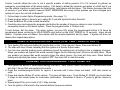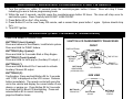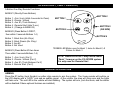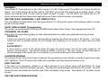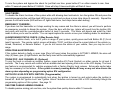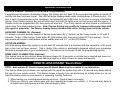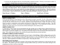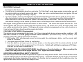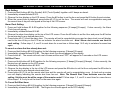
1
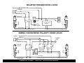
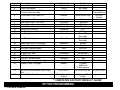
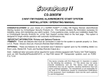
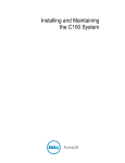
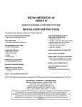
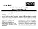
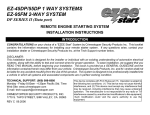
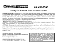
CS-2013FM
2-Way FM Remote Start & Alarm System
CONGRATULATIONS! on your choice of a CS-2013FM 2-Way FM Paging Remote Alarm/Remote Starting System
by Crimestopper Security Products Inc. This booklet contains the information necessary for installing, using, and
maintaining your alarm system. If any questions arise, contact your installation dealer first, or Crimestopper
Security Products Inc. at the Tech Support number listed below. This system is designed for single vehicle
operation. The Remote start functions of this system are designed for use with automatic equipped transmission,
fuel injected vehicles only. This system is compatible with diesel engines.
*IMPORTANT INFORMATION: Primary and Optional Features
-PRIMARY: These are features that must be connected in order for the system to operate properly i.e. Siren,
L.E.D., Power, Ground, Door pin, Hood pin (Remote Start Inhibit) etc.
-OPTIONAL: These are features to be connected only if desired or agreed upon by the installing dealer (i.e. Door
Locks, Starter Disable, Trunk, and Auxiliary Remote Output etc.)
Note: Additional labor and parts will be required for some features and on vehicles equipped with Factory AntiTheft Systems such as GM PassKey®/Passlock®/VATS, or Key-FOB based RF Transponder systems such as
FORD P.A.T.S.®
TECHNICAL SUPPORT (800)-998-6880
Monday - Friday 8:00am - 4:30pm Pacific Standard Time
Website: www.crimestopper.com
E-mail: [email protected]
CRIMESTOPPER SECURITY PRODUCTS, INC.
1770 S. TAPO STREET, SIMI VALLEY, CA. 93063
This device complies with FCC Rules part 15. Operation is subject
to the following two conditions: (1) This device may not cause
harmful interference, and (2) This device must accept any
interference that may be received, including interference that may
cause undesired operation. The manufacturer is not responsible
for any radio or TV interference caused by unauthorized
modifications to this equipment. Such modification could void the
user’s authority to use the equipment.
TABLE OF CONTENTS
Installation Cautions & Warnings…….………….…………………………...………………………………………………2-3
Suggested Component
Mounting………….……...……………………………...…………………………….……………....3
Wiring Information……………………………….……………………………..……………………………...………….…….47
Power Door Lock Wiring...………………………..…………………………………….……………………………..….……89
Remote Start: Tach & Tach-less Programming……………………………………..……………………………….……1011
Option Programming……………………………….…………….………………………...………………….…………….1115
Option Reset
Procedure…………………………..…………..…………………………………………………………….…..15
Custom “Personal” Override
Code………………..………………..…………………………………………………...……..16
Remote Sensor Adjust
Mode…………………………..……..…………………………………...……………………..…….16
One Way Transmitter
Programming.……..……………………………………….……………………………………..…….16
Two-Way Transceiver
Programming…………………….…..………………….…………………..………………...………17
Remote Control Diagrams…………………….…………………………………………………..……………..………....1718
Alarm Operation………………………………..………….…………………………………………..………………..…...1821
Remote-Less Protection “Beach
Mode”……………………………………………………………………...…………..……21
Prior Intrusion
Diagnostics………………………….………………………………………………………...……….…..……22
Remote Start Operation……………….…………………………………………………………………………..….……..2223
Special LCD FM Remote-Pager
Functions……….…………………………………………………………..………………24
INSTALLATION CAUTIONS & WARNINGS
CRIMESTOPPER SECURITY PRODUCTS, INC. and its VENDOR shall not be responsible or liable in any way for accidents
or damage resulting from the use of this equipment. This system is designed to be professionally installed in a vehicle that is
in proper operating condition. Parking brake, Transmission, Throttle, and Engine Safety features must be in working order.
It is the vehicle owner’s responsibility to understand the operating features of this system.
DO NOT INSTALL CS2005FM ALARM/REMOTE STARTER in vehicles with MANUAL TRANSMISSIONS! There are no
safety features built into this unit for manual transmission vehicles. If accidentally left in gear, a remote started vehicle could
become a self-propelled threat to life and property.
INSTALLATION CAUTIONS & WARNINGS
DO NOT REMOTE START A VEHICLE IN A CLOSED AREA OR GARAGE! Make sure that door is open or there
is adequate ventilation is provided. Failure to observe this rule could result in serious injury or death from
poisonous Carbon Monoxide fumes! Also note this warning when programming this system for Cold Start
operation.
BEFORE BEGINNING INSTALLATION, check all vehicle manufacturer cautions and warnings regarding electrical
service. (AIR BAGS, ABS BRAKES, AND BATTERY).
DO NOT ROUTE ANY WIRING THAT MAY BECOME ENTANGLED with brake, and gas pedals, steering column,
or any other moving parts in the vehicle.
DO NOT EXCEED MAXIMUM OUTPUT RATINGS - SERIOUS DAMAGE MAY OCCUR. Limits for alarm and
remote start functions are listed in the main diagram and wiring descriptions page. If you are unsure about current
load, measure the load with an AMP-METER.
REMOVE MAIN SYSTEM FUSE(S) before jump starting the vehicle. DAMAGE MAY OCCUR TO SYSTEM IF
PROPER PRECAUTIONS ARE NOT OBSERVED.
DO NOT EXTEND REMOTE START/IGNITION OUTPUT HARNESS LENGTH. Locate the control module within
reach of the supplied IGNITION/START OUTPUT wires. Extending these wires could result in poor performance.
SUGGESTED COMPONENT MOUNTING
Control Module: Driver or Passenger side underdash, the unit should be placed as high as possible, not easily
accessible by an intruder.
Shock Sensor: Mount with wire ties to an under dash wire harness or fasten with screws to a panel.
Siren: Under the hood to fender-well or other body surface with the open end facing downward.
LED: In a visible location on the dashboard or console.
Override/Program button: Hidden location, but accessible to the user in case the system must be disarmed
without the use of the transmitter. This switch is also used to program certain features and to page/call the
transceiver from inside the vehicle if necessary.
Antenna Module: Inside front windshield (as high as possible) using supplied double sided tape.
WIRING
6 PIN HI-CURRENT REMOTE START CONNECTOR:
RED:
+12V INPUT (30 Amp Fused)
RED:
+12V INPUT (30 Amp Fused)
YELLOW:
IGNITION 1 (Primary) Output
ORANGE:
ACCESSORY Output
PURPLE:
STARTER Output
BROWN:
Multi Function Output (IGNITION #2 / ACCESSORY #2 / STARTER #2)
(Programmable, See option table #23. Default set for IGN 2 output)
20 PIN MAIN HARNESS PLUG:
GREEN/WHITE WIRE: +12V BRAKE INPUT
Connect this wire to the side of the brake pedal switch that shows +12V only when the brake is depressed. This
input is used to reset remote start after entering the running vehicle and turning the ignition key on.
BLACK/GRAY WIRE: TACH SIGNAL INPUT (Used For Tach Mode)
Used to monitor Tach Pulses when the engine is running. Connect to negative terminal of ignition coil, crankshaft
position sensor or ECM/PCM tach wire.
WHITE/RED WIRE: (-) AUX. REMOTE OUTPUT #2 (Optional)
Programmable Auxiliary Output Channel #2.
BLACK/WHITE WIRE: (-) DOME LIGHT ILLUMINATION (Optional, Requires Relay)
Connect to terminal 85 of relay. This wire turns the dome light on for 30 seconds upon disarming of the alarm. If
the ignition is turned on or the alarm is re-armed, the dome light will turn off again. Connect this wire to terminal 85
of a relay. Connect terminal 86 to +12V Constant. Connect terminal 87 to +12V or ground depending on the type of
Dome Light/Door Pin circuit that is in the vehicle.
YELLOW WIRE: IGNITION SWITCHED “ON” AND “START” +12 VOLTS
Connect to an ignition wire (or fuse in the fuse box) that shows +12 Volts when the key in both “On” and “Start”
positions.
BLUE/YELLOW WIRE: (+12V) DIESEL GLOW PLUG INPUT
Connect Pink wire to indicator circuit that shows +12 volts while the “WAIT TO START LAMP” is on. When this
wire is used, the CS-2013FM unit will wait until light turns off before attempting a remote start. Note: a relay may be
required for vehicles that have a Negative Wait to Start lamp circuit.
WIRING
BLUE/WHITE WIRE: (-) PASSENGER DOOR UNLOCK OUTPUT (Optional, requires relay)
This wire activates when the unlock button on the remote is pressed a second time upon disarming. Connects to
unlock circuit for passenger door or doors when using split Driver & Passenger unlock configuration.
BLUE/ORANGE WIRE: (-) NEGATIVE GROUND WHEN RUNNING (For Anti-Theft Bypass Module)
Sends a constant Ground with remote start command. Use this wire to activate a Bypass Modules.
BLACK WIRE: SYSTEM CHASSIS GROUND
Connect to chassis metal of the vehicle. Scrape away any paint or dirt from the connection point to ensure a good
connection.
RED WIRE: +12V POWER INPUT (15 amp fuse)
Connect to +12 Volt source. Recommended location for this connection is at the vehicle battery positive terminal.
VIOLET WIRE: (+) DOOR TRIGGER INPUT
This wire is used for vehicles that show a positive voltage (12 volts) when the door is open such as Ford.
GREEN WIRE: (-) DOOR TRIGGER INPUT
Identify the wire that reads ground when any door is open and 12 volts when all doors are closed. Some isolated
door triggers. In this case you need to run an additional wires from the other doors or go directly to the wire that
triggers the vehicle’s dome light.
WHITE/BLACK WIRE: (-) HOOD/TRUNK TRIGGER (Mandatory For Hood Pin)
Input trigger for a grounding hood or trunk pin switch and to inhibit remote start if the hood is open. Connect to
existing hood and trunk pin switches that read ground when open. If no existing switches are available, install a
new pin switch. Note: DO NOT mount new pin switches in water pathways.
ORANGE WIRE: (-) NEGATIVE ARMED OUTPUT (STARTER DISABLE)
Sends constant Ground output when system is armed. This output is used for adding a starter disable relay. For
starter kill, cut starter wire and connect between 87A and 30 on relay. Connect orange wire to 85 and connect 86 to
Ignition Source that has voltage in the ON and CRANKING position. Be sure to connect the Purple Remote Starter
Cranking output to the Motor side of the Starter Disable Relay or it will not allow the Remote Starter to operate.
VIOLET/WHITE WIRE: (-) OEM FACTORY DISARM OUTPUT
Provides a ground pulse to DISARM the vehicle’s FACTORY anti-theft system prior to Remote Start. Connect this
wire to the vehicles' anti-theft disarm wire. This wire may be found coming off the Driver's door key switch or the
Factory Anti-theft control module.
WIRING
WHITE/VIOLET WIRE: (-) OEM FACTORY ARM OUTPUT
Provides a ground pulse to ARM the vehicles' FACTORY after Remote Start. Connect this wire to the vehicle’s antitheft Arm wire.
BROWN WIRE: (+) SIREN OUTPUT (3 amp max.)
Connect to RED siren wire.
GRAY WIRE: (-) AUX. REMOTE OUTPUT #1 (Trunk Pop)
Provides Negative Pulse output for Factory Electronic Trunk Release. Requires relay for Positive type circuits.
WHITE WIRE: +12V FLASHING PARKING LIGHT OUTPUT
Connect to switched parking light wire at back of light switch. If this is not possible, connect directly to one of the
parking lights at the front of the vehicle. European may vehicles require separate right and left circuits. Use a dual
relay or 2 diodes to separate the output signal.
BROWN/WHITE WIRE: (-) HORN HONK or (-) NEGATIVE IGNITION OUTPUT (Optional, Programmable)
Negative pulsed output for Horn Honk. Can also be programmed for an additional negative run output (Option #24).
2 PIN (BLUE) PLUG: PROGRAM / OVERRIDE BUTTON
2 PIN (RED) PLUG: LED INDICATOR (Red Flashing Light)
3 PIN DOORLOCK (WHITE) PLUG:
GREEN:
RED:
BLUE:
9.
(-) NEGATIVE LOCK
+12V For Relays
(-) NEGATIVE UNLOCK
Connect directly to negative lock/unlock systems. If vehicle uses
positive door lock signals or reversing polarity type, then external
relays must be added. See Power Door Lock Wiring: Pages 8-
4 PIN (WHITE) SENSOR PLUG:
WHITE:
NEGATIVE PRE-WARN
BLACK: SENSOR GROUND
BLUE:
NEGATIVE TRIGGER
RED:
SENSOR POWER
3 PIN (BLUE) DATA PLUG ON RIGHT SIDE OF MODULE: Data port for 2-WAY FM Transceiver Box &
Antenna
4 PIN (WHITE) DATA PLUG ON RIGHT SIDE OF MODULE: Port for optional extended range antenna for 1way remote control.
WIRING TABLE
20 PIN CONNECTOR (18 GA. WIRES)
PIN #
1
2
3
4
5
6
7
8
9
10
11
COLOR
GREEN/WHITE
BLACK/GRAY
WHITE/RED
BLACK/WHITE
YELLOW
BLUE/YELLOW
BLUE/WHITE
BLUE/ORANGE
BLACK
RED
VIOLET
DESCRIPTION
(+) 12 BRAKE LIGHT INPUT
TACH SIGNAL INPUT (ENGINE RPM0
(-) AUXILIARY CHANNEL OUTPUT #2
(-) DOME LIGHT SUPERVISION OUTPUT
(+) 12V IGNITION SWITCH INPUT
(+) 12V GLOW PLUG INPUT
(-) NEGATIVE PASSENGER UNLOCK OUTPUT
(-) NEGATIVE IGN. OUTPUT (GROUND WHEN
RUNNING)
(-) CHASSIS GROUND
(+) 12 POWER INPUT
(+) POSITIVE DOOR TRIGGER INPUT
12
13
14
15
16
17
18
GREEN
WHITE/BLACK
ORANGE
VIOLET/WHITE
WHITE/VIOLET
BROWN
GRAY
19
20
WHITE
BROWN/WHITE
(-) NEGATIVE DOOR TRIGGER INPUT
(-) HOOD/TRUNK TRIGGER INPUT
(-) ARMED OUTPUT (STARTER DISABLE)
(-) OEM FACTORY DISARM OUTPUT
(-) OEM FACTORY ARM OUTPUT
(+) SIREN POSITIVE OUTPUT
(-) NEG AUXILIARY CHANNEL OUTPUT #1 (TRUNK
POP)
(+) 12V PARKING LIGHT OUTPUT
(-) NEG HORN HONK OR NEG IGN OUTPUT
POWER DOOR LOCK WIRING
NEGATIVE TRIGGER DOORLOCK WIRING
POSITIVE TRIGGER DOORLOCK WIRING
GREEN
GREEN
RED
RED
BLUE
BLUE
FUSED
+12V
+
85
86
87
87A 30
FACTORY
POWER
LOCKING
RELAYS
L
UL
REVERSE POLARITY DOOR LOCK WIRING
GREEN
FUSED
+12V
+
RED
BLUE
85
86
87
87A 30
85
86
87
87A 30
85
86
87
87A 30
FACTORY
POWER
LOCKING
L
UL
RELAYS
AFTERMARKET DOOR LOCK WIRING
GREEN
FUSED
+12V
+
RED
BLUE
85
86
87
87A 30
85
86
87
87A 30
MASTER
SWITCH
+
L
UL
CUT
LOCK WIRE
CUT
UNLOCK WIRE
SEPARATE DRIVER’S DOOR UNLOCK WIRING
NEGATIVE TRIGGER DOOR LOCKS
BLUE/WHITE
GREEN
RED
BLUE
DRIVER'S
DOOR MOTOR
85
86
87
30 87A
L
L
UL
UL
FACTORY LOCK
RELAYS
+12V
+
FUSED
UNLOCK WIRE
CUT
WIRING FOR REVERSE POLARITY DOOR LOCKS
BLUE/WHITE
GREEN
RED
FUSED
+12V
+
BLUE
MASTER
SWITCH
85
85
86
87
30 87A
86
87
87A 30
+
L
86
87
87A 30
CUT
UL
CUT
85
CUT
LOCK WIRE
UNLOCK WIRE
REMOTE START:TACH & TACHLESS MODE
The CS2013FM system includes both Tach and Tach-less modes for engine sensing & starter control. This system
can be programmed for either mode, but it is set to Default in “Tachless Mode”. It will work for most vehicles in
Tach-less mode.
SMART SENSE TACH-LESS MODE:
When the system is in “Smart Sense” Tachless mode, the module monitors the vehicle’s voltage, and RF noise level
reference each time a remote start is performed. No Tach wire is required when using “Smart Sense” Tach-less
mode. The Smart Tachless system works from the existing +12V power connections of the unit. DO NOT USE
THE BLACK/GRAY TACH WIRE WHEN IN TACHLESS MODE!
TACH (RPM MONITOR) MODE:
Tach Mode provides reliable remote starting performance though engine speed sensing. When using Tach Mode,
the BLACK/GRAY wire is used for Tach signal [Engine RPM] input. Most modern engines include various points
where the Engine Speed [Tach] or A/C signal may be obtained. Tach Signal examples: Negative (-) side of ignition
coil, at the Distributor or Ignition Control Module, Coil Pack, Engine Computer, or Crankshaft Sensor. Sometimes
Fuel injection solenoids, and Alternator stator pins can be used. These Tach Signal locations mentioned are
provided as a guide, your vehicle may differ. Some locations will NOT be a good location for Tach source due to
RF noise or Computer Data.
**IMPORTANT - TACH MODE IS A 2-PART PROCESS!!**
The CS-2013FM unit must be set up for Tach mode because it is set for Tach-less mode by Default. PART 1 is to
go into the programming option #20 and set the unit for Tach mode. Once the unit is set for Tach mode (RPM
monitor), you must learn the Tach Signal of the Vehicle in a second set of steps. Carefully read BOTH sets of steps
to become familiar with these options before programming the unit.
SET THE CS-2013FM FOR TACH MODE:
1. Turn Ignition ON and within 10 seconds press the valet/program button 5 times. The siren should chirp 3
times.
2. Within the next 5 seconds press the override/program button [again] 20 times. The siren will chirp once for
each button press. Press carefully and DO NOT lose count. Option #20 is for “Tach or “Tach-less” mode.
3. Press the #2 Unlock Button on remote transmitter. The unit will now be set for Tach Mode (RPM Monitor).
4. If lights do not flash twice for confirmation, then try another tach source or try the tach finder.
*SEE NEXT PAGE FOR TACH (Engine RPM Signal) LEARING STEPS.*
TACH (RPM SIGNAL) LEARNING
LEARNING THE TACH (RPM) SIGNAL:
1. Have the Black/Gray Tach wire connected to your Tach source.
2. Start engine with key.
3. Within 10 seconds, press the valet/program button 5 times, the siren should chirp 3 times.
4. Push program button again (21) times, you should get a siren chirp for each button press. Be careful and DO
NOT LOSE COUNT. This unit is now at option #21-Tach Learning.
5. Press the #1 Lock Button on remote transmitter. The unit will record and program your Tach source.
NOTE (1): The Tach Signal locations suggested on page10 are provided as a guide, your vehicle may differ.
Some locations will NOT be a good location for Tach source due to RF noise or Computer Data. The CS2013FM may not detect a clean signal. If you are unable to locate a Tach Source, use the “Smart Sense
Tachless” mode.
NOTE (2) The CS2013FM is in “Smart Sense Tachless” Mode [by default]
OPTION PROGRAMMING STEPS (USE 1-WAY REMOTE ONLY!)
**IMPORTANT NOTE: When programming options, you can ONLY USE THE ONE-WAY REMOTE**
Follow steps below to access Programming Options:
1. Turn the ignition on, within 10 seconds press the override/program button 5 times. Siren should chirp 3 times
2. Within the next 5 seconds press the override/program button [again] the number of times that corresponds to the
listed feature below. The siren will chirp once for each button press.
3. Once you are at the desired option number, press Button #1, 2 or 3 on the ONE WAY remote to change the
option. Button #1 gives one light flash/chirp and Button #2 give two flashes/chirps, Button #3 gives three
flashes/chirps.
4. Turn OFF Ignition when finished changing an option. Change ONE option at a time and repeat steps 1 thru 3.
**SEE OPTIONS TABLE ON PAGE**
OPTION PROGRAMMABLE OPTIONS TABLE
Option # Option Description
BUTTON #1
BUTTON #2
BUTTON #3
1.
2.
3.
4.
5.
Passive Arming
Active Re-Arm
Silent Arm/Disarm
Lock when IGN turns ON/
Custom Override mode
Unlock when IGN turns OFF
6.
7.
8.
9.
10.
11.
12.
Double Unlock Pulse
Door Lock Pulse: 1 or 3 sec.
Passive Lock
Beach Mode (Remote-less Disarm)
Open Zone Warning
Aux #2 output actives when armed
Aux #1 output type
13.
Aux #2 output type
14.
15.
16.
17.
18.
19.
20.
21.
22.
Disarm with Aux #1 Activation
Remote Start while in VALET
Lock Upon Remote Start
Lock Upon Engine Shutdown
Engine Run Time
Cold Start Feature
Tach or Tachless mode
Tach Programming/Engine Type
Enable 2-Way FM pager
23.
BROWN (Multi Remote Start Output
Wire
Brown/White Wire Function
24.
Disabled*
Disabled*
Chirps*
Enabled*
Enable
Enable
No Chirps
Disabled
Enabled*
Driver’s door only
1 Pulse*
1 Second*
Disabled*
Disabled*
5 Seconds*
Disabled*
Pulsed*
IGNITION 2*
2 Pulses
3 Seconds
Enable
Enable
OFF
Enable
Timed (10
Seconds)
Timed (10
Seconds)
Enable
Enable
No Lock
No Lock
12 Minutes*
Every 1 Hour*
Tach
Gas Engine
Program
Additional
2-Way pagers
ACCESSORY #2
Pulsed Horn Honk
Output*
Negative IGN
output
Pulsed*
Disabled*
Disabled*
Lock*
Lock*
24 Minutes
Every 2 Hours
Tachless*
Learn Tach*
Enable*
Custom
Override Mode
NO IGN
Unlock
Latched
Latched
Diesel Engine
STARTER #2
* = INDICATES FACTORY DEFAULT VALUE
OPTION PROGRAMMING
1. PASSIVE ARMING
This option controls the Passive (Automatic) Arming feature and the Hands free mode. Button #1 = Passive Arming
OFF. Button #2 = Enables Passive Arming. When Passive arming is enabled, arming will occur 30 Seconds after
the ignition is turned off and the last door has been closed.
2. ACTIVE RE-ARMING
This option controls the Active Re-arming feature. Button #1 = Active Re-arming OFF. Button #2 = Enables Active
Re-arming. Active Re-arming allows the system to re-arm itself 30 seconds after disarmed with the transmitter if a
door has not been opened. This is handy if the vehicle is accidentally disarmed (via the Transmitter in your pocket)
without your knowledge. (Accidental Disarm Protection)
3. SILENT ARMING / DISARMING (CHIRP DEFEAT)
With this feature, the system can be programmed to Arm and Disarm without the siren chirp using the regular
Lock/Unlock Buttons. Flashing parking lights will be the only Arm/Disarm confirmation.
4. IGNITION-LOCK / CUSTOM OVERRIDE
This option controls whether the door locks when Ignition is turned on and the custom override feature. There are 3
selections: Button #1 = Lock with vehicle Ignition ON. Button #2 = Do Not Lock with ignition. Button 3 (Trunk)=
Custom override programming mode. (See custom override section on Page 16)
The custom override feature allows the user to set a “personalized” override code. If the system has to be manually
disarmed (overridden) without the remote, the user can customize the number of button presses (2-15x) to do this
other than the default operation, which is a single press and hold of the button.
5. IGNITION-UNLOCKING
This option controls door unlocking when Ignition is turned OFF. There are 3 selections: Button #1 = Unlock all
doors when Ignition is turned OFF. Button #2 = Unlock Drivers door only*. Button 3 = NO Ignition Unlock. *Only
applicable when using optional Driver’s priority unlock feature.
6. DOUBLE UNLOCK PULSE
The option controls whether the unit will send 2 unlock pulses when the Unlock button is pressed. This feature may
be required for interfacing this alarm with an existing Factory Keyless Entry or Alarm system in a vehicle. These
systems are found on some Nissan, VW, Toyota, and Lexus vehicles.
7. DOOR LOCK PULSE TIME
Controls the amount of time (1 sec. or 3 sec.) for the lock/unlock pulse. The 3 sec. setting is only required for
1980’/90’s European Vehicles that require a long pulse to do Vacuum door lock systems.
OPTION PROGRAMMING
8. PASSIVE LOCKS
This option controls whether the doors will lock when Passive Arming occurs. Note: May increase the risk of locking
keys in the vehicle. When selected ON, the alarm will lock the doors when passive arming.
9. REMOTE-LESS DISARM “BEACH MODE” (Note: this option also requires Passive arming/Passive locks)
This option allows the system to be disarmed without the remote as long as the key is inserted and turned ON within
10 seconds. This feature only operates after the system has passively armed. Upon opening the door, the siren
will chirp for 10 seconds, the key must be inserted and turned on, or the alarm will trigger. (See page 21 for
information.)
10. DOOR OPEN WARNING
This option controls the door the delay time in which the alarm system begins to monitor the Door circuit. If your
system begins to give you warning chirps because of delay dome light or courtesy lighting, then disable this option
by selection Button #2.
11. WHITE/RED WIRE: AUX #2 OR SECOND ARMED OUTPUT
This option controls the system’s White/Red Aux. #2 output. Button #1 = Auxiliary Channel #2 or Button #2 =
Constant Ground a a 2nd armed output when system is armed.
12. GRAY WIRE: AUX #1 OUTPUT CONFIGURATION
This option allows you to configure how the system’s Aux. Channel #1 output operates. There are two choices:
Button #1 = Pulsed. Button #2 = Timed-10 Seconds. Button #3 = Latched
13. WHITE/RED WIRE: AUX #2 OUTPUT CONFIGURATION
This option allows you to configure how the system’s Aux. Channel #2 output operates. There are two choices:
Button #1 = Pulsed. Button #2 = Timed-10 Seconds. Button #3 = Latched
14. DISARM WITH AUX. #1 OUTPUT (TRUNK POP)
Controls whether the system will or will not DISARM when the trunk pop or AUX. channel #1 is activated. When the
feature is turned ON, the unit will DISARM with trunk-pop or using an auxiliary device connected to the Gray wire.
15. REMOTE START WHILE IN VALET MODE
Allows to user to determine whether the system will allow a remote start when in Valet mode.
16. LOCK UPON REMOTE START
Controls whether the system will Lock or not lock when a remote start occurs.
17. LOCK UPON ENGINE SHUTDOWN / ABORT
Controls whether the system will Lock or not lock when a remote start “times out” or is aborted by the user.
OPTION PROGRAMMING
18. REMOTE START ENGINE RUN TIME:
Controls the amount of running time for remote start: 12 or 24 Minutes.
19. COLD START INTERVAL TIME
Controls the time between remote engine starts when the “Cold Start” feature is activated: Every 1 or 2 hours.
20. TACH or TACHLESS MODE
Controls whether the system operates in Tachless mode or Tach mode using Engine RPM.
21. TACH LEARNING / GAS / DIESEL ENGINE
This option controls tach learning and engine type. There are 3 selections: Button #1 = System will learn tach
(ENGINE MUST BE AT IDLE). Button #2 = Set the system for GAS engine: Remote Start will occur 3 seconds after
IGNITION turns on. Button #3 = Sets the system for DIESEL engine: Remote Start will wait for 10 seconds before
remote starting to allow for Glow Plug warm-up.
22. ENABLE & LEARN 2-WAY FM PAGER
This option allows the system to operate with a 2-way remote pager expansion module and learn a Pager Remote.
Button #1 = Enables the system to work with the 2-Way paging expansion module. Button #2 is used when learning
a new 2-way FM remote/pager to the system. (See page 17 for 2-Way remote programming steps)
23. BROWN WIRE: MULTI-FUNCTION REMOTE START OUTPUT
This option allows you to configure how the system’s Brown Remote Start Output operates. There are three
choices: Button #1 = 2nd Ignition Output. Button #2 = 2nd Accessory Output. Button #3 = 2nd Starter Output
24. BROWN/WHITE WIRE: (-) NEG HORN HONK or NEG. IGN OUTPUT
This option allows you to configure how the system’s Brown/White wire operates. There are two choices: Button 1)
= Pulsed output for Horn Honk. Button 2 (Unlock) = Neg. Ignition output.
OPTION RESET PROCEDURE PROGRAMMING
OPTION RESET PROCEDURE (Restores ALL Values listed with an *):
1. Turn the Ignition ON and press the Program/Override button 5 times. The siren will chirp 3 times indicating you
are in programming mode.
2. Press the #3 Button on the Transmitter. The system will chirp (6) six times indication all options have been reset
to Default values (Column #1).
CUSTOM “PERSONAL” OVERRIDE CODE
Custom override allows the user to set a specific number of button presses (2 to 15) required to perform an
emergency override/disarm of the alarm system. This helps to defeat the common perception of a thief that if you
turn the vehicle’s ignition on and press the valet button, most alarms will shut down. This feature increases the level
of security of your alarm system, however MUST MEMORIZE how many button presses you have changed your
system to use or the unit will not disarm!!!
1.
2.
3.
4.
Follow steps to enter Option Programming mode. (See page 11)
Press program button 4 times to go to option #4 “Lock with Ignition/Custom Override”.
Press the Button #3 on the remote transmitter.
Carefully press and release the program/valet button the number of times you desire in order to perform
emergency disarm on this alarm system. Press the program button 2-15 times only.
To test feature: Set the alarm. Trip alarm system, turn key ON, press the program/valet button 2-15 times as
programmed above continuing to HOLD DOWN valet button on the LAST PRESS for 10 seconds. Alarm should
disarm. If system does not disarm, then disarm with the remote transmitter and try again. If system still does not
disarm, then repeat steps above.
REMOTE SENSOR ADJUST MODE (USE 1-WAY REMOTE ONLY!)
1. Turn Ignition ON and press button #5 (side button) on the 1-Way remote 3 times, then press Button #3.
2. The siren will chirp 4 times indicating that the system is in Sensor Adjust mode.
3. You can now carefully produce some vibrations around the vehicle such as kicking a tire or slapping a bumper.
When you produce an impact that would normally trigger the Pre-Warning level, the siren will chirp twice. When
you produce an impact that would normally trigger the shock sensor, the siren will chirp once. When finished
testing and adjusting the sensor, turn Ignition OFF, then back ON to clear this mode.
TRANSMITTER PROGRAMMING: 1-WAY REMOTES
1. Turn ignition on and off 3 times within leaving it on the 3rd time. (on/off, on/off, on) Wait for 3 seconds and siren
will chirp 3 times if this was performed correctly.
2. Press the override/program button for approx. 5 seconds until 5 siren chirps are heard. LED also comes on
solid.
3. Press and release Button #1 on the remote. The siren will chirp once. Press Button #1 AGAIN, you should hear
2 chirps on the second press for code-learn confirmation. Sometimes it takes a 3rd press to get the remote to
learn.
4. Repeat step #3 for up to a total of (4) 1-Way remotes.
5. Turn the ignition off and wait a few seconds before trying new remotes.
ADDITIONAL TRANSCEIVER PROGRAMMING: 2-WAY FM REMOTE
1. Turn the ignition on, within 10 seconds press the override/program button 5 times. Siren will chirp 3 times
indicating you are in feature programming mode.
2. Within the next 5 seconds, carefully press the override/program button 22 times. The siren will chirp once for
each button press. Press Carefully and DO NOT LOSE COUNT.
3. Press Button #2 on the 1-Way remote.
4. Press Button #1 on the new 2-way FM remote, wait a second then press button 1 again. System should chirp
2x’s.
5. Turn OFF Ignition.
OPERATION: (2-WAY FM REMOTE TRANSCEIVER)
2-WAY FM REMOTE OPERATION:
BUTTON #1 (Lock Symbol):
Press and release to Arm/Disarm, Lock/Unlock system.
Press and Hold for PANIC feature.
BUTTON #2 (Key Symbol):
Press and Hold for 2 seconds Start or Stop Engine
BUTTON #3 (Trunk Symbol):
Press and Hold for trunk pop or (Auxiliary #1 output.)
BUTTON #4 (*):
Press and Hold Button #4 for 2 seconds to activate
Auxiliary Channel #2 output.
BUTTON #5 (C):
Confirmation: Press and hold Button #5 for 3 seconds
until “CON” is displayed on the LCD screen. Release
button immediately. The remote control will query the
unit in the vehicle and display the current status of arm,
disarm, or engine run. Press Button #5 for 2 seconds
to activate the EL Blue LCD backlighting. Press and
release Button #5 to cancel incoming
page/confirmation tones.
5-BUTTON LCD PAGER/REMOTE TRANSCEIVER
FRONT
FIXED ANTENNA
BUTTON #2
REMOTE
START
BUTTON #1
ARM/DISARM
(LOCK/UNLOCK)
TIME OF DAY
REMOTE
BATTERY LIFE
LCD SCREEN
SIDE VIEW
BUTTON #3
TRUNK POP
BUTTON #4
AUX #2
BUTTON #5
CONFIRM
STATUS
OPERATION: (1-WAY REMOTE)
5-Button One-Way Remote Functions:
BANK #1 (Directly Press Buttons)
Button 1:
Button 2:
Button 3:
Button 4:
Button 5:
Arm / Lock (Hold 4 seconds for Panic)
Disarm / Unlock
Aux #1 (Trunk Release)
Remote Start (Hold 2 sec.)
(Change to BANK #2)
BUTTON 2
BUTTON 1
BUTTON 3
PANIC
BUTTON 5
(ON SIDE)
BANK #2 (Press Button 5 FIRST,
then within 3 seconds Buttons 1-4)
BUTTON 4
Button 1: Silent Arm (No Chirp)
Button 2: Silent Disarm (No Chirp)
Button 3: Aux #2
Button 4: Not Used
BANK #3 (Press Button #5 two times
Then within 3 seconds Buttons 1-4)
Button 1: Arm / Lock (Car 2)
Button 2: Disarm / Unlock (Car 2)
Button 3: Aux #1 (Trunk Release Car 2)
Button 4: Remote Start (Car 2)
*GREEN LED Blinks once for Bank 1, twice for Bank 2, &
3 times for Bank 3
NOTE: Button #4 on the 1-Way remote reads
“Panic”, however on the CS-2013FM system
it is only used for Remote Start.
ALARM OPERATION
ARMING:
Press the #1 button (Lock Symbol) on either style remote to arm the system. The 2-way remote will confirm on
the LCD display with a “LOCK” icon and an audible signal. At the vehicle, the siren will chirp once and the lights
will flash once. The red LED in the vehicle will start flashing. The system will arm, (lock the doors, and the starter
will be disabled if these optional features are installed).
ALARM OPERATION
DISARMING:
Press Button #1 (Lock Symbol) on the 2-Way remote. For the 1-Way remote Press Button #2 (Unlock Symbol) to
disarm. The 2-Way remote will confirm with an “UNLOCK” icon on the LCD display and an audible signal. At the
vehicle, the siren will chirp (2) times and the lights will flash (2) times. The red LED in the vehicle will turn off.
(Doors will unlock and the interior dome light will turn on if these optional features are installed.)
ONE-TIME SILENT ARM/DISARM: (1-WAY REMOTE ONLY)
Press the Button #5 (Side button) first, then press Button #1 or #2 and the system will arm/disarm without a chirps
just on a one-time basis.
SILENT ARM & DISARM: (Programmable)
The system can programmed to ARM and DISARM silently without Siren Chirps. See programming Option #3.
TRIGGERING THE ALARM:
After a short 15 second Arming delay (to allow vehicle/electronics to settle), the system becomes fully armed.
INTRUSION:
If there is an intrusion at the vehicle (door/hood/trunk opening) the alarm will sound for 45 seconds. The 2-way
remote will emit an audible melody, the LCD Display will a flashing icon to inform you which zone has been
violated.
SHOCK/IMPACT:
A hard impact or shock to the vehicle body will trigger the shock sensor and trip the alarm system for 20
seconds. as listed above. The LCD will display a hammer / crash icon. This may or may not mean that there is
actually damage on the vehicle, but it is a reminder to you that a harder impact was detected.
ALARM PRE-WARNING:
If a low-level shock to the vehicle body is detected, the pre-warning sensor activates sounding 5 quick siren chirps
and 1 light flash. The LCD remote will confirm with an audible warning and a small hammer icon.
PANIC FEATURE:
In the event of an emergency situation or to attract attention to your vehicle, press and hold Button #1 (Lock
Symbol) on either remote for at least 4 seconds. The Siren will sound and lights will flash for 40 seconds. The LCD
remote will emit and audible alert and the word “PAN” will display on the screen. Press Button #1 on either remote
to reset.
ONE-TIME SHOCK SENSOR BYPASS:
To arm the system and bypass the shock for just that one time, press button #1 on either remote to arm, then
within 10 seconds press Button #1 AGAIN. Siren will chirp 5 times and lights will flash 5 times.
ALARM OPERATION
VALET MODE:
To disable the Alarm functions of the system while still allowing door lock/unlock, turn the ignition ON and press the
override/program button until the dash LED turns on solid and you hear a siren chirp (about 5 seconds). Repeat the
process to exit valet mode (LED will turn off, lights flash twice, and chirps twice when exiting).
EMERGENCY OVERRIDE:
If you have lost the transmitter or it stops working for any reason and the Alarm is armed, you will have to perform
an emergency override to disarm the system. Open the door with the key, (alarm will sound) turn the Ignition ON,
and press and hold the override/program button at least 5 seconds. The Alarm will disarm and enter the Valet
mode to allow you to use the vehicle. You can repair/replace the remote or see your installing dealer for assistance.
ALARM RANGE/STATUS CHECK: (2-Way Remote Only)
To perform a status check, or to test if you’re in range of your system, quickly press and hold Button #5 (C) for at
least 2 seconds. The remote control screen will display “CON”, and then show the current status of the vehicle i.e.
Armed, Disarmed, or Remote Started. If you do not receive the status of your vehicle, then you may be out of
range.
OPEN ZONE ALERT/BYPASS:
If the system detects a faulty or open zone (Door left open) when the system is ACTIVELY ARMED, the siren will
chirp (4) times, give (4) light flashes, and the faulty zone will be automatically bypassed.
TRUNK POP - AUX CHANNEL #1: (Optional)
To pop the trunk or activate an auxiliary feature, press button #3 (Trunk Symbol) on either remote for at least 2
seconds. The 2-way remote will confirm with an audible alert and opening trunk icon on the LCD display. The trunk
pop feature is recommended for vehicles equipped with a Factory Electric trunk release. Extra parts and/or labor
may be necessary for this feature. If the system is armed, pressing Button #3 may or may not also disarm the
alarm system depending on programming option #14 configuration.
AUTOLOCK & UNLOCK WITH IGNITION: (Programmable)
The system is programmed to automatically lock when the ignition is turned on and unlock when the ignition is
turned off. Both the “Ignition Lock” and “Ignition Unlock” features can be turned ON or OFF individually through the
programming options of this system. See page 12.
ONE-TIME PASSIVE ARMING DISABLE:
To disable passive arming just one time, arm the system then quickly disarm within 10 seconds.
ALARM OPERATION
PASSIVE ARMING / PASSIVE LOCK MODES: (Programmable)
If programmed for passive (Automatic) Arming, the system will Arm itself 30 Seconds after the ignition is turned off
and the last door has been closed. The LED will begin flashing rapidly while counting down to Passively Arm. If a
door is open or reopened during the countdown, the system will wait (LED solid) for the door or zone to close before
arming. Upon Passive arming, the unit will chirp once and flash the lights once just like arming with the remote. If
Passive Locks are programmed ON, then doors will also lock. The 2-Way remote will also receive a confirmation
signal when the system passively arms. Note: Passive Arming may qualify for insurance discounts-check with
your agent or proprietor. The Passive locking feature increases the risk of locking keys inside the vehicle.
AUXILIARY CHANNEL #2: (Optional)
To activate a second auxiliary feature or device press button #4 (* Symbol) on the 2-way remote for at least 2
seconds. On the 1-Way remote, Press button #5 (Side button) first, then press button #3 (Trunk symbol). The 2way remote will provide a confirmation with an audible alert and “0-1” on the LCD display.
ACTIVE RE-ARMING:
Active Re-arming allows the system to re-arm itself 30 seconds after it is disarmed with the transmitter in the event
that a door has not been opened. This is handy if the vehicle is accidentally disarmed without your knowledge
(Remote is pressed while in your pocket/purse). This feature can be turned off with the programming options.
DOME LIGHT ILLUMINATION: (Optional)
This feature turns on the vehicle’s dome light upon disarm for 30 seconds or until the key is inserted and turned on.
This will provide illuminated entry to your vehicle at night or in dimly lit areas for safety and security.
REMOTE-LESS DISARM “Beach Mode”
NOTE: Both options #1-Passive Arming and #9-Beach Mode must be enabled to use this feature.
This feature allows you to disarm your system with the use of the Ignition Key and a 10 second entry delay without
the use of a your remote control. This feature comes in handy if you are performing an activity where you do not
want the remote control on your person i.e. swimming, boating, beach etc.
1. When leaving your vehicle passive arming will occur. (Keys in hand, no remote)
2. When you return to your vehicle open your door manually and enter your vehicle. A 10 second entry delay is
activated upon door opening and the siren will begin to chirp.
3. Insert key into the Ignition and turn to the ON position to disarm the alarm. If the key is not turned on within 10
second (i.e. Intruder) then your system will go into a full alarm trigger.
PRIOR INTRUSION DIAGNOSTICS (ONE-WAY REMOTE ONLY)
This system includes disarm diagnostics, (through the RED LED light), that will help in determining what caused the
last trigger of the alarm system. This is a valuable tool in determining what was tampered with or if there is a false
alarm problem in which case you can make the necessary adjustments to correct the problem. When the system is
disarmed with the remote you will hear the 3 chirps and (3 Light flashes) that indicates the alarm was triggered while
you were away. When the IGNITION is turned ON, observe the LED light for a total of 5 sequences:
Shock Sensor = 2 Flashes
Door = 4 Flashes
Hood/Trunk = 5 Flashes
REMOTE START OPERATION
REMOTE ENGINE START:
Press and hold Button #2 (Key Symbol) on the 2-Way remote for about 2 seconds. For the 1-Way remote, Press
and hold button #4 (Panic) for 2 seconds. At the vehicle, parking lights will turn on Ignition is powered up, and the
unit will start the vehicle and run for 12 minutes. (System can be programmed for a longer 24 minute run time).
Once the vehicle is running the control module will page the 2-Way remote with the engine run status. The LCD
display will show an “exhaust” icon and fan icon along with an audible alert. If the vehicle fails to start on the first
attempt, the system will try up to (2) more times before aborting the remote start process.
REMOTE ENGINE STOP:
To stop (abort) a remote start, Press and hold Button #2 (Key Symbol) on the 2-Way remote or Button #4 (Panic) for
about 2 seconds. The 2-Way remote will receive an audible alert and the word “OFF” will display on the top of the
LCD screen to confirm the engine is off. The system will remain armed if it was armed before the remote start took
place. If the vehicle was not armed, it the vehicle will remain locked after the remote start abort.
ENTERING A REMOTE STARTED VEHICLE:
To enter a remote started vehicle, press button #1 (Lock Icon) to Unlock/Disarm. ON the 1-Way remote, press the
#2 button (Unlock symbol). Enter your vehicle insert key and turn on to the ON position [DO NOT Turn the key to
the Start position or you may damage the Starter!] When the brake is pressed to shift out of park, the remote start
will reset. Vehicle operation is now taken over by the key. Drive away as normal.
IDLE-DOWN (Quick Stop Mode):
This mode allows the unit to take over operation of the parked vehicle while the ignition key is removed and you exit
the vehicle. The vehicle is put into a remote running condition before you exit and it will remain running for the
programmed run time or until you come back.
REMOTE START OPERATION
IDLE-DOWN (Continued):
Examples of Idle Down uses:
• You pull up to a convenience store for a quick stop. The "Idle Down" mode keeps engine running when you exit
the vehicle (with keys in hand) and arm the alarm. When you return, unlock/disarm alarm, turn ignition ON and
drive away. (No stopping and starting of engine)
• On Turbo vehicles, most Car manufacturers recommended that the driver leave the car at idle for a short time
after driving before turning the car off allowing the turbo cool down. The convenience of the Idle down feature
allows the driver to use the Remote Start system in a similar way as a turbo timer. The Driver may exit the
vehicle while running, lock the vehicle by remote and turn off the engine from a distance with the remote control.
With engine running, press the remote start button on either remote. The remote start system will turn ON. Turn
Off the Ignition and remove key while engine will remains running. Be careful not to touch the brake pedal. Exit
your vehicle and arm/lock the system. The Engine will remain running for programmed run time, until you return, or
it can be turned off at any time through the remote start button.
COLD SELF-START MODE: (Programmable)
The vehicle can be programmed to start every 1 or 2 hours automatically during extreme weather conditions. DO
NOT leave vehicle in a closed garage with this feature activated! (Unit starts every 1 hour by default). Use
program option #19 to change interval time if needed.
1. With Ignition OFF, simultaneously press the brake pedal, the valet/program button, and the remote start
button for 2 seconds.
2. The parking lights will flash 4 times for confirmation.
3. From this point on, as long as you do not arm, disarm, or turn the ignition ON, the vehicle will start by itself
every hour and run for the programmed 12 or 24 minutes. Vehicle will self-start a maximum of 12 times.
After that, you will need to repeat step #1.
TO CANCEL THE COLD SELF-START MODE: Arm, Disarm, or Turn the Ignition on. When canceling this
mode, the 2-Way remote will be paged with the “OFF” engine shut down message.
HOOD OPEN & BRAKE PEDAL SAFETY CIRCUITRY
Both the hood pin and brake switch will prevent the engine from being remote started. Both circuits will also cause
a remote started engine to shut down if activated while running. This helps eliminate the risk of injury to someone
working under the hood or tampering of the vehicle. If a Remote start is requested with the hood/brake active, the
lights will flash twice and the unit will not attempt a start.
SPECIAL 2-WAY LCD FM REMOTE-PAGER FUNCTIONS
Clock Setting:
1. Press and hold buttons #2 (Key Symbol) & #3 (Trunk Symbol) together until 2 beeps are heard.
2. Immediately release Buttons #2 & 3.
3. Observe the time display on the LCD screen. Press the #2 button to set the hour and press the #3 button the set minutes.
4. When the correct time is displayed, press button #5 (C) to set the time. The remote will emit a congratulation song and
the correct time of day will now appear at the top of the LCD screen.
Alarm Clock Setting:
1. Press and hold buttons #2 & #3 together for the following sequence: [2 beeps]-[3 beeps]. If done correctly, the Alarm
Clock Icon will appear.
2. Immediately release Buttons #2 & #3.
3. Observe the alarm time display on the top of the LCD screen. Press the #2 button to set the Hour and press the #3 button
the set minutes for any desired alarm time.
4. Press button #5 (C) to set the alarm time. The remote will emit a congratulation song and an alarm clock icon will display
next to the time of day on the LCD as an indicator the alarm has been set. Note: Alarm clock sounds one time for
each setting. Follow steps 1, 2, and 3 to reset alarm for a new time or follow steps 1 & 3 only to set alarm for same time
again.
To cancel an alarm that has already been set:
1. Press and hold buttons #2 & #3 together for the following sequence: [2 beeps]-[3 beeps].
2. Immediately release Buttons #2 & #3. The alarm clock icon should appear on the display.
3. Press button #1. The remote will emit a set of tones and the word “OFF” will appear for 5 seconds on the LCD screen.
Self-Start Timer:
1. Press and hold buttons #2 & #3 together for the following sequence: [2 beeps]-[3 beeps]-[4 beeps]. If done correctly, the
Engine Icon will appear on the LCD screen.
2. Immediately Release buttons #2 & #3.
3. Observe the time display in the top of the LCD screen and press the #2 button to set the Hour and press the #3 button to
set the minutes for any desired remote start time.
4. Press button #5 (C) to set the remote start time and the remote will emit a congratulation song. A clock and an engine
icon will display indicating the remote start timer has set. Note: The Remote Start Timer activates once for each
setting. Vehicle must be within range of the remote control! Follow steps 1, 2, and 3 to reset timer for a new time or
follow steps 1 & 3 only to set the timer for the same time again.
To Cancel Self-Start timer:
5. Press and hold buttons #2 & #3 together for the following sequence: [2 beeps]-[3 beeps]-[4 beeps].
6. Immediately release Buttons #2 & #3. The Engine Icon should appear on the LCD display.
7. Press button #1. The remote will emit a set tones and the word “OFF” will appear for 5 seconds on the LCD screen.