1
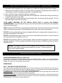
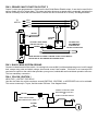
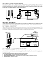
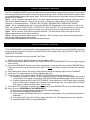
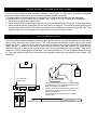
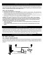
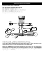
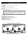
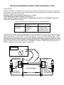
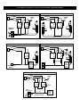
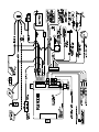
RS700 IIIER/RS701 III
SERIES III
REMOTE ENGINE STARTING SYSTEM
INSTALLATION INSTRUCTIONS
This Remote Start Module provides the following features:
SELECTABLE ENGINE SPEED SENSING:
• Tach, Semi-Tachless, & Vacuum
TACH AMPLIFIER:
• For dirty or low-level tach signals
PROGRAMMABLE RUN TIME:
• 10, 20, or 40 minutes
4 ON-BOARD RELAYS:
• Main Ignition (IGN1)
• IGN2 / Accessory
• Starter
• Parking Light
TWO PROGRAMMABLE MULTIFUNCTION OUTPUTS FOR:
• OEM Alarm Disarm
• Throttle Pulse for Carbureted vehicles
• Starter Disable / Anti-Grind Output
• Remote output for trunk pop
• Host alarm sensor disable
• Defroster Activation
HOOD / BRAKE SAFETY CIRCUITRY
VALET MODE / OVERRIDE
OEM ALARM / KEYLESS ACTIVATION:
• Lets a Factory Keyless Entry or Alarm
AUX output activate the Remote Start
REMOTE KEYLESS ENTRY:
• Controls power door locks
DIESEL START COMPATIBILITY
SECURITY STARTER DISABLE
DELAYED REMOTE CONTROL
OPERATION:
• Prevents accidental Remote Starts
TIMED SELF-START MODE:
• Program vehicle to start every
1-4 Hours
CODE / TACH LEARNING CIRCUITRY
Some of the features listed above are optional connections, and may require additional parts and labor.
TECHNICAL SUPPORT: 1-800-998-6880
Monday - Friday 8:00am - 4:30pm Pacific Time
Web Site: www.crimestopper.com
E-mail: [email protected]
CRIMESTOPPER SECURITY PRODUCTS, INC.
1770 S. TAPO STREET, SIMI VALLEY, CA. 93063
This device complies with FCC Rules part 15. Operation is subject to the following two conditions:
(1) This device may not cause harmful interference, and (2) This device must accept any
interference that may be received, including interference that may cause undesired operation. The
manufacturer is not responsible for any radio or TV interference caused by unauthorized
modifications to this equipment. Such modification could void the user’s authority to use the
equipment.
INSTALLATION CONSIDERATIONS / WARNINGS
To ease and reduce installation time, we suggest you consider the following points before starting.
1. Determine most suitable locations for all components to be placed. These components include: the
module itself, override / programming switches, and possible relays.
2. Use a Volt-Ohm meter to test and locate all connections.
3. Record all color codes of vehicle wiring to be used for reference. This will save time by not having to
re-test the same wires over again.
4. Allow enough wire to create a service loop with strain relief, should servicing be required. This will
also allow easier access and mounting.
**FOR SAFETY REASONS, DO NOT INSTALL RS700 III/901 in vehicles with MANUAL
TRANSMISSIONS** If accidentally left in gear, a remote started vehicle could become a self-propelled
threat to life and property.
DON'T extend the RS-900 Remote start ignition harness length. Mount the module so that main harness
reaches all ignition switch wiring. Extending these wires could result in poor performance.
DO NOT route any wiring that may become entangled with brake, and gas pedals, steering column, or
any other moving parts in the vehicle.
DO NOT exceed the rated output current of any circuit on the Remote start module. Failure to observe
this warning will result in damage to the unit.
DO NOT remote start the vehicle in a closed garage. Make sure that the garage door is open or there is
adequate ventilation. Failure to observe this rule could result in injury or death from poisonous Carbon
Monoxide fumes.
Warning: This system DOES NOT HAVE engine over-rev protection. Make certain
vehicle throttle linkage operates properly and does not stick. A stuck throttle will
cause severe engine damage
WIRING INSTRUCTIONS
PROGRAM/OVERRIDE SWITCH: 2 PIN PLUG
This switch is used primarily for programming features of the RS700 III/901. However, if the Anti-Grind/Starter
disable feature is installed, you MUST INSTALL this switch. This switch will allow the user to override the starter
disable in the event of a non-operating remote control.
8 PIN PLUG:
PIN 1: TAN: MULTI-FUNCTION OUTPUT 1
This output comes pre-programmed to provide a ground pulse to disarm the vehicles' FACTORY anti-theft system
prior to ignition on and 2 seconds after start for Defroster activation. This output can also be changed to operate as
a Remote controlled output for trunk release. See Programming Section.
For OEM Disarm: Connect this wire to the vehicles' anti-theft disarm wire. This wire is usually found coming off the
Driver's door key switch or the Factory Anti-theft control module.
For Defroster Activation: Connect this wire to the vehicle's defroster activation switch. It may be necessary to use
a relay. If using both OEM Disarm and Defrost Activation, Use relays to isolate the two circuits from operating
simultaneously, or use diodes to isolate interference.
PIN 2: ORANGE: MULTI-FUNCTION OUTPUT 2
Output 2 comes pre-programmed to operate as the Anti-Grind/Starter Disable output. It can also be used for the
sensor disable circuit for a host alarm. This output activates whenever a remote start is requested, and when the
vehicle is remotely locked with the transmitter. Connect this wire to terminal 85 of a relay. See diagram below.
TO
MOTOR
IGN 1
IGN 2
ACC
START
CUT
BROWN
OPTIONAL
RELAY
OPTIONAL 1N4001 DIODE
USE WITH LED ONLY
ORANGE
85
86
OPTIONAL LED
RECOMMENDED
FOR VEHICLES
WITHOUT DOORLOCKS
MAKE CERTAIN TO CONNECT "BROWN" START OUTPUT WIRE TO
MOTOR SIDE OF ANTI-GRIND/START DISABLE RELAY.
PIN 3: BLACK: MAIN SYSTEM GROUND
Connect to chassis metal of the vehicle. An existing bolt or screw MAY provide an adequate ground, or drill a small
hole, scrape away paint and attach using a sheet metal screw & star washer. If this wire is not connected OR
connected to a point on the vehicle that provides a poor ground, undesirable and inconsistent operation will occur.
This is a mandatory connection.
PIN 4: YELLOW: IGNITION 1
NEGATIVE (-) OUTPUT FOR RELAY
Use this wire when the vehicle requires a second IGNITION1, IGNITION2, or ACCESSORY wire to be activated.
This occurs commonly in Toyota, and late model GM cars. See diagram below:
CONNECT TO "GRAY IGN 2" WIRE
WHEN WIRING RELAY FOR IGN 2
OR
CONNECT TO BATTERY FOR IGN 1
YELLOW
INSERT DIODE AS SHOWN
85
86
30
87
WHEN CONNECTING FOR "IGN 2"
2nd IGN 1
OR
2nd IGN 2
+
BATTERY
PIN 5: GREEN: (-) START ACTIVATION TRIGGER
This wire allows a host alarm (-) Negative Auxiliary Channel Output to activate a Remote Start or it can be
connected to a Negative wire of a factory keyless entry system. If the Factory Keyless Entry System wire can
produce a Negative output for 1 second or 3 short pulses within 5 seconds, that system could also be used to trigger
a remote start. See diagram below for Factory Keyless interface.
L
L
UL
GREEN
85
87
30
86
UL
FACTORY
LOCK
RELAYS
+12V LOCK WIRE
PIN 6: GRAY: - HOOD SWITCH
Connect this wire to a switch that is at ground when the hood is open. If an existing switch is not available, then one
must be installed. When this wire is grounded, the remote start is inhibited. This is a mandatory connection!
PIN 7: PURPLE: + BRAKE RESET
Connect PURPLE wire to the side of brake pedal switch that shows +12 volts ONLY when pedal is depressed. This
will turn off the remote start if someone attempts to drive the car without the keys or if the Ignition key is not turned
on all the way. Brake pedal must be pressed for at least 1 second before reset will occur.
DIESEL
WAIT TO START
LAMP
1N4005
WAIT
INSERT DIODES WHEN USING BOTH
PURPLE
1N4005
+IGN
30
87
85
86
(-) DIESEL
WAIT TO START
LAMP
WAIT
NEGATIVE "WAIT-TO-START" WIRING
PIN 8: RED/WHITE: (+/-) TACHOMETER/VACUUM SENSE
This wire MUST BE CONNECTED to the vehicle to sense the engine running. This is so the control module can
control the starter motor to determine when to disengage the starter and to prevent the starter from engaging when
the engine is running.
This system has three methods of sensing an engine running condition:
• True Tach Learning: This is the best and most reliable method.
• Semi-Tachless/Timed Starting: An alternative for vehicles with hard to locate tach sources.
• Vacuum Sensing: When all else fails.
TACH LEARING MODE
The TACH LEARNING MODE is the most reliable and consistent method of engine speed sensing. This wire looks
for the pulsing signal that is created to monitor the engine speed or fire the coil. Most modern ignition systems utilize
a crankshaft sensor to monitor the engine speed. There are 4 different types of signals that may provide adequate
signal for TACH SENSE:
Type 1 - will be a computer-controlled ignition. On these systems the engine speed reference (tach) may come
from several possible locations. The wire may be found at: Distributor, Ignition Module, Coil Pack, Engine
Computer, or Crankshaft Sensor. THIS WILL BE THE MOST RELIABLE AND CONSISTENT SIGNAL.
Type 2 - will be a standard ignition coil. Connect the RED/WHITE 22-gauge wire to the negative (-) side of coil.
Note: The coil MAY NOT BE A GOOD LOCATION FOR TACH SOURCE. The coil wire may be too noisy for the
system to detect a clean signal and/or the vehicle uses a Multi-spark ignition system that varies the spark.
Type 3 - will be computer controlled fuel injection solenoids. This wire can be found at the Injectors in the
engine compartment or at the engine computer.
Type 4 - will be the Alternator Stator pins on the alternator. This is found on many GM and Ford Diesel trucks
from the mid 1980's through the mid 1990's.
Use the Tach Finder Mode below to locate your tach source wire.
TACH-FINDER MODE
TACH-FINDER MODE is a unique feature to help installers easily identify wires that may be POSSIBLE sources for
an engine speed reference by using the same RED/WHITE wire to probe ANY wiring, WITHOUT RISK TO THE
COMPUTER SYSTEMS.
Following the procedure below may operate Tach-Finder:
1) OPEN HOOD (ground GRAY hood switch wire) and Start engine.
2) Depress and Hold the BRAKE PEDAL and THEN PRESS THE PROGRAM BUTTON until the parking lights
come on solid.
3) Connect the RED/WHITE tach wire to a scribe or sharp probe. It may be necessary to extend RED/WHITE wire.
Probe the wires that may provide the proper signal. Warning: be certain to protect yourself from electrical
shock!!
4) Start probing wires, when a wire with a pulsing signal is probed, the parking lights will start FLASHING.
5) At this time, turn engine/ignition off. Parking lights will stay ON.
6) Verify tach signal. Turn Ignition ON but DO NOT START ENGINE and probe the same wire.
A) If parking lights start FLASHING, you have found a DATA wire. This wire will tell the system the engine is
running even if it the engine is not running. RESTART ENGINE and Repeat steps 4-6 with another wire.
B) If parking lights stay SOLID then START ENGINE. If park lights stay on SOLID after engine is started,
there is no tach source. Repeat steps 4 through 6 to locate another wire. If park lights start FLASHING
after engine is started, the tach source may be valid.
7) Turn engine OFF, park lights will remain ON. Permanently connect RED/WHITE wire to the located tach lead.
8) Now it is time to PROGRAM the TACH REFERENCE:
A) Start engine (with hood open), parking lights should start flashing.
B) Depress and hold BRAKE PEDAL down.
C) Press and hold PROGRAM SWITCH for 2 seconds. Parking lights will stop flashing while button is
depressed.
D) Turn Ignition OFF, close hood. Parking Lights will still be ON. Tach Programming is now complete.
E) Depress BRAKE PEDAL to clear parking lights.
TACH WIRE TROUBLESHOOTING
If all remote start wiring has been completed, attempt a remote start. If engine starts, and starter disengages
quickly, and engine continues to run, the tach wire has been properly connected.
** If system does not remote start properly, you will have to locate a different tach wire and reprogram.
AN INADEQUATE TACH SOURCE WILL PRESENT ANY VARIETY OF THE FOLLOWING PROBLEMS:
• Starter stays engaged after engine starts.
• Starter releases properly when engine starts, but engine then stalls BEFORE the time out. System may re-start.
• Starter releases properly, and engine runs, but then starter re-engages. (This makes a terrible grinding noise
and the system must be shut off as quickly as possible to prevent damage to starter and flywheel). See "Tach
Amplifier" below and on next page for other alternatives in solving starting problems!
TACH AMPLIFIER
The Tach Amplifier feature is capable of detecting engine speed inductively (not connected directly but rather placed
next to) from a spark plug wire or other source. This Tach Amp also has the ability of picking up very low voltage
signals (as low as 1 volt) from vehicle computer modules, which more and more are driving the Tachometers in
newer vehicles. In addition to the ability to detect signals inductively, the tach amplifier also conditions and
smoothes the signal to prevent spiking and glitches from influencing the Remote Start processor. Tach amp is
turned on or off by a jumper plug on the unit next to the harness connectors. The unit is shipped with the tach amp
off. Tach amp should be used only in cases where an acceptable factory tach wire cannot be easily located. SEE
DIAGRAM.
+
-
COIL
TACH AMPLIFIER
JUMPER PINS
TACH WIRE CAN BE PLACED NEXT TO OR WRAPPED
AROUND THE MAIN COIL WIRE OR ANY SPARK PLUG
WIRE. SEE BELOW FOR SAMPLES.
THERE IS NO GUARANTEE THAT THIS TYPE OF TACH
SENSING WILL WORK. HOWEVER, IT PROVIDES
ANOTHER POSSIBILITY.
JUMPER PLUG
CONNECTION
TACH
AMP
ON
TACH
AMP
OFF
TOP VIEW
ATTACH WIRE USING HI-TEMP PLASTIC CLAMPS
OR WIRE TIES.
RED/WHITE WIRE
COIL OR SPARK PLUG WIRE
SEMI-TACHLESS MODE
This new feature provides an easy method of starting the vehicle without locating the exact tach wire required. It
uses a timed crank output combined with the tach wire as a crude pulse monitor. This combination prevents the
starter from engaging into an already running engine and provides a reliable method of detecting when restart is
required. There are 4 different crank times available for use.
HOW TO USE THIS FEATURE:
1) Program the "Engine Sense" for "Timed Crank".
2) Next program the "Crank Time" to the appropriate time required for engine starting. This is determined by
starting the engine with the key and estimating the amount of time it takes before the engine begins to run. We
recommend starting with the minimum time, which is already preset for 0.75 sec.
3) Connect the RED/WHITE tach wire to ANY negative coil trigger wire, OR see Tach Amplifier instructions on
previous page. The system is now configured for Semi-Tachless operation.
WARNING: This method of starting the vehicle is not as reliable as using the TRUE TACH LEARNING.
This method should be used only in the event that a tach wire cannot be located using the normal tach
programming and tach amplifier. When using this method, there may be certain operating anomalies
requiring seasonal adjustments. These are, but not limited to:
• Starter may under crank in extreme cold weather. Vehicle may start on 2nd or 3rd attempt, or will
require programming.
• In warm weather starter may tend to over crank, and may require reprogramming from the winter
setting.
VACUUM SWITCH
This is to be used only in the event that a tach sense wire cannot be found. A simple Vacuum controlled switch,
installed on the intake side of the engine, is used to signal the starter module that the engine is running. When the
engine is NOT running, the switch rests at ground. When the engine starts, the engine vacuum opens the switch
causing the ground to go away. This tells the starter module the engine is running. Connect Vacuum Switch per the
instructions included with switch. Vacuum mode is programmable. Make certain tach amplifier is off.
3 PIN GREEN ACCESSORY PLUG
PIN 1: EMPTY, PIN 3: EMPTY
PIN 2: ORANGE: OEM RE-ARM WIRE
This wire provides a negative output in sequence with the lock pulse of the system. This wire is to be connected to
the door pin switch wire to simulate a door being open when the system is locking in order to ARM some types of
OEM Factory Security Systems. This wire can be connected directly to a Negative OEM arming wire if one is
available.
ORANGE
30
87
86
85
DOME
LIGHT
NOTE: OBSERVE PROPER POLARITY WHEN CONNECTING TERM. 87
IGNITION SWITCH WIRING
6 PIN HIGH-CURRENT SPADE CONNECTORS:
PIN 1: RED 14Ga.: BATTERY CONSTANT FUSED 30A
PIN 2: BROWN 14Ga.: STARTER OUTPUT - 30A
PIN 3: GRAY 14Ga.: IGNITION 2 - 30A
PIN 4: WHITE 18Ga.: + PARKING LIGHTS 10A SEE NEXT PAGE
PIN 5: PINK 14Ga.: IGNITION 1 - 30A
PIN 6: RED 14Ga.: BATTERY CONSTANT FUSED - 30A
See diagram below for connection information:
PARKING
LIGHTS
RED
WHITE
FUSE
30A
RED
+10A MAX.
FUSE
30A
+
FUEL
PUMP
+
ENGINE
ECU
PINK
BROWN
GRAY
-
BATTERY
STARTER
-
COIL
IGN 1
TRANSMISSION
ECU
2nd IGN 1
OR
2nd IGN 2
IGN 2
H/V/AC
SPADE PIN 4: WHITE: (+) PARKING LIGHT OUTPUT [10 AMP MAX.]
(WHITE OUTPUT WIRE MUST BE FUSED OR SERIOUS DAMAGE MAY OCCUR.)
On most AMERICAN and JAPANESE vehicles, the parking lights will operate on a single fused circuit. You may
connect WHITE wire directly to the wire of any parking light or at main lighting switch.
NOTE: Some JAPANESE vehicles use a negative triggered relay to activate parking lights. Use a relay to convert
to ground switch or tap into the positive circuit of the parking lights after the Factory relay. On most EUROPEAN
vehicles, the light circuits are separately fused for left and right. Each circuit must be individually connected and
isolated from one another. This can be done by using two (2) 6A05 6 Amp diodes, OR one (1) BOSCH SPST dual
output relay (part no. 0-332-015-001).
POWER DOOR LOCK WIRING
3 PIN DOOR LOCK PLUG:
PIN 1: GREEN:
Sends a (-) Negative pulse for LOCK; Sends a positive pulse for UNLOCK
PIN 2: RED:
+12V Coil Power for external relays TERM 86. (If needed.)
PIN 3: BLUE:
Sends a (-) Negative pulse for UNLOCK; Sends a positive pulse for LOCK
DETERMINING DOOR LOCK TYPE:
WARNING: You must determine the type of locking system the vehicle has before connecting
any wires. Incorrect connection will result in damage to the remote start and/or vehicle locking
system. Use 1-amp diodes as shown in the diagram below when tapping into a Factory
Positive or Negative door lock system to protect the output transistors against a dead short
from some types of Factory locking systems.
There are several types of door lock systems in vehicles today. Below is listed the many types of common
locking systems:
Negative trigger: Most Japanese; Ford, New GM
Positive trigger: Many GM; Some Dodge/Chrysler/Plymouth
One wire dual voltage: Newer Dodge/Chrysler/Plymouth; Ford Probe
Reverse Polarity: Dodge/Chrysler/Plymouth; GM; Ford
Ground/open: Some Nissan; Subaru
Semi-automatic: Older Saab and Volvo
Electric vacuum pump: Pre 1995 Mercedes-Benz
DOOR LOCK DIAGRAMS WITH FACTORY RELAYS
NEGATIVE TRIGGER DOORLOCK WIRING
GREEN
GREEN
RED
RED
BLUE
BLUE
L
UL
POSITIVE TRIGGER DOORLOCK WIRING
IN4001
IN4001
DIODES
DIODES
LOCK
UNLOCK
FACTORY
POWER
LOCKING
RELAYS
L
UL
LOCK
UNLOCK
FOR ADDITIONAL DIAGRAMS - SEE PAGE 11
FACTORY
POWER
LOCKING
RELAYS
TESTING FOR REVERSE POLARITY DOOR LOCKS WITH A VOM
(5-wire switch)
Reverse Polarity Door Lock Systems are a series circuit in which one switch serves as a "master" source for the
motor grounds. When any switch in the circuit is pressed, one of the grounds is "lifted" and voltage is applied to the
open circuit causing the locks to activate.
Set meter to VOLT scale sufficient to measure up to 15 volts.
Connect RED meter probe to constant +12 volt source.
Locate the door lock wires in either the driver or passenger’s kick panel. Use the BLACK probe of the
meter check the wires one at a time:
Common Wire Colors: (Use as a guide only, your vehicle may differ.)
FORD / LINCOLN
MERCURY
Pink/Lt. Green
Pink/Yellow
DODGE / CHRYSLER
PLYMOUTH
Orange/Violet
Pink/Violet or
Orange*
Pink*
*There may be (2) wires of the same color
GENERAL MOTORS
Lt. Blue
Dark Blue or Black
Black/White (Trucks)
Black/Red (Trucks)
Connect meter to first wire, meter should read about 12 volts. Press the LEFT door lock switch to the lock position,
and then unlock position. Now presses the RIGHT door lock switch to the lock, and then unlock positions. If BOTH
SWITCHES make the wire read 0 volt, it is the WRONG WIRE (it's a motor wire). TRY ANOTHER WIRE. If ONLY
ONE SWITCH makes the meter read 0 volt, then it is the CORRECT WIRE and that switch is the "MASTER". When
meter reads 0 Volts when LOCK is pressed, that wire is the LOCK wire. If Meter Reads 0 Volts when UNLOCK
position is pressed, that wire is the UNLOCK wire. REMEMBER - CORRECT WIRES will show 0 volts from ONLY 1
SWITCH. Repeat the test procedure above for second wire.
12. 0 +
COM
DCV
AC
V
V-
OFF
DRIVER'S DOOR
MASTER SWITCH
PASSENGER DOOR
LOCK SWITCH
+12V
VEHICLE INTERIOR
LEFT DOOR
LOCK MOTOR
DOOR JAMBS
RIGHT DOOR
LOCK MOTOR
POWER DOOR LOCK WIRING DIAGRAMS
REVERSE POLARITY DOOR LOCK WIRING
AFTERMARKET MOTOR/DOOR LOCK WIRING
GREEN
GREEN
FUSED
+12V
+
RED
BLUE
85
86
87
87A 30
85
FUSED
+12V
+
RED
BLUE
85
86
86
87
87A 30
87
87A 30
85
86
87
87A 30
MASTER
SWITCH
+
L
CUT
UL
CUT
GROUND/OPEN LOCKING SYSTEM
ONE WIRE / DUAL VOLTAGE SYSTEM
GREEN
RED
BLUE
GREEN
RED
BLUE
+
85
85
86
86
85
87
30
87
87A 30
86
87
30
FUSED
+12V
RESISTORS
DOOR MICRO
SWITCH
FACTORY
POWER
LOCKING
RELAYS
FACTORY
POWER
LOCKING
RELAYS
L
UL
MERCEDES-BENZ VACUUM SYSTEM
GREEN
FUSED
+12V
+
RED
BLUE
85
86
87
87A 30
85
86
87
87A 30
DOOR
MICROSWITCH
CUT
BLUE or YELLOW
WIRE IN KICK PANEL
GROUND
CENTRAL
LOCKING
PUMP
MOTOR
PROGRAMMING
CODE LEARNING PROGRAMMING:
The RS700 IIIER will learn up to 4 different transmitter security codes. This procedure does not apply to the RS701
III add-on Remote Start module.
Transmitter Programming:
1)
2)
3)
4)
5)
6)
7)
Open Hood (Gray wire grounded).
Depress and Hold BRAKE PEDAL, and then Press Program Button until parking lights turn ON solid.
Release program button.
With BRAKE Depressed, Press and Hold program button again.
Within 4 seconds press the button on the remote that will be the remote start button transmitter.
Parking lights will flash once to confirm programming. Release Remote and Program button after confirmation.
CLOSE HOOD FIRST, Then press and release BRAKE PEDAL to clear parking lights.
Tach Reference Programming:
1) Open Hood (Gray wire grounded), Start Engine.
2) Depress and Hold BRAKE PEDAL, and then Press Program Button until parking lights turn ON flashing.
(Tach-Finder mode is now engaged).
3) Release program button.
4) With BRAKE Depressed, Press and Hold program button again, parking lights will be on solid (not flashing).
Tach reference is now learned.
5) Release Program Button, Parking Lights will begin flashing again.
6) CLOSE HOOD FIRST, Then press and release BRAKE PEDAL to clear parking lights.
Programmable Options:
This system has several installer programmable features. Below is a brief description of these features.
Option #1 - Crank Time:
This programs the amount of time the starter cranks. This programming works ONLY when Option #2 (Engine
Sense) is programmed to Value 2 (Timed Crank).
Option #2 - Engine Sense:
This programs the TYPE of Engine monitoring the system uses. Value 1 (Tach sensing) is the most reliable and
accurate. Value 2 (Timed Crank) is for "Semi-Tachless Mode” when there is an only poor or dirty tach signal that
cannot be cleaned up. Value 3 (Vacuum) this requires installing an additional Vacuum Switch.
Option #3 – Remote Auxiliary Output:
This programs the remote output of the system for activating a trunk release. Value 1 is No Output. Value 2
enables the output to operate on Multi-Function Output Wire #2 (Orange wire). Value 3 enables the output to
operate on Multi-Function Output Wire #1 (Tan wire).
Option #4 - Double Unlock Pulse:
Programs UNLOCK Pulse to be either a single or double pulse. Makes the installation into vehicles such as
Nissan's and Volkswagens that require an additional pulse for Factory DISARM very easy.
Option #5 - Lock after Remote Start TIME-OUT or ABORT:
Programs system to re-lock power door locks after remote engine start turns off. This is to ensure that vehicles,
which come equipped with factory ignition controlled door locks, will not leave the vehicle unlocked. (Many GM’s
such as Buick)
Option #6 – Run Time:
Program the desired run time for remote start. The programmed run time also applies to the Idle-Down feature.
Value 1 is 10 min., Value 2 is 20 min., and Value 3 is 40 min.
SEE PROCEDURE and CHART on NEXT PAGE for EASY OPTIONS PROGRAMMING.
PROGRAMMING
Options Programming:
1)
2)
3)
4)
5)
Open Hood (Gray wire grounded) Depress and Hold BRAKE PEDAL.
Press and Release program button. (Parking lights come on.)
Wait 2 seconds, then press and release brake pedal again.
Release BRAKE PEDAL
Momentarily Press then Release program button the number of times for the option program level desired.
Parking lights will flash the same number of times to confirm the program level.
6) Press then Release BRAKE PEDAL to increment the option value. Parking Light flashes will equal Option Value
setting to confirm programming.
7) When finished programming, CLOSE HOOD FIRST, Then press and release BRAKE PEDAL to clear parking
lights.
PROGRAMMING OPTIONS CHART
Prog. Level
Option Description
Option Values
#1
Crank Time (in seconds)
#2
Engine Sense
#3
Remote Aux. Output
#4
Door Unlock Pulse
#5
Lock After R.S. Time/Out (Abort)
#6
Run Time
1 = 0.75 secs.
2 = 1.25 secs.
3 = 1.75 secs.
4 = 2.25 sec.
1 = Tach
2 = Timed Crank
3 = Vacuum
1 = Not Active
2 = Directed to Orange
3 = Directed to Tan
1 = Single Unlock Pulse
2 = Double Unlock Pulse
1 = Disabled
2 = Enabled
1 = 10 Min
2 = 20 Min
3 = 40 Min
Fac. Pre-set
1
1
1
1
1
2
EXAMPLE:
Program Remote Aux. output (Trunk Pop) channel to TAN Multi-Function wire.
1)
2)
3)
4)
5)
6)
Open Hood. Depress and Hold BRAKE PEDAL.
Press and Release program button. (Parking lights come on.)
Wait 2 seconds, then press and release brake pedal again.
Release BRAKE PEDAL
Momentarily press then Release program button 3 times. Parking lights should flash 3 times.
Press BRAKE PEDAL twice to get from option value #1 (default) to Option value #3. Parking Lights will flash 3
times to confirm you are at option 3.
7) Close hood, then press the brake pedal to clear.
8) The TAN wire should now be a negative output when the Trunk channel on Transmitter is pressed for 1 second
or longer.
+