1
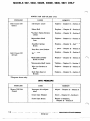
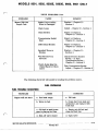
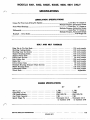
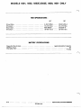
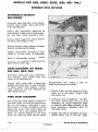
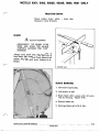
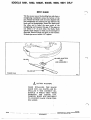
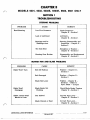
SECTION 1
TROUBLESHOOTING
STEERINGPROBLEMS
PROBLEM
Hard Steering
REMEDY
CAUSE
Low Tire Pressure
Check Pressure
Chapter I1 Section 1
Lack of Lubricant
Lubricate
Chapter I1
Section 1
Bearings and/or
Bushings worn
Steering Disassembly and
Inspection Chapter I1
Section 2
Tie Rods Bent
Straighten o r Replace
Chapter I1 Section 2
Steering Gear Broken
Disassembly and Replacement
Chapter I1 Section 2
MOWER PAN AND BLADEPROBLEMS
PROBLEM
CAUSE
REMEDY
Belt Off Pulleys
Replace Chapter
Section 3
I1
Belt Damaged
Replace Chapter
Section 3
I1
Blade Nut Loose
Tighten Chapter 11
Section 1 Refer to
Spec. Sheet -- Torque
Blade Won't
Disengage
Blade Brake Not
Working
Check Blade Brake Tension
Chapter I1 Section 3
Blade Leaves Swirl
Marks in Lawn
Pan Unlevel
Correct Pan Level
Chapter I1 Section 3
Blade Unlevel o r Bent
Correct Pan Level
Chapter I1 Section 3
Blade Won't Turn
ONLY
MODELS 9301,9302,9302E,9303E,9600,9601
MOWER .PAN AND BLADECont.
PROBLEM
Belt Comes Off
(Rear)
Belt Comes Off
(Front)
CAUSE
REMEDY
Belt Keeper Loose
Tighten Chapter
I1
Section 3
Broken Belt
Replace Chapter
I1
Section 3
*Top Idler Pulley Broken
o r Bent
Replace Chapter
I1
Section 3
*Intermediate Shaft
Loose
Tighten Chapter
I1
Section 3
Rear Idler Spring
Broken
Replace Chapter
I1
Section 3
Rear Idler Arm Broken
Replace Chapter
I1
Section 3
Broken Belt
Replace Chapter
I1
Section 3
*Bottom Idler Pulley
Broken o r Bent
Replace Chapter
11 Section 3
*Intermediate Shaft Loose
Tighten Chapter
I1 Section 3
Idler Arm Broken o r
Bent
Replace Chapter
I1 Section 3
Belt Pulley Bent o r
Broken
Replace Chapter
I1 Section 3
*Diagram shown only.
DRIVE PROBLEMS'
I
PROBLEM
Mower Will Not
Propel
REMEDY
CAUSE
Improper drive adjustment
Adjust
Drive Disc Polished
Score Chapter
Drive Disc Broken
Repair o r Replace,
Chapter I1 Section 4
Chapter I1 Section 4
I1 Section 4
SERVICEBULLETINREFERENCES
11-18
REVISED 1977
MODELS 9301,9302,9302E,9303E,9600,9601ONLY
DRIVEPROBLEMSCont.
PROBLEM
Mower Will Not
Propel Cont.
CAUSE
REMEDY
Rubber Drive Roller
Worn o r Damaged
Replace Chapter
Section 4
Chain Loose
Adjust
Chain Broken
Repair o r Replace,
Chapter I1 Section 4
Transmission Rod(s)
Bent
Repair o r Replace,
Chapter I1 Section 4
Differential Broken
Repair o r Replace,
Chapter I1 Section 4
Sprocket Worn o r
Broken
Replace Chapter
Section 4
Will Not Drive In
Check Reverse Booster
Spring o r Disc.
Compression Spring
Chapter II Section 4
Reverse
Clutch Pedal Must Be
Pulled Back for More
Drive
I1
Chapter I1
Section 4
I1
Disc Compression Spring
Adjust Chapter II Section 4
The following check list will assist in locating the problem source.
FUEL PROBLEMS
FUEL TROUBLE SHOOTING
TROUBLES
Engine will not start
CAUSES
REMEDIES
a. Fuel tank empty
a. Fill tank
b. Water in fuel
b. Drain fuel from tank and
carburetor and replace with
fresh fuel
c. Old fuel in tank forms
gum to plug up fuel line
c. Empty out old fuel and
clean out fuel line
d. Shut-off valve closed
d. Open valve
MODELS 9301, 9302, 9302E, 9303E, '9600, 9601 ONLY
FUEL PROBLEMS Cont.
~-
Engine slows down
and stops
REMEDIES
CAUSES
TROUBLES
a. Unplug hole
a. Vent hole in fuel tank
cap plugged
i b. Clean out fuel line o r
b. Fuel line or strainer
clogged
strainer
c. Refill tank
c. Fuel tank runs dry
IGNITION PROBLEMS
SPARK PLUG TROUBLE CHART
PLUG CONDITION
Black carbon o r
sooty deposit
CAUSES
RECOMMENDATION
a. Breaker points dirty or
out of adjustment
a. Clean and adjust gap
b. Weak condenser
b. Check and replace if
weak
I
-
c. Incorrect plug
C.
Install correct plug
Pitted o r burned
points, white, light
tan or blistered deposits. Rapid wear
of points
a. Incorrect plug
a. Install correct plug
Cracked o r broken
Plug
a. Careless installation of
Plug
a. Replace plug
Cracked or broken
insulator on lower
end of plug
a. Center electrode
strained when regapping
Plug
a. Replace plug
Widening of gap
a. Normal wear
a. Clean and regap
Disc
MODELS 9301,9302,9302E,9303E,9600,9601
ONLY
SPECIFICATIONS
LUBRICATION SPECIFICATIONS
Boy “A” Grease or
Multiple Purpose, Automotive Grease
Lawn-Boy“A” Grease or
Multiple purpoSe,Automotive Grease
“A” Grease or
Multiple purpoSe, Automotive Grease
#30 Weight Oil
Grease For Front Axle& King Pin Spindle
Front Wheel Bearings
Differential Lawn-Boy
Hexshaft Drive Roller
BOLT AND N U T TORQUES
Bolt
King Pin to Tie Rod Nuts 135 inch pounds
Steering Casting Bolts. 135 inch
Steering Gear Set Screw 135 inch pounds
Engine Mounting Bolts. 135 inch pounds
Engine Pulley
Drive
Belt Pulley Nut. 250
Blade Nut600
DriveRoller Nuts
Hexshaft Bearing Retainer Plate Screws
Wheel Bearing Bolts 175 inch pounds
Differential Bolts 135 inch
Wheel NutsAdjustable
pounds
pounds
pounds
250 inch
90 inch
inch pounds
inch pounds
90 inchpounds
35 inch pounds
pounds
ENGINE SPECIFICATIONS
Idle r.p.m.
Operating r.p.m.
Oil Requirements
Gas Tank Capacity
Spark Plugs #‘s
SERVICE BULLETIN REFERENCES
26”
30”
1,750
3,650
SAE10W/30
2 Qt.
Champion CJ-8
o r Autolite A7N
1,750
3,650
SAE 10W/30
2 Qt.
Champion CJ-8
o r Autolite A7N
11-21
REVISED 1977
;9600, 9601 ONLY
MODELS 9301,9302,9302E,9303E,
TIRE SPECIFICATIONS
4.10/3.50~4
15-17 P.S.I.
480/400x8
22-25 P.S.I.
Front Size.
Pressure
Rear Size
Pressure
10x5/4.50-4
15-17 P.S.I.
16~5.50-8
22-25 P.S.I.
BATTERY SPECIFICATIONS
Approximately 2 quarts
24
3 amp
Capacity Electrolyte
Ampere Hour
ChargingRate
SERVICE BULLETIN REFERENCES
REVISED 1977
MODELS 9301,9302,9302E,9303E,9600,9601
ONLY
SECTION 2
HOW TO REPAIR AND REPLACE
STEERING
To insure trouble-free operation, use a grease gun and
apply a good quality automotive chassis lubricant to
the five zerk fittings. (Figure 2-1). Or Lawn-Boy “A”
grease.
A positive type steering system is employed. The steer-
ing arm is keyed to the steering shaft and secured with
a setscrew. The steering gear is linked to the left side
spindle and kingpin arm. A tie rod connects the
wheels.
As you disassemble the front end, watch for bent or
mis-shaped rods, dry bearings, bearings or bushings
which are damaged, and shafts which are gouged or
grooved.
FIGURE 2-1
SERVICE BULLETIN REFERENCES
11-23
REVISED 1977
MODELS 9301,9302,9302E,9303E,i9600,9601
FIGURE 2-3
ONLY
04238
11-24
SERVICE BULLETIN REFERENCES
REVISED 1977
MODELS 9301,9302,9302E,9303E,9600,9601
ONLY
STEERINGDISASSEMBLY
SPINDLE A N D / O R KING PIN
REMOVAL
Disconnect
the
spark plug
lead.
Remove
thebattery,(electric
start models only.)
Stand mower on tilt (knurfing) bar.
Remove front wheel. Remove tie rods from
kingpin arm.Drive out roll pin. Remove
spindlefromsteeringcasting.
See Figures
2-3 and 2-4.
NOTE
FIGURE 2-4
RIGHT
94193
King pin a r m s a r e not identical (Figure 2-4). Care should betakento
reinstall them properly.
FRONT AXLE REMOVAL
Disconnectthespark
plug lead.Remove
thebattery(electric
start models only.) Stand
moweron tilt (knurfing) bar. Remove spindle andking pin. (See spindleand/or king pin
removal above.)
Remove snap ring from pivot pin. Drive pivot pin from steering casting and axle. Remove
axle.
STEERING CASTING REMOVAL
Disconnect spark pluglead.Remove
battery,(electricstart
models only.) Standmower
on tilt (knurfing) bar. Remove front axle.
Remove steering wheel and pedal support rod. Remove
two bolts securing steering casting
to main frame casting. Remove steering casting from main frame.
IMPORTANT NOTE: Later model bushings contain two ridges which match the grooves in the
frame castings. During reassembly the bushings
MUST BE placed in the same position they were
removed to prevent binding of the steering shaft.
See Figures 2-5Aand 2-5B. Loosen the setscrew on
the pitman arm. Using expansion pliers remove
the
retaining ring and remove
pitman arm.
CORRECT
FIGURE 2-5A
04267
RIBS IN
Disconnect spark pluglead.Remove
battery,
(electric
start models only.) Stand
mower on tilt (knurfing) bar. Remove steering casting.
I
INCORRECT
04268
STEERING CASTING DISASSEMBLY
FIGURE 2-5B
Remove all bolts holding castingtogether.
Casting halves can then be separated (Figure
2-5). Pull steering shaft from casting. Note
plastic bushings a r e ribbed for placement in
casting--do not clean with solvent.
The
steering gear is held to the steering shaft
with a retainer ring and a setscrew.
n
MODELS 9301,9302,
9302E, 9303E, 9600, 9601ONLY
FIGURE 2-6
94173
\
STEERING WHEEL ALIGNMENT
!
If steering wheel does not line up properly
with frontwheels,
it canbealigned
as
follows:
2. Loosen ,jam nut at ball joint socket
1. Remove nut securingballjoint
pin arm.
3. Assemble ball jointto
nut.
to king
and
turn ball joint on o r off rod until steering
wheel is aligned with front wheels. (Figure 2-6.j
king pin a r m and
MODELS 9301,9302,9302E,9303E,9600,9601
ONLY
SECTION 3
ADJUSTMENTS
POWERFORDRIVING
To effect transmission of motivepower to
the cuttingblade,
two V-belts a r e used.
The primary drive pulley which is located
above the drive disc is keyed to the engine
crankshaft. A short V-belt runsfromthis
primary pulley totheupper
pulleyon the
intermediate spindle. A' longer V-beltconnectsthelower
pulleyonthe intermediate
spindle to thebladepulley
on theblade
shaft, driving the cutting blade.
R
ULLEY
THE MOWERBLADE
Two idler pulleys areusedintheblade
drive system as illustrated below. A blade
brake applied to the short belt (rear) stops
the blade. The
brake is applied by the control lever.
As .the mower pan is disassembled, examine
rods and suspensionassemblyfordamage
or distortion, for bent o r misshapened rods,
bearings or bushings which a r e damaged o r
worn, drybearings,
and shafts which a r e
gouged o r ringed.
PRIMARY
BLADE
DRIVE
PULLEY
INTERMEDIATE
DRIVE
PULLEY DISC
PULLEY
FIGURE 2-7
DUAL
AND SPINDLE
94311
SERVICE BULLETIN REFERENCES
11-27
REVISED 1977
04242
SERVICE BULLETIN REFERENCES
11-28
REVISED 1977
MODELS 9301, 9302, 9302E,9303E.9600,
9601 ONLY
MOWER PAN DISASSEMBLY
PANREMOVAL
Remove belt, and bell arm shoulder bolts.
Remove front pan suspension bar shoulder
bolts. Pan can now be removed frommower.
FRONT BELT REMOVAL
Disconnect spark plug lead.
NOTE
1
I
REAR BELT REMOVAL
Use a rope as shown on Figure 2-10
when removing idler spring.
Remove belt.
Disconnect spark plug lead. Remove battery, (electric start models only). Remove
rear cover. Remove belt keeper(Figure
2-11); tighten tilt (knurfing) b a r bolts. Stand
mower on tilt (knurfing) bar.
Reassemble in reverse order
of disassembly.
SAFETY WARNING
SECURE TO WALL TO PREVENT
THE MOWER
FROM
TIPPING OR
FALLING.
Rollbelt
off the top intermediatepulley.
Pull belt between drive disc and
drive
roller.
Reassemble in reverse order
of disassembly.
FIGURE 2-11
IDLER A R M REMOVAL
~94181
Remove belt. Remove belt pulley. Remove
andreplace
idler arm. (See Figure 2-9.)
SERVICE
BULLETIN
REFERENCES
11-29
REVISED 1977
MODELS 9301,9302,9302E,9303E,'9600,9601ONLY
BLADE BRAKEADJUSTMENT
When the blade control
lever
is placed
in
the “off” position, an adjustable leaf spring
connected to the bell a r m and hub assembly
is forced against the drive belt preventing
the blade from rotating.
SAFETY WARNING
BLADE NUT MUSTBETIGHT
BEFORE ADJUSTING BLADE BRAKE
TENSION. SECURE MOWER TO
PREVENT TIPPING OR FALLING.
The
blade
brake leaf
spring
be adjustedto obtain blade stoppageinnot
less
than (4) four or more than (6) sixseconds
with engine operating at 3600 RPM.
1. Use a right
angle
screwdriver
to loosen
the lock screw on the blade brake leaf
spring. See Figure 2-12.
To obtain proper bladebrake tension:
2. Move the spring in o r out until desired
position,is obtained.
Disconnect spark Plug lead- Remove battery, (electric start models only.)
3. Tighten lock Screw
mower back on wheels.
Stand mower on tilt (knurfing) bar.
4. Start engine,letting
Lower
it run about (2) two
minutes'to warm up.
5. Place blade control lever in "off" position. Check bladestoppage by visually
observingdrive pulley. DO NOT place
FIGURE 2-12
94184
SERVICE
BULLETIN
REFERENCES
11-30
REVISED 1977
MODELS 9301,9302,9302E,
9303E, 9600,9601 ONLY
PAN TILT ADJUSTMENT- 26” & 30’’ MODELS
1. Locate the mower on a flat level surface
such as driveway,
a
sidewalk,
garage
floor, etc.
2. Place the height adjustment lever in the
middle setting.
3. Rotatethebladeuntilthecuttingedge
is
facing the front of the mower and measure the distance from the
ground to the
tip of thecuttingedge of the blade. See
Figure 2- 13.
180º and measure (from
r e a r of pan) the distance’ from theground
4. Rotate the blade
FIGURE 2-14
to the tip of the cutting edge of the blade.
See Figure 2-13.
5. Themower
pan tilt is Correct if the
step 4 is 1/4
measurementobtainedin
inchhigherthanthemeasurement
obtained in step 3.
6. The pan tilt may be adjusted by removing
the cotter pin on one end of the tilt adjust
rod, loosen the jam nut on the clevis and
turn the rod in o r out of the clevis until
the
required
tilt is reached. Secure
2-14.
clevis with jam nut. SeeFigure
7. See page 11-54 and check for bent blade.
94276
MODELS 9301,9302,9302E,9303E,9600,9601
ONLY
SECTION 4
THEORY OF OPERATION
INTRODUCTION
The Lawn-Boy Riding Mower is powered by a verticalshaftfour-cyclegasolineengine
mounted on the rear of the machine. The vertical crankshaft of the engine drives both the
wheels and the cutting blade, with the speed of the forward motion determined by the Speed
Selector Lever which provides three forward speeds, a reverse, and a neutral position. The
speed of the cutting blade on the mower is determined by the revolutions per minute of the
engine. The throttleallowsvaryingspeeds
of theengine up to a maximum of 3600 rpm.
Because of the selective controls of the Rider, it is possible to drive the machine without the
cutting blade rotating, to drive the wheels slowly
while the cutting blade and engine are at
full 3600 rpm for maximum cutting in heavy growth, and to regulate from the driver's seat
many combinations of speed and cutting heights.
FIRST
POSITION
FIGURE 2-15
94316
POWERFOR
DRIVING THEWHEELS
The driving of the wheels is accomplished through the use of a large aluminum drive disc
which is keyed to the vertical crankshaft of the engine. Because this disc always rotates at
the speed of the engine, transfer of motive power at varying speeds is accomplished through
the use of linkages, by bringing the rubber-tired drive roller into contact
with the disc at
three different positions from the center
of the disc. The linear speed of any pointon a
wheel is highest when the point is at the rim andslowest at the hub. The first position
MODELS 9301,9302,9302E,9303E,9600,9601
ONLY
shown, Figure 2-15, is nearest the center and is theslowestspeed, or First. Thesecond
position shown, Figure 2-16, produces a higherspeed, o r Second, and the third position,
Figure 2-17, near the rim of the disc produces the highest speed, or
Third. In third position,
the Rider will travel at approximately 6 mph. It is also characteristic of a rotating disc to
transmit power in either direction, depending upon which side of the disc is brought into contact with the drive roller. The drive roller is shown, Figure 2-18, in contact with the disc on
the opposite side of center. Note that the drive roller is quite close to the center for lowspeed,safe backing. In neutralposition,Figure 2-19, the' ,drive roller is not in contact with
the drive disc.
SECOND
POSITION
\
FIGURE 2-16
94317
The use of the large aluminum driving disc and the rubber-tired drive roller offer an advantage in that power can be transmitted to the wheel and speeds changed without the use of
a clutch. The drive roller slides smoothly across the face of the turningdisc,making i t
easy to start, change speeds, or go into reverse without clutching. The Rider does, however,
provide a clutch to prevent engine
choking out during sudden stops when it is not possible
to shift the speed selector, and
when parking the machine and shifting into gear
when the
engine is notrunning.
Depressing the clutchlifts the driverollerfromcontact
with the
disc and prevents damage to the drive roller
as it passes across the motionless driving
disc.
SERVICE BULLETIN REFERENCES
11-33
REVISED 1977
MODELS 9301,9302,9302E,
9303E,'9600, 9601 ONLY
Inherent in the driving system of disc and drive roller making sudden contact is a tendency
to lurch or buck when the machine is started from a dead stop. To make smoother starts
possible, a series of sprockets and chains transmits the motive power from the drive roller
to the wheels. In Figure 2-20 is shown the smooth transmission of power as the sprocket on
the drive roller shaft turns a primary chain connected to the sprocket on the intermediate
REVERSE
POSITION
FIGURE 2-18
11-34
SERVICEBULLETINREFERENCES
REVISED 1977
MODELS 9301,9302,9302E,9303E,9600,9601ONLY
driveshaft. The sprocket on that shaft, in turn drives an intermediate chain
which drives a
sprocket on the final drive spindle. The dual sprocket
on the final drive spindle drives a
final drive chain
on the big sprocket mounted on the wheel axle to move the wheels. This
combination of sprockets and chainsreducesstartingtorqueandabsorbstheshockand
lurching of starting.
94311
SERVICE BULLETIN REFERENCES
REVISED 1977
11-35
MODELS 9301,9302,9302E,9303E,
'9600, 9601 ONLY
To eliminatedriverollerslippage
and to
assure smooth starts, a system of two disc
compression springs is employed. When the
speed selector lever is placed in gear, the
primarydisccompressionspringcreates
initial drive roller pressure against the drive
disc. Momentarily, the driveroller is allowed toslip,eliminating
quick "jumpy"
starts. The
secondary
disc
compression
spring thengoesintoeffectsupplying
additional disc pressuretopropel
the unit.
(See Figure 2-21.)
FIGURE 2-21
i
-
n
NOTE
9301, 9302,
9302E 9600 have a single
disc compression spring; 5 inch roller. Theory is the same.
MODELS
9302,9302E,9303E,9600,9601ONLY
NOTE
9303. 9303E, 9601
CHAIN TENSIONER
SECONDARY
COMPRESSION
SERVICE BULLETIN REFERENCES
11-37
REVISED 1977
MODELS 9301,9302,9302E,9303E,9600,9601
ONLY
PRIMARY DRIVE SERVICING
DISC COMPRESSION SPRING
REMOVAL
_-
Disconnect spark plug lead; remove battery,
(electric start models only). Remove r e a r
cover.
Remove both disc compression springs.
Models9301,
9302, 93023,and
single disc compression spring.
9600 have
The springsare not identical--tag
a s outside.
one as inside;theother
Remove the
springs
with a rope.
(See Figure 2-24.)
RUBBER DRIVE ROLLER SERVICE
Disconnect spark plug lead; remove battery,
(electric start models only,) stand mower on
tilt (knurfing) bar.
Remove chaintensioner on primarydrive
chain. (See Figure 2-22.) There will be
enough slack to lift the chain off the hexshaft
sprocket.
Placespeedselectorinreverse.
Remove
fournutssecuringdriverollertoroller
hub. Remove the two screws securing hexshaft bearing retainer plate and remove hexshaft and bearing.
Beforereinstallingdriveroller,
wash felt
wick and apply a small amount of petroleum
jellyto it (Figure 2-25.) Periodicinspection of the rubber roller and periodic lubrication of the felt oiler pad on the drive roller
a r e the only regular
maintenance
operations
on the
drive
roller.
The
rubber
portion
of
the drive roller may crack, chip, or wear,
but will be satisfactory as long as there
are no large pieces broken out.
After reassembly,adjust the driveroller.
See Drive Roller Adjustment.
FIGURE 2-25
11-38
SERVICE
BULLETIN
REFERENCES
e . e. . .. .. .. a. s .
REVISED 1977
MODELS 9301,9302,9302E,9303E,9600,9601
ONLY
DRIVE ASSEMBLY ADJUSTMENTS
DRIVE ROLLER TRAVEL
HORIZONTAL
Disconnect spark plug lead; remove battery,
(electric start models only,) stand mower on
tilt (knurfing) bar.
The cast iron bearing carrier of the drive
roller assembly must be in contact with the
extended threaded ends of the screws holding
the hex shaft bearing retainers to the drive
bracket with theshiftlever
placed in the
fullreverseposition(Figure
2-26.) This
will allowthe drive roller to move across
the face of thedrive disc as the operator
shifts through the three forward speeds or
reverse. The driverollermust
be readjusted whenever a new roller is installed.
To obtain the correctadjustmentproceed
as follows:
3. Turn ball jointonto the rod to lengthen
travel--off rod to shorten travel (Figure
2-26.) Properadjustmentdoes not necessarily put thedriveroller
on center
line of drive disc when shift lever is in
neutral.
4. When proper adjustment is made, attach
ball joint to the bell arm assembly and
tighten nut securely. Tighten jam
against the ball socket.
5. This is necessary to retain correct rear
speed.
1. Place speed selector lever in "reverse."
Loosen jam nut on speedcontrol
rod.
(Figure 2-26.)
2. Remove nut securing ball joint
stud
to
bell arm assembly.
681902
nut up
FIGURE 2-26
SERVICE BULLETIN REFERENCES
Inspect the drive disc closely. If the
surface is polished the rubber drive
roller will slip. Remove polish finish
by rubbing in a circular pattern with
sand paper or emery cloth.
94331
11-39
REVISED 1977
MODELS 9301,9302,9302E,9303E,9600,9601
ONLY
FIGURE 2-27
94332
DRIVE ROLLER ADJUSTMENTVERTICAL ALIGNMENT
When the speed selector lever is placed in
neutral position, the drive roller disengages
from the drive disc by use of various linkages. Proper clearance betweendrive disc
anddriveroller
is 1/16 inch with speed
selector lever in neutral. See Figure
2-27.
Thisassures
the operator of a positive
neutralposition and performs a secondary
brakingaction by haltingthechain
movement to the rear wheels.
To obtaintheproper
1/16 inch clearance
proceed as follows:
1. Placespeedselectorleverinneutral
position.
2. Stand mower on knurfing bar to make
adjustment.
Seepage 11-41 for steps 3, 4, and 5 for models 9301, 9302, 9302E, 9600.
See page 11-42 for steps 3, 4, and 5 for models 9303, 9303E, 9601.
SERVICE
BULLETIN
REFERENCES
11-40
REVISED
MODELS 9301,9302,9302E,9600
ONLY
MODELS 9303,9303E,
9601, ONLY
3. Tighten upper reverseboosterspring
nut until spring is compressed 1 1/2".
See Figure 2-30.
4. Tighten orloosen
uppernuton,
speed
controlclutchrodto
obtain 1/16inch
clearance between roller and disc.
5. Tighten remaining jam nuts.
SERVICE
BULLETIN
REFERENCES
11-42
REVISED 1977
MODELS 9301,9302,9302E,9303E,9600,9601
ONLY
DRIVE ROLLER ADJUSTMENT- SPRING TENSION
A. Primary
(inside)
Disc
Compression
lbs., pressure andthe
driveroller
contact
breaks
disc.drive
with the
See Figure 2-31.
Adjustment
Spring
1. Place mower inhorizontalposition
and remove rear cover.
5. Replacesecondarydisccompression
spring.
2. Place speed selector lever
in second
gear. Do not depress clutchpedal.
B. Secondary(Outside)
DiscCompression
Spring Adjustment (Figure 2-32).
3. Remove secondary(outside)spring.
4. Attach
springscaleto
hex shaft.
While pulling downward on scale, rotate primary (inside) adjustable eccen4 to 5
tric untilspringscalereads
1. Attach springscaleto
hex shaft.
While pulling downward on scale rotate
secondary
(outside)
adjustable
eccentricuntilthespringscalereads
FIGURE 2-31
24300
SERVICE
BULLETIN
REFERENCES
11-43
REVISED 1977
MODELS 9301,9302,9302E,9303E,i9600,9601
ONLY
15 to 17 lbs., pressure and the drive
rollerbreakscontact
with thedrive
disc.
in neutral
position and re-checkthe
1/16 inch
clearance between drive disc and, drive
roller.
2. Place speed selector lever
NOTE
If drive roller slippage is observed,
slightlyincreasethespringtension
on thesecondary(outside)spring.
If quick "jumpy" starts are observed,
decrease spring tension on the primary (inside) spring.
FIGURE 2-32
04299
MODELS 9301,9302,9302E,9303E,9600,9601
ONLY
BRAKE
ROD\
BRAKE
BAND.
14076
BRAKE'DRUM
INTERMEDIATE
SHAFT'
FIGURE 2-33
ROLL PINS
PRIMARY CHAIN
SECONDARYCHAIN
SPROCKET
ASSY MODELS
INTERMEDIATE SHAFT
FIGURE 2-34
0425
SERVICE BULLETIN REFERENCES
11-45
REVISED 1977
MODELS 9301,9302,9302E,9303E,
'9600, 9601ONLY
SECONDARY .DRIVE SERVICING
Remove brake band from chasis. Remove
secondary chain (Figure 2-35.)
Remove bearing retainer plates fromchasis.
Remove bearings and driveshaft.
Replaceintermediatedriveshaftand
reassembleinreverseorder
of disassembly.
Loosen nylon chain
guide
eccentric nut
slightly and rotate into or away from chain
to
attain
proper
chain
tension. Correct
chaintension
is 1/4 inchdeflection
with
light thumb pressure.
WHEEL BRAKE ADJUSTMENT
The friction type brake system consists of a
foot pedal, brake rod, brakeand drum assembly. A s footbrake
is depressed, a reinforced band on brake assembly is forced
against the drum.Thisactionbrakesthe
intermediate drive, thus stopping wheel rotation. To prevent
damage
to
the
drive
roller, the clutch and brake must be applied
simultaneously when making a stop. To
adjust brake proceed a s follows:
1. Remove' cotter pin and washers from the
brakerod
at foot pedal. (Figure 2-36)
and remove rod.
2. Loosen jam nuts at turnbuckle. See (Figo r out of
ure 2-37). Screw brake rod in
turnbuckle forproperadjustment
which
is obtained when slight pressure on the
pedal
encounters
resistance
after 1/2
inch pedal travel.
3. Tighten, jam nuts at turnbuckle and reassemble
brake
rod
the
to
foot pedal.
MODELS 9301,9302,9302E,9303E,9600,9601
FIGURE 2-38
FIGURE 2-39
ONLY
1A 0 7 9
04247
MODELS
FINALDRIVE
REMOVAL
‘9600, 9601 ONLY
9301,9302,9302E,9303E,
DISASSEMBLY
DIFFERENTIAL
Disconnect spark plug lead; remove battery (electric start models only).
SAFETY WARNING
WHEN STANDINGMOWER ON END,
ALWAYSANCHOR IT TO PREVENT
FROM TIPPING ORFALLING.ALSO
PLACE THROTTLE IN “STOP” POSITION AND DISCONNECT
SPARK
PLUG LEAD.
Stand moweron tilt (knurfing) bar.
Remove r e a r belt.
!
Remove rods from carrier bracket and disc
compression
springs.
Lower bracket
to
floor.
Removechain,
ings.
r e a r wheels and axle bear-
Placebladecontrolleverin
“on” position
and slide differential out.
NOTE
Be careful not tomarthedrive
disc with thedifferentialsprocket
teeth when removing the differential.
Reassemble in reverse order of disassembly. Afterreassemblyplace
blade control
lever in off position.
DIFFERENTIAL DISASSEMBLY
Remove differential. (See above.)
Remove fourbolts holding differential and
sprockettogether.Differentialhalvescan
then be separated. Inspect parts, etc., (Figure 2-39.
When reassembling, pack
differentialwith 3 ounces
of Lawn-Boy “A” grease/
11-48
SERVICE BULLETIN REFERENCES
REVISED 1977
MODELS 9301,9302,9302E,9303E,9600,9601
ONLY
ENGINEREMOVAL
Disconnect spark plug lead and throttle
linkage. Remove rear drive belt.
For Model 9601 alsoremove
head bolts attached tosupport
plate (Figure 2-40.)
2 cylinder
mounting
Remove engine mounting bolts and lift engine
from mounting frame.
NOTE
Do not tip engine on its side without
removing oil and fuel.
DRIVE DISC REMOVAL
Remove engine. Remove four
allen
screws securing disc to drive pulley.
head
DRIVEPULLEYREMOVAL
Remove engine and drive disc. Remove
singleboltsecuringdrive
pulley to keyed
crankshaft and remove pulley.
SERVICE
BULLETIN
REFERENCES
11-49
REVISED 1977
MODELS 9302E,9303E
ONLY
SECTION 5
ELECTRICAL SERVICING
L
FIGURE 2-41
Follow these procedures to remove battery.
1. Remove two wing screws and remove
battery cover.
2. Disconnect battery leads.
3. Remove four nuts securingbatterycarrier to batteryframe and remove battery.SeeFigure
2-41.
SAFETY WARNING
DO
NOT
ALLOW
BATTERY
TERMINALS TO MAKE
CONTACT
WITH THE BATTERY FRAME. THIS
COULD RESULT IN FIRE OR PERSONAL
INJURY
(BURNS). SEE
FIGURE 2-42.
SERVICE
BULLETIN
REFERENCES
11-50
REVISED 1977
MODELS 9302E, 9303E ONLY
DIODE
GROOVED END
I
DIODE
OF
FIGURE 2-43
FRONT
MOWER
94256
INSTALLING NEW DIODES
1. Remove diode cover.
2. Insert newdiodes into springclips. DO NOT
FORCE. The groove inthe one endof the diode
matches a ridge in the clip.See Figure 2-43.
INSTALLINGREPLACEMENT
FUSE
AG
AMP
250 Volt Fuse is inserted into
clip receptacle in vertical position either
end up.
SAFETY WARNING
TO PREVENT
SPARKS
OR PERSONAL
INJURY
(BURNS)
REMOVE
DIODES IF MOWER IS TO BE OPERATED WITH BATTERY
REMOVEDOR BATTERYLEADSDISCONNECTED.
SERVICE BULLETIN REFERENCES
11-51
REVISED 1977
MODELS 9301,9302,9302E,9303E,9600,9601
ONLY
SECTION 6
PREVENTIVE MAINTENANCE
To obtain peak performance and long life
fromthe
enginethe
aircleanermustbe
servicedregularly.
Under normal conditionsan
air cleaner should beserviced
every 10 hours of operation,oftener,
if
under
dusty
condition. To
service
air
cleaner, pour old oil from bowl. Wash elementthoroughly in solvent and dry.Clean
bowl and refill with same type of oil used
incrankcase.See
engineOwner’s Manual.
TIRES
CRANKCASE O I L
Add distilled water to f i l l ring.
BLADE CARE
gravity of battery falls below- 12.25, recharge
battery.
A blade will naturally become dull with use.
It can
be
quickly
sharpened with a few
strokes of file
a or
sharpening
stone.
SHARPEN ONLYTHECUTTINGEDGE.
A
blade that is not straight or properly balanced cancause engine vibration;loss of
engine power. Excessive vibration can lead
to engine
(usually
crankshaft)
damage
if
allowed
continue.
to
Imbalance
can
be
caused by uneven wear o r impact damage.
Minor imbalancecanusuallybecorrected
by grinding o r filing the heavy end; if not,
the blade should be replaced.
LUBRICATION
A. Lubricate front wheelbearings with Automotive Chassis Lubricant or Lawn-Boy “A” Grease.
Using conventional grease gun apply lubricant
until grease is observed a t end of the bearing
surface.
B. Lubricate
friction
points
whenever
needed. All bushings areoilimpregnated
and do not require oil.’ All ballbearings
aresealed with lubricant and therefore do
not require
periodic
lubrication.
motive
grease.
Recommended pressure for front wheels on
Models 9601, 9303, 93033 is 15-17 lbs.
Rear pressure for the same models
is 2225 lbs.
BATTERY
Check battery fluid levelevery
of operation.
10 hours
In storage; Battery should be charged fully
once per month.
SAFETY WARNING
DO NOTCHARGEAT
CEEDING 4 AMPS.
A RATE EX-
DONOT
allow toolsto makecontact with
thebatteryterminals
when installingor
servicing battery.
Remove diodes if mower engine is to be operated with’battery removed o r battery leads
disconnected.
DO NOT tip mower up
on
tilt (knurfing)
bar without removingbattery.
DO NOT operate mower with batterycover
removed.
DIFFERENTIAL
Check differentialevery 50 hours. Fill to
3ouncecapacity
with multi-purpose auto-
11-52
SERVICE
BULLETIN REFERENCES
REVISED 1977
MODELS 9301,9302,9302E,-9303E,9600,9601
ONLY
FRICTION DRIVE
Check rubberdriverollerdrivedisc
clearance every 30 hours.
BLADE
SAFETY WARNING
DISCONNECT
THE
SPARK
PLUG
WIRE AND PLACE
THE
BLADE
IN THE "OFF"
CONTROL
LEVER
POSITION.
Always keep blade sharp and balanced. A
bent blade will cause vibration and loss of
power. See Figure 2-44. Check balance and
grind heavy end until proper balance is at-
FIGURE 2-44
681717
BLADEREMOVAL
1. Disconnect spark plug.
2. Lift mower on end.
3. Block blade with a piece of 2 x 4 to prevent it's turning. Figure 2-45.
4. Remove blade nut.
5. Retorque blade nut to 50 ft. lbs.
MODELS 9301,9302,9303E,
9302E,
9600,9601
BENT BLADE
Tilt the mower up on the knurfing bar and place a
straightedge (yardstick) across the bottom of the
pan. Rotate the blade until one end is aligned with
the straightedge and measure the gap between the
blade and the straightedge. Rotate the blade until
the other end is under the samepoint of the
straightedge and measure this gap. If the gaps are
not within 1/4” of eachother, the blade,blade
spindle, bladeadaptor or deck maybe damaged or
distorted. Remove blade and place on flat surface.
If blade tips are not within1/4”replace.
SAFETY WARNING
WHEN
INSTALLING
THE
BLADE
MAKESUREALLPARTSARE:INSTALLEDINTHECORRECTSEQUENCE
IN
WHICH THEY
WERE
REMOVED.
SEE
FIGURE
2-46.
TIGHTENBLADENUTSECURELY
TO PREVENT BLADE FROM COMING LOOSE.
ONLY