1
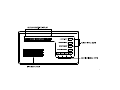
Fire System
User’s Guide
Table of Contents
Introduction
Command Center Function Keys
Viewing System Events
Warning Displays and Tones
Fire Alarms
Silencing Fire Troubles
Detector Reset Key
Annunciator Reset Key
The Idle Display
How the System Reports Alarms
System Functions
View Memory
Fire Test
View Log
Remote Program
System Trouble Displays
Log Event Definitions
System Glossary
Maintenance and Service
3
4
5
5
6
7
8
9
10
11
12
13
14
16
17
21
23
26
27
1
2
Introduction
Using the Command Center
Your system’s command center is an advanced digital device that
offers a variety of features. Its highly visible, back-lit keypad and
built-in sounder alert you to a number of system events.
Your system provides access to functions through the Menu. Access
the Menu by pressing the [ESC] key. Pressing the [PREV] or
[NEXT] key allows you to scroll up or down through the list of
functions programmed by your security company. Pressing the
[ENT] key initiates the function displayed. To exit the Menu, press
the [ESC] key.
About This User’s Guide
This User’s Guide covers basic system features. It is designed to be
an everyday type of reference for system users. The functions
described in this guide are programmed by your security company.
Some of them may not be included in your system.
Throughout this guide the # symbol refers to a variable numerical
quantity, such as the number of points to test. Messages that
appear in the command center display appear in this guide LIKE
THIS. Keys that you must press appear [LIKE THIS].
What is a Point?
A “point” is a detection device, or group of devices connected to
your system. Points display individually at the command center
with custom text. The text can describe a single smoke detector, or
an area such as FIRST FLOOR or LOBBY.
3
Command Center Function Keys
ENT (Enter)
Your command center has four function keys. These keys are used
to control your system.
The function of the [ENT] key is to select the menu item displayed.
Command Center Quiets for Keystrokes
ESC (Escape)
The [ESC] key has two functions. First, the [ESC] key is used to
enter the Menu. Pressing this key takes you to the first item in the
menu.
Pressing [ESC], [PREV], [NEXT], or [ENT] lights the keys and
quiets any warning tones. If you don’t press another key within 20
seconds, the keypad lights go out and the warning tones resume.
Second, pressing [ESC] takes you back to the idle display.
PREV (Previous)
When viewing a list, pressing the [PREV] key takes you back to the
previously shown item.
NEXT
Press the [NEXT] key to view the next item in a menu or list.
4
Viewing System Events
Warning Displays and Tones
Your system automatically displays fire alarm events or fire trouble
events as they occur. Fire trouble events include such things as a
broken wire or a closed sprinkler system valve.
Your command center emits one of several distinct tones and
displays custom text to alert you to system events. Additional bells
or horns may also be connected to your system. Audible and visual
devices such as horns and strobes alert you to emergencies.
Priority of Events
If more than one event occurs, your system sorts them into one of
three groups. The groups (highest priority first) are: Fire Alarms,
Fire Troubles, and Non-Fire Troubles.
The group with the highest priority scrolls first in the command
center’s display. Descriptions of the tones and displays for each
group and instructions for silencing the tones are included in the
descriptions that follow.
5
Fire Alarms
Alarm Silence Key
Fire alarms are the highest priority events. When a fire point
activates, your command center emits a pulsating high-pitched fire
tone. Evacuate all occupants and investigate for smoke or fire. The
tone sounds for the time set by your servicing company.
Press the [ALARM SILENCE] key to silence a fire alarm. After
pressing [ALARM SILENCE], the system briefly displays * FIRE
SYSTEM * followed by ALARM SILENCED and then the
number of fire points in alarm (A1 ## FIRE ALARM) in the
area and then the custom text of all the points in alarm in the order
of occurrence. Your system may be programmed so that you
cannot silence some fire alarms until the fire event is cleared. The
example below illustrates the displays one would see with two
points in alarm. See the description of the Detector Reset key and
the Annunciator Reset key for more information.
The command center display shows only the point text of the first
point that went into fire alarm. Pressing the [NEXT] manually
displays additional points (if any) that went into alarm. Events
scroll from the oldest to the newest.
* FIRE SYSTEM *
ALARM SILENCED
A1 2 FIRE ALARM
LOBBY SMOKE
1ST FLOOR
6
Silencing Fire Troubles
Special System Trouble Display
After an alarm is silenced, the device that caused the alarm is usually
still faulted or activated. In the case of a smoke detector, it must be
reset by pressing the [DETECTOR RESET] button (see page 8). An
off-normal device creates a fire trouble condition. Examples of
trouble conditions include such things as a closed valve or broken
wire. When a fire trouble occurs, your command center emits three
warble tones, then a pause (repeatedly).
SERVC AC FAIL and SERVC BATT LOW are examples of
special system trouble displays. These displays appear on all
keypads in the system. These trouble displays begin with SERVC.
See System Trouble Displays on page 21 for a description of each
system trouble display. Pressing the [TROUBLE SILENCE] key will
silence a system trouble tone, but the SERVC display will not clear
until the faulted condition is corrected.
The system displays the number of fire points with troubles (A1
## FIRE TRBLE) in an area and then repeatedly displays the
custom text for all the points in trouble in the order of occurrence.
Trouble Silence Key
Pressing the [TROUBLE SILENCE] key silences a fire trouble. If the
fault condition is still present, the display will repeatedly scroll from
* FIRE SYSTEM * to FIRE TROUBLE. Manually press the
[NEXT] key repeatedly to display all of the devices that are still off
normal. When all devices return to normal, the FIRE TROUBLE
display automatically clears. If you wish to review cleared troubles,
this can be done by pressing the [ESC] key to enter the Menu and
then pressing [NEXT] until VIEW MEMORY ? is displayed. See
the VIEW MEMORY ? function on page 13 for more
information.
7
Detector Reset Key
Description
Detection devices, such as smoke detectors, must be reset after being
activated. Pressing the [DETECTOR RESET] key momentarily
removes power from these sensors to reset them.
Detector Reset Key
If the fault condition is still present, the display repeatedly scrolls
from * FIRE SYSTEM * to FIRE TROUBLE. Manually
press the [NEXT] key repeatedly to display all of the devices that are
still off-normal. When all devices return to normal the FIRE
TROUBLE display automatically clears. Check to be certain that
there is no smoke, fire, or other danger present.
If you can’t reset the detector or sensor contact your service
company.
After pressing this key, the display shows SENSORS RESETING
for approximately 3 seconds and then goes blank before returning
to the repeated display of * FIRE SYSTEM * followed by
ALARM SILENCED. This function clears alarm point information
from the display. The ALARM SILENCED message continues to
display as a reminder that the VIEW MEMORY ? function can still
be used to view cleared point information. Pressing the
[ANNUNCIATOR RESET] key clears both the View Memory
buffer and the ALARM SILENCED display. For more information
see the description of the VIEW MEMORY ? function (page 13).
8
Annunciator Reset Key
Description
After the [ALARM SILENCE], [TROUBLE SILENCE] and/or
[DETECTOR RESET] keys are pressed, retrieve the cleared keypad
display information with the View Memory ? menu function.
Pressing the [ANNUNCIATOR RESET] key clears the ALARM
SILENCED message from the display and clears the VIEW
MEMORY ? buffer and returns the display to idle text.
Thereafter the VIEW MEMORY ? function displays NO EVENTS
until another trouble or alarm occurs. Using [ANNUNCIATOR
RESET] has no effect on the VIEW LOG ? function. See the VIEW
MEMORY ? and VIEW LOG ? functions for more information.
9
The Idle Display
“At an idle state” means that the system is not currently performing a function entered by a user.
• PRESS ALARM SIL
Indicates that the [ALARM SILENCE] key needs to be pressed.
• * FIRE SYSTEM *
This is the normal idle display that indicates the system is normal and ready to function.
• CHECK FIRE SYS
This is one of a number of displays that indicate the system requires service.
This guide uses the default idle state displays for examples of these idle states. Your security company may have programmed custom text
for the idle displays in your system.
10
Keystroke Checking Tones
How the System Reports Alarms
Valid Entry
Your system may be programmed to automatically send reports to
your monitoring facility. This communication temporarily
disconnects your telephones. Once the report is completed, your
system returns the telephones to normal operation (check with
your servicing company).
If you press an appropriate key for the function or entry you desire,
the command center sounds a muted beep tone, indicating it
accepted your keystroke.
Invalid Entry
A flat buzz tone sounds when you press a key that doesn’t have a
function to execute or when the command center has no
information to display.
Your system makes repeated attempts to send reports to your
monitoring facility. In the event your system fails to communicate,
the command center buzzes and displays SERVC COMM FAIL.
Notify your servicing company of the communications failure.
Note: If your telephone service is interrupted, your system cannot
send reports unless it has an alternate means of transmitting them.
11
System Functions
Below is a summary of the features covered in this guide. Some of these functions may not be available in your menu. Access the menu by
pressing the [ESC] key. The first menu item, ALARM SILENCE ?, is displayed. This function can be selected by pressing the [ENT] key.
Doing this has the same effect as pressing the [ALARM SILENCE] key.
Pressing the [NEXT] key when ALARM SILENCE ? is displayed brings up the second menu item, which is TROUBLE SILENCE ?.
Pressing [NEXT] again displays the third item in the menu, DETECTOR RESET ?. Pressing [NEXT] once more displays the fourth
menu item, ANNUNCATOR RESET ?. These menu items perform the same functions as the first four keys on the command center.
Continue pressing the [NEXT] key to access special menu items that might be programmed into your system by your servicing company.
Pressing the [ENT] key while one of these items is displayed performs that function. Each of these functions is described in the following
pages:
Menu Item
1
2
3
4
5
6
7
8
9
10
Function
ALARM SILENCE
TROUBLE SILENCE
DETECTOR RESET
ANNUNCIATOR RESET
VIEW MEMORY
FIRE TEST
VIEW LOG
REMOTE PROGRAM
DISPLAY REV
VIEW PT STATUS
12
VIEW MEMORY?
View Event Memory
Using View Memory:
1.
Press the [ESC] key to enter the menu, then press [NEXT]
repeatedly until you reach the VIEW MEMORY ? prompt.
Press [ENT].
2.
Your system displays event summary lines and point text in this
order: fire alarm summary line, point text for each fire alarm
event; fire trouble summary line, point text for each fire trouble
event; trouble summary line, and point text for each trouble
event. Press [NEXT] to scroll through the events. If there are no
events to view, NO EVENTS displays.
3.
Return to idle text at any time by pressing [ESC].
Description
Event memory allows you or a service technician to review events after
they are cleared from the command center’s display. Use this function to
view event memory.
Your system stores events that have occurred since the last time
[ANNUNCIATOR RESET] was pressed. Each time you press the
[ANNUNCIATOR RESET] key, the ALARM SILENCED message
clears from the display and the Event Memory is erased and new events
are recorded as they occur.
13
FIRE TEST ?
Using Fire Test:
Description
1.
Use this function to test fire points to be certain they function
properly. You can review untested points at your command center
to help locate the remaining detectors to be tested.
Press the [ESC] key to enter the menu, then press [NEXT]
repeatedly until you reach the FIRE TEST ? prompt.
Press [ENT].
2.
The display shows ## PTS TO TEST.
3.
One-at-a-time, activate the detection devices to fault each
point.
4.
As you fault each point, your command center displays the
point text for 60 seconds and the bell will sound for 2
seconds. This verifies that the detection device is working
properly. Your system automatically resets smoke
detectors.
Upon initiation, the fire test will test the fire pattern on the alarm
output and ring the command center sounder for 2 seconds. The
AC is disabled for 4 minutes in order to test the system’s battery
power. If the battery cannot maintain the system for the 4 minute
period, the command center appears to go dead. If this happens,
contact your servicing company. At the end of the 4 minute period,
AC is returned to the system and the panel restores. A message is
sent to your monitoring facility upon initiation and completion of
the Fire Test. During the Fire Test, no alarms are sent to your
monitoring facility.
If there is no activity on the system for 20 minutes, the system
automatically exits from the Fire Test.
When a resettable point (such as a smoke detector) is
faulted, the display shows SENSOR RESETTING for 5
seconds. During this time power is removed from smoke
power relays.
14
FIRE TEST ? (continued)
Faulting a point more than once does not increment the test
count. However, the command center emits a brief tone and
displays the point text each time you fault the point,
allowing you to test multiple devices assigned to one point.
5.
When all points have been tested, 0 PTS TO TEST is
displayed. Press [ESC]. The display momentarily shows
ALL PTS TESTED before returning to idle text.
6.
During the Fire Test you may want to see the points that
remain untested. Press the [ESC] key and VIEW
UNTESTED ? is displayed. Press [ENT]. The display
shows # PTS UNTESTED. Press [NEXT] to see a list of
the points that were not yet tested. Move through this list
by pressing the [NEXT] key. To resume the Fire Test, press
[ESC]. ## PTS TO TEST is displayed.
Automatic time-out returns the system to idle text: If there is no
point or command center activity for 20 minutes, the fire test ends
automatically. The command center returns to idle text.
Press [ESC] twice to leave the Fire Test mode.
15
VIEW LOG ?
2.
To view the entire log from the newest event, press [ENT].
Description
The date and time of the event displays. Press [NEXT] to
view the description of the event, or press [PREV] to view
the description of the prior event. Press [PREV] again to
view the date and time of the previous event.
Use this function to review events in your system at your command
center. Reviewing past events may help you identify problems.
Viewing events does not require any additional equipment since the
information is displayed at your command center. Events are
stored in the panel’s memory in order of occurrence and tagged
with the date and time.
Continue to press [PREV] to view event descriptions and
the date and time of each event.
See the Log Event Definitions section on page 21 for more
information regarding logged events.
Note: When using the [NEXT] key to view the log, the date
and time of the event are displayed first, followed by the
description of the event. An event description may take up
two displays.
Using View Log:
1.
Press the [ESC] key to enter the Menu, then press [NEXT]
repeatedly until you reach the VIEW LOG ? prompt.
Press [ENT].
ENTER START DATE displays.
3.
Continue pressing [NEXT] to view the rest of the log. When
you reach the end of the log, END OF LOG displays.
4.
Press [ESC] to return to idle text.
16
REMOTE PROGRAM ?
For systems without a phone number:
1.
Ensure your security system is at idle text.
2.
Call this phone number: ______________________.
This number is designated for the Remote Account
Manager. You must make the call using the telephone
located ___________________________.
3.
Identify yourself and your premises (account number,
name, address, etc.) and advise the operator of the services
you wish to have performed.
4.
Press the [ESC] key to enter the Menu, then press [NEXT]
repeatedly until you reach the REMOTE PROGRAM ?
prompt. Press [ENT].
My system has a phone number.
5.
The display shows RAM CONNECTING.
My system does not have a phone number.
6.
The security system now disconnects telephones sharing its
telephone line during the remote programming session.
Hang up the telephone now.
7.
The display changes to SYSTEM PROGRAM.
Description
Your servicing company can remotely program your security
system using the telephone line your panel is connected to.
Your servicing company may ask you to follow the steps below to
begin a remote programming session. The time it takes to program
the panel is dependent on the number of changes made to the
program.
You’ll notice that two sets of procedures are presented. Which one
you use depends upon whether your system has a preprogrammed telephone number in its memory.
17
8.
At the conclusion of the programming session your system
sends a report to the security company and then returns
your telephone to normal service and your display to idle
text.
For systems with a phone number:
1.
Ensure your security system is at idle text.
2.
Call this phone number: ______________________.
This number is designated for the Remote Account
Manager.
3.
Identify yourself and your premises (account number,
name, address, etc.) and advise the operator of the services
you wish to have performed.
4.
Press the [ESC] key to enter the Menu, then press [NEXT]
repeatedly until you reach the REMOTE PROGRAM ?
prompt. Press [ENT].
5.
The display shows CALL RAM ?
Note: The central station may direct you to press [NEXT].
When you do this, ANSWER NOW displays. Press [ENT]
and the system will behave as described in previous steps 5
through 8.
• If you want your system to call the RAM, press [ENT]
when the display shows CALL RAM ?.The display shows
CALLING RAM momentarily as the panel dials the RAM
phone number in its memory. The display changes to
SYSTEM PROGRAM when it has connected to RAM.
6.
At the conclusion of the programming session your system
sends a report to the security company and then returns
your telephone to normal service and your display to idle
text.
18
VIEW POINT STATUS ?
• PT###_OPEN_HW: a HW point is open.
Description
• PT###_NORML_HW: a HW point is normal.
Use this function to identify the number or location of each point
in an area, and to show the current condition of any point you
select. This function is useful as an aid in servicing the system.
1.
Press the [ESC] key to enter the Menu. Press [NEXT]
until the VIEW PT STATUS ? function is displayed.
2.
Press [ENT]. The display shows AREA X ## (where X
= the area number and ## = the number of points to
view).
3.
Press [ENT]. The display shows PT ## XXXXX (where
XXXXX = the type of point). Press [ENT] again to see the
current condition of the point. The display shows one of
the following:
• PT###_SHORT_HW: a hard wire (HW) point is
shorted.
• PT###_MISNG_HW: a HW point is missing.
4.
Continue to press [ENT] to see the type and condition of
each point in the area.
5.
Press [ESC] to return to idle text.
DISPLAY REV?
Description
This function displays the revision of firmware currently installed in
the panel.
1.
Press the [ESC] key to enter the Menu. Press [NEXT] until
the DISPLAY REV ? function is displayed.
2.
The current revision of firmware displays
(9112 REV # # - # #) for 5 seconds.
3.
The display returns to idle text.
20
System Trouble Displays
If you see any of the following system trouble displays, contact
your servicing company to determine whether repairs are needed:
SERVC BATT LOW
Indicates the system’s battery is low, or temporarily draining faster
than the system can charge it. If this display remains or appears
frequently, call your security company for service.
CALL FOR SERVICE
Call your servicing company. Your security system may have failed.
SERVC BATT MSING
Indicates the system’s battery is disconnected or shorted.
SERVC PANEL
Indicates a problem with the panel. The panel is not operating. Call
your servicing company for service.
SERVC COMM FAIL
Your system makes repeated attempts to communicate with the
monitoring facility. In the event your system fails to communicate,
the command center buzzes and displays SERVC COMM FAIL.
Notify your servicing company of the communication trouble. This
message may not appear in some systems.
SERVC PARAM
Indicates a problem with the panel. Your panel may not be
operating properly. Call your servicing company for service.
SERVC AC FAIL
Indicates that AC power to the system is interrupted. Check the
plug-in transformer and circuit breaker. Pressing [TROUBLE
SILENCE] silences the trouble buzz. The display clears when AC
power returns.
SERVC KEYPAD
Indicates that a command center, other than the one displaying the
message, is in a trouble condition. Notify your servicing company.
21
SERVC PH LINE #1 (or 2)
Indicates telephone line trouble. Call your phone company from
another phone to report telephone trouble. This message may not
appear in some systems.
ALARM SILENCED
This display is added to the scrolling alarm display when alarm
sounders are silenced. This message clears when the
[ANNUNCIATOR RESET] key is pressed.
SERVC PRINTER
Indicates that a local printer (if installed) at your premises is in a
trouble condition. Check to be sure the printer is powered on, the
paper is correctly inserted, and the printer is selected. Contact your
servicing company if you have questions, or the display doesn’t
clear. You system may not include a local printer.
FIRE BYPASS
This display is scrolled when a fire point has been removed from
the system via the keypad using the BYPASS A POINT ?
function.
SERVC PT BUS #
Displays when a problem occurs with one of the panel’s circuits.
Call your security company.
FIRST DISARM
Indicates that the function requested can only be performed when the
idle display shows * FIRE SYSTEM *. Press the [ALARM
SILENCE] key.
22
Log Event Definitions
BYPASS - Point bypassed. An event modifier showing how the
point was bypassed follows this event in the log.
AC FAIL - AC power to the panel interrupted.
CANCEL - User canceled an alarm from the area specified.
AC RSTOR - AC power to the panel restored.
CKSUM FAIL - Panel programming corrupted. Call for service.
ALARM - Alarm at point in area specified.
AUTO - Event Modifier for BYPASS event. Indicates four alarms
or troubles in one clock hour caused automatic (swinger) bypass.
BAD CALL - System tried to call Remote Account Manager and
failed.
COMM FAIL - Panel could not communicate using phone line
reported.
COMM RSTOR - The communication problem with the phone line
indicated resolved.
DATE CHG - User changed panel’s date and/or time.
BATT LOW - Panel battery is below 11.7 VDC.
EXTRA PT - Incorrectly programmed point connected to system.
BATT MISS - Panel battery disconnected or discharged.
FIRE ALARM - Fire alarm at point in area specified.
BATT RSTOR - Panel battery recharged.
FIRE END - Fire Walk Test ended.
BUS RSTOR - Data Expansion Loop for off-board points
restored.
FIRE RSTOR - Fire alarm at point specified restored.
BUS TRBLE - Data Expansion Loop for off-board points faulted.
23
FIRE TRBLE - Trouble condition at point specified.
PROG OK - Panel successfully programmed by a local programmer.
FIRE START - Fire Walk Test started.
PT TESTED - This point walk tested.
LOG FULL - Panel log is full. New event overwrites oldest event.
PWR RESET - Power was reset at specified time.
LOG THRES - Panel log reached programmed threshold (Log %
Full).
RAM FAIL - RAM programming session terminated abnormally or
RAM using incorrect passcode and/or lock code.
MISS FIRE - Fire point specified missing.
RAM OK - RAM programming session terminated normally.
MISS TRBLE - Point in area specified missing. Area disarmed.
REBOOT - Panel reset.
PARAM CHG - Panel programming changed.
RELAY SET - Relay set (activated). An event modifier showing how
the relay was set follows this event in the log.
PHONE FAIL - Panel detected phone line specified as faulted.
PHONERESTOR - Phone line specified detected as restored from
faulted condition.
PROG - Event modifier for BYPASS, RELAY SET, and RELY RESET
events. Indicates function initiated from local programmer.
RELY RESET - Relay reset (deactivated). An event modifier showing
how the relay was reset follows this event in the log.
REMO - Event modifier for BYPASS, RELAY SET, and RELY RESET
events. Indicates function initiated from Remote Account Manager
(RAM).
PROG BAD - Attempt to access panel with a local programmer failed.
24
REMO RESET - Panel reset from RAM.
STAT RPT - Status report sent.
RESTORAL - Restoral at device in area specified.
TEST RPT - Test report sent.
SDI FAIL - SDI device specified is not working. 1 to 8 =
supervised command centers, 017, 018, 019 = printers.
TIME CHG - User changed panel’s time.
TROUBLE - Trouble condition at point specified.
SDI RSTOR - The problem with SDI device specified resolved.
WALK END - Walk test in area specified completed.
SENSOR - Event modifier for SENS RESET event. Shows the relay
number activated for reset.
SENS RESET - User reset area sensor in area specified. An event
modifier showing the relay number activated for reset follows this
event.
WALK STRT - Walk test initiated in specified area.
WATCHDOG - Panel’s normal CPU operation interrupted and restarted.
Call for service if event occurs regularly or frequently.
SKD CHG - User changed time for Sked specified to be executed.
SKD XEQ - Sked executed.
SKED - Event modifier for BYPASS, RELAY SET, and RELY RESET
events. Indicates function initiated by a SKED (scheduled event).
25
System Glossary
Area - A group of detection devices connected to your security
system.
Monitoring Facility - A facility where trained personnel
monitor your system 24 hours a day. Your system may be
programmed to contact this facility during alarm conditions,
enabling personnel to dispatch the proper authorities.
Relay - Your system may have relays programmed to provide
control of devices such as premises lighting or entry gates.
Your security company programs relays for automatic control
and/or control from your command center.
Trouble - A service condition that needs to be corrected, such
as a broken wire.
Menu - A list of functions programmed by your servicing
company.
Faulted Point - A point that is not normal.
Idle Text - The system displays idle text at command centers
when it is not performing a user requested function. Idle text
shows the status of the system.
Point - A detection device, or group of devices connected to
your system. Points display individually at the command center
with custom text. The text can describe a single smoke detector,
or an area such as UPSTAIRS or GARAGE.
26
Maintenance and Service
This system requires very little maintenance, however, you should
test the system weekly to ensure it is working properly. A test
schedule and maintenance program can be arranged. If you notice a
change in operation during normal use or testing, call for service as
soon as possible. Do not attempt to repair the control panel,
command centers, or detectors yourself.
How to Clean the Command Center
If your command center gets dirty, apply a
household glass cleaner to a clean cloth or paper
towel and wipe the surface. Do not spray any
liquid directly onto the command center. It could
run inside the case and damage electrical circuits.
How to Clean the Command Center
If your command center gets dirty, apply a household glass cleaner
to a clean cloth or paper towel and wipe the surface. Do not spray
any liquid directly onto the command center. It could run inside the
case and damage electrical circuits.
71-06991-000-D 03/03
D1256