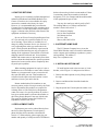
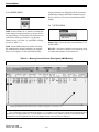
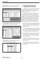
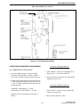
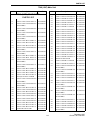
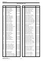
1
751x (VHF)
754x (UHF)
CONVENTIONAL
TWO-WAY RADIO
VHF 136-150 and 146-174 MHz
1 and 5 Watts, 9.6 VDC
UHF 400-430, 440-470, 470-500, and 490-512 MHz
1 and 4 Watts, 9.6 VDC
Copyright ©1999 by the E.F. Johnson Company
E.F. Johnson Company, which was founded in 1923, designs, manufactures, and markets
radio communication products, systems, and services worldwide. E.F. Johnson produces
equipment for land mobile radio and mobiletelephone services which include business,
industrial, government, public safety, and personal users.
Viking Head/EFJohnson® logo and Call Guard® are registered trademarks of the E.F.
Johnson Company. Smartrunk II™ is a trademark of Smartrunk Systems Inc. All other
company and/or product names used in this manual are trademarks and/or registered
trademarks of their respective manufacturer.
Information in this manual is subject to change without notice.
Revised July 1999
Part No. 001-7500-002
TABLE OF CONTENTS
1
GENERAL INFORMATION
1.1
1.2
1.3
1.4
1.5
1.6
1.7
1.8
1.9
1.10
1.11
1.12
SCOPE OF MANUAL . . . . . . . . . . . . . . . . . . . .1-1
TRANSCEIVER DESCRIPTION . . . . . . . . . . .1-1
PART NUMBER BREAKDOWN . . . . . . . . . . .1-1
TRANSCEIVER IDENTIFICATION. . . . . . . . .1-1
ACCESSORIES . . . . . . . . . . . . . . . . . . . . . . . . .1-1
PRODUCT WARRANTY . . . . . . . . . . . . . . . . .1-1
FACTORY CUSTOMER SERVICE. . . . . . . . .1-2
FACTORY RETURNS. . . . . . . . . . . . . . . . . . . .1-3
REPLACEMENT PARTS . . . . . . . . . . . . . . . . .1-3
INTERNET HOME PAGE . . . . . . . . . . . . . . . . .1-3
INSTALLING OPTION UNIT . . . . . . . . . . . . . .1-3
TWO-TONE DECODER SETUP . . . . . . . . . . .1-4
Installation and Programming. . . . . . . . . . . . . . . 1-4
Setting Tone Frequencies . . . . . . . . . . . . . . . . . . 1-4
1.13 FIVE-TONE ENCODER/DECODER SETUP.1-5
Installation and Programming. . . . . . . . . . . . . . . 1-5
Setting 5-Tone Deviation . . . . . . . . . . . . . . . . . . 1-5
1.14 RADIO DISASSEMBLY PROCEDURE . . . . .1-6
Removing Chassis. . . . . . . . . . . . . . . . . . . . . . . . 1-6
Removing Main Unit From Chassis . . . . . . . . . . 1-6
1.15 REVISION SUMMARY . . . . . . . . . . . . . . . . . . .1-7
General . . . . . . . . . . . . . . . . . . . . . . . . . . . . . . . . 1-7
Software Revisions . . . . . . . . . . . . . . . . . . . . . . . 1-7
VHF (7510) Hardware Revisions . . . . . . . . . . . 1-7
UHF (7540) Hardware Revisions . . . . . . . . . . . 1-7
SPECIFICATIONS . . . . . . . . . . . . . . . . . . . . . . .1-8
2
TRANSCEIVER OPERATION
2.1
2.2
2.3
TRANSCEIVER FEATURES . . . . . . . . . . . . . .2-1
CONTROLS AND DISPLAY . . . . . . . . . . . . . .2-1
GETTING STARTED. . . . . . . . . . . . . . . . . . . . .2-2
Unpacking . . . . . . . . . . . . . . . . . . . . . . . . . . . . . . 2-2
Antenna . . . . . . . . . . . . . . . . . . . . . . . . . . . . . . . . 2-2
Belt Clip . . . . . . . . . . . . . . . . . . . . . . . . . . . . . . . 2-2
Turning Power On. . . . . . . . . . . . . . . . . . . . . . . . 2-2
Changing Channel. . . . . . . . . . . . . . . . . . . . . . . . 2-2
Adjusting Volume. . . . . . . . . . . . . . . . . . . . . . . . 2-3
BASIC OPERATION . . . . . . . . . . . . . . . . . . . . .2-3
Receiving a Call . . . . . . . . . . . . . . . . . . . . . . . . . 2-3
Transmitting a Call . . . . . . . . . . . . . . . . . . . . . . . 2-3
Low Battery Indication . . . . . . . . . . . . . . . . . . . . 2-3
Time-Out Timer . . . . . . . . . . . . . . . . . . . . . . . . . 2-3
Selective Calling . . . . . . . . . . . . . . . . . . . . . . . . . 2-3
PROGRAMMABLE FUNCTIONS . . . . . . . . . .2-4
General . . . . . . . . . . . . . . . . . . . . . . . . . . . . . . . . 2-4
Keypad Lock . . . . . . . . . . . . . . . . . . . . . . . . . . . . 2-4
Priority Channel . . . . . . . . . . . . . . . . . . . . . . . . . 2-4
2.4
2.5
Revised July 1999
Part No. 001-7500-002
2.6
Scan . . . . . . . . . . . . . . . . . . . . . . . . . . . . . . . . . . .
Key Beep . . . . . . . . . . . . . . . . . . . . . . . . . . . . . . .
Monitor . . . . . . . . . . . . . . . . . . . . . . . . . . . . . . . .
Talk-Around . . . . . . . . . . . . . . . . . . . . . . . . . . . .
DTMF Transmission . . . . . . . . . . . . . . . . . . . . . .
DTMF Redial . . . . . . . . . . . . . . . . . . . . . . . . . . .
High/Low Power Output . . . . . . . . . . . . . . . . . . .
Emergency Operation . . . . . . . . . . . . . . . . . . . . .
Display Lighting . . . . . . . . . . . . . . . . . . . . . . . . .
BATTERY INFORMATION. . . . . . . . . . . . . . .
Battery Pack Replacement . . . . . . . . . . . . . . . . .
Miscellaneous Battery Information . . . . . . . . . . .
Using Battery Case . . . . . . . . . . . . . . . . . . . . . . .
Battery Charging Information . . . . . . . . . . . . . . .
Using Desktop Charger . . . . . . . . . . . . . . . . . . . .
Using Multi-unit Charger . . . . . . . . . . . . . . . . . .
Using Wall Charger. . . . . . . . . . . . . . . . . . . . . . .
Using Optional Cables . . . . . . . . . . . . . . . . . . . .
Replacement Battery Pack . . . . . . . . . . . . . . . . .
3
PROGRAMMING
3.1
GENERAL . . . . . . . . . . . . . . . . . . . . . . . . . . . . . 3-1
Programming Setup. . . . . . . . . . . . . . . . . . . . . . . 3-1
Programming Cable. . . . . . . . . . . . . . . . . . . . . . . 3-1
Programming Software . . . . . . . . . . . . . . . . . . . . 3-1
Software Version Required . . . . . . . . . . . . . . . . . 3-2
STARTING THE PROGRAM . . . . . . . . . . . . . 3-2
SPECIAL KEYS AND FUNCTIONS . . . . . . . 3-2
MENU FLOW . . . . . . . . . . . . . . . . . . . . . . . . . . 3-2
Introduction . . . . . . . . . . . . . . . . . . . . . . . . . . . . . 3-2
File Menu . . . . . . . . . . . . . . . . . . . . . . . . . . . . . . 3-2
Screen Menu . . . . . . . . . . . . . . . . . . . . . . . . . . . . 3-3
Program Menu. . . . . . . . . . . . . . . . . . . . . . . . . . . 3-3
Print Menu. . . . . . . . . . . . . . . . . . . . . . . . . . . . . . 3-3
Model Menu . . . . . . . . . . . . . . . . . . . . . . . . . . . . 3-4
Setup menu . . . . . . . . . . . . . . . . . . . . . . . . . . . . . 3-4
UNIQUE PMR (EUROPEAN) SCREENS . 3-14
General . . . . . . . . . . . . . . . . . . . . . . . . . . . . . . . 3-14
Unique PMR Screens . . . . . . . . . . . . . . . . . . . . 3-14
CLONING (PROGRAMMING ONE
TRANSCEIVER WITH ANOTHER) . . . . . 3-16
3.2
3.3
3.4
3.5
3.6
ii
2-4
2-4
2-4
2-5
2-5
2-5
2-5
2-5
2-5
2-5
2-5
2-6
2-6
2-6
2-7
2-7
2-7
2-8
2-8
4
CIRCUIT DESCRIPTION
4.1
RECEIVER CIRCUIT . . . . . . . . . . . . . . . . . . . . 4-1
Antenna Switching Circuit . . . . . . . . . . . . . . . . . 4-1
RF Circuit . . . . . . . . . . . . . . . . . . . . . . . . . . . . . . 4-1
TABLE OF CONTENTS (CONT’D)
4.2
4.3
4.4
4.5
4.6
5
ADJUSTMENT PROCEDURE
5.1
GENERAL. . . . . . . . . . . . . . . . . . . . . . . . . . . . . . 5-1
Required Test Equipment . . . . . . . . . . . . . . . . . . 5-1
Test Channels and Power Select. . . . . . . . . . . . . 5-2
Computer-Aided Tuning . . . . . . . . . . . . . . . . . . 5-2
Reprogramming if EEPROM is Replaced or
Error Occurs . . . . . . . . . . . . . . . . . . . . . . . . . 5-3
PRELIMINARY SETUP . . . . . . . . . . . . . . . . . . 5-3
5.2
UHF MODELS
First Mixer and First IF Circuit . . . . . . . . . . . . . 4-1
Second IF and Demodulator Circuits . . . . . . . . . 4-1
AF Circuit . . . . . . . . . . . . . . . . . . . . . . . . . . . . . . 4-2
Squelch Circuit . . . . . . . . . . . . . . . . . . . . . . . . . . 4-2
TRANSMITTER CIRCUITS . . . . . . . . . . . . . . . 4-2
Microphone Amplifier Circuit . . . . . . . . . . . . . . 4-2
Modulation Circuit . . . . . . . . . . . . . . . . . . . . . . . 4-2
Drive/Power Amplifier Circuits . . . . . . . . . . . . . 4-3
Current Detector Circuit . . . . . . . . . . . . . . . . . . . 4-3
Power Detector (UHF Only). . . . . . . . . . . . . . . . 4-3
APC Circuit . . . . . . . . . . . . . . . . . . . . . . . . . . . . 4-3
PLL CIRCUIT . . . . . . . . . . . . . . . . . . . . . . . . . . . 4-4
POWER SUPPLY CIRCUITS . . . . . . . . . . . . . 4-4
CPU PORT ALLOCATION . . . . . . . . . . . . . . . 4-5
OUTPUT EXPANDER IC10
ALLOCATIONS . . . . . . . . . . . . . . . . . . . . . . . 4-5
5.6
5.7
5.8
6
5.5
PARTS LIST
VHF Main Unit Parts List. . . . . . . . . . . . . . . . . . .6-1
UHF Main Unit Parts List. . . . . . . . . . . . . . . . . . .6-9
VHF/UHF Chassis Parts . . . . . . . . . . . . . . . . . . .6-18
VHF/UHF Exploded View . . . . . . . . . . . . . . . . .6-19
Transistor and Diode Basing. . . . . . . . . . . . . . . .6-20
7
SCHEMATIC DIAGRAMS AND
COMPONENT LAYOUTS
7510 (VHF) MAIN UNIT
VHF MODELS
5.3
5.4
PLL ADJUSTMENT (UHF MODELS) . . . . . .5-7
TRANSMITTER ADJUSTMENTS (UHF
MODELS) . . . . . . . . . . . . . . . . . . . . . . . . . . . . .5-7
Reference Frequency . . . . . . . . . . . . . . . . . . . . . 5-7
Output Power Adjust. . . . . . . . . . . . . . . . . . . . . . 5-8
FM Deviation Adjust . . . . . . . . . . . . . . . . . . . . . 5-8
DTCS Waveform Adjust. . . . . . . . . . . . . . . . . . . 5-8
RECEIVER ADJUSTMENTS
(UHF MODELS). . . . . . . . . . . . . . . . . . . . . . . .5-9
Bandpass Filter Adjust . . . . . . . . . . . . . . . . . . . . 5-9
Squelch Adjust . . . . . . . . . . . . . . . . . . . . . . . . . 5-10
Block Diagram . . . . . . . . . . . . . . . . . . . . . . . . . .7-1
Major Component Location Diagrams . . . . . . .7-7
PC Board Top View. . . . . . . . . . . . . . . . . . . . . .7-3
PC Board Bottom View . . . . . . . . . . . . . . . . . . .7-4
Schematic Diagram . . . . . . . . . . . . . . . . . . 7-8/7-9
PLL ADJUSTMENT (VHF MODELS) . . . . . . 5-4
TRANSMITTER ADJUSTMENTS
(VHF MODELS) . . . . . . . . . . . . . . . . . . . . . . . 5-4
Reference Frequency . . . . . . . . . . . . . . . . . . . . . 5-4
Output Power Adjust . . . . . . . . . . . . . . . . . . . . . 5-5
FM Deviation Adjust . . . . . . . . . . . . . . . . . . . . . 5-5
DTCS Waveform Adjust . . . . . . . . . . . . . . . . . . .5-5
RECEIVER ADJUSTMENTS
(VHF MODELS) . . . . . . . . . . . . . . . . . . . . . . . 5-5
Bandpass Filter Adjust . . . . . . . . . . . . . . . . . . . . 5-5
Squelch Adjust . . . . . . . . . . . . . . . . . . . . . . . . . . . 5-6
7540 (UHF) MAIN UNIT
Block Diagram . . . . . . . . . . . . . . . . . . . . . . . . . .7-2
Major Component Location Diagrams . . . . . .7-12
PC Board Top View. . . . . . . . . . . . . . . . . . . . . .7-5
PC Board Bottom View . . . . . . . . . . . . . . . . . . .7-6
Schematic Diagram . . . . . . . . . . . . . . . . 7-10/7-11
iii
Revised July 1999
Part No. 001-7500-002
TABLE OF CONTENTS (CONT’D)
LIST OF FIGURES
1-1
1-2
1-3
1-4
3-1
3-2
4-1
4-2
4-3
5-1
5-2
5-3
5-4
5-5
7-1
7-2
LIST OF TABLES
Option Unit Installation . . . . . . . . . . . . . . . . . . . 1-3
Two-Tone Decoder Adjustment Points . . . . . . . 1-4
Chassis Removal. . . . . . . . . . . . . . . . . . . . . . . . . 1-6
Main Unit Removal From Chassis . . . . . . . . . . . 1-6
Programming Setup . . . . . . . . . . . . . . . . . . . . . . 3-1
Memory Channel Screen (PMR Models) . . . . . 3-15
Second IF and Demodulator Circuits . . . . . . . . . 4-2
APC Circuit. . . . . . . . . . . . . . . . . . . . . . . . . . . . . 4-3
PLL Circuit . . . . . . . . . . . . . . . . . . . . . . . . . . . . . 4-4
Test Setup . . . . . . . . . . . . . . . . . . . . . . . . . . . . . . 5-1
Screen Display Example . . . . . . . . . . . . . . . . . . . 5-2
VHF Adjustment Points . . . . . . . . . . . . . . . . . . . 5-4
UHF PLL Adjustment Points . . . . . . . . . . . . . . . 5-7
UHF Adjustment Points . . . . . . . . . . . . . . . . . . . 5-9
7510 (VHF) Block Diagram . . . . . . . . . . . . . . . . 7-2
7540 (UHF) Block Diagram . . . . . . . . . . . . . . . . 7-3
Revised July 1999
Part No. 001-7500-002
1-1
3-1
3-2
3-3
3-4
3-5
3-6
3-7
3-8
5-1
6-1
6-2
iv
75xx Accessories. . . . . . . . . . . . . . . . . . . . . . . . . 1-2
Memory Channel Screen Description
(LMR Models) . . . . . . . . . . . . . . . . . . . . . . . . . . 3-4
Key and Display Assign Screen Description . . . 3-6
DTMF Autodial Screen Description . . . . . . . . . . 3-9
Continuous Tone Screen Description . . . . . . . . . 3-9
Scan Function Screen Description . . . . . . . . . . 3-10
2-Tone Code Channel Screen Description . . . . 3-11
Common Screen Description . . . . . . . . . . . . . . 3-12
Expert Screen Description. . . . . . . . . . . . . . . . . 3-13
Test Frequencies . . . . . . . . . . . . . . . . . . . . . . . . . 5-2
Transistor Information. . . . . . . . . . . . . . . . . . . . . 7-1
Diode Information . . . . . . . . . . . . . . . . . . . . . . . . 7-1
GENERAL INFORMATION
SECTION 1 GENERAL INFORMATION
1.1 SCOPE OF MANUAL
242 - 7 5 x x - 0 x x
Config.
2 = Std w/acc
3 = DTMF w/acc
7 = Std no acc
8 = DTMF no acc
Band
1 = VHF
4 = UHF
This service manual contains operation, programming, alignment, and service information for the
EFJohnson® 7510 and 7540 Falcon™ transceivers.
Type
Freq Range
0 = Full band
1 = 136-150 (VHF)
400-430 (UHF)
3 = 146-174 (VHF)
440-470 (UHF)
4 = 470-500 (UHF)
5 = 490-512 (UHF)
0 = 25 kHz WB channels
4 = 12.5 kHz NB channels
1.2 TRANSCEIVER DESCRIPTION
Signaling
0 = Conventional only
The Falcon™ 7500-series portable transceivers
operate on conventional (non-trunked) channels. The
7510 operates in the VHF frequency range of 136-150
or 146-174 MHz, and the 7540 operates in the UHF
frequency range of 400-430, 440-470, 470-500, or
490-512 MHz. Up to two banks of 16 channels can be
programmed (32 total). Power output is user selectable
for low and high levels. The VHF model power output
is 1 and 5 watts, and the UHF model power output is 1
and 4 watts.
NOTE: Not all configurations
are available.
1.4 TRANSCEIVER IDENTIFICATION
The transceiver identification number is printed
on a label that is attached to the chassis. The following
information is contained in the identification number:
Standard and DTMF keypad versions of each
model are also available. The standard version has 2
channel select keys and 5 programmable keys for a
total of 7 keys. The DTMF (telephone) keypad version
has 2 channel select keys, 12 DTMF keys, and 10
programmable keys for a total of 24 keys.
Warranty
Revision Manufacture
Plant Number
Letter
Date
Model
From P.N.
75xx
8th Digit
of P.N.
These transceivers are digitally synthesized and
microprocessor controlled. Transceiver programming
is performed using a PC-compatible computer, a
special EFJohnson programming cable, and programming software (see Table 1-1). Part of the alignment
procedure is also performed using this same hardware
setup and special Adjust software included with the
programming software (see Section 5).
0
A
43 7
Week No.
of Year
J
12345
J = Japan
Last Digit of Year
1.5 ACCESSORIES
The accessories available for this transceiver are
listed in Table 1-1.
1.6 PRODUCT WARRANTY
The warranty statement for this transceiver is
available from your product supplier or from the
Warranty Department, E.F. Johnson Company, 299
Johnson Avenue, P.O. Box 1249, Waseca, MN 560930514. This information may also be requested from the
Warranty Department by phone as described in
Section 1.7. The Warranty Department may also be
1.3 PART NUMBER BREAKDOWN
The following is a breakdown of the part number
used to identify this transceiver.
1-1
Revised July 1999
Part No. 001-7500-002
GENERAL INFORMATION
Table 1-1 75xx Accessories
contacted for Warranty Service Reports, claim forms,
or any other questions concerning warranties or
warranty service.
Accessory
Part No.
Battery pack, 1050 mAH, 9.6V
Battery case for alkaline batteries
587-7500-105
587-7500-120
Leather case w/D-swivel for std model
Leather case w/D-swivel for DTMF model
Belt loop w/D-swivel
Belt clip, std (attaches to battery pack)
585-7500-124
585-7500-125
023-8790-130
585-7500-028
Toll-Free: (800) 328-3911
(From within continental United States only)
Antenna, flexible
136-150 MHz (A)
146-174 MHz (B)
400-430 MHz (C)
440-470 MHz (D)
Antenna jack adapter, to BNC
585-7500-051
585-7500-053
585-7500-041
585-7500-043
585-7500-028
International: (507) 835-6911
Battery Chargers
1.7 FACTORY CUSTOMER SERVICE
The Customer Service Department of the E.F.
Johnson company provides customer assistance on
technical problems and the availability of local and
factory repair facilities. Regular Customer Service
hours are 7:30 a.m. - 5:30 p.m. Central Time, Monday
- Friday. The Customer Service Department can be
reached using one of the following telephone
numbers:
585-7500-001
Wall charger, 12V/100 mA, 120VAC
585-7500-002
Wall charger, 12V/100 mA, 230VAC
Desktop charger, single unit complete
120 VAC
585-7500-011
230 VAC
585-7500-012
Replacement AC adapter for -011/-012
desktop charger
120 VAC
585-7500-013
230 VAC
585-7500-014
Replacement charger cup for -011/-012 585-7500-018
charger (w/adapter spacer)
Desktop charger, six unit (w/o pwr sply) 585-7500-005
Power supply for above charger
585-7500-006
(100-240 VAC, 50-60 Hz)
Cigarette lighter charging cable
585-7500-027
FAX: (507) 835-6969
E-Mail: First Initial/Last [email protected]
(You need to know the name of the person you want to
reach. Example: [email protected])
NOTE: Emergency 24-hour technical support is also
available at the 800 and preceding numbers during off
hours, holidays, and weekends.
When your call is answered at the E.F. Johnson
Company, you will hear a brief message informing
you of numbers that can be entered to reach various
departments. This number may be entered during or
after the message using a tone-type telephone. When
you enter some numbers, another number is requested
to further categorize the type of information you need.
You may also contact the Customer Service
Department by mail. Please include all information
that may be helpful in solving your problem. The
mailing address is as follows:
E.F. Johnson Company
Customer Service Department
299 Johnson Avenue
P.O. Box 1249
Waseca, MN 56093-0514
Revised July 1999
Part No. 001-7500-002
1-2
Speaker/Microphone
Earphone
Headset, VOX one-touch PTT
589-7500-020
589-7500-021
589-7500-022
2-tone decoder kit
5-tone kit
Scrambler, Transcrypt® SC-20-4xx
585-7500-025
585-7500-026
SC20-4xx
Programming Accessories
Programming software, 3-1/2 disk
Programming cable, computer-xcvr
Replication (cloning) cable
585-7500-030
585-7500-031
585-7500-033
GENERAL INFORMATION
1.8 FACTORY RETURNS
dealers also need to give their account number. If there
is uncertainty about the part number, include the
designator (C512, for example) and the model number
of the equipment the part is from.
Repair service is normally available through local
authorized EFJohnson Land Mobile Radio Service
Centers. If local service is not available, the equipment can be returned to the factory for repair.
However, it is recommended that you contact the
Customer Service Department before returning equipment because a service representative may be able to
suggest a solution to the problem so that return of the
equipment would not be necessary.
You may also send your order by mail or FAX.
The mailing address is as follows and the FAX
number is shown in Section 1.7.
E.F. Johnson Company
Service Parts Department
299 Johnson Avenue
P.O. Box 1249
Waseca, MN 56093-0514
Be sure to fill out a Factory Repair Request Form
#271 for each unit to be repaired, whether it is in or
out of warranty. These forms are available free of
charge by calling Customer Service (see Section 1.7)
or by requesting them when you send a unit in for
repair. Clearly describe the difficulty experienced in
the space provided and also note any prior physical
damage to the equipment. Then include a form in the
shipping container with each unit. Your telephone
number and contact name are important because there
are times when the technicians have specific questions
that need to be answered in order to completely identify and repair a problem.
1.10 INTERNET HOME PAGE
The E.F. Johnson Company has a site on the
World Wide Web that can be accessed for information
on the company and such things as products, systems,
and regulations. The address is
http://www.efjohnson.com.
1.11 INSTALLING OPTION UNIT
To install options such as the two-tone or 5-tone
decoder, refer to Figure 1-1 and proceed as follows:
When returning equipment for repair, it is also a
good idea to use a PO number or some other reference
number on your paperwork in case you need to call
the repair lab about your unit. These numbers are
referenced on the repair order and it makes it easier
and faster to locate your unit in the lab.
1. Remove the rubber option cover by lifting it around
the edge.
2. Remove and discard the foam block under the
rubber cover.
Return Authorization (RA) numbers are not
necessary unless you have been given one by the Field
Service Department. RA numbers are required for
exchange units or if the Field Service Department
wants to be aware of a specific problem. If you have
been given an RA number, reference this number on
the Factory Repair Request Form sent with the unit.
The repair lab will then contact the Field Service
Department when the unit arrives.
3. Plug the option into J5 and replace the rubber cover.
1.9 REPLACEMENT PARTS
Replacement parts can be ordered directly from
the Service Parts Department. To order parts by
phone, dial the toll-free number as described in
Section 1.7. When ordering, please supply the part
number and quantity of each part ordered. EFJohnson
Figure 1-1 Option Unit Installation
1-3
Revised July 1999
Part No. 001-7500-002
GENERAL INFORMATION
TWO-TONE DECODER
PART NO. 585-7500-025
SETUP INSTRUCTIONS
1.12 TWO-TONE DECODER SETUP
1.12.2 SETTING TONE FREQUENCIES
1.12.1 INSTALLATION AND PROGRAMMING
1. Connect an RF signal generator to the antenna jack.
Set it to the frequency of a channel programmed for
a two-tone decoder. Set the generator output level
for 1000 µV.
1. Remove the battery pack from the transceiver and
install the decoder in the cavity under the rubber
cover as described in Section 1.11.
2. Set an audio generator to the first tone frequency
and modulate the generator with this tone as
follows:
2. Program the transceiver for operation with a twotone decoder as described in Section 3. Screens that
need to be programmed with two-tone decoder
information are as follows. Refer to on-line help for
more information on parameters in these screens
(press F1 with parameter selected).
25 kHz Channel Spacing - ±3.5 kHz deviation
12.5 kHz Channel Spacing - ±1.7 kHz deviation
Model Menu - “LMR” must be selected (see
Section 3.4.6).
3. Set the transceiver to the applicable channel and
connect an oscilloscope to TP A (bare copper trace)
on the two-tone board (see Figure 1-2).
Screen Menu - Select “2Tone Code CH” and
program the information in the screen (see
Table 3-6).
4. Adjust R11 on the two-tone module for a maximum
voltage signal on the oscilloscope (greater than
900 mV).
Screen Menu - Select “Memory Channel” and program the information under “2Tone Dec” for
each channel on which the decoder will be used
(see Table 3-1).
5. Set the audio generator to the second tone frequency
and adjust R10 for maximum voltage (greater than
900 mV).
6. Verify proper decoder operation. Replace the rubber
option cover.
Screen Menu - Select “Key & Display Assign” and
program a Monitor switch so that the decoder
can be re-activated when the call is complete (see
Table 3-2).
R10
R11
TP “A”
Figure 1-2 Two-Tone Decoder Adjustment Points
Revised July 1999
Part No. 001-7500-002
1-4
GENERAL INFORMATION
FIVE-TONE ENCODER/DECODER
PART NO. 585-7500-026
SETUP INSTRUCTIONS
•
1.13 FIVE-TONE ENCODER/DECODER SETUP
1.13.1 INSTALLATION AND PROGRAMMING
1. Remove the battery pack from the transceiver and
install the module in the cavity under the rubber
cover as described in Section 1.11.
1.13.2 SETTING 5-TONE DEVIATION
The only adjustment on the 5-tone module is a
potentiometer for setting the transmit tone deviation.
This control is factory preset and should not require
readjustment in the field. However, if adjustment is
required, proceed as follows:
2. Program the transceiver for operation with a fivetone module as described in Section 3. Screens that
need to be programmed with five-tone decoder
information are as follows. Refer to on-line help for
information on parameters in these screens (press
F1 with parameter selected).
1. Monitor the transmit signal with a communications
monitor. Set it for HPF = Off, LPF = 20 kHz, Deemphasis = Off, and Level = (P-P)/2.
Model Menu - “PMR” must be selected (see
Section 3.4.6).
2. Select a channel near the center of the band and turn
a long tone on (see preceding “NOTE”) by pressing
the appropriate front panel key.
Select the following in the Screen Menu:
•
“Rx Code CH” and program the information in
the screen (see Section 3.5.2).
•
“Tx Code CH” and program the information in
the screen (see Section 3.5.2).
•
“5Tone Format” and program the information in
the screen (see Section 3.5.2).
•
“Memory CH” and program the parameters in
this screen that are related to 5-Tone operation
on the channel (see Figure 3-2).
“Key & Display Assign” and program Tx Code
and Call switches for use in transmitting 5-tone
codes.
3. Adjust potentiometer R18 (DEV) on the 5-tone
module for the following deviation:
25 kHz Channel Spacing - ±3.5 kHz
20 kHz Channel Spacing - ±2.8 kHz
12.5 kHz Channel Spacing - ±1.7 kHz
4. Check channels on each end of the operating band
to make sure deviation is within the following
limits. If not, repeat preceding adjustment.
25 kHz Channel Spacing - ±3.0 to 5.0 kHz
20 kHz Channel Spacing - ± 2.4 to 4.0 kHz
12.5 kHz Channel Spacing - ±1.5 to 2.5 kHz
NOTE: If performing the deviation adjustment in
the next section, the long tone must be turned on in
RPT/STN/ID on the Memory Channel screen.
1-5
Revised July 1999
Part No. 001-7500-002
GENERAL INFORMATION
TRANSCEIVER DISASSEMBLY INSTRUCTIONS
1.14 RADIO DISASSEMBLY PROCEDURE
1.14.1 REMOVING CHASSIS
Refer to Figure 1-3 and proceed as follows:
1. Remove nut “A” (see following note) and knob “B”.
Then remove two screws “C”.
NOTE: A locking compound has been applied to the
antenna jack spanner nut. To soften this compound,
carefully apply moderate heat to the nut using a
soldering iron or similar heat source.
2. Pull the chassis out in direction of arrow.
3. Unplug J6 to separate the chassis from the front
panel.
Figure 1-3 Chassis Removal
1.14.2 REMOVING MAIN UNIT FROM CHASSIS
3. Unscrew nut “E”, two black screws “F”, and six
silver screws “G”.
Refer to Figure 1-4 and proceed as follows:
1. Remove the sealing rubber around the main unit.
4. Pull the main unit out of the chassis in the direction
indicated by the arrow.
2. Unsolder tabs located at “D”.
Figure 1-4 Main Unit Removal From Chassis
Revised July 1999
Part No. 001-7500-002
1-6
GENERAL INFORMATION
REVISION SUMMARY
1.15 REVISION SUMMARY
•
The operation of several features has been changed
to improve performance.
•
Support has been added for an optional scrambler
and output port. However, those particular options
are not available, so references to them in the
programming software can be ignored. If scrambling is desired, use the Transcrypt® scrambler
listed in Table 1-1 instead.
1.15.1 GENERAL
This service manual covers revisions made to the
Falcon™ 751x/754x transceivers through July 1999.
The following information summarizes these
revisions.
1.15.2 SOFTWARE REVISIONS
New Operating Software
1.15.3 VHF (7510) HARDWARE REVISIONS
Beginning later in 1999, transceivers containing a
new release of operating software will begin shipping.
Transceivers with this new software can be identified
as follows:
•
The revision letter in the identification number is
“C” or later (see Section 1.4).
•
The operating software is Rev 3.1 or higher. This
number can be determined by selecting Program >
Information using the programming software as
described in Section 3.4.4.
C44 (on input of Q32) - With high band (146-174
MHz) models only, changed to 0.0033 µF.
C284 (near output of IC3D) - With high band (146174 MHz) models only, changed to 0.001 µF.
R248 (near output of IC3D) - Changed to R119, a
300k-ohm potentiometer. This control is factory preset
and should not require readjustment in the field. Deviation continues to be set electronically as described in
Section 5.4.3
R225 (on output of Q38) - Changed to C292,
0.1 µF.
New Programming Software
New programming software is required to
program transceivers with the new operating software. This new release is Rev 3.1 or later, and the revision number is indicated in the upper left part of the
programming screens. Refer to Section 3.1.4 for more
information.
R258 (100 ohm) - Added in series with pin 22
(AFOUT) of 30-pin output port.
1.15.4 UHF (7540) HARDWARE REVISIONS
This new software is backward compatible which
means it can also be used to program earlier “A” and
“B” model transceivers.
R225 (on output of Q38) - Changed to C500, 0.22 µF.
R471 (100 ohm) - Added in series with pin 22
(AFOUT) of 30-pin output port.
New Features
•
Additional banks can now be programmed. In addition to 2 banks x 16 channels, 4 banks x 8 channels
or 2 banks of 20 channels + 12 channels can be
programmed.
1-7
Revised July 1999
Part No. 001-7500-002
GENERAL INFORMATION
7510 (VHF) AND 7540 (UHF) SPECIFICATIONS
The following are general specifications intended for use in testing and servicing this transceiver. For current
advertised specifications, refer to the specification sheet available from your sales representative. Values are
typical and are subject to change without notice.
GENERAL
Frequency Range
Operating Modes
Channels
Transmit/Receive Separation
Channel Spacing
Frequency Stability
Dimensions
Weight
Battery Voltage
Current Drain
Battery Life (1050 mAH battery)
(TIA 5-5-90)
FCC Compliance
VHF: 136-150 or 146-174 MHz
UHF: 400-430, 440-470, 470-500, or 490-512/520 MHz
Conventional (non-trunked), Tone and digital Call Guard®
32 maximum
Any frequency within the range
12.5 kHz (2.5 kHz maximum deviation) or
25 kHz (5 kHz maximum deviation)
5.0 PPM from –22° to +140° F (–30° to +60° C)
5.5” x 2.3” x 1.5” (138.5 mm x 58 mm x 37 mm) w/o bat/controls (HxWxD)
13.8 oz. (390 g) VHF, 14.1 oz. (400 g) UHF (w/ std. bat., antenna, belt clip)
9.6 volts DC nominal
60 mA VHF, 65 mA UHF max. (rx standby), 20 mA max. (bat. save mode)
225 mA maximum (receive, 500 mW audio output)
1.0 A maximum (transmit, low power)
2.0 A maximum (transmit, high power)
Low power w/o battery saver - 9.3 hours
High power w/ battery saver - 9.6 hours
High power w/o battery saver - 7.3 hours
Parts 15 and 90
RECEIVER
Sensitivity (12 dB SINAD)
Selectivity
Spurious and Image Rejection
Intermodulation
Hum and Noise
Maximum Frequency Spread
Audio Power Output
Audio Distortion
Audio Response
RF Input Impedance
0.25 µV
70 dB at 25 kHz, 60 dB at 12.5 kHz
70 dB
65 dB
40 dB
Any spread within the range
500 mW into 8-ohm load
Less than 10% at 1 kHz with 60% deviation
+2, –8 dB at 6 dB per octave de-emphasis per standard TIA
50 ohms
TRANSMITTER
RF Power Output
VHF: 5.0W high power, 1.0W low power
UHF: 4.0W high power, 1.0W low power
Spurious and Harmonic Emissions 70 dB
FM Hum and Noise
40 dB at 25 kHz, 34 dB at 12.5 kHz
Audio Modulation
12.5 kHz - 11K0F3E, 25 kHz - 16K0F3E
Audio Distortion
Less than 5% at 1 kHz with 40% modulation
Audio Frequency Response
+2, –8 dB at 6 dB per octave pre-emphasis per standard TIA
Maximum Frequency Spread
Any spread within the band
RF Output Impedance
50 ohms
Duty Cycle (6-6-48 seconds)
10%
Revised July 1999
Part No. 001-7500-002
1-8
TRANSCEIVER OPERATION
SECTION 2 TRANSCEIVER OPERATION
On-Off/Volume
Speaker/Mic
Jack
Speaker/Mic
Jack
On-Off/Volume
Antenna
Antenna
PTT Switch
PTT Switch
Speaker
Speaker
Microphone
Microphone
Transmit
Indicator
Channel
Select
Transmit
Indicator
Channel
Select
Charging
Jack
Charging
Jack
Display
Display
Programmable
Keys
Number
Keypad
Programmable
Keys
STANDARD MODEL
DTMF KEYPAD MODEL
2.1 TRANSCEIVER FEATURES
2.2 CONTROLS AND DISPLAY
l
Up to 32 channels programmable
l
Multi-tone and/or Multi-code Call Guard or carrier
squelch programmable
On-Off/Volume Control - Turns power on and off and
sets the volume level. To adjust the volume for a comfortable listening level, refer to the preceding
description.
l
DTMF encoder and 2/5 tone capability optional
l
VHF and UHF models available
l
Up to 5 watts (VHF) or 4 watts (UHF) for greater
operating range
l
Up to 9.6 hours of battery life with standard 1050
mAH battery pack
Number Keypad - These keys are on DTMF keypad
models only, and are used to dial telephone numbers,
select channels, and for other functions.
l
Priority and normal scan to ensure important calls
are not missed
Programmable Switches - The
,
,
, F1-F4,
and A-D can be programmed for various functions (the
PTT (Push-To-Talk) Switch - Push and hold this
switch to talk, and release it to listen.
Channel Select Keys (▲ ▼) - Change the selected
channel up or down.
2-1
Revised June 1999
Part No. 001-7500-002
TRANSCEIVER OPERATION
2.3.3 BELT CLIP
A-D keys are available on DTMF keypad models
only). Refer to the descriptions in Section 2.5 for more
information.
The belt clip is attached as shown below.
Display - Indicates the selected channel, operating
modes, and error conditions.
Charging Jack - The optional wall charger or cigarette
lighter or DC cables can be plugged into this jack to
charger the battery (see Sections 2.6.7 and 2.6.8).
Transmit Indicator - Lights when the transmitter is on
(PTT switch pressed).
The belt clip is removed as shown below.
Speaker/Microphone Jack - Connection point for the
optional speaker/microphone and programming cables.
2.3 GETTING STARTED
2.3.1 UNPACKING
2.3.4 TURNING POWER ON
The following accessories are included with this
transceiver:
To turn power on, rotate the top panel on-off/
volume control clockwise. To turn it off, rotate it
counterclockwise to the detent. When power is turned
on, a power-up alert tone may sound for about 2 seconds and an opening message may be displayed
(depending on programming). The channel is then displayed as an alpha tag or number. The number format
is shown below.
l
l
l
Flexible antenna
Belt clip
1050 mAH battery pack (see Section 2.6)
2.3.2 ANTENNA
The included antenna is screwed into the transceiver antenna jack as shown below.
NOTE: If nothing is displayed when power is turned
on, the battery may be discharged or defective. Turn
power off and check the battery. Refer to Section 2.6
for more battery information.
2.3.5 CHANGING CHANNEL
To increase or decrease the selected channel
number, press the ▲ or ▼ key. If equipped with a
DTMF keypad, you may also be able to select a
channel by entering the number.
December 1997
Part No. 001-7500-001
2-2
TRANSCEIVER OPERATION
2.3.6 ADJUSTING VOLUME
2.4.3 LOW BATTERY INDICATION
To adjust the volume, rotate the on-off/volume
control while a message is being received. To adjust
while no message is being received, press and hold the
Monitor switch (if programmed, see Section 2.5.6).
This enables background noise for use as a reference
level. Otherwise, note the position of the index on the
knob.
When a low battery condition is detected, + is
displayed continuously. The battery will require
recharging soon.
When battery capacity is nearing the minimum
level needed to operate the transceiver, + begins
flashing.
2.4.4 TIME-OUT TIMER
2.4 BASIC OPERATION
This function disables the transmitter if it is
keyed continuously for longer than the programmed
time. This prevents possible transceiver damage
caused by transmitting for excessive periods and also
a channel from being blocked for an extended period
by an accidentally keyed transmitter.
2.4.1 RECEIVING A CALL
1. Turn power on and set the volume as described in
Sections 2.3.4 and 2.3.6.
2. Select the desired channel using the ▲ ▼ switches.
The transceiver is now set to receive a message on
that channel.
A penalty timer may also be programmed which
inhibits the transmitter for a fixed time after the timeout timer is activated.
2.4.5 SELECTIVE CALLING
2.4.2 TRANSMITTING A CALL
Introduction
CAUTION
If your transceiver utilizes a selective calling system of some type, it may be necessary to select the
particular station to which a call is to be placed or
from which a call is to be received. The general procedure is as follows:
Do not transmit without an antenna because transceiver damage may result. Antenna attachment is
described in Section 2.3.2.
1. Turn power on and set the volume as described in
Sections 2.3.4 and 2.3.6.
1. Select the transmit code channel or 5-tone code (see
following).
2. Wait for the channel to become clear to avoid interference (see “MONITOR” description in Section
2.5.6).
2. Press the switch programmed for the call function.
3. After transmitting a 5-tone code, the remainder of
the call can be carried out in the normal manner.
3. Push and hold the PTT switch on the side and speak
into the microphone at a normal voice level.
NOTE: If a selective calling feature is being used (see
Section 2.4.5), it is recommended that you pause for a
moment before speaking after pressing the PTT
switch. This gives the receiving transceiver time to
detect the call which prevents the possible loss of part
of your first word.
Transmit Code Channels
Your transceiver may be programmed so that a
transmit code channel is selected when using the call
function just described. To activate this function, press
the switch programmed for transmit code channel
selection. Then enter the number of the desired transmit code channel using the number keypad. The call
4. Release the PTT switch as soon as your message is
complete so that a response can be received.
2-3
December 1997
Part No. 001-7500-001
TRANSCEIVER OPERATION
from being accidentally pressed. Some channels may
be programmed so that this feature is not available. To
toggle this function, press for 1 second the switch programmed for the Keypad Lock function. The keypad
is locked when the key icon (
) is displayed.
function previously described then transmits the preprogrammed 5-tone code.
Manual 5-Tone Codes
NOTE: This requires the optional 5-tone unit.
2.5.3 PRIORITY CHANNEL
Your transceiver may be programmed to allow
5-tone codes to be sent manually:
This function is used to quickly select a preprogrammed priority channel. When the switch programmed for this function is pressed, “PRIO” is
briefly displayed and the priority channel is automatically selected.
1. To activate this function, press the switch programmed for the transmit code function. Then enter
the desired transmit code (up to seven digits) using
the number keypad.
2.5.4 SCAN
2. Activate the call function to transmit the 5-tone
code. Blinking indicates that the keypad entry is
acceptable.
The scan feature monitors a preprogrammed
group of channels. When a signal is detected that the
transceiver is programmed to receive, scanning stops
and the message is received. Shortly after the message is complete, scanning resumes. To turn scanning
on and off, press the switch programmed for Scan. A
message may be displayed while scanning.
2.5 PROGRAMMABLE FUNCTIONS
2.5.1 GENERAL
The functions described in this section are available only if they have been programmed. When applicable, they are controlled by the programmable
switches described in Section 2.2. Therefore, the specific use of each switch varies. The table below can be
filled out and used as a reference to identify the functions that are controlled by these switches.
“Lockout Scan” (preprogrammed list scan) or
“Priority Scan” can be preprogrammed. When the
“Power-Save” function is activated, the transceiver
checks all preprogrammed channels and then returns
to the power save mode.
2.5.5 KEY BEEP
Option Switch Functions
F1
A
F2
B
F3
C
F4
D
The function provides a confirmation tone when
keys are pressed. To turn this feature on and off, press
the switch programmed for the Beep function for
1 second or longer.
2.5.6 MONITOR
2.5.2 KEYPAD LOCK
The Monitor function allows the transceiver to be
manually unsquelched to determine if a channel is
busy. Channels may be programmed so that either all
messages or only those messages intended for you are
received. Therefore, if you hear only your messages,
the channel must be monitored before transmitting to
make sure someone else is not using it. If you were to
transmit while someone else is talking, you would
probably disrupt their conversation.
This function disables all keypad keys except the
one used to control this feature. This prevents keys
To enable monitoring, press the switch programmed for the Monitor function. If the channel is
NOTE: Programming determines the availability of
the following functions. Therefore, a function is available only if it has been programmed. Refer to
Table 3-2 for more information on these switches.
December 1997
Part No. 001-7500-001
2-4
TRANSCEIVER OPERATION
2.5.10 HIGH/LOW POWER OUTPUT
programmed so all messages are heard, press and hold
the switch to hear all messages. If only messages
intended for you are heard, press the switch momentarily to select the audible condition.
This function selects high or low power output on
the current channel. To toggle between high and low
power, press the switch programmed for High/Low
Power. When low power is selected, “LOW” is
displayed.
2.5.7 TALK-AROUND
2.5.11 EMERGENCY OPERATION
Your transmissions may go through a base station
(such as a repeater). In this case, if you are out of radio
range of the repeater, you will not be able to contact
anyone on that channel even though the transceiver
you are calling may be only a short distance away.
The emergency function allows you to quickly
and easily send your ID in case of emergency. To activate this function, press and hold for 1 second the
switch programmed for Emergency.
The talk-around function allows you to contact
these transceivers directly without going through a
repeater. To activate the talk-around function, press
and hold for 1 second the switch programmed for this
function. Then to turn if off again, press this switch
momentarily.
l
l
l
A preprogrammed channel is then selected and the
emergency code automatically sent.
The preprogrammed channel remains selected until
the control signal is received back or power is
turned off.
The emergency call is repeatedly transmitted at a
preprogrammed interval.
2.5.8 DTMF TRANSMISSION
2.5.12 DISPLAY LIGHTING
This function allows you to transmit a preprogrammed DTMF code to perform actions such as controlling a repeater or opening the squelch of another
transceiver. Proceed as follows:
The display backlight has three operating modes:
OFF - No backlight is available
AUTO - When any key is pressed, the backlight turns
on for 5 seconds.
CONTINUOUS - The backlight is on continuously
when power is on.
Manual Transmission - Enter the desired digits using
the number keypad while pressing the PTT switch. The
transceiver may also be programmed so that it is not
necessary to press the PTT switch to transmit the digits.
Automatic Preprogrammed Transmission - Press the
switch programmed for DTMF transmission. Then
press the ▲ ▼ switches to select the desired channel.
Then press the DTMF switch again to send the DTMF
code.
2.6 BATTERY INFORMATION
2.6.1 BATTERY PACK REPLACEMENT
2.5.9 DTMF REDIAL
NOTE: Before replacing the battery pack, transceiver
power MUST be turned off by the top panel on-off/
volume control.
This function allows the last-used DTMF code to
be retransmitted by simply pressing a key. To activate
this feature, press the switch programmed for the
DTMF Redial function. If no code has been transmitted since power was turned on, this feature is not
available.
To remove the battery pack, push and hold the
release button and then pull the top of the battery pack
outwards (see following). To attach the battery pack,
place the notched end onto the transceiver and press
the top toward the transceiver until it clicks into place.
2-5
December 1997
Part No. 001-7500-001
TRANSCEIVER OPERATION
BATTERY CASE CAUTIONS
BATTERY CAUTIONS
l
NEVER immerse the battery pack in water. If the battery pack becomes wet, be sure to wipe it dry BEFORE
attaching it to the transceiver.
If using nickel-cadmium batteries, make sure all
cells are the same brand, type, and capacity. Never
mix old and new cells. Failure to observe these precautions may cause a fire hazard or transceiver
damage.
l
NEVER short the terminals of the battery pack. In addition, do not place a pack where nearby metal objects
could touch the contacts. The resulting current flow
could cause excessive heat or fire.
If using alkaline or other dry cell batteries, NEVER
connect DC power to the transceiver. This always
charges the installed batteries and will damage the
transceiver.
l
With all types of batteries, NEVER incinerate the
batteries because an explosion could result. Also,
NEVER expose a detached battery case to water. If
it does get wet, be sure to wipe it dry before using.
NEVER incinerate used battery packs because they
may explode.
2.6.2 MISCELLANEOUS BATTERY
INFORMATION
Memory Effect
2.6.4 BATTERY CHARGING INFORMATION
If the battery pack has very little capacity after
being charged, completely discharge it by leaving
transceiver power on overnight. Then fully recharge
the pack again. If it still lacks capacity or does not
retain a charge, it must be replaced with a new pack.
CAUTION
Be sure to turn the transceiver off while charging or
removing the battery pack. Failure to do so may
damage the transceiver.
Recycling
Prior to using the transceiver for the first time,
the battery pack must be charged fully in order to provide optimum life and operation. Follow these precautions when charging the battery pack:
The rechargeable battery pack used with this
transceiver is recyclable. It is usually illegal to dispose
of nickel-cadmium batteries in the municipal waste
stream. Contact local authorities for information on
how to properly dispose of nickel-cadmium battery
packs.
l
Recommended ambient temperature when recharging is +50° to +104° F (+10° to +40° C).
l
Use the supplied charger or one of the optional rapid
chargers. NEVER use other manufacturers’
chargers.
l
The optional DC cable or cigarette lighter cable (see
Section 2.6.8) may be used as a charger power
2.6.3 USING BATTERY CASE
If using optional Battery Case, Part No. 5877500-120, install eight AA size alkaline or nickel-cadmium batteries as shown in the following illustration.
December 1997
Part No. 001-7500-001
2-6
TRANSCEIVER OPERATION
2.6.6 USING MULTI-UNIT CHARGER
source instead of the AC adapter supplied with the
desktop charger (see following).
The multi-unit charger is shown in the following
illustration. Each charger slot functions like the desktop charger described in the preceding section. Therefore, the “Caution”, charge time, and indicator operation in that section also apply when this charger is
used. As indicated in Table 1-1, the power supply is
not included with the base and must be ordered
separately.
2.6.5 USING DESKTOP CHARGER
The optional desktop charger shown below is
available in the following versions. These chargers
include all required items including the AC adapter,
base, and battery spacer.
120 VAC Model - Part No. 585-7500-011
230 VAC Model - Part No. 585-7500-012
Multi-Unit Charger
CAUTION
Power
Supply
Turn transceiver power off while charging. Failure to
do so will result in incorrect charging and may result
in reduce battery life. The transceiver cannot be used
even if power is turned on.
Install the included spacer as shown in the following diagram. Charge time for the 1050 mAH battery is approximately 2.0 hours. The charge indicator
displays the following conditions:
Charge Indicators
(Each Slot Functions
Independently)
Steady Orange - Charging is occurring
Steady Green - Charging is complete
Flashing Orange - Input voltage low. Check power
source.
Flashing Red - Problem with battery pack or charger.
Reinsert battery or try different pack. If problem
persists, the charger may be defective.
2.6.7 USING WALL CHARGER
The optional wall trickle charger shown in the
following illustration is available in the following versions.
120 VAC Model - Part No. 585-7500-001
230 VAC Model - Part No. 585-7500-002
Spacer Installation
This charger plugs directly into the transceiver as
shown below. Approximate charge time is 15 hours.
Observe the following precautions when using
the wall charger:
l
Charging w/Transceiver
Charging w/o Transceiver
2-7
Charge only nickel-cadmium batteries. NEVER
connect this charger to the transceiver when the optional battery case is being used with alkaline or
other dry cell batteries installed. Attempting to
charge these batteries may damage the transceiver
or batteries.
December 1997
Part No. 001-7500-001
TRANSCEIVER OPERATION
l
Do have transceiver power turned on when this
charger is used. The charge current is insufficient to
operate the transceiver and charge the battery pack.
tional battery case is being used with alkaline or
other dry cell batteries installed. Attempting to
charge these batteries may damage the transceiver
or batteries.
Wall Charger
l
Even if the power source has enough current capacity, the Charge jack can be used only for charging
purposes. Do not attempt to operate the transceiver
with a charger connected to this jack if a battery is
not attached.
l
Charging continues even after the battery is fully
charged. Therefore, do not charge a battery for
extended periods because overcharging will
result.
Plug Into
Charge
Jack
2.6.9 REPLACEMENT BATTERY PACK
2.6.8 USING OPTIONAL CABLES
Replacement Battery Pack, Part No. 587-7500105, is the same pack that was included with the transceiver when it was new. It is a nominal 9.6V pack containing rechargeable nickel-cadmium batteries that
have a capacity of 1050 mAH. Under standard operating conditions (duty cycle of 5% transmit, 5% receive,
90% standby), typical transceiver operating time with
a fully charged pack is as follows:
Optional Cigarette Lighter Cable, Part No. 5857500-027, or DC Power Cable, Part No. 585-7500029, can be used to charge the transceiver similar to
the wall charger just described. A DC voltage source
of 12-16 volts is required when these cables are used.
Connect these cables to the charge jack on the side as
shown in the following illustration.
High Tx Power/battery save mode - 9.2 hours
Low Tx Power - 8.8 hours
Cigarette Lighter Cable
Charge a new battery pack before it is used. For
maximum battery life, observe the following
precautions:
Plug Into
Charge
Jack
DC Power Cable
(+) White
To 12-16 VDC (–) Black
Power Source
Observe the following precautions when using
either of these charging cables:
l
Avoid overcharging. Do not charge a battery pack
for longer than 48 hours.
l
Under normal conditions, use a pack only until the
low-battery indication appears (see Section 2.4.3).
Do not regularly use a pack until the transceiver is
totally inoperative.
When the operating time of a fully charged battery becomes extremely short or a pack fails to hold a
charge, replace the battery pack with a new one. Refer
to Section 2.6.1 for more battery pack information.
Charge only nickel-cadmium batteries. NEVER
connect this charger to the transceiver when the op-
December 1997
Part No. 001-7500-001
l
2-8
PROGRAMMING
SECTION 3 PROGRAMMING
Programming Cable
Part No. 585-7500-031
Female DB9 Plug To Computer
(Includes Level Conv. Circuit)
Figure 3-1 Programming Setup
3.1 GENERAL
This cable has a female DB9 connector which plugs
into the serial port of the computer. In this connector is
a level converter circuit which converts the RS-232
levels of the computer to the logic levels required by
the transceiver. The other end of the cable plugs into
the external speaker jack of the transceiver which also
serves as the programming jack. Turn on transceiver
power after the cable is connected.
3.1.1 PROGRAMMING SETUP
The following items are required to program this
transceiver. The part numbers of the programming
cable and software are shown in Table 1-1. A printer is
also recommended for making a hard copy record of
the information programmed into the transceiver. The
programming setup is shown above.
3.1.3 PROGRAMMING SOFTWARE
•
•
•
•
IBM® PC AT or PS/2 compatible computer with
one available serial port
MS-DOS® version 5.02 or higher or equivalent
E.F. Johnson programming cable (includes required
level converter circuit)
E.F. Johnson programming software
The programming software is distributed on a
3-1/2” 1.44 M diskette. This diskette includes the
main executable program RP7500.EXE and several
ancillary files it requires to run. These files total
approximately 430k in size. Also included on this disk
is the ADJUST program used to tune the transceiver.
This program and other files it requires to run total
about 180k in size and are located in a separate subdirectory on the disk called ADJ. The use of this
program is described in Section 5.
3.1.2 PROGRAMMING CABLE
Programming Cable, Part No. 585-7500-031, is
required to connect the computer to the transceiver.
3-1
Revised July 1999
Part No. 001-7500-002
PROGRAMMING
3.3 SPECIAL KEYS AND FUNCTIONS
These are DOS programs, so Windows® 3.x, 95,
or NT are not required to run them. If the program
does not run properly in Windows, run it in the DOS
mode.
•
Information on the various parameters is available
in the form of help screens. To display information
on the currently highlighted function or setting,
press F1.
•
Pressing ALT or ESC selects the menu on top or
returns to the previous screen.
•
↑ ↓ keys or highlighted character keys move the
cursor.
3.1.4 SOFTWARE VERSION REQUIRED
•
The Space or backspace key toggle the setting.
Beginning later in 1999, new versions of both the
transceiver and programming software start shipping.
The new transceiver has a revision letter of “C” or
later (see Section 1.4) and contains Rev 3.1 operating
software. To program a new transceiver, the new
release of the programming software (Revision 3.0 or
later) is required. This software is backward compatible which means that it can also be used to program
earlier model 75xx transceivers.
•
Use the File menu to save the data and exit the
program.
Before you use the program, the files on the
diskette should be copied to your hard disk or a
programming disk. Do not use the distribution disk for
programming or transceiver tuning because it should
be kept as a backup in case something happens to the
program on the working disk.
3.4 MENU FLOW
3.4.1 INTRODUCTION
The menu bar along the top of the screen is used
to select the various menus that are used to program
this transceiver. Press the ALT or ESC key to enable
this menu bar. Then to move horizontally to select a
menu, use the arrow (← → ) keys or type the highlighted letter in the title. Then to display the menu and
highlight the desired item, use the arrow (↓ ↑) keys
and then press ENTER to select it. The following
describes each of the menus that can be selected.
To determine what revision of operating software is in a transceiver, select Program > Information
as described in Section 3.4.4. To determine what
release of programming software you have, note the
information displayed in the upper left part of the
main screen.
3.4.2 FILE MENU
3.2 STARTING THE PROGRAM
Proceed as follows:
1. Start the computer in the DOS mode. If the program
is not installed on a hard drive, insert the programming disk in drive A.
2. Make the directory of the program the current directory. Then start the program by typing RP7500
(Enter).
Load - Loads data from a previously saved data file.
To display the directory, press (Enter) again.
3. The Memory Channel screen described in Section
3.4.3 is then displayed. Set or modify the data as
desired. Make sure to scroll right using the → key
so the right-most screen parameters can be
programmed.
Revised July 1999
Part No. 001-7500-002
Save - Saves the current data to the specified file. The
extension “.ICF” is automatically added to the file
name.
3-2
PROGRAMMING
2-Tone Code Channel - Displays the screen shown in
Table 3-6 which programs transceiver operation with a
2-tone option. The optional 2-Tone Decoder Kit, Part
No. 585-7500-025, is required to use the 2-tone function. This screen is displayed with LMR models only
(see Section 3.4.6).
Delete - Deletes the current file.
Dos - Allows you to go to the DOS mode to perform a
function in DOS such as copying a file. To return to
the previous screen, type EXIT.
Exit - Quits the program and exits to DOS.
Common - Displays the screen shown in Table 3-7
which programs miscellaneous information.
3.4.3 SCREEN MENU
Expert - Displays the screen shown in Table 3-8
which programs timer and other information. This
information was part of the common screen with the
earlier Rev. 2.x programming software.
3.4.4 PROGRAM MENU
LMR (U.S.) Format
NOTE: The Screen menu for PMR (European) models
is slightly different than the LMR version shown
above. Refer to Section 3.5 for more information on
PMR models.
Read ← TR - Reads the data programmed in the
connected transceiver.
Memory Channel - Displays the screen shown in
Table 3-1 which is used to program channel parameters such as frequency, Call Guard (CTCSS/DCTS)
coding, and power output. The screen in Table 3-1 is
for LMR models; refer to Section 3.5 for information
on the PMR version.
Write → TR - Programs the connected transceiver
with the current data.
Information - Displays information on the connected
transceiver such as the model, revision, and the
“Program Comment” programmed in the Common
screen (see Table 3-7).
Key and Display Assign - Displays the screen shown
in Table 3-2 which assigns functions to the
programmable keys.
3.4.5 PRINT MENU
DTMF Autodial - Displays the screen shown in Table
3-3 which programs five DTMF code channels (prestored telephone or other numbers). Up to 24 characters can be programmed in each location.
Continuous Tone - Displays the screen shown in
Table 3-4 which programs nine user selectable Call
Guard (CTCSS) tones.
Current - Prints the currently displayed data.
Scan Function - Displays the screen shown in Table
3-5 which programs various scan parameters.
All - Prints all data for the selected file.
3-3
Revised July 1999
Part No. 001-7500-002
PROGRAMMING
3.4.6 MODEL MENU
unique parameters are displayed in the Screen menu
and Memory Channel and DTMF Autodial screens.
Refer to Section 3.5 for more information on PMR
models.
3.4.7 SETUP MENU
LMR - Selects LMR (U.S.A.) models. Selecting this
model displays unique parameters in various screens
for programming a 2-tone option. The differences are
in the Screen menu (see Section 3.4.3), Memory
Channel screen (see Table 3-1), and DTMF Autodial
screen (see Table 3-3).
Display Type - Select the color or monochrome 1 or 2
display modes.
PMR - Selects PMR (European) models. Selecting
this model displays unique parameters for programming a 5-tone option. As with the LMR selection,
RS-232C - Selects the computer serial port being used
to connect the computer to the transceiver.
Table 3-1 Memory Channel Screen Description (LMR Models)
NOTE: To display this part of the screen, scroll over using the → arrow key.
Bank Select
Up to 32 channels can be programmed arranged as 1, 2, or 4 banks. To switch between banks when programming these
channels, press the PgUp/PgDn keys. To select channels in more than one bank, a Bank Up function switch and the bank
configuration must be programmed on the Key and Display Assign 1 and 2 screens (see Table 3-2).
Revised July 1999
Part No. 001-7500-002
3-4
PROGRAMMING
Table 3-1 Memory Channel Screen Description (LMR Models) (Continued)
Parameter
Ch Atr
(Channel
Attribute)
Description
Press (Enter) to display the menu which selects one of the following choices:
Priority Channel - The channel is selected when the Priority key is pressed, and it is monitored during priority
scan.
Emergency Channel - Transmission occurs on the channel when the Emergency switch is pressed.
Emergency Off - Transmission occurs on the currently selected channel when the Emergency switch is
pressed.
SmarTrunk II™ On/Off - Toggles the SmarTrunk function on and off on the bank. This function is not
available with this transceiver.
Channel Insert - Inserts a blank channel by pushing the other channel information down one line.
Channel Delete - Deletes the programming information on the current line and moves the channel information
below it up one line.
Return - Exits the menu and returns to the main screen.
Frequency Enter the desired frequency for the channel. Enter a frequency within the frequency range of the transceiver:
(Rx/Tx) VHF = 136-150 or 146-174 MHz, UHF = 400-430 or 440-480 MHz. Channel steps multiples of 5.0, 6.25, or
7.5 kHz only. If no receive frequency is entered, no other data can be programmed on the line. If the transmit
frequency is the same as the receive frequency, enter nothing or “=”. The “←” symbol means same as receive
frequency. Enter a space for the transmit frequency to disable transmitting on the channel (“Inhibit” is then displayed). F8 and F9 can be used to cut and paste frequencies. Press (Enter) when the desired frequency has been
entered.
CTCSS/ Enters the receive and transmit tone (CTCSS) Call Guard® frequency or digital (DCTS) Call Guard code. Press
(Enter) to display the tone selection table. Select a tone by scrolling to it and pressing (Enter). Press the spaceDTCS
(Rx/Tx) bar or backspace key to increase or decrease the entered frequency. The length of the reverse burst can be set by
the “CTCSS Reverse Burst” parameter on the Common 1 Screen (see Table 3-7).
Digital codes must always be entered directly (there is no table) and tone frequencies can be entered directly. Be
sure to enter the tone decimal point or the number is interpreted as a digital code. The N or I after a digital code
indicates Normal or Inverted polarity. To toggle the polarity, press the spacebar or backspace key. In addition,
the polarity of digital Call Guard signaling for all channels can be set on the Common screen.
Text
Programs the 7-character alpha tag that is displayed when a channel is selected by the channel up/down (▲ ▼)
keys. If no text is programmed, the channel number is displayed as CH-xx. Allowable characters are A-Z
(uppercase), 0-9, $, ’ ( ) – / < = > @ [ \ ] _ | ~.
PWR Save Programming “On” reduces current drain by deactivating the receiver circuit at preset intervals. Additional
power saver information is programmed in the Expert screen (see Table 3-8).
TOT
Disables the transmitter on that channel if it is keyed continuously for longer than the programmed time. The
(Time-Out times for this timer are programmed in the Common 1 Screen (see Table 3-7).
Timer)
RF PWR Programs the RF power output for the channel (H = high, L = low). This setting can be temporarily or permanently overridden by the Power function switch if it is programmed. Refer to Table 3-2 for more information.
When low power is selected, “LOW” is displayed.
Lockout Transmit Disable On Busy. The following conditions can be programmed:
OFF - No restrictions; the transmitter can be keyed even while receiving a signal.
Busy - Transmitting is inhibited if the channel is busy (carrier present).
Repeater - Transmission is permitted only when (1) receiving a signal on the programmed Call Guard tone or
code (CTCSS/ DCTS) or (2) when no carrier is being detected.
NOTE: If an attempt is made to transmit in a lockout condition, transmitting is inhibited for the “Lockout
Penalty Time” programmed on Common 1 screen (see Table 3-7).
Smartrunk II™ is a trademark of Smartrunk Systems Inc.
3-5
Revised July 1999
Part No. 001-7500-002
PROGRAMMING
Table 3-1 Memory Channel Screen Description (LMR Models) (Continued)
Parameter
Description
Scan
Programs if the channel is scanned (scan list status). Press (Enter) to display the selection screen or select the
desired condition by pressing the spacebar or backspace key. The scan list status of the currently selected channel is changed by pressing the Scan function key for 2 seconds. This capability can be inhibited and the default
scan list status of the channel programmed as follows:
Inh - The channel is not scanned and its scan list status cannot be changed by the Scan key.
Ena - The channel is not scanned and its scan list status can be changed by the Scan key.
Tag (Inh) - The channel is scanned and its scan list status cannot be changed by the Scan key.
Tag (Ena) - The channel is scanned and its scan list status can be changed by the Scan key.
Auto Reset If PWR ON Scan is enabled in the Scan screen (see Table 3-5), this selects the time delay before scanning
resumes after a call is complete (the signal disappears) or a key is pressed. Either Timer A or Timer B can be
selected. These timers are programmed in the Common 1 Screen (see Table 3-7). Auto reset can be turned off
by setting the timer to “Off” (0).
2-Tone Dec Turns on 2-tone receive mute and specifies the 2-tone code used on the channel. The 2-tone codes are
(Decode) programmed in the 2-Tone Code Ch screen (see Table 3-6). This requires the 2-tone option kit.
Log On/Off Specifies how the DTMF ID code is transmitted when the PTT switch is pressed and released. The DTMF code
is specified on the Log/ID line of the DTMF Autodial screen (Table 3-3). The following conditions can be programmed:
OFF (blank) - No ID code is transmitted.
Log In - The ID code is transmitted when the PTT switch is pressed.
Log Off - The ID code is transmitted when the PTT switch is released.
Both - The ID code is transmitted when the PTT switch is pressed and again when it is released.
NOTE: Additional DTMF information is programmed in the TOT ID out setting in the Common 1 screen.
Scrambler This function should be left in the default condition because the particular scrambler it controls is not available
On-Off/Code with this transceiver.
Table 3-2 Key and Display Assign Screen Description
KEY AND DISPLAY ASSIGN 1
With the standard (7-key) model, the
and F1-F4 keys can be programmed for the following functions. With the
DTMF keypad (24-key) model, the , , and F1-F4 keys can be programmed with any of these functions, and the A-D keys
can be programmed for all functions except DTMF Autodial and Emergency Repeat/Single.
Parameter
Description
Null
Light
No function except it turns the backlight for 5 seconds if the Backlight parameter in screen 2 is set to “AUTO”.
Turns the LCD backlight on and off. When turned on, the backlight stays on for 5 seconds or until the switch is
pressed again.
Revised July 1999
Part No. 001-7500-002
3-6
PROGRAMMING
Table 3-2 Key and Display Assign Screen Description (Continued)
Parameter
Description
Bank Up
Moni
Selects the other bank of sixteen channels if applicable.
Pressing and holding this key for 2 seconds latches the monitor mode on as indicated by . This mode deactivates the Call Guard (CTCSS/DTCSS) or 2-tone mute functions. The squelch opens for as long as the key is
held, even if the channel is not busy. To re-activate these functions again, press this switch momentarily.
High/Low Changes the power output from the level set for the channel. The change may be temporary or permanent. See
“RF Power (H/L)” in screen 2 which follows for more information.
Scan
Pressing this key toggles scanning on and off. In addition, pressing and holding the key changes the scan list
status of the selected channel unless (Inh) is programmed for the “Scan” channel parameter (seeTable 3-1). The
scan list status programmed in the channel screen then cannot be overridden. When a channel is not in the scan
list, “SKIP” is displayed. Turning power off does not change the current scan list. Either the Scan A or Scan B
mode, but not both, can be programmed. Operation is as follows:
Scan A
Power-On Scan “Off” (see Table 3-5) - It starts and stops scanning with no auto restart. If the transmitter is
keyed during scanning, the scan mode is exited.
Power-On Scan “On” - It stops scanning only until the Auto Reset Timer expires (see Table 3-7). If the transmitter is keyed during scanning, scan automatically resumes when the Auto Reset Timer expires.
Scan B
Power-On Scan “Off” or “On” - It starts and stops scanning with no auto restart. If the transmitter is keyed
during scanning, scan automatically resumes when the Auto Reset Timer expires.
Pressing this key enables the DTMF autodial mode. The number to be dialed is selected by the channel up/
DTMF
Autodial down keys. Then press the DTMF key again to transmit the number. DTMF codes up to 24 characters can be
preprogrammed along with a text message (see Table 3-3). DTMF characters (only) can also be programmed
(not assign- from the keypad as follows. User programming cannot be disabled.
able to the DTMF Keypad Models:
A-D keys) 1. Press the DTMF key and then select the desired location (d1-d5) by pressing the channel up/down keys.
2. Press and hold the DTMF key until the display indicates underscore characters (_ _ _).
3. Enter the desired character using the 0-9, A-D, *, and # keys. Press the DTMF key again to accept the
number.
Standard (7-key) Models:
1. Perform steps 1 and 2 above.
2. Select the desired character for the position using the channel up/down keys. Then press the DTMF key to
accept that character and move to the next position (e = *, F=#). Repeat to enter the rest of the characters.
3. When the desired code is entered, exit the mode by pressing and holding the DTMF key.
Re-dial Retransmits the most recently transmitted DTMF characters. Turning the transceiver off clears the last dialed
number from memory, so this feature is then not available.
C. Tone CH (Continuous Tone Memory Channel) This key selects the continuous tone mode. Press this key and then select
Ent
the desired tone using the channel up/down (▲ ▼) keys. These tones are programmed using the Continuous
Tone screen described in Table 3-4.
Keyboard Pressing and holding this key toggles the keyboard lock function. A locked keyboard is indicated by a key
Lock
in the display.
Beep
Pressing this key toggles the key beep. Either “bE OFF” or “bE on” is briefly displayed to indicate the current
condition.
Talk Around Turns the talk-around feature on and off. When the talk-around mode is selected, transmission occurs on the
receive frequency to permit mobile-to-mobile communication in some systems. Either “tk OFF” or “tk on” is
briefly displayed to indicate the current condition.
Priority CH Pressing this key selects the channel that has been designated as the priority channel in the channel screen.
Emergency Pressing this key transmits an emergency call repeatedly at the interval specified in the Common screen. The
Repeat emergency channel is specified in the channel screen (CH Atr column). This function cannot be assigned to the
A-D keys. A DTMF code is transmitted if it is entered on the “Emergency” line of the DTMF Autodial screen
(see Table 3-3).
3-7
Revised July 1999
Part No. 001-7500-002
PROGRAMMING
Table 3-2 Key and Display Assign Screen Description (Continued)
Parameter
Description
Emergency Pressing this key transmits an emergency call for as long as it is pressed. As with the preceding parameter, the
Single
emergency channel is specified in the channel screen (CH Atr column), and this function cannot be assigned to
the A-D keys. A DTMF code is transmitted if it is entered on the “Emergency” line of the DTMF Autodial
screen (see Table 3-3).
Shift
If spurious CPU clock frequencies cause interference with the current receive channel, this key can be pressed
to change the clock frequency slightly to minimize this interference.
Trunking Press this switch to select the Trunking Group. This function is currently not available with this transceiver.
Group
Switch
Turbo
This is a SmarTrunk feature and is therefore currently not available. It automatically places a call by pressing an
SpeeDial A-D key (or a F1-F4 key with the standard (non-DTMF) model.
A/B/C/D
Up/Down When the conventional mode is selected, these keys are always channel up/down keys. When the SmarTrunk
Keys
mode is selected (currently not available), programming “Up/Down or */#” assigns the up/down function to the
* and # keys.
Scrambler This function should be left in the default condition because the particular scrambler it controls is not available
with this transceiver.
Opt1 Out/ This function should be left in the default condition because the optional port it controls is not available with
Mom Out this transceiver.
KEY AND DISPLAY ASSIGN 2
Mic
When “On” is selected, the transceiver PTT can be controlled remotely by an optional external microphone.
Function
RF Power This can be programmed for one of the following configurations:
(H/L)
MR CH Individual - The power output selected by the H/L power switch (see preceding description) is only
temporary. Power returns to the level programmed for the channel when the channel is changed or transceiver power is cycled.
Override - The power output selected by the H/L power switch overrides the channel programming. The
selected level is permanent (changing the channel or cycling power does not affect the power output level).
Backlight Programs backlight control as follows:
OFF - The backlight is totally disabled.
AUTO - The backlight turns on for 5 seconds when any key except PTT is pressed.
Continuous - The backlight is on continuously whenever transceiver power is on.
Opening If text is entered, it is displayed for 2 seconds when power is turned on. If no text is programmed, no message is
Text
displayed and the transceiver is usable immediately. The same characters listed in Table 3-1, “TEXT”, are
programmable.
LCD
Two levels are selectable: Low contrast or Normal contrast. Press the spacebar or backspace key to select the
Contrast desired condition or press (Enter) to display the selection menu.
LCD
This parameter is not programmable with LMR (U.S.) models. With PMR (European) models, it programs the
Display information that is displayed while a channel is selected. When “Text” is programmed, the text programmed for
the channel is displayed (or the channel number if no text is programmed). When “MR Ch + Tx Code Ch” is
programmed, the channel number appears briefly and then the Transmit Code Channel is displayed.
Beep
Turns the confirmation beeps on and off. Some beeps, such as the lockout timer, cannot be turned off.
On/Off
MR-CH This parameter selects the type of banks as follows. If a parameter other than “Free” is programmed, a Bank
Bank/Free select key must also be programmed (see preceding information).
Free - No bank select. Up to 32 channels can be programmed as one block.
Bank (16CH*2Bank) - Up to 2 banks with 16 channels each can be programmed.
Bank (8CH*4Bank) - Up to 4 banks with 8 channels each can be programmed.
Bank (20CH+12CH) - A bank of up to 20 channels and another of up to 12 channels can be programmed.
NOTE: The 8CH*2 and 20Ch+12CH parameters are available only with “C” or later models (Section 3.1.4).
Revised July 1999
Part No. 001-7500-002
3-8
PROGRAMMING
Table 3-3 DTMF Autodial Screen Description
Parameter
Description
This screen is used to program the DTMF autodial codes that can be transmitted by pressing the DTMF key (see Table 32). Each location can contain up to 24 characters. Allowable characters are 0-9, A-D, *, and #. In addition, a text message can
be programmed which is then displayed in place of the code. Press the INS key to toggle between the insert and overwrite
modes. To clear a location, press the spacebar and then (Enter). Press ALT or ESC to cancel the entered codes before input.
The code on the “Emergency” line is transmitted when the Emergency key is pressed (see Table 3-2). Likewise, the code on
the “Log/ID” line is transmitted when the Log/ID channel parameter is enabled (see Table 3-1) and when the time-out timer
expires (see Table 3-7). With PMR models, “4” and “5” are displayed in place of “Emergency” and “Log/ID”.
DTMF
Sets the time interval in seconds for each code emission and interval.
Timer
1st Timer Sets the tone period in seconds for the first DTMF code corresponding to scanning or power saver function
transceivers.
[*] [#] Timer Sets the tone period in seconds for the * character (same as “E”) and # (same as “F”). These codes can be used
for control codes on some systems. NOTE: When these special codes are used for the first code, the “1st
Timer” has priority over this setting.
Table 3-4 Continuous Tone Screen Description
Description
The continuous tones programmed in this screen are selected by pressing the C.Tone CH Ent function key (see
Table 3-2) and then pressing the ▲ ▼ (channel up/down) keys. This allows the user to select the continuous tone being transmitted and received on the current channel. To disable this function, press and hold the function key. To transmit or receive
using the codes programmed for the channel in the channel screen (see Table 3-1), select “CT CH-MR” using the ▲ ▼ keys.
3-9
Revised July 1999
Part No. 001-7500-002
PROGRAMMING
Table 3-5 Scan Function Screen Description
Parameter
Description
Mode
The following conditions are programmable:
Scan Off - Scanning is disabled and cannot be enabled by a front panel switch.
Mode 1 - Selects normal (non-priority) scanning from the lowest to highest channel.
Mode 2 - Selects priority scanning from the lowest to highest channel while checking the priority channel. If
scanning is turned off while receiving a message in the scan mode, the transceiver switches to that channel.
Mode 3 - Same as Mode 2 except that if scanning is turned off while receiving a message, the priority channel
is selected.
Text
Programs the text that is displayed while the scan mode is selected. If no text is programmed, the alpha tag programmed for each channel is displayed as it is scanned. Allowable characters are the same as for “Text” shown
in Table 3-1.
PWR Save Enables or disables the power save mode while in scan. If it is enabled, scanning speed is reduced.
Stop Timer When Mode 2 or 3 above is programmed (priority scanning), this sets how often in seconds the priority channel
is checked while receiving a message on some other channel.
Resume This sets the scan resume delay in seconds which is the time that elapses before scanning resumes after receivTimer
ing a message.
PWR ON If this function is programmed “On”, scanning starts automatically when transceiver power is turned on. If
Scan
scanning halts such as to transmit or receive a message, the timer selected for Auto Reset parameter in the channel screen (see Table 3-1) determines the delay before scanning resumes. See also Scan A/B switch in Key and
Display Assign screen (Table 3-2), “Scan” column in 2Tone Code CH screen (Table 3-6), and “Timer A/B” in
Common screen (Table 3-7).
Revised July 1999
Part No. 001-7500-002
3-10
PROGRAMMING
Table 3-6 2-Tone Code Channel Screen Description
Parameter
Description
Group Call Programs if the 1st or 2nd tone is used for the group code.
Text
Programs the text that is displayed when a matched 2-tone is received. The allowable characters are the same as
in “Text” of Table 3-1.
Bell
Selects the bell indicator condition when receiving a matched 2-tone. The following conditions can be
programmed:
Null - The bell indicator condition is not changed, even when a matched code is received.
Off - The bell indicator goes off.
On - The bell indicator appears until a key is pressed.
Blink - The bell indicator blinks until a key is pressed.
ANS
Turns the Answer Back function on and off. This function transmits a 1 kHz single tone for 2 seconds when
receiving a matched 2-tone.
Beep
Emits (or turns off) the following beeps when receiving a matched 2-tone:
Null - Beep emission (or non-emission) is retained even when receiving a matched 2-tone.
Off - Repeater beep emission is turned off.
Pi (Single) - One high beep once
PiPi (Single) - Two high beep once.
PiRo (Single) - One high and one low beep three times.
Pi (Repeat) - One high beep repeated at selected intervals.
PiPi (Repeat) - Two high beeps repeated at selected intervals.
Stun
When a matched 2-tone is received, the transceiver is set to the following condition that is programmed:
Off - The transceiver can be used continuously.
Kill - The transceiver cannot be used. Reprogramming is required to re-activate the transceiver.
Stun - “SORRY” is displayed and the transceiver cannot be used. To use the transceiver, turn power off and
then on again. The correct password must then be entered. See also “User Password” and “PWR ON Password”
in Common screen (Table 3-3). Password entry is required regardless of the PWR ON Password setting.
Scan
When a matched 2-tone is received, scan is set to the following condition that is programmed:
Null - Scan condition is not affected.
Cancel - Scan is cancelled.
Start - Scan is started.
See also “Scan” key in Table 3-2 and “Power On Scan” in Table 3-5.
Beep Repeat When “Repeat” is selected for the above “Beep” parameter, beeps are repeated at this period in seconds.
Timer
Group
Programs the 2-tone decoding period in seconds. When the received tone is longer than this setting, the transTimer
ceiver detects the tone as a group code.
2nd Tone Programs the second tone decode timer. Times of 0-2.55 can be programmed and the default is 1. This
Length parameter is programmable only with “C” or later models (see Section 3.1.4).
3-11
Revised July 1999
Part No. 001-7500-002
PROGRAMMING
Table 3-7 Common Screen Description
Parameter
Description
COMMON 1 PARAMETERS
User
Programs the password that must be entered at power on if the following “PWR ON Password” parameter is
Password
“On” or to cancel the “STUN” condition described in Table 3-6. Any four-digit number from 0000-9999
can be programmed. The password is entered on the transceiver as follows:
DTMF Keypad Models - Use the DTMF keypad.
Standard (Non-Keypad) Models - It is entered using the F1-F4 and
keys as follows. For example, if 7603
is programmed, it is entered by pressing F3, F2, F1, and F4.
F1 - 0 or 5
F2 - 1 or 6
F3 - 2 or 7
F4 - 3 or 8
- 4 or 9
Program Allows a comment to be programmed in the file for use in quickly identifying the contents of a transceiver.
Comment When a transceiver is connected to the computer, the comment can be checked without reading all programmed
data by selecting “Information” in the Program menu (see Section 3.4.4).
Auto Reset These timer settings are used by the “Auto Reset” parameter in the channel screen (see Table 3-1). These times
Timer A/B set the delay in returning to “Power On Scan” after receiving a message or pressing a key. To disable the Auto
Reset function, set one of these timers to OFF (input 0).
Inactive This feature is available with PMR (European) models only. It sets the time in seconds to return to the
Timer
“Inaudible” mode after the “Audible” mode is selected. To turn off the inactive timer function, do not assign
“Inactive” in the channel screen.
TOT
Programs the time-out timer time in seconds. If the transmitter is keyed continuously for longer than this time,
Timer
the transmitter is disabled. The time-out timer is enabled or disabled for each channel by the TOT parameter in
the channel screen (see Table 3-1).
TOT Penalty This programs the time in seconds that the transmitter is disabled by the time-out timer. The transmitter cannot
Timer
be keyed until this time expires.
TOT ID Out If this parameter is enabled, an ID code (DTMF) is automatically transmitted just before the time-out timer
disables the transmitter. This ID code is set on the Log/ID line of the DTMF Autodial screen (see Table 3-3).
TOT Beep If this parameter is enabled, warning beeps are transmitted 10 seconds before time out occurs.
Lockout This is the time that the transmitter is disabled if the user attempts to transmit while in the lockout condition.
Penalty Transmitting is disabled for the Lockout Penalty Time even if the lockout condition is cleared. A lockout condiTimer
tion exists if the transmitter is disabled by the Transmit Disable On Busy (Lockout) feature programmed on the
channel screen (see Table 3-1).
Revised July 1999
Part No. 001-7500-002
3-12
PROGRAMMING
Table 3-7 Common Screen Description (Continued)
Parameter
Description
CTCSS
Reverse
Burst
If CTCSS tone Call Guard signaling is programmed on the channel, this sets the length of the reverse burst that
is transmitted when the PTT switch is released. The reverse burst prevents the “squelch tail” (noise burst) in the
transceiver receiving the signal.
COMMON 2 PARAMETERS
Power On This turns the password function on and off. When it is turned on, “PWoRd” is displayed when power is turned
Password on and a four-digit password must be entered to enable the transceiver. The password is programmed (and
described) in “User Password” above. If the STUN function disables the transceiver (see Table 3-6), password
input is required even if this parameter is programmed “Off”.
Dealer
Specifies the six-digit code that must be entered to access the following dealer set mode.
Passcode
Set Mode This enables/disables the Dealer Set Mode. This mode is not available, so this parameter should always be
Access
programmed “Inhibited”.
Transceiver Enables or inhibits the downloading of transceiver programming data using the programming software or when
Data Out programming one transceiver with another (cloning). This prevents the unauthorized duplication of programming data. This does not inhibit overwriting of programming data, so reprogramming is still possible with this
enabled.
Scrambler This function can be left in the default condition because the particular scrambler it controls is not available
Type
with this transceiver.
Scrambler This function can be left in the default condition because the particular scrambler it controls is not available
Group Code with this transceiver.
Synch
The Synchronous Capture Mode is useful when communicating through a repeater. Because of voice compoCapture nents, the transceiver may not be able to maintain a synchronous mode in rare cases. Normally, it is best to set
this parameter to “Standard”. The selectable modes are “Standard” (normal operation) and “Continuous”
(repeater operation). This parameter is available only with “C” or later models (see Section 3.1.4).
Tone Start Tone start timing selects the synchronous tone signal transmit delay time. Set the delay time when the other
Timing party’s transceiver is using a power save mode. Selectable values are OFF (default), 0.300, 0.600 and 1.100 sec.
Table 3-8 Expert Screen Description
Parameter
Description
Fast Scan Sets the period in seconds each channel not programmed for CTCSS/DTCS Call Guard squelch is scanned.
Timer
NOTE: An appropriate time is set by default and if a time less than the default is programmed, busy channels
may not be detected.
Slow Scan Sets the period in seconds each channel programmed for CTCSS/DTCS Call Guard squelch is scanned.
Timer
NOTE: An appropriate time is set by default and if a time less than the default is programmed, busy channels
may not be detected.
3-13
Revised July 1999
Part No. 001-7500-002
PROGRAMMING
Table 3-8 Expert Screen Description (Continued)
Tx DTCS Selects the transmit digital Call Guard (DTCS) code polarity. For this type of signaling to work properly, the
Inverse polarity of the code in the transmitting and receiving transceivers must be the same. The polarity can also be set
for each channel (see Table 3-1).
Rx DTCS Selects the receive digital Call Guard (DTCS) code polarity. For this type of signaling to work properly, the
Inverse polarity of the code in the transmitting and receiving transceivers must be the same. The polarity can also be set
for each channel (see Table 3-1).
Emer Sw Sets the period in seconds that the Emergency function key must be pressed to activate the emergency function.
On Timer An emergency call is initiated by pressing the Emergency key for longer than this time.
Emer Sw Sets the period in seconds that the Emergency function switch must be pressed to cancel an emergency call.
Off Timer This must be done before the call is transmitted because once it is transmitted, it cannot be canceled.
Emer
Programs the delay and interval period in seconds for emergency calls. When the emergency switch is pressed
Start/Repeat and held, the emergency call is transmitted after this delay period. If the Emergency Repeat function key is programmed (see Table 3-2), the transceiver then transmits repeatedly at this interval until an “Emergency Cancel”
code is received.
PWR Save If the power saver function is enabled on the channel in the channel screen (see Table 3-1), this sets the time
Start Timer that no signal must be received before the power saver function activates. Two timers are set: the 1st Timer sets
the time that no signal must be received to enable the power saver, and the 2nd Timer sets the time at which the
long power saver function is enabled. The 1st Timer must be programmed for a shorter time than the 2nd Timer
for the power saver to function. Allowable times are as follows: 1st Timer = 0 - 25.5 seconds, 2nd Timer =
0 - 255 seconds.
Low Beep Sets the low beep tone frequency for 400 - 2998 Hz. The nearest available frequency is selected automatically.
Frequency
High Beep Sets the high beep tone frequency for 400 - 2998 Hz. The nearest available frequency is selected automatically.
Frequency
3.5 UNIQUE PMR (EUROPEAN) SCREENS
3.5.1 GENERAL
Selecting LMR or PMR in the Model menu (see
Section 3.4.6) affects what parameters are displayed in
some screens and also what additional screens are
displayed. Basically, selecting the LMR (U.S.A.)
model displays parameters for the 2-tone option, and
selecting PMR (European) displays parameters for the
5-tone option.
NOTE: Optional 5-Tone Kit, Part No. 585-7500-026,
is also required to have the 5-tone function.
Memory Channel Screen - The LMR version of this
screen is shown in Table 3-1, and the PMR version is
shown in Figure 3-2. Refer to on-line help for information on unique PMR parameters (press F1 with the
parameter highlighted).
3.5.2 UNIQUE PMR SCREENS
The following menus and screens are different for
LMR and PMR models:
The following screens selected in the preceding
Screen menu are unique to PMR models. Refer to online help for information on parameters in these
screens.
Screen Menu - The LMR menu is described in
Section 3.4.3, and the PMR version follows.
Revised July 1999
Part No. 001-7500-002
3-14
PROGRAMMING
Figure 3-2 Memory Channel Screen (PMR Models)
3-15
Revised July 1999
Part No. 001-7500-002
PROGRAMMING
3.6 CLONING (PROGRAMMING ONE
TRANSCEIVER WITH ANOTHER)
Rx Code Channel - This screen is shown below and it
programs the receive 5-tone code information.
One transceiver can be used to program another
with identical data. Replication Cable, Part No. 5857500-033, is required to connect the transceivers
together (see Table 1-1).
The master (source) transceiver must have the
“Transmit Data Out” parameter on the Common
screen enabled (see Table 3-7) to download data to
another transceiver. If this parameter is not enabled,
the transceiver will not go into the clone mode. The
programming of this parameter does not affect the
ability to receive data. Therefore, it can be in either
mode in the slave (target) transceiver. Proceed as
follows to program one transceiver with another:
1. Turn on the master transceiver while holding down
the Up Arrow ( ▲ ) and F4 keys. The display should
then indicate “CLonE” and be ready to program
another transceiver.
Tx Code Channel - This screen is shown below and it
programs the transmit 5-tone code information.
2. Connect the master transceiver to the slave (target)
transceiver by plugging the Replication Cable into
the external speaker jack (SP) of each. Turn on the
slave transceiver (no keys need to be pressed).
3. Press the PTT switch on the master transceiver. The
master displays “CL oUt” and the slave displays
“CL In” followed by “CL Good” when programming is successful.
4. As with computer programming, turn the slave
transceiver off and then on to use the new programming information.
5-Tone Format - This screen is shown below and it
programs the 5-tone format information.
5. To clone another transceiver, connect it to the
master in the same manner and press the PTT switch
on the master.
Revised July 1999
Part No. 001-7500-002
3-16
CIRCUIT DESCRIPTION
SECTION 4 CIRCUIT DESCRIPTION
4.1.3 FIRST MIXER AND FIRST IF CIRCUIT
NOTE: Block diagrams of the VHF and UHF transceivers are located on pages 7-2 and 7-3.
The first mixer converts the received signal to a
fixed frequency that is the first IF signal. A PLL output frequency is used to perform this function. By
changing the PLL frequency, only the desired frequency will be passed through a crystal filter at the
next stage of the first mixer.
4.1 RECEIVER CIRCUIT
4.1.1 ANTENNA SWITCHING CIRCUIT
Received signals are passed through the low-pass
filter (L1-L3, C1-C7 with VHF; L1-L3, C3, C5, C7
with UHF). The filtered signals are applied to the
quarter-wave type antenna switching circuit (D8, C52,
C76, and L15 with VHF; D406, D8, L15, L401, C76,
C448, and C78 with UHF).
The signals from the RF circuit are mixed at first
mixer Q13 with a first LO signal coming from the
VCO circuit to produce a 31.05 MHz (VHF) or 46.35
MHz (UHF) first IF signal.
The first IF signal is applied to a pair of crystal
filters (FI1) to suppress out-of-band signals. The filtered first IF signal is applied to the IF amplifier (Q14
with VHF; Q400 with UHF) and then applied to the
second mixer (IC2, pin 16).
The antenna switching circuit functions as a lowpass filter while transmitting. However, its impedance
becomes very high while D8 (VHF) or D406 and D8
(UHF) are turned on. Therefore, transmit signals are
blocked from entering the receiver circuit. The
antenna switching circuit employs a quarter-wave
diode switching system. The pass signals are then
applied to the RF amplifier circuit.
4.1.4 SECOND IF AND DEMODULATOR
CIRCUITS
The second mixer circuit converts the first IF signal to a second IF signal. A double conversion superheterodyne system (which converts signals twice)
improves the image rejection ratio and provides a stable receiver gain.
4.1.2 RF CIRCUIT
The RF circuit amplifies signals within the range
of frequency coverage and filter out-of-band signals.
The first IF signal from the IF amplifier is
applied to the second mixer section of FM IF integrated circuit IC2, pin 16, (see Figure 4-1) and mixed
with the second LO signal and converted to a 450 kHz
second IF signal.
The signals from the antenna switching circuit
are amplified by RF amplifier Q12 after passing
through a tunable bandpass filter formed by D9, D10,
C83, C86, C277, and L17 (VHF) or D10, L413, C79,
C457, C86, L17, and C402 (UHF). The amplified signals are applied to first mixer Q13 after out-of-band
signals are suppressed by tunable bandpass filter D11,
D12, D21, D22, C94, C97, C98, and L19 (VHF), or
D11, D12, C94, L89, C406, C96, C98, and L19
(UHF).
The FM IF integrated circuit contains the second
mixer, limiter amplifier, quadrature detector, and
active filter circuits. A second LO signal (30.6 MHz
with VHF, 45.9 MHz with UHF) is produced at the
PLL circuit by dividing its reference frequency.
The second IF signal from second mixer IC2, pin
3, passes through ceramic filter FI2 to remove
unwanted heterodyned frequencies. It is then amplified at limiter amplifier IC, pin 5, and applied to
quadrature detector IC2, pins 10 and 11, to demodulate the second IF signal into AF signals.
Varactor diodes are employed at the bandpass filters that track the filters and are controlled by CPU
IC8 via expander IC10 using the T1-T4 signals. These
diodes tune the center frequency of the RF passband
for wide bandwidth receiving and good image
rejection.
4-1
December 1997
Part No. 001-7500-001
CIRCUIT DESCRIPTION
Figure 4-1 Second IF and Demodulator Circuits
4.1.5 AF CIRCUIT
detector section and converted to pulse-type signals
(NOIS) by the noise comparator section. The NOIS
signal is applied to CPU IC8 on pin 19.
AF signals from FM IF integrated circuit IC2, pin
9, are applied to mute switch IC4, pin 1, via AF filter
circuit IC3b, pins 6 and 7. The output signals from pin
11 are applied to AF power amplifier IC5, pin 4, after
passing through the volume control on the VR board.
The CPU detects the receive signal strength from
the number of pulses and then outputs an “RM” signal
on pin 43. This signal controls mute switch IC4 which
turns off the AF signal.
The applied AF signals are amplified by AF
power amplifier circuit IC5, pin 4, to obtain the specified audio level. The amplified AF signals, output
from pin 10, are applied to internal speaker SP1 via
the SP jack when no plug is inserted into the jack.
4.2 TRANSMITTER CIRCUITS
4.2.1 MICROPHONE AMPLIFIER CIRCUIT
The microphone amplifier circuit amplifies audio
signals with a +6 dB per octave pre-emphasis characteristic to provide the audio level required by the modulation circuit.
4.1.6 SQUELCH CIRCUIT
A squelch circuit mutes AF signals when no RF
signal is being received. The squelch AF mute switch
is controlled by noise that is detected in the AF signal.
The AF signal from the microphone is applied to
microphone amplifier IC3C, pin 10. The amplified AF
signals are passed through low-pass filter IC3D, pins
13 and 14, via mute switch IC4, pins 2-4. The filtered
AF signals are applied to the modulator circuit after
being passed through mute switch IC4, pins 8-10 and
deviation adjustment potentiometer R119 (UHF only).
A portion of the AF signal from FM IF integrated
circuit IC2, pin 9, is applied to the active filter section
(pin 8) where noise components are amplified and
then detected by an internal noise detector. Squelch
level adjustment potentiometer R92 is connected in
parallel to the active filter (pin 8) to control the input
noise level.
4.2.2 MODULATION CIRCUIT
The modulation circuit modulates the VCO signal (RF signal) using the microphone audio signal.
The active filter section amplifies noise components. The filtered signals are rectified by the noise
December 1997
Part No. 001-7500-001
4-2
CIRCUIT DESCRIPTION
Figure 4-2 APC Circuit
4.2.5 POWER DETECTOR (UHF ONLY)
The audio signal changes the reactance of diode
D6 (VHF) or D404 (UHF) to modulate the VCO signal at Q7 and Q8. The VCO signal is amplified by
buffer-amplifiers Q4 and Q6 and then applied to T/R
switching circuit D3 and D4.
Power detector D2 detects the transmit power
output level and converts it to a DC voltage. The
detected signal is applied to the APC circuit (see following).
4.2.3 DRIVE/POWER AMPLIFIER CIRCUITS
The signal from the VCO circuit passes through
T/R switch D3 and is amplified by buffer Q3 (VHF)
or buffers Q3 and Q403 (UHF), driver Q2, and power
amplifier Q1. Typical output power is 5 watts VHF or
4 watts UHF with a supply voltage of 9.6 volts DC.
The amplified signal passes through antenna switch
D1 and a low-pass filter and is applied to the antenna
jack. The bias current of driver Q2 and power amplifier Q1 is controlled by the APC circuit (see Section
4.2.6).
4.2.6 APC CIRCUIT
The APC (Automatic Power Control) circuit consisting of IC3A and Q37 protects the driver and power
amplifier stages from excessive drive current and
selects high and low power output. A diagram of this
circuit is shown in Figure 4-2.
The signal output from the current detector circuit (VHF) or the power detector circuit (UHF) is
applied to differential amplifier IC3A on pin 2. The
“T4” signal from expander IC10 on pin 14 is controlled by CPU IC8 and applied to the other input as a
reference.
4.2.4 CURRENT DETECTOR CIRCUIT
The current detector circuit consisting of Q9 and
Q28 detects the total current of the driver and power
amplifier stages using current sensor R161. Differential amplifier Q9 detects the voltage difference of the
current sensor input and output voltages then outputs
control voltage to the APC circuit (VHF only) and the
CPU (IC8, pin 97).
When driving current increases, input voltage on
pin 2 of the differential amplifier also increases. The
differential amplifier output voltage on pin 1 then
decreases to reduce driving current.
4-3
December 1997
Part No. 001-7500-001
CIRCUIT DESCRIPTION
Buffers
Q5, Q26
Figure 4-3 PLL Circuit
4.3 PLL CIRCUIT
Part of the VCO signal is amplified by bufferamplifier Q4 and applied to the receive first mixer or
transmit buffer-amplifier circuit via T/R switching
diodes D3 and D4.
A PLL circuit shown in Figure 4-3 provides a stable transmit frequency and receive first LO frequency. The PLL output compares the phase of the
divided VCO frequency to the reference frequency.
The PLL output frequency is controlled by the divided
ratio (N-data) of a programmable divider.
4.4 POWER SUPPLY CIRCUITS
Voltage Line
The PLL circuit includes VCO Q7 and Q8. The
VCO signal is amplified by buffer-amplifiers Q5 and
Q6 and then applied to PLL integrated circuit IC1 on
pin 2.
Line
HV
Vcc
The voltage of the attached battery pack.
The same voltage as HV (battery). It is switched
by the power switch.
CPU5 Common 5V converted from the Vcc line by regulator IC6. The output voltage is applied to CPU
IC8 and the 5V regulator circuit.
5V
Common 5V supply converted from the Vcc line
by 5V regulator circuit Q18 and Q19 using a reference provided by CPU5 regulator IC6.
T5
A 5V supply enabled only in the transmit mode
and regulated by Q22.
R5
A 5V supply enabled only in the receive mode
and regulated by Q21.
S5
Common 5V supply converted from the 5V line
by regulator Q20 for the synthesizer.
The PLL integrated circuit contains a prescaler,
programmable counter, phase detector, charge pump,
and other circuits. The input signal is divided by the
prescaler and programmable counter by the N-data
from the CPU. The phase of the divided signal is
detected in relation to the reference frequency by the
phase detector.
If the VCO frequency begins drifting, the phase
changes from that of the reference frequency. The
control voltage then changes to compensate for this
frequency drift.
December 1997
Part No. 001-7500-001
Description
4-4
CIRCUIT DESCRIPTION
4.5 CPU PORT ALLOCATION
Pin No
1
11
12
13
14
15
18
19
26
36-41
42
43
44-47
48
49
50
Port
Name
Pin No
Description
CTCIN Input port for CTCSS/DTCS (Call
Guard) signals for decoding.
CSIFT Outputs reference oscillator for the CPU
control signal.
SCK
Outputs clock signal to PLL IC1,
EEPROM IC7, expander IC10, etc.
SI
Input port for the data signals from
EEPROM IC7, etc.
SO
Outputs data signals to PLL IC1,
EEPROM IC7, expander IC10, etc.
UNLK Input port for the PLL unlock signal
from PLL IC1. Unlock = high signal
PLST Outputs strobe signals to PLL IC1.
NOIS Input port for noise signals (pulse type)
form FM IF IC2.
CONT Outputs LCD contrast control signal.
High = Normal level selected
KSO- Output ports for key matrix.
KS5
MM
Outputs mic mute signal. Low = DTMF
or 2/5 Tone signal is selected
RM
Outputs rx mute control signal. Low =
Muted
KR0- Input ports from key matrix.
KR5
R5C
Outputs R5 regulator control signal.
Low = receive mode
S5C
Outputs S5 regulator control signal.
Low = Power is on
TXC
Outputs T5 regulator control signal.
Low = transmit mode
Port
Name
51
T5C
52
LIGHT
53
AFON
54
60-62
DST
CTDA0CTDA2
63
DUSE
90
MTONE
91
DTMF
Description
Outputs T5 regulator control signal.
Low = transmit mode
Outputs LCD backlight control signal.
High = Light on
Outputs the control signal for the AF
amplifier control circuit. High = AF
enabled
Outputs strobe signals to expander IC10.
Outputs CTCSS and DTCS (Call Guard)
encode signals (3-bit D/A type).
Outputs filter switch control for CTCSS
and DTCS (Q38). High = DTCS enabled
Output port for beep audio while receiving, 2/5 Tone signals while transmitting.
Output port for DTMF signals while
transmitting.
4.6 OUTPUT EXPANDER IC10 ALLOCATIONS
Pin No
2
3
4
11-13
14
4-5
Port
Name
DST
SCK
SO
T1-T3
T4
Description
Input port for strobe signals.
Input port for clock signal.
Input port for data signal.
Outputs which control tunable bandpass
filter
Outputs tunable bandpass filter control
signal while receiving, and RF output
power control while transmitting.
December 1997
Part No. 001-7500-001
CIRCUIT DESCRIPTION
This page intentionally left blank.
December 1997
Part No. 001-7500-001
4-6
ADJUSTMENT PROCEDURE
SECTION 5 ADJUSTMENT PROCEDURE
Audio Generator
To Mic Jack
AC Millivoltmeter
Attenuator
40 dB or 50 dB
To Antenna
Jack
Programming Cable
FM Deviation Meter
RF Power Meter
10W, 50 ohm
Frequency Counter
Standard Signal Generator
-17 to -125 dBm
(32 mV to 0.13 µV)
Figure 5-1 Test Setup
5.1 GENERAL
Equipment
FM deviation
Freq range
meter
Measuring range
Digital multimeter Input impedance
5.1.1 REQUIRED TEST EQUIPMENT
The equipment required to adjust this transceiver
is listed in the following table.
Equipment
Audio generator
Standard Signal
Generator (SSG)
Freq range
Output level
Power atten.
Capacity
Freq range
Output level
DC voltmeter
Input impedance
Attenuator
Grade and Range
DC power supply Output voltage
Current capacity
RF power meter Measuring range
Freq range
Impedance
SWR
Frequency counter Freq range
Freq accuracy
Sensitivity
Grade and Range
9.6 VDC
5A or more
1-10 W
120-500 MHz
50 ohms
Less than 1.2:1
0.1-500 MHz
±1 ppm or better
100 mV or better
Oscilloscope
Freq range
Measuring range
AC millivoltmeter Measuring range
5-1
DC-500 MHz
0 to ±5 kHz
10M/V DC or
better
300-3000 Hz
1-500 mV
40 or 50 dB
10W or more
120-500 MHz
0.1 µV-32 mV
(-127 to -17 dBm)
50kΩ/V DC or
better
DC-20 MHz
0.01-20V
10 mV - 10V
December 1997
Part No. 001-7500-001
ADJUSTMENT PROCEDURE
Battery Voltage
RxD (Prog Jk)
Rx Sig Strength
Tx Current
Internal Temp
PLL Lock Voltage
Selected Channel Info
IC10 D/A Outputs
RF Power Output
FM Deviation*
Receive Sensitivity
Reference
Frequency
NOTE: The above values for settings are examples only. Each transceiver has its own
specific values for each setting.
* DO NOT change the “FM Deviation” value when adjusting UHF models. The
value must be 80 for these models.
Figure 5-2 Screen Display Example
Table 5-1 Test Frequencies
Table 5-1, and they must be programmed as regular
channels using the programming software described in
Section 3. There are no fixed test channels or test
modes available with this transceiver.
VHF MODELS
Channel
136-150 MHz
146-174 MHz
Low
136.000 low power 146.000 low power
146.000 high power
Mid
150.000 low power*
143.000 low power* 160.000 low power
143.000 high power
High
150.000 low power 174.000 low power
UHF MODELS
400-430 MHz
440-470 MHz
Low
400.000 low power 440.000 low power
400.000 high power 440.000 high power
Mid
415.000 low power* 455.000 low power*
415.000 high power 455.000 high power
High
430.000 low power 470.000 low power
* These channels must also be programmed with a digital
Call Guard (DTCS) code of 007N.
In addition, the High/Low power switch should
be programmed. However, if the PC board is removed
from the chassis (see Section 5.2), this switch is not
available. Therefore, some frequencies need to have
one channel programmed for low power and another
for high power so that power can be selected from the
computer by changing the channel.
5.1.3 COMPUTER-AIDED TUNING
To make most adjustments described in the following information, the computer setup used for programming (see Section 3) and special Adjust software
are required. The Adjust software is included on the
disk with the programming software in a separate subdirectory called ADJ. To set up the transceiver for use
with this equipment, proceed as follows:
5.1.2 TEST CHANNELS AND POWER SELECT
Test channels at the low, middle, and high ends of
the operating band are required to perform the adjustments in this section. These test channels are listed in
December 1997
Part No. 001-7500-001
5-2
ADJUSTMENT PROCEDURE
1. Copy the Adjust software to the hard disk or a programming disk as described in Section 3.1.3
NOTE: If using serial port 2, type “2” instead of “1”
after .ICF.
2. Turn transceiver power on and connect the computer to the transceiver speaker (SP) jack using the
optional programming cable (see Figure 5-1).
5. When programming is successful, the transceiver
displays “CL GOOD”.
3. Start the computer in the DOS mode. Make the current directory the ADJ subdirectory and start the
program by typing ADJUST (Enter).
5.2 PRELIMINARY SETUP
To access the adjustment points in the procedure
which follows, remove either the large label covering
the back of the chassis or the main unit PC board from
the chassis. Proceed as follows:
4. The adjustment screen shown in Figure 5-2 is then
displayed. The information that is displayed is the
adjustment data, frequency, power, and other data
for the currently selected channel.
NOTE: The only component that cannot be accessed
by removing the label is C467 which adjusts power
peaking in UHF models (see Section 5.7.2). Since this
component is located on the front side of the board,
the chassis must be removed from the front cover as
described in Section 1.12.1 to access it. This component should only rarely require adjustment.
5. To move the cursor between the parameters on the
left side of the bar graph, press the ↑ ↓ arrow keys.
To change a parameter, press the ← →, PgUp/PgDn,
backspace, or spacebar keys. Refer to the individual
adjustment descriptions which follow for more
information on the functions performed using this
screen.
Removing Label - This is the simplest way to access
adjustment components. This label covers adjustment
holes in the back of the chassis (underneath the battery
pack), and measures about 2 x 5 in. (5 x 12 cm). This
adhesive-backed label can be removed by inserting a
sharp tool under it and carefully peeling it off. It can
be reattached after the adjustments are complete. After
removing the label, connect a 9.6 VDC power supply
to the battery terminals (“–” on left, “+” on right). The
PLL adjustment test point (CP1) can be accessed by
removing the rubber option cover (see Section 1.11).
5.1.4 REPROGRAMMING IF EEPROM IS REPLACED OR ERROR OCCURS
When EEPROM IC7 is replaced or if the transceiver displays an error message and beeps, the following operation must be performed before making
any adjustments.
1. Using the programming software, download the
data programmed in an exact same version of the
transceiver and save it to a disk file. Refer to Section
3.4.4 for more information on downloading data.
Removing Main Board - The procedure for removing
this board is described in Section 1.12. The adjustments that can be made without removing the board or
label include VHF Transmitter (Sect. 5.4) and VHF/
UHF Receive Squelch (Sections 5.5.2 and 5.8.2).
2. Exit the program and copy the saved data file into
the “ADJ” directory. To do this from DOS, type
A:\Copy (filename).ICF A:\ ADJ (Enter). If using
hard drive C:, substitute “C” for “A”.
After removing the PC board, do the following:
3. Connect the computer to the transceiver that had the
EEPROM replaced or is displaying the error (see
Figure 5-1).
l
Connect a 9.6 VDC power supply to the board as
shown in Figure 5-3 (VHF) or Figure 5-4 (UHF).
The (+) lead connection point is on the VR board as
shown in the detail, and the (–) lead is connected to
the ground plane.
l
Solder an RF connector to the board in place of the
antenna jack that was removed.
4. Change the current directory and program the transceiver as follows:
A:>CD ADJ Enter)
A:\ADJ\:> EEPROM (filename).ICF 1 (Enter)
5-3
December 1997
Part No. 001-7500-001
ADJUSTMENT PROCEDURE
VHF ADJUSTMENTS
Attach an RF
Connector Here
Mic
Spkr
R92 (Squelch Adjust)
R150 (DTCS Waveform Adjust)
Figure 5-3 VHF Adjustment Points
5.3 PLL ADJUSTMENT (VHF MODELS)
3. Unkey the transmitter and the meter reading in the
receive mode should be 2.2 – 3.2 volts (LB) or
3.1 – 4.1 volts (HB).
1. Connect a DC voltmeter probe to check point CP1
as shown in Figure 5-3 (access it by removing the
rubber option cover if applicable). Select the channel on the high end of the band (150.000 or 174.000
MHz). With the computer setup, this is done by
pressing the ↑ ↓ arrow keys to highlight “Memory
CH” and then pressing the adjust keys (←/→,
PgUp/PgDn, or spacebar/backspace) to select the
channel.
5.4 TRANSMITTER ADJUSTMENTS (VHF
MODELS)
5.4.1 REFERENCE FREQUENCY
1. Select the channel on the low end of the band
(136.000 or 146.000 MHz).
2. Key the transmitter and adjust L11 (see Figure 5-3)
for a meter reading of 3.0 volt (LB) or 4.3 V (HB).
2. Scroll down to “TXF SET” and press (Enter). Monitor the transmit signal with a frequency counter.
NOTE: “LB” refers to Low Band 136-150 MHz
models, and “HB” refers to High Band 146-174
MHz models.
3. Key the transmitter and adjust for the displayed frequency by pressing the adjust keys. Unkey the
transmitter.
December 1997
Part No. 001-7500-001
5-4
ADJUSTMENT PROCEDURE
VHF ADJUSTMENTS (CONT’D)
Wideband (25 kHz) Models - 4.2 kHz
Narrowband (12.5 kHz) Models - 2.1 kHz
4. Press (Enter) again to select the second adjust channel. Key the transmitter and adjust for the displayed
frequency (136.001360 or 146.001460 MHz).
Unkey the transmitter and press (Enter) again to exit
this function.
5.4.4 DTCS WAVEFORM ADJUST
NOTE: If the reference frequency adjustment in
Section 5.4.1 is made, this adjustment must also be
performed.
NOTE: The transmit modulation adjustment in Section
5.4.4 also must be performed if the preceding adjustment is made.
1. Select the 143.000 MHz (low band) or the 150.000
MHz (high band) channel that is programmed with
a digital Call Guard (DTCS) code of 007N. Low
power should be selected and no audio should be
applied to the microphone (MIC) jack.
5.4.2 OUTPUT POWER ADJUST
1. Select the channel in the middle of the band with LB
models (143.000 MHz) or the low end of the band
with HB models (146.000 MHz). Select “Power
(Lo)” on the screen.
2. Key the transmitter and view the demodulated signal on the CRT of a communications monitor.
2. Connect a power meter to the antenna jack. Select
low power by pressing the front panel High/Low
power switch or selecting the channel programmed
for low power (“LOW” should be displayed).
3. Adjust R150 (see Figure 5-3) for a flat waveform as
shown below.
Set For
Flat
Waveform
3. Key the transmitter and use the adjust keys to set the
power output for 1.0 watt. Unkey the transmitter.
4. Select “Power (Hi)” on the screen and select high
power by pressing the front panel High/Low power
switch or selecting the high power channel (“LOW”
should not be displayed).
5.5 RECEIVER ADJUSTMENTS (VHF MODELS)
5.5.1 BANDPASS FILTER ADJUST
5. Key the transmitter and use the adjust keys to set the
power output for 5.0 watts. Unkey the transmitter.
1. Select the channel on the low end of the band
(136.000 or 146.000 MHz). Connect a SINAD
meter with an 8-ohm load to the speaker (SP) jack.
5.4.3 FM DEVIATION ADJUST
2. Connect an RF signal generator to the antenna jack.
Set the output for the channel frequency at a level of
3.2 µV (–97 dBm), modulated with 1 kHz at the
following deviation:
1. Select the channel in the middle of the band
(143.000 or 160.000 MHz). Then select “MOD” on
the screen.
Wideband (25 kHz) Models - 3.5 kHz
Narrowband (12.5 kHz) Models - 1.75 kHz
2. Connect an audio generator to the microphone jack.
Set the output for 1 kHz at a level of 150 mV.
3. Adjust the filters automatically or manually as
follows:
3. Monitor the transmit deviation with a communications monitor. Set it as follows: HPF = Off, LPF =
20 kHz, De-Emphasis = Off, Detector = (P–P)/2.
Automatic Adjustment Method 1
(Adjusts all filters)
4. Key the transmitter and press the adjust keys (←/→,
PgUp/PgDn, or spacebar/backspace) to set the following maximum deviation:
a. Select “BPF T1” on the screen and adjust for “0”.
Repeat for T2 – T4. Reselect “BPF T1”.
5-5
December 1997
Part No. 001-7500-001
ADJUSTMENT PROCEDURE
VHF ADJUSTMENTS (CONT’D)
adhesive-backed label covering the access hole in the
chassis. Simply insert a sharp tool under the label and
carefully peel it off. A spare label is included with
each transceiver.
b. Press the F9 key and all filters are automatically
adjusted for peak levels.
Automatic Adjustment Method 2
(Adjusts only one filter at a time)
a. Select “BPF T1” and press F8 to automatically
adjust it for a peak level.
Adjustment Procedure
b. Repeat for the other three filters.
1. Select the 143.000 MHz channel with LB models
and the 150.000 MHz channel with HB models.
Manual Adjustment
2. Connect a SINAD meter with an 8-ohm load to the
speaker (SP) jack.
a. Select “BPF T1” and press the adjust keys (←/→,
PgUp/PgDn, or spacebar/backspace) to obtain
minimum distortion.
3. Connect an RF signal generator to the antenna jack.
Set it to the channel frequency with an output modulated with 1 kHz at the following deviation:
b. Repeat for the other three filters.
Wideband (25 kHz) Models - 3.5 kHz
Narrowband (12.5 kHz) Models - 1.75 kHz
NOTE: The receive squelch adjustment in the next
section must be performed if the preceding adjustment is made.
4. Preset R92 (see Figure 5-3) counterclockwise to
open the squelch. Adjust the generator output level
for 12 dB SINAD.
5.5.2 SQUELCH ADJUST
General
5. Rotate R92 clockwise to close the squelch and then
slowly rotate it counterclockwise until the squelch
just opens (audio is heard).
This adjustment can be made with the transceiver
completely assembled by removing the small
December 1997
Part No. 001-7500-001
5-6
ADJUSTMENT PROCEDURE
UHF ADJUSTMENTS
Attach an RF
Connector Here
Mic Spkr
R92
Squelch Adjust
Figure 5-4 UHF PLL Adjustment Points
5.6 PLL ADJUSTMENT (UHF MODELS)
5. Verify that the voltage at CP1 is 3.0 – 4.5 volts in
both the receive and transmit modes.
1. Connect a DC voltmeter to check point CP1 as
shown in Figure 5-4 (access it by removing the
rubber option cover if applicable). Refer to
Table 5-1 and select the channel on the low end of
the band (400.000 or 440.000 MHz). With the computer setup, this is done by pressing the ↑ ↓ arrow
keys to highlight “Memory CH” and then pressing
the adjust keys (←/→, PgUp/PgDn, or spacebar/
backspace) to select the channel.
5.7 TRANSMITTER ADJUSTMENTS (UHF
MODELS)
5.7.1 REFERENCE FREQUENCY
1. Select the channel on the low end of the band
(400.000 or 440.000 MHz).
2. Scroll down to “TXF SET” and press (Enter). Monitor the transmit signal with a frequency counter.
2. In the receive mode adjust L11 (see Figure 5-4) for
a meter reading of 1.3 volt.
3. Key the transmitter and adjust L405 for a meter
reading of 1.3 volt.
3. Key the transmitter and adjust for the displayed frequency by pressing the adjust keys. Unkey the
transmitter.
4. Select the channel on the high end of the band
(430.000 or 470.000 MHz).
4. Press (Enter) again to select the second adjust channel. Key the transmitter and adjust for the displayed
5-7
December 1997
Part No. 001-7500-001
ADJUSTMENT PROCEDURE
UHF ADJUSTMENTS (CONT’D)
5.7.3 FM DEVIATION ADJUST
frequency (400.00400 or 440.004400 MHz).
Release the PTT switch and press (Enter) again to
exit this function.
1. Select the channel on the low end of the band
(400.000 or 440.000 MHz). The “MOD” parameter
on the screen must be “80” for this adjustment.
Select and change if required.
NOTE: The transmit modulation adjustment in
Section 5.7.4 must be performed if the preceding
adjustment is made.
5.7.2 OUTPUT POWER ADJUST
2. Connect an audio generator to the microphone jack.
Set the output for 1 kHz at a level of 150 mV.
1. Select the channel in the middle of the band
(415.000 or 455.000 MHz). Then select “Power
(Hi)” on the screen.
3. Monitor the transmit frequency with a communications monitor. Set it as follows: HPF = Off, LPF =
20 kHz, De-Emphasis = Off, Detector = (P–P)/2.
2. Connect a power meter to the antenna jack. Select
high power by pressing the front panel High/Low
power switch or selecting the channel programmed
for high power (“LOW” should not be displayed).
4. Key the transmitter with the PTT switch and adjust
R119 (see Figure 5-5) for the following maximum
deviation:
Wideband (25 kHz) Models - ±4.2 kHz
Narrowband (12.5 kHz) Models - ±2.1 kHz
3. Press the adjust keys (←/→, PgUp/PgDn, or spacebar/backspace) to set the power output for a reading
of “80” on the screen.
NOTE: If the reference frequency adjustment in
Section 5.7.1 is made, the following adjustment must
also be performed.
4. Key the transmitter and adjust C467 located on the
other side of the board (see Figure 5-5 and Section
5.2) for maximum power output.
5.7.4 DTCS WAVEFORM ADJUST
5. Select the channel in the low end of the band
(400.000 or 440.000 MHz). Then select “Power
(Lo)” on the screen.
1. Select the channel in the middle of the band
(415.000 or 455.000 MHz) that is programmed with
a digital Call Guard (DTCS) code of 007N. Low
power should be selected and no audio should be
applied to the microphone (MIC) jack.
6. Select low transceiver power output by pressing the
front panel High/Low switch or selecting the low
power channel (“LOW” should be displayed).
2. Key the transmitter and view the demodulated signal on the CRT of a communications monitor.
7. Key the transmitter and press the adjust keys to set
the power output for 1.0 watt.
3. Adjust R150 (see Figure 5-5) for a flat waveform as
shown below.
8. Select “Power (Hi)” on the screen and select high
power by pressing the front panel High/Low power
switch or selecting the high power channel (“LOW”
should not be displayed).
Set For
Flat
Waveform
9. Key the transmitter and use the adjust keys to set the
power output for 4.0 watts. Release the PTT switch.
December 1997
Part No. 001-7500-001
5-8
ADJUSTMENT PROCEDURE
UHF ADJUSTMENTS (CONT’D)
Mic
Attach an RF
Connector Here
Spkr
Figure 5-5 UHF Adjustment Points
5.8 RECEiVER ADJUSTMENTS (UHF MODELS)
Automatic Adjustment Method 1
(Adjusts all filters)
5.8.1 BANDPASS FILTER ADJUST
a. Select “BPF T1” on the screen and adjust for “0”.
Repeat for T2 – T4. Reselect “BPF T1”.
1. Select the channel on the low end of the band
(400.000 or 440.000 MHz). Connect a SINAD
meter with an 8-ohm load to the speaker (SP) jack.
b. Press the F9 key and all filters are automatically
adjusted for peak levels.
2. Connect an RF signal generator to the antenna jack.
Set the output for the channel frequency at a level of
3.2 µV (–97 dBm), modulated with 1 kHz at the following deviation:
Automatic Adjustment Method 2
(Adjusts only one filter)
Wideband (25 kHz) Models - 3.5 kHz
Narrowband (12.5 kHz) Models - 1.75 kHz
a. Select “BPF T1” and press F8 to automatically
adjust it for a peak level.
3. Adjust the filters automatically or manually as
follows:
b. Repeat for the other three filters.
5-9
December 1997
Part No. 001-7500-001
ADJUSTMENT PROCEDURE
UHF ADJUSTMENTS (CONT’D)
Adjustment Procedure
Manual Adjustment
a. Select “BPF T1” and press the adjust keys (←/→,
PgUp/PgDn, or spacebar/backspace) for
minimum distortion.
1. Select the channel in the middle of the band
(415.000 or 455.000 MHz).
2. Connect a SINAD meter with an 8-ohm load to the
speaker (SP) jack.
b. Repeat for the other three filters
3. Connect an RF signal generator to the antenna jack.
Set it to the channel frequency with an output modulated with 1 kHz at the following deviation:
NOTE: The receive squelch adjustment in the next
section must be performed if the preceding adjustment is made.
5.8.2 SQUELCH ADJUST
Wideband (25 kHz) Models - 3.5 kHz
Narrowband (12.5 kHz) Models - 1.75 kHz
General
4. Preset R92 (see Figure 5-4) counterclockwise to
open the squelch. Adjust the generator output level
for 12 dB SINAD.
This adjustment can be made with the transceiver
completely assembled by removing the small
adhesive-backed label covering the access hole in the
chassis. Simply insert a sharp tool under the label and
carefully peel it off. A spare label is included with
each transceiver.
December 1997
Part No. 001-7500-001
5. Rotate R92 clockwise to close the squelch and then
slowly rotate it counterclockwise until the squelch
just opens (audio is heard).
5-10
PARTS LIST
SECTION 6 PARTS LIST
7510 (VHF) Main Unit
Ref No.
Description
Part No.
Ref No.
C 33
C 34
C 35
C 36
C 37
7510 (VHF) MAIN UNIT
PARTS LIST
C1
C2
C3
C4
C5
C6
C7
C8
C9
C 10
C 11
C 12
C 13
C 14
C 15
C 17
C 18
C 19
C 20
C 21
C 22
C 23
C 24
C 25
C 26
C 27
C 28
C 29
C 30
C 31
C 32
Ceramic C1608 CH 1H 070D-T-A
Ceramic C1608 CH 1H 050B-T-A
Ceramic C1608 CH 1H 200J-T-A
Ceramic C1608 CH 1H 050B-T-A
Ceramic C1608 CH 1H 180J-T-A
Ceramic C1608 CH 1H 120J-T-A
(136-150 MHz)
Ceramic C1608 CH 1H 100D-T-A
(146-174 MHz)
Ceramic C1608 CH 1H 120J-T-A
(136-150 MHz)
Ceramic C1608 CH 1H 150J-T-A
(146-174 MHz)
Ceramic C1608 JB 1H 102K-T-A
Ceramic C1608 JB 1H 102K-T-A
Ceramic C1608 JB 1H 102K-T-A
Ceramic C1608 CH 1H 560J-T-A
Ceramic C1608 JB 1H 102K-T-A
Ceramic C1608 JB 1H 102K-T-A
Ceramic C1608 JB 1H 102K-T-A
Ceramic C1608 CH 1H 330J-T-A
Ceramic C1608 JB 1H 102K-T-A
Ceramic C1608 JB 1H 102K-T-A
Ceramic C1608 JB 1H 102K-T-A
Ceramic C1608 JB 1H 102K-T-A
Electrolytic ECEV1CA330P
Ceramic C1608 CH 1H 150J-T-A
Ceramic C1608 JB 1H 102K-T-A
Ceramic C1608 JB 1H 102K-T-A
Ceramic C1608 CH 1H 220J-T-A
Ceramic C1608 JB 1H 102K-T-A
Ceramic C1608 CH 1H 180J-T-A
Ceramic C1608 CH 1H 120J-T-A
Ceramic C1608 JB 1H 102K-T-A
Ceramic C1608 CH 1H 220J-T-A
Ceramic C1608 CH 1H 050B-T-A
Ceramic C1608 JB 1H 102K-T-A
022-3906-596
022-3906-610
022-3906-611
022-3906-610
022-3906-068
022-3906-066
C 38
C 39
C 41
C 42
C 44
C 45
022-3906-598
022-3906-066
022-3906-067
C 46
C 47
C 48
C 49
C 50
C 51
C 52
C 53
C 54
C 55
C 56
C 57
C 58
C 59
C 60
C 61
022-3906-060
022-3906-060
022-3906-060
022-3906-601
022-3906-060
022-3906-060
022-3906-060
022-3906-070
022-3906-060
022-3906-060
022-3906-060
022-3906-060
022-3906-619
022-3906-067
022-3906-060
022-3906-060
022-3906-065
022-3906-060
022-3906-068
022-3906-066
022-3906-060
022-3906-065
022-3906-610
022-3906-060
C 62
C 63
C 64
6-1
Description
Part No.
Ceramic C1608 JB 1H 102K-T-A
Ceramic C1608 CH 1H 0R5B-T-A
Ceramic C1608 JB 1H 102K-T-A
Ceramic C1608 JB 1H 102K-T-A
Ceramic C1608 CH 1H 020B-T-A
(136-150 MHz)
Ceramic C1608 CH 1H 010B-T-A
(146-174 MHz)
Ceramic C1608 CH 1H 1R5B-T-A
Ceramic C1608 JB 1H 102K-T-A
Ceramic C1608 CH 1H 390J-T-A
Ceramic C1608 JB 1H 102K-T-A
Ceramic C1608 JB 1H 102K-T-A
Ceramic C1608 CH 1H 331J-T-A
(136-150 MHz)
Ceramic C1608 CH 1H 101J-T-A
(146-174 MHz)
Ceramic C1608 JB 1H 102K-T-A
Ceramic C1608 JB 1C 104KT-N
Tantalum ECST1AY225R
Tantalum ECST1CY684R
Tantalum ECST0JY106R
Ceramic C1608 CH 1H 150J-T-A
Ceramic C1608 CH 1H 220J-T-A
Ceramic C1608 CH 1H 120J-T-A
Ceramic C1608 JB 1H 102K-T-A
Ceramic C1608 JB 1E 103K-T-A
Ceramic C1608 JB 1H 102K-T-A
Ceramic C1608 CH 1H 470J-T-A
Ceramic C1608 CH 1H 470J-T-A
Ceramic C1608 CH 1H 470J-T-A
Ceramic C1608 JB 1H 102K-T-A
Ceramic C1608 CH 1H 180J-T-A
(136-150 MHz)
Ceramic C1608 CH 1H 090D-T-A
(146-174 MHz)
Ceramic C1608 CH 1H 180J-T-A
(136-150 MHz)
Ceramic C1608 CH 1H 090D-T-A
(146-174 MHz)
Ceramic C1608 CH 1H 560J-T-A
Ceramic C1608 CH 1H 120J-T-A
022-3906-060
022-3906-084
022-3906-060
022-3906-060
022-3906-086
022-3906-085
022-3906-087
022-3906-060
022-3906-599
022-3906-060
022-3906-060
022-3906-092
022-3906-072
022-3906-060
022-3906-614
022-3906-626
022-3906-633
022-3906-627
022-3906-067
022-3906-065
022-3906-066
022-3906-060
022-3906-063
022-3906-060
022-3906-600
022-3906-600
022-3906-600
022-3906-060
022-3906-068
022-3906-348
022-3906-068
022-3906-348
022-3906-601
022-3906-066
December 1997
Part No. 001-7500-001
PARTS LIST
7510 (VHF) Main Unit
Ref No.
C 65
C 66
C 67
C 69
C 70
C 71
C 72
C 73
C 75
C 76
C 78
C 79
C 80
C 81
C 82
C 83
C 84
C 85
C 86
C 87
C 88
C 89
C 90
C 91
C 92
C 93
C 94
C 95
C 96
C 97
C 98
C 99
C 100
C 101
C 102
C 104
Description
Part No.
Ceramic C1608 CH 1H 040B-T-A
Ceramic C1608 CH 1H 180J-T-A
Ceramic C1608 CH 1H 100D-T-A
Ceramic C1608 CH 1H 330J-T-A
Ceramic C1608 JB 1E 103K-T-A
Ceramic C1608 JB 1C 104KT-N
Tantalum ECST1CY105R
Ceramic C1608 JB 1C 104KT-N
Ceramic C1608 JB 1E 103K-T-A
Ceramic C1608 CH 1H 200J-T-A
(136-150 MHz)
Ceramic C1608 CH 1H 180J-T-A
(146-174 MHz)
Ceramic C1608 CH 1H 100D-T-A
Ceramic C1608 CH 1H 040B-T-A
Ceramic C1608 CH 1H 050B-T-A
(136-150 MHz)
Ceramic C1608 CH 1H 3R5B-T-A
(146-174 MHz)
Ceramic C1608 CH 1H 101J-T-A
Ceramic C1608 JB 1H 102K-T-A
Ceramic C1608 CH 1H 010B-T-A
Ceramic C1608 JB 1H 102K-T-A
Ceramic C1608 CH 1H 121J-T-A
Ceramic C1608 CH 1H 090D-T-A
(136-150 MHz)
Ceramic C1608 CH 1H 050B-T-A
(146-174 MHz)
Ceramic C1608 JB 1E 103K-T-A
Ceramic C1608 JB 1H 102K-T-A
Ceramic C1608 JB 1H 102K-T-A
Ceramic C1608 JB 1H 102K-T-A
Ceramic C1608 CH 1H 080D-T-A
Ceramic C1608 CH 1H 101J-T-A
Ceramic C1608 JB 1H 102K-T-A
Ceramic C1608 CH 1H 020B-T-A
Ceramic C1608 JB 1H 102K-T-A
Ceramic C1608 CH 1H 101J-T-A
Ceramic C1608 CH 1H 080D-T-A
Ceramic C1608 CH 1H 050B-T-A
Ceramic C1608 JB 1H 102K-T-A
Ceramic C1608 CH 1H 150J-T-A
Ceramic C1608 CH 1H 560J-T-A
Ceramic C1608 CH 1H 150J-T-A
Ceramic C1608 JB 1H 102K-T-A
022-3906-609
022-3906-068
022-3906-598
022-3906-070
022-3906-063
022-3906-614
022-3906-625
022-3906-614
022-3906-063
022-3906-611
December 1997
Part No. 001-7500-001
Ref No.
C 105
C 106
C 107
C 108
C 109
C 110
C 111
C 112
C 113
C 114
C 115
C 116
022-3906-068
022-3906-598
022-3906-609
022-3906-610
022-3906-353
C 117
C 118
C 119
C 120
C 121
C 122
C 123
C 124
C 125
C 126
C 128
C 129
C 131
C 132
C 133
C 134
C 135
C 136
C 137
022-3906-072
022-3906-060
022-3906-085
022-3906-060
022-3906-349
022-3906-348
022-3906-610
022-3906-063
022-3906-060
022-3906-060
022-3906-060
022-3906-597
022-3906-072
022-3906-060
022-3906-086
022-3906-060
022-3906-072
022-3906-597
022-3906-610
022-3906-060
022-3906-067
022-3906-601
022-3906-067
022-3906-060
C 138
C 139
C 140
C 141
C 142
6-2
Description
Part No.
Ceramic C1608 JB 1E 103K-T-A
Ceramic C1608 CH 1H 560J-T-A
Ceramic C1608 JB 1H 102K-T-A
Ceramic C1608 JB 1E 103K-T-A
Ceramic C1608 JB 1H 102K-T-A
Ceramic C1608 CH 1H 090D-T-A
(Wideband models)
Ceramic C1608 CH 1H 110J-T-A
(Narrowband models)
Ceramic C1608 JB 1E 103K-T-A
Ceramic C1608 JB 1H 102K-T-A
Ceramic C1608 JB 1H 102K-T-A
Ceramic C1608 JB 1C 333K-T-A
Ceramic C1608 JB 1E 103K-T-A
Ceramic C1608 CH 1H 820J-T-A
(Wideband models)
Ceramic C1608 CH 1H 101J-T-A
(Narrowband models)
Ceramic C1608 JB 1H 102K-T-A
Ceramic C1608 JB 1E 103K-T-A
Ceramic C2012 JF 1C 105Z-T-A
Ceramic C1608 JB 1C 104KT-N
Ceramic C1608 CH 1H 221J-T-A
Ceramic C1608 CH 1H 221J-T-A
Ceramic C1608 JB 1H 102K-T-A
Ceramic C1608 JB 1E 103K-T-A
Ceramic C1608 JB 1H 222K-T-A
Ceramic C1608 JB 1H 272K-T-A
Ceramic C2012 JF 1C 105Z-T-A
Tantalum ECST0JY156R
Ceramic C1608 JB 1E 103K-T-A
Ceramic C1608 JB 1E 103K-T-A
Ceramic C1608 JB 1C 104KT-N
Ceramic C1608 CH 1H 221J-T-A
Ceramic C1608 CH 1H 181J-T-A
Ceramic C1608 JB 1H 392K-T-A
Ceramic C1608 JB 1C 273K-T-A
(Wideband models)
Ceramic C1608 JB 1C 333K-T-A
(Narrowband models)
Ceramic C1608 JB 1H 102K-T-A
Ceramic C1608 JB 1C 104KT-N
Ceramic C1608 JB 1C 104KT-N
Ceramic C1608 JB 1H 102K-T-A
Ceramic C1608 JB 1H 102K-T-A
022-3906-063
022-3906-601
022-3906-060
022-3906-063
022-3906-060
022-3906-348
022-3906-613
022-3906-063
022-3906-060
022-3906-060
022-3906-351
022-3906-063
022-3906-602
022-3906-072
022-3906-060
022-3906-063
022-3906-078
022-3906-614
022-3906-603
022-3906-603
022-3906-060
022-3906-063
022-3906-061
022-3901-393
022-3906-078
022-3906-635
022-3906-063
022-3906-063
022-3906-614
022-3906-603
022-3906-527
022-3906-612
022-3906-608
022-3906-351
022-3906-060
022-3906-614
022-3906-614
022-3906-060
022-3906-060
PARTS LIST
7510 (VHF) Main Unit
Ref No.
C 143
C 144
C 145
C 146
C 147
C 148
C 149
C 150
C 151
C 152
C 153
C 154
C 155
C 156
C 157
C 158
C 159
C 160
C 161
C 162
C 163
C 164
C 165
C 166
C 167
C 168
C 169
C 170
C 171
C 172
C 173
C 174
C 175
C 176
C 177
C 179
C 180
C 181
C 182
C 183
C 184
C 185
C 186
C 187
C 189
Description
Part No.
Ceramic C1608 JB 1H 102K-T-A
Ceramic C1608 JB 1H 102K-T-A
Electrolytic ECEV1CA100SR
Ceramic C1608 JB 1H 102K-T-A
Ceramic C1608 JF 1C 104Z-T-A
Ceramic C1608 JB 1E 103K-T-A
Ceramic C1608 JB 1C 104KT-N
Tantalum ECST0JY106R
Ceramic C1608 CH 1H 470J-T-A
Ceramic C1608 JB 1C 473K-T-A
Electrolytic ECEV1AA221P
Electrolytic ECEV1CA100SR
Electrolytic ECEV1CA100SR
Ceramic C1608 JB 1H 102K-T-A
Ceramic C1608 JB 1H 102K-T-A
Electrolytic ECEV0JA101SP
Ceramic C1608 JF 1C 104Z-T-A
Ceramic C1608 JB 1E 103K-T-A
Ceramic C1608 JB 1E 103K-T-A
Ceramic C1608 JB 1E 103K-T-A
Ceramic C1608 JB 1H 102K-T-A
Ceramic C1608 JB 1H 102K-T-A
Ceramic C1608 JB 1H 102K-T-A
Ceramic C1608 JB 1H 102K-T-A
Ceramic C1608 CH 1H 470J-T-A
Ceramic C1608 JB 1H 102K-T-A
Ceramic C1608 JB 1H 102K-T-A
Ceramic C1608 JB 1H 102K-T-A
Ceramic C1608 JB 1C 104KT-N
Ceramic C1608 JB 1H 471K-T-A
Electrolytic ECEV1CA470SP
Electrolytic ECEV0JA220SR
Electrolytic ECEV0JA220SR
Electrolytic ECEV0JA220SR
Electrolytic ECEV0JA220SR
Ceramic C1608 JB 1E 103K-T-A
Ceramic C1608 CH 1H 470J-T-A
Ceramic C1608 CH 1H 470J-T-A
Ceramic C1608 CH 1H 470J-T-A
Ceramic C1608 CH 1H 470J-T-A
Ceramic C1608 CH 1H 470J-T-A
Ceramic C1608 CH 1H 470J-T-A
Ceramic C1608 JB 1H 102K-T-A
Ceramic C1608 JB 1H 102K-T-A
Ceramic C1608 JB 1H 102K-T-A
022-3906-060
022-3906-060
022-3906-617
022-3906-060
022-3906-076
022-3906-063
022-3906-614
022-3906-627
022-3906-600
022-3906-080
022-3906-622
022-3906-617
022-3906-617
022-3906-060
022-3906-060
022-3906-621
022-3906-076
022-3906-063
022-3906-063
022-3906-063
022-3906-060
022-3906-060
022-3906-060
022-3906-060
022-3906-600
022-3906-060
022-3906-060
022-3906-060
022-3906-614
022-3906-059
022-3906-618
022-3906-623
022-3906-623
022-3906-623
022-3906-623
022-3906-063
022-3906-600
022-3906-600
022-3906-600
022-3906-600
022-3906-600
022-3906-600
022-3906-060
022-3906-060
022-3906-060
Ref No.
C 190
C 193
C 194
C 195
C 196
C 197
C 198
C 199
C 200
C 201
C 202
C 203
C 204
C 205
C 209
C 210
C 211
C 212
C 213
C 214
C 215
C 217
C 218
C 221
C 222
C 223
C 224
C 225
C 226
C 227
C 228
C 229
C 230
C 231
C 232
C 233
C 234
C 235
C 237
C 238
C 239
C 240
C 241
C 242
6-3
Description
Part No.
Ceramic C1608 JB 1H 102K-T-A
Ceramic C1608 CH 1H 080D-T-A
Ceramic C1608 CH 1H 120J-T-A
Ceramic C1608 CH 1H 390J-T-A
Ceramic C1608 JB 1H 471K-T-A
Ceramic C1608 JB 1H 471K-T-A
Tantalum ECST1AY225R
Ceramic C1608 JB 1E 103K-T-A
Ceramic C1608 JB 1H 102K-T-A
Ceramic C1608 JB 1H 102K-T-A
Ceramic C1608 JB 1H 102K-T-A
Ceramic C1608 JB 1H 102K-T-A
Ceramic C1608 JB 1H 102K-T-A
Ceramic C1608 JB 1H 102K-T-A
Ceramic C1608 JB 1C 104KT-N
Ceramic C1608 JB 1C 104KT-N
Ceramic C1608 JB 1H 102K-T-A
Ceramic C1608 JB 1E 103K-T-A
Tantalum ECST1AY225R
Ceramic C1608 JB 1C 333K-T-A
Ceramic C1608 JB 1C 104KT-N
Ceramic C1608 JB 1C 104KT-N
Ceramic C1608 JB 1H 102K-T-A
Ceramic C1608 JB 1E 103K-T-A
Ceramic C1608 JB 1C 104KT-N
Ceramic C1608 JB 1E 103K-T-A
Ceramic C1608 JB 1E 103K-T-A
Ceramic C1608 JB 1C 223K-T-A
Ceramic C1608 JB 1C 473K-T-A
Ceramic C1608 JB 1C 104KT-N
Ceramic C1608 JB 1E 103K-T-A
Ceramic C1608 JB 1H 102K-T-A
Tantalum ECST1EY474R
Ceramic C1608 JF 1C 104Z-T-A
Ceramic C1608 JF 1C 104Z-T-A
Ceramic C1608 JB 1H 102K-T-A
Ceramic C1608 JB 1H 102K-T-A
Ceramic C1608 CH 1H R75B-T-A
(136-150 MHz only)
Ceramic C1608 JB 1E 103K-T-A
Ceramic C1608 JB 1E 103K-T-A
Ceramic C1608 JB 1E 103K-T-A
Ceramic C1608 JB 1E 103K-T-A
Tantalum ECST0JY106R
Ceramic C1608 JB 1E 103K-T-A
022-3906-060
022-3906-597
022-3906-066
022-3906-599
022-3906-059
022-3906-059
022-3906-626
022-3906-063
022-3906-060
022-3906-060
022-3906-060
022-3906-060
022-3906-060
022-3906-060
022-3906-614
022-3906-614
022-3906-060
022-3906-063
022-3906-626
022-3906-351
022-3906-614
022-3906-614
022-3906-060
022-3906-063
022-3906-614
022-3906-063
022-3906-063
022-3906-079
022-3906-080
022-3906-614
022-3906-063
022-3906-060
022-3906-624
022-3906-076
022-3906-076
022-3906-060
022-3906-060
022-3906-490
022-3906-063
022-3906-063
022-3906-063
022-3906-063
022-3906-627
022-3906-063
December 1997
Part No. 001-7500-001
PARTS LIST
7510 (VHF) Main Unit
Ref No.
Description
Part No.
C 243
C 244
C 245
C 246
C 248
C 249
Ceramic C1608 JB 1H 102K-T-A
Ceramic C1608 JB 1E 103K-T-A
Ceramic C1608 JB 1E 103K-T-A
Ceramic C1608 JB 1C 333K-T-A
Ceramic C1608 JB 1E 103K-T-A
Ceramic C1608 JB 1E 103K-T-A
022-3906-060
022-3906-063
022-3906-063
022-3906-351
022-3906-063
022-3906-063
C 250
C 251
C 252
C 253
C 254
C 257
C 258
C 259
C 260
C 261
C 262
C 263
C 264
C 265
C 266
C 267
C 268
C 269
C 270
C 271
C 272
C 273
C 274
C 275
C 276
C 277
C 278
Ceramic C1608 JB 1E 103K-T-A
Ceramic C1608 CH 1H 470J-T-A
Ceramic C1608 CH 1H 470J-T-A
Ceramic C1608 CH 1H 470J-T-A
Ceramic C1608 CH 1H 470J-T-A
Ceramic C1608 CH 1H 470J-T-A
Ceramic C1608 CH 1H 470J-T-A
Ceramic C1608 CH 1H 470J-T-A
Ceramic C1608 CH 1H 470J-T-A
Ceramic C1608 CH 1H 470J-T-A
Ceramic C1608 CH 1H 470J-T-A
Ceramic C1608 CH 1H 470J-T-A
Ceramic C1608 CH 1H 470J-T-A
Ceramic C1608 CH 1H 470J-T-A
Ceramic C1608 CH 1H 470J-T-A
Ceramic C1608 CH 1H 470J-T-A
Ceramic C1608 CH 1H 470J-T-A
Ceramic C1608 CH 1H 470J-T-A
Ceramic C1608 CH 1H 470J-T-A
Ceramic C1608 CH 1H 470J-T-A
Ceramic C1608 CH 1H 470J-T-A
Ceramic C1608 JB 1H 102K-T-A
Ceramic C1608 JB 1H 102K-T-A
Ceramic C1608 JB 1H 102K-T-A
Ceramic C1608 CH 1H 470J-T-A
Ceramic C1608 CH 1H 1R5B-T-A
Ceramic C1608 CH 1H 120J-T-A
(136-150 MHz)
Ceramic C1608 CH 1H 100D-T-A
(146-174 MHz)
Ceramic C1608 CH 1H 240J-T-A
Ceramic C1608 JB 1H 102K-T-A
Ceramic C1608 JB 1H 102K-T-A
Ceramic C1608 JB 1H 102K-T-A
Ceramic C1608 JB 1H 332K-T-A
Ceramic C1608 JB 1H 222K-T-A
Ceramic C1608 CH 1H 150J-T-A
(136-150 MHz)
022-3906-063
022-3906-600
022-3906-600
022-3906-600
022-3906-600
022-3906-600
022-3906-600
022-3906-600
022-3906-600
022-3906-600
022-3906-600
022-3906-600
022-3906-600
022-3906-600
022-3906-600
022-3906-600
022-3906-600
022-3906-600
022-3906-600
022-3906-600
022-3906-600
022-3906-060
022-3906-060
022-3906-060
022-3906-600
022-3906-087
022-3906-066
C 280
C 281
C 282
C 283
C 284
C 286
C 287
December 1997
Part No. 001-7500-001
Ref No.
022-3906-598
022-3901-411
022-3906-060
022-3906-060
022-3906-060
022-3906-077
022-3906-061
022-3906-067
6-4
Description
Part No.
022-3906-599
C 288
C 289
C 290
C 291
Ceramic C1608 CH 1H 390J-T-A
(146-174 MHz)
Ceramic C1608 JB 1H 102K-T-A
Ceramic C1608 CH 1H 470J-T-A
Ceramic C1608 CH 1H 150J-T-A
Ceramic C1608 JB 1H 102K-T-A
D1
D3
D4
D5
D6
D7
D8
D9
D 10
D 11
D 12
D 13
D 15
D 16
D 17
D 18
D 19
D 21
D 22
D 24
D 25
D 26
D 27
D 28
D 29
Diode MA77(TW)
Diode MA77(TW)
Diode MA77(TW)
Varicap HVU350TRF
Diode MA77(TW)
Varicap HVU17TRF
Diode MA862(TX)
Varicap HVU350TRF
Varicap HVU350TRF
Varicap HVU350TRF
Varicap HVU350TRF
Varicap HVU350TRF
Diode MA111(TX)
Diode MA6S121(TX)
Diode MA6S121(TX)
Diode MA111(TX)
Diode MA111(TX)
Varicap HVU350TRF
Varicap HVU350TRF
Diode DA204U T107
Diode SB07-03C-TB
Diode DAN202U T107
Diode DA204U T107
Diode MA77(TW)
Zener Ma8030-h(Tx)
022-3906-047
022-3906-047
022-3906-047
022-3906-578
022-3906-047
022-3906-580
022-3901-358
022-3906-578
022-3906-578
022-3906-578
022-3906-578
022-3906-578
022-3906-585
022-3906-583
022-3906-583
022-3906-585
022-3906-585
022-3906-578
022-3906-578
022-3906-582
022-3906-332
022-3906-558
022-3906-582
022-3906-047
022-3906-581
DS1
DS2
DS3
DS4
LCD LM-1462B
LED LNJ310M6URA
LED LNJ310M6URA
LED LNJ808R8ERA
022-3906-638
022-3906-637
022-3906-637
022-3906-639
EP1
EP2
PCB B 4929E 2P(#1922-1D)
LCD Contact Srcn-1922-sp-n-w
N/A
022-3906-735
FI1
Xtal UM-5 31.05 MHz (Fl-270)
(Narrowband models)
Xtal UM-5 31.05 MHz (Fl-268)
(Wideband models)
022-3906-588
022-3906-060
022-3906-600
022-3906-067
022-3906-060
022-3906-586
PARTS LIST
7510 (VHF) Main Unit
Ref No.
FI2
Description
Part No.
Ceramic CFWM450E (Wideband 022-3906-590
models)
Ceramic CFWM450G (Narrow022-3906-591
band models)
IC1
IC2
IC3
IC4
IC5
IC6
IC7
IC8
IC10
IC11
IC UPD3140GS-E1 (DS8)
IC TA31136FN(D,EL)
IC NJM2902V-TE1
IC BU4066BCFV-E1
IC TA7368F(TP1)
IC S-81250PG-PD-T1
IC 25LC160T-I/SN
IC HD6433875A56H
IC M62354GP 75EC
IC S-80742SL-A6-T1
022-3906-554
022-3906-302
022-3906-553
022-3906-555
022-3906-550
022-3906-559
022-3906-556
022-3906-557
022-3906-552
022-3906-551
J2
J3
J4
J5
J6
J7
Connector HSJ1122-010010
Connector HSJ1456-01-220
Connector HEC2711-01-020
Connector AXN330C038P
Connector PI28A-02M
Connector Imsa-9230b-1-05z080-t
022-3906-679
022-3906-680
022-3906-678
022-3906-681
022-3901-444
022-3906-682
L1
L2
L3
L4
L5
L6
L7
L8
L9
COIL LA-226
COIL LA-225
COIL LA-225
COIL LQN 1A 17NJ04
COIL 33CS-Y655LY-03K=P3
COIL LQN 1A 47NJ04
COIL ELJRE R10G-F
COIL ELJRE R10G-F
COIL MLF1608D R15K-T
(136-150 MHz)
COIL ELJRE R10G-F
(146-174 MHz)
COIL MLF1608D R15K-T
(136-150 MHz)
COIL ELJRE R10G-F
(146-174 MHz)
022-3906-643
022-3906-644
022-3906-644
022-3906-646
022-3906-670
022-3906-650
022-3906-674
022-3906-674
022-3906-659
COIL MC152-E558CN-100024
COIL NL 322522T-2R7J-3
COIL MLF1608A 1R0K-T
COIL ELJRE 47NG-F
(136-150 MHz)
022-3906-663
022-3906-651
022-3906-656
022-3906-494
L 10
L 11
L 12
L 13
L 14
Ref No.
022-3906-659
022-3906-674
6-5
Part No.
L 24
L 25
L 26
L 27
L 28
L 29
L 30
COIL ELJRE 82NG-F
(146-174 MHz)
COIL LQN 1A 47NJ04
COIL LQN1H 54NK04
COIL LQN1H 54NK04
COIL LQN 1A 33NJ04
COIL LQN 1A 33NJ04
COIL MLF1608D R47K-T
COIL ELJRE 47NG-F
COIL LQN 1A 47NJ04
COIL LQN 1A 39NJ04
(136-150 MHz)
COIL LQN 1A 33NJ04
(146-174 MHz)
COIL NL 322522T-2R7J-3
COIL MLF1608A 1R0K-T
COIL EXCCL3225U1
COIL EXCCL3225U1
COIL ELJRE 68NG-F
COIL ELJRE R10G-F
COIL EXCCL4532U1
022-3906-651
022-3906-656
022-3906-654
022-3906-654
022-3906-671
022-3906-674
022-3906-677
MC1
Microphone KUC3523-040245
022-3906-702
MP1
MP2
MP3
MP4
MP5
Case 1922 VCO Case-1
Cover 1922 VCO Cover-1
Holder 1922 LCD Holder
Panel 1922 Reflector
Heatsink 1922 PA Heatsink
022-3906-714
022-3906-713
022-3906-729
022-3906-706
022-3906-712
Q1
Q2
Q3
Q4
Q5
Q6
Q7
Q8
Q9
Q 11
Q 12
Q 13
Q 14
Q 15
Q 16
FET 2SK2595AXTB
FET 2SK2596BXTL
Transistor 2SC4226-t2 R25
Transistor 2SC4215-o (Te85r)
Transistor 2SC4215-o (Te85r)
Transistor 2SC4215-o (Te85r)
Transistor 2SC4226-t2 R25
Transistor 2SC4226-t2 R25
Transistor xp6401-(Tx)
Transistor 2SC4081 T107 R
FET 3SK239XR-TL
FET 3SK166-2-T7
Transistor 2SC2714-y (Te85r)
Transistor 2SB1132 T100 R
Transistor XP6501-(Tx).ab
022-3906-568
022-3906-569
022-3906-499
022-3906-563
022-3906-563
022-3906-563
022-3906-499
022-3906-499
022-3906-575
022-3901-343
022-3906-325
022-3906-570
022-3906-562
022-3906-318
022-3906-573
L 15
L 16
L 17
L 18
L 19
L 20
L 21
L 22
L 23
022-3906-674
Description
022-3906-675
022-3906-650
022-3906-676
022-3906-676
022-3906-647
022-3906-647
022-3906-662
022-3906-494
022-3906-650
022-3906-648
022-3906-647
December 1997
Part No. 001-7500-001
PARTS LIST
7510 (VHF) Main Unit
Ref No.
Description
Part No.
Q 17
Q 18
Q 19
Q 20
Q 21
Q 22
Q 23
Q 25
Q 26
Q 27
Q 28
Q 29
Q 31
Q 32
Q 33
Q 34
Q 35
Q 36
Q 37
Q 38
Transistor UN911H(TX)
Transistor 2SB1132 T100 R
Transistor XP6501-(TX).AB
Transistor 2SA1588-GR (TE85R)
Transistor 2SA1588-GR (TE85R)
Transistor 2SA1588-GR (TE85R)
Transistor 2SC4081 T107 R
Transistor 2SC2712-Y (te85rtem)
Transistor DTC144EU T107
Transistor 2SB1132 T100 R
Transistor 2SC4081 T107 R
Transistor XP1213(Tx)
Transistor DTC144TU T107
Transistor DTC144EU T107
Transistor RXP4601(TX)
FET 2SK880-Y (TE85R)
Transistor 2SC4081 T107 R
Transistor 2SC4081 T107 R
Transistor DTA144EU T107
Transistor DTC144EU T107
022-3906-576
022-3906-318
022-3906-573
022-3906-561
022-3906-561
022-3906-561
022-3901-343
022-3901-626
022-3906-038
022-3906-318
022-3901-343
022-3901-355
022-3906-572
022-3906-038
022-3906-328
022-3906-567
022-3901-343
022-3901-343
022-3901-353
022-3906-038
R 19
R 20
R 21
R 22
R 23
R 24
R 25
R 26
R 27
R 28
R 29
R 30
R 31
R 32
R 33
R 34
R 35
R 41
R1
Variable Rv-312(Rk0971110)
Resistor 823 V (82kohm)
Resistor Rr0816p-103-d (10kohm)
Resistor Rr0816p-102-d (1kohm)
Resistor 220 V (22ohm)
Resistor 101 V (100ohm)
Resistor 101 V (100ohm)
Resistor 472 V (4.7Kohm)
(136-150 MHz)
Resistor 123 V (12kohm)
(146-174 MHz)
Resistor 270 V (27ohm)
(136-150 MHz)
Resistor 820 V (82ohm)
(146-174 MHz)
Resistor 820 V (82ohm)
Resistor 122 V (1.2kohm)
Resistor 332 V (3.3kohm)
Resistor 330 V (33ohm)
Resistor 472 V (4.7kohm)
Resistor 101 V (100ohm)
Resistor 1r0 V (1ohm)
Resistor 472 V (4.7kohm)
Resistor 393 V (39kohm)
022-3906-696
022-3906-174
022-3906-689
022-3906-690
022-3906-685
022-3906-143
022-3906-143
022-3906-160
R 42
R 44
R 45
R 48
R 49
R 50
R 51
R 52
R 53
R 54
R 55
R 57
R 58
R 59
R 61
R 62
R 63
R 64
R 65
R 66
R 67
R 68
R 69
R 70
R2
R3
R4
R5
R7
R8
R9
R 10
R 11
R 12
R 13
R 14
R 15
R 16
R 17
R 18
December 1997
Part No. 001-7500-001
Ref No.
022-3906-164
022-3906-686
022-3906-388
022-3906-388
022-3906-390
022-3906-159
022-3906-387
022-3906-160
022-3906-143
022-3906-688
022-3906-160
022-3906-170
6-6
Description
Resistor 391 V (390ohm)
Resistor 683 V (68kohm)
Resistor 471 V (470ohm)
Resistor 683 V (68kohm)
Resistor 681 V (680ohm)
Resistor 221 V (220ohm)
Resistor 822 V (8.2kohm)
Resistor 822 V (8.2kohm)
Resistor 471 V (470ohm)
Resistor 101 V (100ohm)
Resistor 102 V (1kohm)
Resistor 472 V (4.7kohm)
Resistor 102 V (1kohm)
Resistor 561 V (560ohm)
Resistor 222 V (2.2kohm)
Resistor 100 V (10ohm)
Resistor 222 V (2.2kohm)
Resistor 470 V (47ohm)
(136-150 MHz)
Resistor 101 V (100ohm)
(146-174 MHz)
Array Exb-v8v 102jv
Resistor 103 V (10kohm)
Resistor 101 V (100ohm)
Resistor 103 V (10kohm)
Resistor 473 V (47kohm)
Resistor 104 V (100kohm)
Resistor 474 V (470kohm)
Resistor 104 V (100kohm)
Resistor 103 V (10kohm)
Resistor 184 V (180kohm)
Resistor 102 V (1kohm)
Resistor 105 V (1mohm)
Resistor 104 V (100kohm)
Resistor 181 V (180ohm)
Resistor 470 V (47ohm)
Resistor 105 V (1mohm)
Resistor 104 V (100kohm)
Resistor 105 V (1mohm)
Resistor 104 V (100kohm)
Resistor 105 V (1mohm)
Resistor 104 V (100kohm)
Resistor 472 V (4.7kohm)
Resistor 101 V (100ohm)
Resistor 104 V (100kohm)
Part No.
022-3906-149
022-3906-173
022-3906-150
022-3906-173
022-3906-152
022-3906-288
022-3906-256
022-3906-256
022-3906-150
022-3906-143
022-3906-154
022-3906-160
022-3906-154
022-3906-151
022-3906-157
022-3906-138
022-3906-157
022-3906-141
022-3906-143
022-3906-700
022-3906-163
022-3906-143
022-3906-163
022-3906-171
022-3906-175
022-3906-181
022-3906-175
022-3906-163
022-3906-177
022-3906-154
022-3906-184
022-3906-175
022-3906-146
022-3906-141
022-3906-184
022-3906-175
022-3906-184
022-3906-175
022-3906-184
022-3906-175
022-3906-160
022-3906-143
022-3906-175
PARTS LIST
7510 (VHF) Main Unit
Ref No.
R 72
R 75
R 77
R 79
R 80
R 81
R 82
R 83
R 84
R 85
R 86
R 87
R 88
R 91
R 92
R 93
R 94
R 95
R 96
R 97
R 98
R 99
R 100
R 101
R 102
R 103
R 104
R 105
R 106
R 107
R 108
R 109
R 112
R 113
R 114
R 115
R 116
Description
Resistor 103 V (10kohm)
Resistor 221 V (220ohm)
Resistor 101 V (100ohm)
Resistor 561 V (560ohm)
Resistor 104 V (100kohm)
Resistor 152 V (1.5kohm)
Resistor 122 V (1.2kohm)
(Wideband models)
Resistor 272 V (2.7kohm)
(Narrowband models)
Resistor 471 V (470ohm)
Resistor 391 V (390ohm)
Resistor 152 V (1.5kohm)
Resistor 104 V (100kohm)
Resistor 332 V (3.3kohm)
Resistor 124 V (120kohm)
Resistor 394 V (390kohm)
(Wideband models)
Resistor 104 V (100kohm)
(Narrowband models)
Trimmer Evm-1ysx50 B54 (503)
Resistor 273 V (27kohm)
Resistor 105 V (1mohm)
Resistor 105 V (1mohm)
Resistor 473 V (47kohm)
Resistor 224 V (220kohm)
Resistor 184 V (180kohm)
Resistor 123 V (12kohm)
Resistor 182 V (1.8kohm)
Resistor 105 V (1mohm)
Resistor 100 V (10ohm)
Resistor 183 V (18kohm)
Resistor 104 V (100kohm)
Resistor 151 V (150ohm)
Array Exb-v8v 102jv
Resistor 184 V (180kohm)
Resistor 154 V (150kohm)
Resistor 103 V (10kohm)
Resistor 105 V (1mohm)
Resistor 683 V (68kohm)
Resistor 223 V (22kohm)
(Wideband models)
Resistor 333 V (33kohm)
(Narrowband models)
Resistor 124 V (120kohm)
Resistor 102 V (1kohm)
Part No.
Ref No.
R 117
R 120
R 121
R 122
R 123
R 125
R 126
R 127
R 128
R 130
R 131
R 132
R 133
R 134
R 135
R 137
R 139
R 141
R 142
R 144
R 145
R 146
R 147
R 148
R 149
R 150
R 151
R 153
R 154
R 155
R 156
R 157
R 158
R 159
R 160
R 161
R 162
R 163
R 166
R 167
R 168
R 169
R 170
R 171
R 174
R 175
022-3906-163
022-3906-288
022-3906-143
022-3906-151
022-3906-175
022-3906-155
022-3906-390
022-3906-158
022-3906-150
022-3906-149
022-3906-155
022-3906-175
022-3906-159
022-3906-176
022-3901-500
022-3906-175
022-3906-698
022-3906-168
022-3906-184
022-3906-184
022-3906-171
022-3906-178
022-3906-177
022-3906-164
022-3906-156
022-3906-184
022-3906-138
022-3906-166
022-3906-175
022-3906-145
022-3906-700
022-3906-177
022-3906-392
022-3906-163
022-3906-184
022-3906-173
022-3906-167
022-3906-169
022-3906-176
022-3906-154
6-7
Description
Part No.
Resistor 152 V (1.5kohm)
Resistor 683 V (68kohm)
Resistor 102 V (1kohm)
Resistor 272 V (2.7kohm)
Resistor 332 V (3.3kohm)
Resistor 273 V (27kohm)
Resistor 103 V (10kohm)
Resistor 330 V (33ohm)
Resistor 100 V (10ohm)
Resistor 104 V (100kohm)
Resistor 471 V (470ohm)
Resistor 471 V (470ohm)
Resistor 103 V (10kohm)
Resistor 222 V (2.2kohm)
Resistor 103 V (10kohm)
Resistor 472 V (4.7kohm)
Resistor 472 V (4.7kohm)
Resistor 472 V (4.7kohm)
Resistor 101 V (100ohm)
Resistor 333 V (33kohm)
Resistor 105 V (1mohm)
Resistor 104 V (100kohm)
Resistor 224 V (220kohm)
Resistor 104 V (100kohm)
Resistor 103 V (10kohm)
Trimmer Evm-1ysx50 B54 (503)
Resistor 473 V (47kohm)
Resistor 102 V (1kohm)
Resistor Rr0816p-682-d (6.8k-)
Resistor 101 V (100ohm)
Resistor mcr10ezhj 15 ohm (150)
Resistor mcr10ezhj 15 ohm (150)
Resistor 103 v (10kohm)
Resistor 104 V (100kohm)
Resistor 151 V (150ohm)
Resistor Erj1wrsjr15u (0.15ohm)
Resistor 102 V (1kohm)
Resistor 153 V (15kohm)
Resistor 104 V (100kohm)
Resistor 104 V (100kohm)
Resistor 103 V (10kohm)
Resistor 103 V (10kohm)
Resistor 103 V (10kohm)
Resistor 473 V (47kohm)
Resistor 153 V (15kohm)
Resistor 102 V (1kohm)
022-3906-155
022-3906-173
022-3906-154
022-3906-158
022-3906-159
022-3906-168
022-3906-163
022-3906-387
022-3906-138
022-3906-175
022-3906-150
022-3906-150
022-3906-163
022-3906-157
022-3906-163
022-3906-160
022-3906-160
022-3906-160
022-3906-143
022-3906-169
022-3906-184
022-3906-175
022-3906-178
022-3906-175
022-3906-163
022-3906-698
022-3906-171
022-3906-154
022-3906-694
022-3906-143
022-3906-683
022-3906-683
022-3906-163
022-3906-175
022-3906-145
022-3906-693
022-3906-154
022-3906-165
022-3906-175
022-3906-175
022-3906-163
022-3906-163
022-3906-163
022-3906-171
022-3906-165
022-3906-154
December 1997
Part No. 001-7500-001
PARTS LIST
7510 (VHF) Main Unit
Ref No.
R 176
R 177
R 178
R 181
R 182
R 183
R 184
R 185
R 186
R 187
R 190
R 191
R 192
R 193
R 194
R 195
R 196
R 197
R 198
R 199
R 200
R 201
R 202
R 203
R 204
R 205
R 207
R 208
R 209
R 210
R 213
R 214
R 215
R 216
R 217
R 218
R 219
R 220
R 221
R 222
R 224
R 224
R 225
R 226
R 227
Description
Part No.
Ref No.
Part No.
022-3906-175
022-3906-173
022-3906-168
022-3906-163
022-3906-700
022-3906-700
022-3906-167
022-3906-183
022-3906-700
022-3906-700
022-3906-175
022-3906-700
022-3906-154
022-3906-154
022-3906-700
022-3906-175
022-3906-175
022-3906-174
R 249
R 250
R 251
R 252
R 253
R 255
R 257
Resistor 104 V (100kohm)
Resistor 683 V (68kohm)
Resistor 273 V (27kohm)
Resistor 103 V (10kohm)
Array EXB-V8V 102JV
Array EXB-V8V 102JV
Resistor 223 V (22kohm)
Resistor 684 V (680kohm)
Array EXB-V8V 102JV
Array EXB-V8V 102JV
Resistor 104 V (100kohm)
Array EXB-V8V 102JV
Resistor 102 V (1kohm)
Resistor 102 V (1kohm)
Array EXB-V8V 102JV
Resistor 104 V (100kohm)
Resistor 104 V (100kohm)
Resistor 823 V (82Kohm)
(136-150 MHz wideband models)
Resistor 683 V (68kohm)
(146-174 MHz wideband models)
Resistor 184 V (180Kohm)
(136-150 MHz narrowband mod.)
Resistor 154 V (150kohm)
(146-174 MHz narrowband mod.)
Resistor 473 V (47kohm)
Resistor Rr0816p-103-d (10kohm)
Resistor 334 V (330kohm)
Resistor 104 V (100kohm)
Resistor 471 V (470ohm)
Resistor 470 V (47ohm)
Resistor 105 V (1mohm)
022-3906-171
022-3906-689
022-3906-180
022-3906-175
022-3906-150
022-3906-141
022-3906-184
S1
SP1
Switch JPM1990-2013R
Speaker K036na500-26
022-3906-338
022-3906-593
W1
W2
W7
Jumper ERJ3GE JPW V
Jumper ERJ3GE JPW V
Jumper ERJ3GE JPW V
022-3906-185
022-3906-185
022-3906-185
WS1
FX2079 P01MA
022-3906-719
X1
X2
X3
Xtal CR-576 UM-5 15.3 MHz
Xtal CR-463 SMD-49 6.8 MHz
Discri CDBCA450CX24
022-3906-641
022-3906-640
022-3906-642
R 228
R 229
R 230
R 231
R 232
R 233
R 234
R 235
R 236
R 237
R 238
R 240
R 241
R 242
R 243
R 244
R 245
R 248
Resistor 392 V (3.9kohm)
022-3906-391
Resistor 102 V (1kohm)
022-3906-154
Resistor 392 V (3.9kohm)
022-3906-391
Resistor Rr0816r-104-d (100kohm) 022-3906-395
Thermistor ntccf2012 4ah 473kc-t 022-3906-403
Resistor 561 V (560ohm)
022-3906-151
Resistor 103 V (10kohm)
022-3906-163
Resistor 102 V (1kohm)
022-3906-154
Resistor 473 V (47kohm)
022-3906-171
Resistor 104 V (100kohm)
022-3906-175
Resistor 393 V (39kohm)
022-3906-170
Resistor 103 V (10kohm)
022-3906-163
Resistor 103 V (10kohm)
022-3906-163
Resistor 104 V (100kohm)
022-3906-175
Resistor 104 V (100kohm)
022-3906-175
Resistor 104 V (100kohm)
022-3906-175
Resistor 104 V (100kohm)
022-3906-175
Resistor 184 V (180kohm)
022-3906-177
Resistor 102 V (1kohm)
022-3906-154
Resistor 392 V (3.9kohm)
022-3906-391
Resistor 102 V (1kohm)
022-3906-154
Resistor 563 V (56kohm)
022-3906-172
Resistor 123 V (12kohm)
022-3906-164
Resistor 123 V (12kohm)
022-3906-164
Resistor 332 V (3.3kohm)
022-3906-159
Resistor 152 V (1.5kohm)
022-3906-155
Resistor 473 V (47kohm)
022-3906-171
Resistor 103 V (10kohm)
022-3906-163
Resistor 103 V (10kohm)
022-3906-163
Resistor 392 V (3.9kohm)
022-3906-391
Resistor 102 V (1kohm)
022-3906-154
Resistor 102 V (1kohm)
022-3906-154
Resistor Rr0816r-334-d (330kohm) 022-3906-691
Resistor Rr0816r-154-d (150kohm) 022-3906-692
Resistor 102 V (1kohm)
022-3906-154
Resistor 124 V (120kohm)
022-3906-176
Resistor 124 V (120kohm)
022-3906-176
Resistor 274 V (270kohm)
022-3906-179
Resistor 334 V (330kohm)
022-3906-180
Resistor 103 V (10kohm)
022-3906-163
Resistor 333 V (33kohm)
022-3906-169
Resistor 393 V (39kohm)
022-3906-170
Resistor 104 V (100kohm)
022-3906-175
Array Exb-v8v 102jv
022-3906-700
Resistor 102 V (1kohm)
022-3906-154
December 1997
Part No. 001-7500-001
Description
6-8
022-3906-173
022-3906-177
022-3906-392
PARTS LIST
7540 (UHF) Main Unit
Ref No.
Description
Part No.
Ref No.
7540 (UHF) MAIN UNIT
PARTS LIST
C3
C5
C7
C8
C9
C 10
C 11
C 13
C 14
C 15
C 17
C 18
C 19
C 20
C 21
C 22
C 24
C 25
C 26
C 27
C 28
C 30
C 31
C 32
C 33
C 42
C 47
Ceramic C1608 CH 1H 120J-T-A
Ceramic C1608 CH 1H 080D-T-A
(440-470 MHz)
Ceramic C1608 CH 1H 090D-T-A
(400-430 MHz)
Ceramic C1608 CH 1H 040B-T-A
(440-470 MHz)
Ceramic C1608 CH 1H 050B-T-A
(400-430 MHz)
Ceramic C1608 JB 1H 102K-T-A
Ceramic C1608 JB 1H 471K-T-A
Ceramic C1608 JB 1H 471K-T-A
Ceramic C2012 CH 1H 080D-T-A
(440-470 MHz)
Ceramic C2012 CH 1H 120J-T-A
(400-430 MHz)
Ceramic C1608 JB 1H 102K-T-A
Ceramic C1608 JB 1E 103K-T-A
Ceramic C1608 CH 1H 270J-T-A
(400-430 MHz)
Ceramic C1608 CH 1H 200J-T-A
(440-470 MHz)
Ceramic C1608 JB 1H 102K-T-A
Ceramic C1608 JB 1H 471K-T-A
Ceramic C1608 JB 1H 102K-T-A
Ceramic C1608 JB 1H 471K-T-A
Electrolytic ECEV1CA220SR
Ceramic C1608 CH 1H 070D-T-A
(400-430 MHz)
Ceramic C1608 CH 1H 080D-T-A
(440-470 MHz)
Ceramic C1608 JB 1H 471K-T-A
Ceramic C1608 CH 1H 040B-T-A
Ceramic C1608 JB 1H 471K-T-A
Ceramic C1608 CH 1H 050B-T-A
Ceramic C1608 CH 1H 120J-T-A
Ceramic C1608 CH 1H 120J-T-A
Ceramic C1608 CH 1H 050B-T-A
Ceramic C1608 JB 1H 471K-T-A
Ceramic C1608 JB 1H 471K-T-A
Ceramic C1608 JB 1H 471K-T-A
Tantalum ECST1VY104R
C 48
C 51
C 52
C 53
C 54
C 55
C 56
C 57
C 58
C 59
C 60
C 61
C 62
C 63
C 64
C 65
C 66
C 67
C 69
C 70
C 71
C 72
C 73
C 75
C 76
022-3906-066
022-3906-597
022-3906-348
022-3906-609
022-3906-610
022-3906-060
022-3906-059
022-3906-059
022-3906-594
022-3906-595
022-3906-060
022-3906-063
022-3906-069
022-3906-611
022-3906-060
022-3906-059
022-3906-060
022-3906-059
022-3906-620
022-3906-596
C 77
C 78
C 79
C 84
C 85
022-3906-597
022-3906-059
022-3906-609
022-3906-059
022-3906-610
022-3906-066
022-3906-066
022-3906-610
022-3906-059
022-3906-059
022-3906-059
022-3906-630
C 86
C 87
C 88
C 89
C 90
C 91
6-9
Description
Part No.
Tantalum ECST1EY105R
Ceramic C1608 CH 1H 100D-T-A
Ceramic C1608 JB 1E 103K-T-A
Ceramic C1608 CH 1H 050B-T-A
Ceramic C1608 JB 1H 102K-T-A
Ceramic C1608 JB 1E 103K-T-A
Ceramic C1608 JB 1C 104KT-N
Ceramic C1608 CH 1H 220J-T-A
Ceramic C1608 CH 1H 101J-T-A
Ceramic C1608 CH 1H 101J-T-A
Ceramic C1608 JB 1H 102K-T-A
Ceramic C1608 CH 1H 060B-T-A
Ceramic C1608 CH 1H 060B-T-A
Ceramic C1608 CH 1H 560J-T-A
Ceramic C1608 CH 1H 120J-T-A
Ceramic C1608 CH 1H 040B-T-A
Ceramic C1608 CH 1H 040B-T-A
Ceramic C1608 CH 1H 030B-T-A
Ceramic C1608 CH 1H 330J-T-A
Ceramic C1608 JB 1E 103K-T-A
Ceramic C1608 JB 1H 102K-T-A
Tantalum ECST0JY475R
Ceramic C1608 JB 1C 104KT-N
Ceramic C1608 JB 1E 103K-T-A
Ceramic C1608 CH 1H 070D-T-A
(400-430 MHz)
Ceramic C1608 CH 1H 040B-T-A
(440-470 MHz)
Ceramic C1608 CH 1H 560J-T-A
Ceramic C1608 CH 1H 070D-T-A
Ceramic C1608 CH 1H 2R5B-T-A
Ceramic C1608 CH 1H 470J-T-A
Ceramic C1608 CH 1H 100D-T-A
(400-430 MHz)
Ceramic C1608 CH 1H 060B-T-A
(440-470 MHz)
Ceramic C1608 CH 1H 050B-T-A
(440-470 MHz)
Ceramic C1608 CH 1H 060B-T-A
(400-430 MHz)
Ceramic C1608 CH 1H 470J-T-A
Ceramic C1608 JB 1H 102K-T-A
Ceramic C1608 CH 1H 0R5B-T-A
Ceramic C1608 JB 1H 102K-T-A
Ceramic C1608 CH 1H 070D-T-A
(440-470 MHz)
022-3906-632
022-3906-598
022-3906-063
022-3906-610
022-3906-060
022-3906-063
022-3906-614
022-3906-065
022-3906-072
022-3906-072
022-3906-060
022-3906-615
022-3906-615
022-3906-601
022-3906-066
022-3906-609
022-3906-609
022-3906-489
022-3906-070
022-3906-063
022-3906-060
022-3906-629
022-3906-614
022-3906-063
022-3906-596
022-3906-609
022-3906-601
022-3906-596
022-3906-071
022-3906-600
022-3906-598
022-3906-615
022-3906-610
022-3906-615
022-3906-600
022-3906-060
022-3906-084
022-3906-060
022-3906-596
December 1997
Part No. 001-7500-001
PARTS LIST
7540 (UHF) Main Unit
Ref No.
C 92
C 93
C 94
C 95
C 96
C 97
C 99
C 105
C 106
C 107
C 108
C 109
C 112
C 113
C 114
C 115
C 116
C 117
C 118
C 120
C 121
C 122
C 123
C 124
C 125
C 126
Description
Part No.
Ceramic C1608 CH 1H 090D-T-A
(400-430 MHz)
Ceramic C1608 CH 1H 070D-T-A
(440-470 MHz)
Ceramic C1608 CH 1H 090D-T-A
(400-430 MHz)
Ceramic C1608 CH 1H 470J-T-A
Ceramic C1608 CH 1H 0R5B-T-A
Ceramic C1608 CH 1H 470J-T-A
Ceramic C1608 CH 1H 070D-T-A
(440-470 MHz)
Ceramic C1608 CH 1H 090D-T-A
(400-430 MHz)
Ceramic C1608 CH 1H 070D-T-A
(400-430 MHz)
Ceramic C1608 CH 1H 050B-T-A
(440-470 MHz)
Ceramic C1608 JB 1H 102K-T-A
Ceramic C1608 JB 1H 102K-T-A
Ceramic C1608 CH 1H 100D-T-A
(Wideband models)
Ceramic C1608 CH 1H 060B-T-A
(Narrowband models)
Ceramic C1608 JB 1H 102K-T-A
Ceramic C1608 JB 1E 103K-T-A
Ceramic C1608 CH 1H 080D-T-A
(Narrowband models)
Ceramic C1608 CH 1H 100D-T-A
(Wideband models)
Ceramic C1608 JB 1H 102K-T-A
Ceramic C1608 JB 1H 102K-T-A
Ceramic C1608 JB 1H 102K-T-A
Ceramic C1608 CH 1H 101J-T-A
Ceramic C1608 CH 1H 560J-T-A
(Wideband models)
Ceramic C1608 CH 1H 101J-T-A
(Narrowband models)
Tantalum ECST0JY475R
Ceramic C1608 JB 1H 102K-T-A
Ceramic C1608 JB 1C 104KT-N
Ceramic C1608 CH 1H 221J-T-A
Ceramic C1608 CH 1H 221J-T-A
Ceramic C1608 JB 1H 102K-T-A
Ceramic C1608 JB 1E 103K-T-A
Ceramic C1608 JB 1H 152K-T-A
Ceramic C1608 JB 1H 392K-T-A
022-3906-348
December 1997
Part No. 001-7500-001
Ref No.
C 128
C 129
C 131
C 132
C 133
C 134
022-3906-596
022-3906-348
022-3906-600
022-3906-084
022-3906-600
022-3906-596
C 135
022-3906-348
C 136
C 137
C 139
C 140
C 141
C 142
C 143
C 144
C 145
C 146
C 147
C 148
C 149
C 150
C 151
C 152
C 153
C 154
C 155
C 156
C 157
C 158
C 159
C 160
C 161
C 162
C 163
C 164
C 165
C 166
C 167
C 168
C 169
022-3906-596
022-3906-610
022-3906-060
022-3906-060
022-3906-598
022-3906-615
022-3906-060
022-3906-063
022-3906-597
022-3906-598
022-3906-060
022-3906-060
022-3906-060
022-3906-072
022-3906-601
022-3906-072
022-3906-629
022-3906-060
022-3906-614
022-3906-603
022-3906-603
022-3906-060
022-3906-063
022-3906-090
022-3906-612
6-10
Description
Part No.
Ceramic C2012 JF 1C 105Z-T-A
Tantalum ECST0JY156R
Ceramic C1608 JB 1E 103K-T-A
Ceramic C1608 JB 1H 472K-T-A
Ceramic C1608 JB 1C 104KT-N
Ceramic C1608 CH 1H 151J-T-A
(Wideband models)
Ceramic C1608 CH 1H 221J-T-A
(Narrrowband models)
Ceramic C1608 CH 1H 101J-T-A
(Wideband models)
Ceramic C1608 CH 1H 121J-T-A
(Narrowband models)
Ceramic C1608 JB 1H 472K-T-A
Ceramic C1608 JB 1C 333K-T-A
Ceramic C1608 JB 1C 104KT-N
Ceramic C1608 JB 1C 104KT-N
Ceramic C1608 JF 1C 104Z-T-A
Ceramic C1608 JF 1C 104Z-T-A
Ceramic C1608 CH 1H 101J-T-A
Ceramic C1608 JB 1H 102K-T-A
Electrolytic ECEV1CA100SR
Ceramic C1608 JB 1H 102K-T-A
Ceramic C1608 JF 1C 104Z-T-A
Ceramic C1608 JF 1C 104Z-T-A
Ceramic C1608 JB 1C 104KT-N
Tantalum ECST0JY106R
Ceramic C1608 CH 1H 470J-T-A
Ceramic C1608 JB 1C 473K-T-A
Tantalum ECST1AD107R
Tantalum ECST0JY106R
Electrolytic ECEV1CA100SR
Ceramic C1608 JB 1H 102K-T-A
Ceramic C1608 JB 1H 102K-T-A
Electrolytic ECEV0JA101SP
Tantalum ECST0JY475R
Ceramic C1608 JB 1E 103K-T-A
Ceramic C1608 JB 1E 103K-T-A
Ceramic C1608 JB 1E 103K-T-A
Ceramic C1608 JB 1H 102K-T-A
Ceramic C1608 CH 1H 470J-T-A
Ceramic C1608 JB 1H 471K-T-A
Ceramic C1608 JB 1H 102K-T-A
Ceramic C1608 CH 1H 470J-T-A
Ceramic C1608 JB 1H 102K-T-A
Ceramic C1608 JB 1H 102K-T-A
022-3906-078
022-3906-635
022-3906-063
022-3906-062
022-3906-614
022-3906-073
022-3906-603
022-3906-072
022-3906-349
022-3906-062
022-3906-351
022-3906-614
022-3906-614
022-3906-076
022-3906-076
022-3906-072
022-3906-060
022-3906-617
022-3906-060
022-3906-076
022-3906-076
022-3906-614
022-3906-627
022-3906-600
022-3906-080
022-3906-634
022-3906-627
022-3906-617
022-3906-060
022-3906-060
022-3906-621
022-3906-629
022-3906-063
022-3906-063
022-3906-063
022-3906-060
022-3906-600
022-3906-059
022-3906-060
022-3906-600
022-3906-060
022-3906-060
PARTS LIST
7540 (UHF) Main Unit
Ref No.
C 170
C 171
C 172
C 173
C 174
C 175
C 176
C 177
C 179
C 180
C 181
C 182
C 183
C 184
C 185
C 186
C 187
C 189
C 190
C 192
C 193
C 194
C 195
C 196
C 197
C 199
C 200
C 201
C 202
C 204
C 205
C 206
C 207
C 208
C 209
C 210
C 211
C 212
C 213
C 214
C 215
C 216
C 217
C 218
C 221
C 222
Description
Part No.
Ceramic C1608 JB 1H 102K-T-A
Ceramic C1608 JB 1H 102K-T-A
Ceramic C1608 JB 1H 471K-T-A
Electrolytic ECEV1CA470SP
Electrolytic ECEV0JA220SR
Electrolytic ECEV0JA220SR
Tantalum ECST0JX226R
Electrolytic ECEV0JA220SR
Ceramic C1608 JB 1E 103K-T-A
Ceramic C1608 CH 1H 470J-T-A
Ceramic C1608 CH 1H 470J-T-A
Ceramic C1608 CH 1H 470J-T-A
Ceramic C1608 CH 1H 470J-T-A
Ceramic C1608 CH 1H 470J-T-A
Ceramic C1608 CH 1H 470J-T-A
Ceramic C1608 JB 1H 102K-T-A
Ceramic C1608 JB 1H 102K-T-A
Ceramic C1608 JB 1H 102K-T-A
Ceramic C1608 JB 1H 102K-T-A
Ceramic C1608 JB 1H 102K-T-A
Ceramic C1608 CH 1H 080D-T-A
Ceramic C1608 CH 1H 120J-T-A
Ceramic C1608 CH 1H 390J-T-A
Ceramic C1608 JB 1H 471K-T-A
Ceramic C1608 JB 1H 471K-T-A
Ceramic C1608 JB 1E 103K-T-A
Ceramic C1608 JB 1H 102K-T-A
Ceramic C1608 JB 1H 102K-T-A
Ceramic C1608 JB 1H 102K-T-A
Ceramic C1608 JB 1H 102K-T-A
Ceramic C1608 CH 1H 180J-T-A
Ceramic C1608 CH 1H 0R3B-T-A
Ceramic C1608 JB 1H 102K-T-A
Ceramic C1608 JB 1H 102K-T-A
Ceramic C1608 JB 1C 104KT-N
Ceramic C1608 JB 1C 104KT-N
Tantalum ECST0JY475R
Ceramic C1608 JB 1C 104KT-N
Tantalum ECST0JY475R
Ceramic C1608 JB 1C 104KT-N
Ceramic C1608 JB 1C 104KT-N
Ceramic C1608 JB 1C 104KT-N
Ceramic C1608 JB 1C 104KT-N
Ceramic C1608 JB 1H 102K-T-A
Ceramic C1608 JB 1C 104KT-N
Ceramic C1608 JB 1H 562K-T-A
022-3906-060
022-3906-060
022-3906-059
022-3906-618
022-3906-623
022-3906-623
022-3906-631
022-3906-623
022-3906-063
022-3906-600
022-3906-600
022-3906-600
022-3906-600
022-3906-600
022-3906-600
022-3906-060
022-3906-060
022-3906-060
022-3906-060
022-3906-060
022-3906-597
022-3906-066
022-3906-599
022-3906-059
022-3906-059
022-3906-063
022-3906-060
022-3906-060
022-3906-060
022-3906-060
022-3906-068
022-3906-468
022-3906-060
022-3906-060
022-3906-614
022-3906-614
022-3906-629
022-3906-614
022-3906-629
022-3906-614
022-3906-614
022-3906-614
022-3906-614
022-3906-060
022-3906-614
022-3906-607
Ref No.
C 223
C 224
C 225
C 226
C 227
C 228
C 229
C 230
C 231
C 232
C 233
C 234
C 237
C 238
C 239
C 240
C 241
C 242
C 243
C 244
C 245
C 247
C 248
C 249
C 250
C 251
C 252
C 253
C 254
C 255
C 256
C 257
C 400
C 401
C 402
C 403
C 404
C 405
C 406
C 407
6-11
Description
Part No.
Ceramic C1608 JB 1E 103K-T-A
Ceramic C1608 JB 1E 103K-T-A
Ceramic C1608 JB 1E 103K-T-A
Ceramic C1608 JB 1H 822K-T-A
Ceramic C1608 JB 1C 104KT-N
Ceramic C1608 JB 1H 821K-T-A
Ceramic C1608 JB 1C 104KT-N
Tantalum ECST1EY474R
Ceramic C1608 JF 1C 104Z-T-A
Ceramic C1608 JF 1C 104Z-T-A
Ceramic C1608 JB 1H 102K-T-A
Ceramic C1608 JB 1H 102K-T-A
Ceramic C1608 JB 1E 103K-T-A
Ceramic C1608 JB 1E 103K-T-A
Ceramic C1608 JB 1E 103K-T-A
Ceramic C1608 JB 1E 103K-T-A
Tantalum ECST0JY106R
Ceramic C1608 JB 1E 103K-T-A
Ceramic C1608 JB 1H 102K-T-A
Ceramic C1608 JB 1E 103K-T-A
Ceramic C1608 JB 1E 103K-T-A
Ceramic C1608 JB 1H 102K-T-A
Ceramic C1608 JB 1E 103K-T-A
Ceramic C1608 JB 1E 103K-T-A
Ceramic C1608 CH 1H 470J-T-A
Ceramic C1608 CH 1H 470J-T-A
Ceramic C1608 CH 1H 470J-T-A
Ceramic C1608 CH 1H 470J-T-A
Ceramic C1608 CH 1H 470J-T-A
Ceramic C1608 CH 1H 220J-T-A
Ceramic C1608 JB 1H 102K-T-A
Ceramic C1608 CH 1H 470J-T-A
Ceramic C1608 CH 1H 470J-T-A
Ceramic C1608 CH 1H 470J-T-A
Ceramic C1608 CH 1H 080D-T-A
Ceramic C1608 CH 1H 470J-T-A
Ceramic C1608 JB 1H 102K-T-A
Ceramic C1608 CH 1H 070D-T-A
(400-430 MHz)
Ceramic C1608 CH 1H 060B-T-A
(440-470 MHz)
Ceramic C1608 CH 1H 080D-T-A
(440-470 MHz)
Ceramic C1608 CH 1H 100D-T-A
(400-430 MHz)
Ceramic C1608 CH 1H 470J-T-A
022-3906-063
022-3906-063
022-3906-063
022-3901-410
022-3906-614
022-3906-083
022-3906-614
022-3906-624
022-3906-076
022-3906-076
022-3906-060
022-3906-060
022-3906-063
022-3906-063
022-3906-063
022-3906-063
022-3906-627
022-3906-063
022-3906-060
022-3906-063
022-3906-063
022-3906-060
022-3906-063
022-3906-063
022-3906-600
022-3906-600
022-3906-600
022-3906-600
022-3906-600
022-3906-065
022-3906-060
022-3906-600
022-3906-600
022-3906-600
022-3906-597
022-3906-600
022-3906-060
022-3906-596
022-3906-615
022-3906-597
022-3906-598
022-3906-600
December 1997
Part No. 001-7500-001
PARTS LIST
7540 (UHF) Main Unit
Ref No.
C 408
C 410
C 411
C 412
C 413
C 414
C 415
C 416
C 417
C 418
C 419
C 421
C 422
C 423
C 424
C 426
C 427
C 428
C 429
C 430
C 431
C 432
C 433
C 434
C 435
C 436
C 438
C 439
C 440
C 441
C 442
C 443
C 444
Description
Part No.
Ceramic C1608 JB 1H 471K-T-A
Ceramic C1608 CH 1H 070D-T-A
(440-470 MHz)
Ceramic C1608 CH 1H 110J-T-A
(400-430 MHz)
Ceramic C1608 CH 1H 1R5B-T-A
Ceramic C1608 CH 1H 0R3B-T-A
Ceramic C1608 UJ 1H 050C-T-A
Ceramic C1608 CH 1H 070D-T-A
Ceramic C1608 CH 1H 080D-T-A
Ceramic C1608 JB 1E 103K-T-A
Ceramic C1608 JB 1H 471K-T-A
Ceramic C1608 CH 1H 0R5B-T-A
Ceramic C1608 CH 1H 090D-T-A
(440-470 MHz)
Ceramic C1608 CH 1H 120J-T-A
(400-430 MHz)
Ceramic C1608 CH 1H 010B-T-A
(400-430 MHz)
Ceramic C1608 CH 1H R75B-T-A
(440-470 MHz)
Ceramic C1608 UJ 1H 040C-T-A
(400-430 MHz)
Ceramic C1608 UJ 1H 060D-T-A
(440-470 MHz)
Ceramic C1608 CH 1H 070D-T-A
Ceramic C1608 CH 1H 060B-T-A
Ceramic C1608 JB 1H 471K-T-A
Ceramic C1608 JB 1H 102K-T-A
Ceramic C1608 CH 1H 0R5B-T-A
Ceramic C1608 CH 1H 470J-T-A
Ceramic C1608 CH 1H 470J-T-A
Ceramic C1608 CH 1H 470J-T-A
Tantalum ECST1AY475R
Ceramic C1608 JB 1H 102K-T-A
Ceramic C1608 CH 1H 470J-T-A
Ceramic C1608 JB 1H 102K-T-A
Ceramic C1608 JB 1H 102K-T-A
Ceramic C1608 JB 1H 102K-T-A
Ceramic C1608 JF 1C 104Z-T-A
Ceramic C1608 JF 1C 104Z-T-A
Ceramic C1608 JF 1C 104Z-T-A
Ceramic C1608 JF 1C 104Z-T-A
Ceramic C1608 CH 1H 470J-T-A
Ceramic C1608 JB 1C 473K-T-A
Ceramic C1608 JB 1H 102K-T-A
022-3906-059
022-3906-596
December 1997
Part No. 001-7500-001
Ref No.
C 446
C 447
C 448
C 449
C 450
022-3906-613
022-3906-087
022-3906-468
022-3906-605
022-3906-596
022-3906-597
022-3906-063
022-3906-059
022-3906-084
022-3906-348
C 451
C 452
C 454
C 455
C 456
C 457
C 458
C 459
C 460
022-3906-066
022-3906-085
022-3906-490
022-3906-604
C 463
C 464
C 465
C 466
C 467
C 468
C 469
C 470
C 471
C 472
C 473
C 474
C 475
022-3906-606
022-3906-596
022-3906-615
022-3906-059
022-3906-060
022-3906-084
022-3906-600
022-3906-600
022-3906-600
022-3906-628
022-3906-060
022-3906-600
022-3906-060
022-3906-060
022-3906-060
022-3906-076
022-3906-076
022-3906-076
022-3906-076
022-3906-600
022-3906-080
022-3906-060
C 476
C 477
C 479
C 481
C 482
C 483
C 486
6-12
Description
Part No.
Ceramic C1608 CH 1H 470J-T-A
Electrolytic ECEV0JV330SR
Ceramic C1608 CH 1H 150J-T-A
Ceramic C1608 CH 1H 470J-T-A
Ceramic C1608 CH 1H 010B-T-A
(Wideband models)
Ceramic C1608 CH 1H 020B-T-A
(Narrowband models)
Ceramic C1608 CH 1H 080D-T-A
(Wideband models)
Ceramic C1608 CH 1H 200J-T-A
(Narrowband models)
Ceramic C1608 CH 1H 030B-T-A
Ceramic C1608 JB 1H 102K-T-A
Ceramic C1608 CH 1H 100D-T-A
Tantalum ECST0JY106R
Ceramic C1608 CH 1H 020B-T-A
Ceramic C1608 CH 1H 470J-T-A
Ceramic C1608 CH 1H 470J-T-A
Ceramic C1608 JB 1H 102K-T-A
(Narrowband models)
Ceramic C1608 JB 1H 182K-T-A
(Wideband models)
Ceramic C1608 JB 1E 103K-T-A
Ceramic C1608 JB 1H 102K-T-A
Ceramic C1608 JB 1H 222K-T-A
Ceramic C1608 CH 1H 470J-T-A
Trimmer TZC03R100A110 10P
Ceramic C2012 JF 1C 105Z-T-A
Ceramic C1608 CH 1H 470J-T-A
Ceramic C1608 CH 1H 470J-T-A
Ceramic C1608 CH 1H 470J-T-A
Ceramic C1608 CH 1H 470J-T-A
Ceramic C1608 CH 1H 470J-T-A
Ceramic C1608 JB 1E 103K-T-A
Ceramic C1608 CH 1H 3R5B-T-A
(400-430 MHz)
Ceramic C1608 CH 1H 1R5B-T-A
(440-470 MHz)
Ceramic C1608 CH 1H 470J-T-A
Ceramic C1608 CH 1H 470J-T-A
Ceramic C1608 CH 1H 470J-T-A
Ceramic C1608 JB 1H 471K-T-A
Ceramic C1608 JB 1H 471K-T-A
Ceramic C1608 JB 1H 471K-T-A
Ceramic C1608 CH 1H 050B-T-A
022-3906-600
022-3906-616
022-3906-067
022-3906-600
022-3906-085
022-3906-086
022-3906-597
022-3906-611
022-3906-489
022-3906-060
022-3906-598
022-3906-627
022-3906-086
022-3906-600
022-3906-600
022-3906-060
022-3906-089
022-3906-063
022-3906-060
022-3906-061
022-3906-600
022-3906-636
022-3906-078
022-3906-600
022-3906-600
022-3906-600
022-3906-600
022-3906-600
022-3906-063
022-3906-353
022-3906-087
022-3906-600
022-3906-600
022-3906-600
022-3906-059
022-3906-059
022-3906-059
022-3906-610
PARTS LIST
7540 (UHF) Main Unit
Ref No.
Description
Part No.
C 487
C 488
C 489
C 490
C 491
C 492
C 493
C 496
C 497
C 498
C 499
Ceramic C1608 CH 1H 470J-T-A
Ceramic C1608 JB 1H 222K-T-A
Ceramic C1608 JB 1C 153K-T-A
Ceramic C1608 CH 1H 221J-T-A
Tantalum ECST1EY105R
Ceramic C1608 CH 1H 100D-T-A
Ceramic C1608 JB 1C 473K-T-A
Ceramic C1608 JB 1H 471K-T-A
Ceramic C1608 CH 1H 470J-T-A
Ceramic C1608 CH 1H 560J-T-A
Ceramic C1608 CH 1H 470J-T-A
022-3906-600
022-3906-061
022-3901-397
022-3906-603
022-3906-632
022-3906-598
022-3906-080
022-3906-059
022-3906-600
022-3906-601
022-3906-600
D1
D2
D3
D4
D5
D7
D8
D 10
D 11
D 12
D 15
D 16
D 17
D 24
D 25
D 26
D 27
D 33
Diode MA77(TW)
Diode HSM88AS-TR
Diode MA77(TW)
Diode MA77(TW)
Varicap HVU350TRF
Varicap HVU17TRF
Diode MA77(TW)
Varicap HVU350TRF
Varicap HVU350TRF
Varicap HVU350TRF
Diode MA111(TX)
Diode MA6S121(TX)
Diode MA6S121(TX)
Diode DA204U T107
Diode SB07-03C-TB
Diode DAN202U T107
Diode DA204U T107
Diode MA111(TX)
022-3906-047
022-3906-046
022-3906-047
022-3906-047
022-3906-578
022-3906-580
022-3906-047
022-3906-578
022-3906-578
022-3906-578
022-3906-585
022-3906-583
022-3906-583
022-3906-582
022-3906-332
022-3906-558
022-3906-582
022-3906-585
D 400
D 401
D 402
D 403
D 404
D 405
D 406
Diode 1SS375-TL
Varicap HVU350TRF
Diode 1SS375-TL
Varicap HVU350TRF
Varicap 1T365-01-T8A
Diode HSU88TRF
Diode MA77(TW)
022-3906-584
022-3906-578
022-3906-584
022-3906-578
022-3906-579
022-3906-577
022-3906-047
DS1
DS2
DS3
DS4
LCD LM-1462B
LED LNJ310M6URA
LED LNJ310M6URA
LED LNJ808R8ERA
022-3906-638
022-3906-637
022-3906-637
022-3906-639
EP1
EP2
PCB B 4923G 2P(#1923-1F)
N/A
LCD Contact SRCN-1922-sp-n-w 022-3906-735
Ref No.
FI1
FI2
Part No.
Xtal UM-5 46.35MHz (FL-267)
(Narrowband models)
Xtal UM-5 46.35MHz (FL-271)
(Wideband models)
Ceramic CFWM450E
(Wideband models)
Ceramic CFWM450G
(Narrowband models)
022-3906-587
022-3906-589
022-3906-590
022-3906-591
IC1
IC2
IC3
IC4
IC5
IC6
IC7
IC8
IC10
IC11
IC UPD3140GS-E1 (DS8)
IC TA31136FN(D,EL)
IC NJM2902V-TE1
IC BU4066BCFV-E1
IC TA7368F(TP1)
IC S-81250PG-PD-T1
IC 25LC160T-I/SN
IC HD6433875A56H FX-1922A
IC M62354GP 75EC
IC S-80742SL-A6-T1
022-3906-554
022-3906-302
022-3906-553
022-3906-555
022-3906-550
022-3906-559
022-3906-556
022-3906-557
022-3906-552
022-3906-551
J2
J3
J4
J5
J6
J7
Connector HSJ1122-010010
Connector HSJ1456-01-220
Connector HEC2711-01-020
Connector AXN330C038P
Connector PI28A-02M
Connector IMSA-9230B-1-05Z080-T
022-3906-679
022-3906-680
022-3906-678
022-3906-681
022-3901-444
022-3906-682
L1
L2
L3
L5
L6
Coil 33CS-Y655LY-03K=P3
Coil 33CS-Y655LY-04K=P3
Coil 33CS-Y655LY-04K=P3
Coil LA-515
Coil ELJRE 1N8Z-F
(400-430 MHz)
Coil ELJRE 1N5Z-F
(440-470 MHz)
Coil ELJRE 15NG-F
(400-430 MHz)
Coil ELJRE 12NG-F
(440-470 MHz)
Coil LL1608-F27NJ
Coil LL1608-F27NJ
Coil MC152-E558ANA-100051=P3
Coil MLF1608A 4R7K-T
Coil MLF1608A 1R0K-T
Coil LL2012-F15NK
Coil LQN 1A 17NJ04
022-3906-670
022-3906-669
022-3906-669
022-3906-645
022-3906-673
L7
L8
L9
L 11
L 12
L 13
L 14
L 15
6-13
Description
022-3906-672
022-3906-668
022-3906-497
022-3906-665
022-3906-665
022-3906-655
022-3906-653
022-3906-656
022-3906-649
022-3906-646
December 1997
Part No. 001-7500-001
PARTS LIST
7540 (UHF) Main Unit
Ref No.
L 17
L 18
L 19
L 20
L 21
Description
Part No.
022-3906-109
022-3906-109
022-3906-109
022-3906-658
022-3906-666
L 414
L 415
L 416
Coil LQN 1A 8N8J04
Coil LQN 1A 8N8J04
Coil LQN 1A 8N8J04
Coil MLF1608D R82K-T
Coil LL1608-F47NJ
(440-470 MHz)
Coil LL1608-F82NJ
(400-430 MHz)
Coil MLF1608A 1R8K-T
Coil MLF1608D R82K-T
Coil MLF1608D R82K-T
Coil EXCCL3225U1
Coil EXCCL3225U1
Coil MLF1608D R22K-T
Coil LQN 1A 17NJ04
Coil LQN 1A 8N8J04
Coil MLF1608A 1R5K-T
Coil MLF1608A 1R5K-T
Coil MC152-E558ANA-100050
Coil MLF1608A 1R5K-T
Coil MLF1608A 4R7K-T
Coil MLF1608A 4R7K-T
Coil MLF1608A 1R0K-T
Coil LL1608-F27NJ
Coil MLF1608A 1R0K-T
Coil LL1608-F15NJ
(440-470 MHz)
Coil LL1608-F27NJ
Coil MLF1608D R22K-T
Coil EXCCL4532U1
Coil MLF1608D R22K-T
MC1
Microphone KUC3523-040245
022-3906-702
MP1
MP2
MP3
MP4
MP6
MP7
Case 1922 VCO CASE-1
Holder 1922 LCD HOLDER
Panel 1922 REFLECTOR
Heatsink 1922 PA HEATSINK
Cover 1923 VCO COVER
Plate 1923 VCO SHIELD
022-3906-714
022-3906-729
022-3906-706
022-3906-712
022-3906-715
022-3906-716
Q1
Q2
Q3
Q4
Q5
FET 2SK2595AXTB
FET 2SK2596BXTL
Transistor 2SC3585 R44-T2B
Transistor 2SC5107-O (TE85R)
Transistor 2SC5107-O (TE85R)
022-3906-568
022-3906-569
022-3906-564
022-3906-566
022-3906-566
L 22
L 24
L 25
L 26
L 27
L 400
L 401
L 402
L 403
L 404
L 405
L 406
L 407
L 409
L 410
L 411
L 412
L 413
December 1997
Part No. 001-7500-001
Ref No.
Q6
Q7
Q8
Q9
Q 11
Q 12
Q 13
Q 15
Q 16
Q 17
Q 18
Q 19
Q 20
Q 21
Q 22
Q 23
Q 25
022-3906-667
022-3906-660
022-3906-658
022-3906-658
022-3906-654
022-3906-654
022-3906-652
022-3906-646
022-3906-109
022-3906-661
022-3906-661
022-3906-657
022-3906-661
022-3906-653
022-3906-653
022-3906-656
022-3906-665
022-3906-656
022-3906-664
Q 26
Q 27
Q 28
Q 29
Q 31
Q 33
Q 34
Q 35
Q 36
Q 37
Q 38
Q 400
Q 401
Q 402
Q 403
Q 404
Q 405
022-3906-665
022-3906-652
022-3906-677
022-3906-652
R1
R2
R3
R5
R7
R8
R9
R 12
6-14
Description
Part No.
Transistor 2SC5107-O (TE85R)
Transistor 2SC4226-T2 R25
Transistor 2SC4226-T2 R25
Transistor XP6401-(TX)
Transistor 2SC4081 T107 R
FET 3SK239XR-TL
FET 3SK241-R(TX)
Transistor 2SB1132 T100 R
Transistor XP6501-(TX).AB
Transistor UN911H(TX)
Transistor 2SB1132 T100 R
Transistor XP6501-(TX).AB
Transistor 2SA1362-GR (TE85R)
Transistor 2SA1362-GR (TE85R)
Transistor 2SA1362-GR (TE85R)
Transistor 2SC4081 T107 R
Transistor 2SC2712-Y
(TE85RTEM)
Transistor DTC144EU T107
Transistor 2SB1132 T100 R
Transistor 2SC4081 T107 R
Transistor XP1213(TX)
Transistor DTC144TU T107
Transistor XP4601(TX)
FET 2SK880-Y (TE85R)
Transistor 2SC4081 T107 R
Transistor 2SC4081 T107 R
Transistor DTA144EU T107
Transistor DTC144EU T107
Transistor 2SC4215-O (TE85R)
Transistor XP1214(TX)
Transistor DTC144EU T107
Transistor 2SC5107-O (TE85R)
Transistor 2SC4116-BL (TE85R)
Transistor DTC144EU T107
022-3906-566
022-3906-499
022-3906-499
022-3906-575
022-3901-343
022-3906-325
022-3906-571
022-3906-318
022-3906-573
022-3906-576
022-3906-318
022-3906-573
022-3906-560
022-3906-560
022-3906-560
022-3901-343
022-3901-626
Variable RV-312(RK0971110)
Resistor 823 V (82Kohm)
Resistor 103 V (10Kohm)
Resistor 102 V (1Kohm)
Resistor MCR10EZHJ 47 ohm
(470)
Resistor 101 V (100ohm)
Resistor 682 V (6.8Kohm)
Resistor 103 V (10Kohm)
Resistor 103 V (10Kohm)
022-3906-696
022-3906-174
022-3906-163
022-3906-154
022-3901-781
022-3906-038
022-3906-318
022-3901-343
022-3901-355
022-3906-572
022-3906-328
022-3906-567
022-3901-343
022-3901-343
022-3901-353
022-3906-038
022-3906-563
022-3906-574
022-3906-038
022-3906-566
022-3906-565
022-3906-038
022-3906-143
022-3906-162
022-3906-163
022-3906-163
PARTS LIST
7540 (UHF) Main Unit
Ref No.
R 13
R 14
R 15
R 17
R 18
R 19
R 20
R 21
R 22
R 23
R 32
R 33
R 34
R 40
R 41
R 42
R 44
R 45
R 46
R 48
R 49
R 50
R 51
R 52
R 53
R 54
R 55
R 59
R 62
R 63
R 64
R 65
R 66
R 67
R 68
R 69
R 70
R 72
R 75
R 77
R 82
R 83
R 84
Description
Resistor 100 V (10ohm)
Resistor 101 V (100ohm)
Resistor 103 V (10Kohm)
Resistor 472 V (4.7Kohm)
Resistor 473 V (47Kohm)
Resistor 101 V (100ohm)
Resistor 683 V (68Kohm)
Resistor 221 V (220ohm)
Resistor 683 V (68Kohm)
Resistor 221 V (220ohm)
Resistor 682 V (6.8Kohm)
Resistor 472 V (4.7Kohm)
Resistor 102 V (1Kohm)
Resistor 684 V (680Kohm)
Resistor 560 V (56ohm)
Array EXB-V8V 102JV
Resistor 122 V (1.2Kohm)
Resistor 101 V (100ohm)
Resistor 1R0 V (1ohm)
Resistor 104 V (100Kohm)
Resistor 473 V (47Kohm)
Resistor 104 V (100Kohm)
Resistor 474 V (470Kohm)
Resistor 104 V (100Kohm)
Resistor 103 V (10Kohm)
Resistor 154 V (150Kohm)
Resistor 102 V (1Kohm)
Resistor 151 V (150ohm)
Resistor 224 V (220Kohm)
Resistor 103 V (10Kohm)
Resistor 224 V (220Kohm)
Resistor 103 V (10Kohm)
Resistor 154 V (150Kohm)
Resistor 103 V (10Kohm)
Resistor 103 V (10Kohm)
Resistor 102 V (1Kohm)
Resistor 472 V (4.7Kohm)
Resistor 473 V (47Kohm)
Resistor 271 V (270ohm)
Resistor 101 V (100ohm)
Resistor 122 V (1.2Kohm)
(Wideband models)
Resistor 222 V (2.2Kohm)
(Narrowband models)
Resistor 331 V (330ohm)
Resistor 470 V (47ohm)
Part No.
Ref No.
R 85
R 86
022-3906-138
022-3906-143
022-3906-163
022-3906-160
022-3906-171
022-3906-143
022-3906-173
022-3906-288
022-3906-173
022-3906-288
022-3906-162
022-3906-160
022-3906-154
022-3906-183
022-3906-142
022-3906-700
022-3906-390
022-3906-143
022-3906-688
022-3906-175
022-3906-171
022-3906-175
022-3906-181
022-3906-175
022-3906-163
022-3906-392
022-3906-154
022-3906-145
022-3906-178
022-3906-163
022-3906-178
022-3906-163
022-3906-392
022-3906-163
022-3906-163
022-3906-154
022-3906-160
022-3906-171
022-3906-147
022-3906-143
022-3906-390
R 87
R 88
R 89
R 90
R 92
R 93
R 94
R 95
R 96
R 97
R 98
R 99
R 100
R 101
R 102
R 103
R 104
R 105
R 107
R 108
R 109
R 112
R 113
R 114
R 115
R 116
022-3906-157
022-3906-389
022-3906-141
6-15
Description
Part No.
Resistor 152 V (1.5Kohm)
022-3906-155
Resistor 104 V (100Kohm)
022-3906-175
(Narrowband models)
Resistor 124 V (120Kohm)
022-3906-176
(Wideband models)
Resistor 182 V (1.8Kohm)
022-3906-156
(Wideband models)
Resistor 332 V (3.3Kohm)
022-3906-159
(Narrowband models)
Resistor 124 V (120Kohm)
022-3906-176
Resistor 103 V (10Kohm)
022-3906-163
Resistor 103 V (10Kohm)
022-3906-163
(Narrowband models)
Resistor 333 V (33Kohm)
022-3906-169
(Wideband models)
Trimmer EVM-1YSX50 B54 (503) 022-3906-698
Resistor 273 V (27Kohm)
022-3906-168
Resistor 105 V (1Mohm)
022-3906-184
Resistor 105 V (1Mohm)
022-3906-184
Resistor 473 V (47Kohm)
022-3906-171
Resistor 224 V (220Kohm)
022-3906-178
Resistor 274 V (270Kohm)
022-3906-179
Resistor 103 V (10Kohm)
022-3906-163
Resistor 182 V (1.8Kohm)
022-3906-156
Resistor 105 V (1Mohm)
022-3906-184
Resistor 100 V (10ohm)
022-3906-138
Resistor 183 V (18Kohm)
022-3906-166
Resistor 104 V (100Kohm)
022-3906-175
Resistor 271 V (270ohm)
022-3906-147
(Wideband models)
Resistor 471 V (470ohm)
022-3906-150
(Narrowband models)
Resistor 154 V (150Kohm)
022-3906-392
(Narrowband models)
Resistor 334 V (330Kohm)
022-3906-180
(Wideband models)
Resistor 154 V (150Kohm)
022-3906-392
(Wideband models)
Resistor 184 V (180Kohm)
022-3906-177
(Narrowband models)
Resistor 103 V (10Kohm)
022-3906-163
Resistor 104 V (100Kohm)
022-3906-175
Resistor 823 V (82Kohm)
022-3906-174
Resistor 333 V (33Kohm)
022-3906-169
Resistor 124 V (120Kohm)
022-3906-176
Resistor 102 V (1Kohm)
022-3906-154
December 1997
Part No. 001-7500-001
PARTS LIST
7540 (UHF) Main Unit
Ref No.
R 117
R 118
R 119
R 120
R 121
R 122
R 123
R 125
R 126
R 127
R 128
R 130
R 131
R 132
R 133
R 134
R 135
R 137
R 139
R 141
R 142
R 144
R 146
R 147
R 148
R 149
R 150
R 153
R 154
R 155
R 156
R 157
R 158
R 159
R 160
R 161
R 162
R 163
R 164
R 165
R 166
R 167
R 168
R 169
R 170
R 171
Description
Part No.
Ref No.
R 172
R 174
R 176
R 178
R 181
R 182
R 183
R 184
R 185
R 186
R 190
R 191
R 192
R 193
R 194
R 195
R 196
R 197
R 199
R 200
R 202
R 203
R 204
R 205
R 207
R 208
R 209
R 210
R 214
R 215
R 216
R 218
R 219
R 220
R 221
R 224
Resistor 152 V (1.5Kohm)
022-3906-155
Resistor 1R0 V (1ohm)
022-3906-688
Trimmer EVM-1YSX50 B14 (103) 022-3906-697
Resistor 683 V (68Kohm)
022-3906-173
Resistor 102 V (1Kohm)
022-3906-154
Resistor 272 V (2.7Kohm)
022-3906-158
Resistor 332 V (3.3Kohm)
022-3906-159
Resistor 273 V (27Kohm)
022-3906-168
Resistor 103 V (10Kohm)
022-3906-163
Resistor 100 V (10ohm)
022-3906-138
Resistor 100 V (10ohm)
022-3906-138
Resistor 104 V (100Kohm)
022-3906-175
Resistor 471 V (470ohm)
022-3906-150
Resistor 471 V (470ohm)
022-3906-150
Resistor 102 V (1Kohm)
022-3906-154
Resistor 222 V (2.2Kohm)
022-3906-157
Resistor 103 V (10Kohm)
022-3906-163
Resistor 472 V (4.7Kohm)
022-3906-160
Resistor 472 V (4.7Kohm)
022-3906-160
Resistor 472 V (4.7Kohm)
022-3906-160
Resistor 101 V (100ohm)
022-3906-143
Resistor 333 V (33Kohm)
022-3906-169
Resistor 104 V (100Kohm)
022-3906-175
Resistor 224 V (220Kohm)
022-3906-178
Resistor 104 V (100Kohm)
022-3906-175
Resistor 103 V (10Kohm)
022-3906-163
Trimmer EVM-1YSX50 B54 (503) 022-3906-698
Resistor 102 V (1Kohm)
022-3906-154
Resistor 682 V (6.8Kohm)
022-3906-162
Resistor 101 V (100ohm)
022-3906-143
Resistor MCR10EZHJ 15 ohm (150) 022-3906-683
Resistor MCR10EZHJ 15 ohm (150) 022-3906-683
Resistor 103 V (10Kohm)
022-3906-163
Resistor 104 V (100Kohm)
022-3906-175
Resistor 151 V (150ohm)
022-3906-145
Resistor ERJ1WRSJR15U (0.15ohm) 022-3906-693
Resistor 102 V (1Kohm)
022-3906-154
Resistor 333 V (33Kohm)
022-3906-169
Resistor 272 V (2.7Kohm)
022-3906-158
Resistor 182 V (1.8Kohm)
022-3906-156
Resistor 104 V (100Kohm)
022-3906-175
Resistor 104 V (100Kohm)
022-3906-175
Resistor 103 V (10Kohm)
022-3906-163
Resistor 103 V (10Kohm)
022-3906-163
Resistor 103 V (10Kohm)
022-3906-163
Resistor 473 V (47Kohm)
022-3906-171
December 1997
Part No. 001-7500-001
R 225
R 226
R 227
R 228
R 229
R 230
R 231
6-16
Description
Part No.
Resistor 105 V (1Mohm)
022-3906-184
Resistor 153 V (15Kohm)
022-3906-165
Resistor 392 V (3.9Kohm)
022-3906-391
Resistor 392 V (3.9Kohm)
022-3906-391
Resistor 104 V (100Kohm)
022-3906-175
Therm. NTCCF2012 4AH 473KC-T 022-3906-403
Resistor 561 V (560ohm)
022-3906-151
Resistor 103 V (10Kohm)
022-3906-163
Resistor 102 V (1Kohm)
022-3906-154
Resistor 473 V (47Kohm)
022-3906-171
Resistor 223 V (22Kohm)
022-3906-167
Resistor 223 V (22Kohm)
022-3906-167
Resistor 563 V (56Kohm)
022-3906-172
Resistor 104 V (100Kohm)
022-3906-175
Resistor 104 V (100Kohm)
022-3906-175
Resistor 104 V (100Kohm)
022-3906-175
Resistor 104 V (100Kohm)
022-3906-175
Resistor 184 V (180Kohm)
022-3906-177
Resistor 102 V (1Kohm)
022-3906-154
Resistor 221 V (220ohm)
022-3906-288
Resistor 473 V (47Kohm)
022-3906-171
Resistor 473 V (47Kohm)
022-3906-171
Resistor 332 V (3.3Kohm)
022-3906-159
Resistor 152 V (1.5Kohm)
022-3906-155
Resistor 473 V (47Kohm)
022-3906-171
Resistor 104 V (100Kohm)
022-3906-175
Resistor 104 V (100Kohm)
022-3906-175
Resistor 222 V (2.2Kohm)
022-3906-157
Resistor 102 V (1Kohm)
022-3906-154
Resistor RR0816R-334-D (330Kohm) 022-3906-691
Resistor RR0816R-154-D (150Kohm) 022-3906-692
Resistor 823 V (82Kohm)
022-3906-174
Resistor 104 V (100Kohm)
022-3906-175
Resistor 274 V (270Kohm)
022-3906-179
Resistor 334 V (330Kohm)
022-3906-180
Resistor 273 V (27Kohm)
022-3906-168
(Wideband models)
Resistor 683 V (68Kohm)
022-3906-173
(Narrowband models)
Resistor 223 V (22Kohm)
022-3906-167
Array EXB-V8V 102JV
022-3906-700
Resistor 1R0 V (1ohm)
022-3906-688
Resistor 104 V (100Kohm)
022-3906-175
Resistor 223 V (22Kohm)
022-3906-167
Resistor 563 V (56Kohm)
022-3906-172
Resistor 184 V (180Kohm)
022-3906-177
PARTS LIST
7540 (UHF) Main Unit
Ref No.
R 234
R 235
R 236
R 237
R 400
R 401
R 402
R 403
R 404
R 405
R 406
R 407
R 408
R 409
R 410
R 411
R 412
R 413
R 414
R 415
R 416
R 417
R 419
R 420
R 421
R 422
R 424
R 425
R 426
R 427
R 428
R 429
R 430
R 431
R 432
R 433
R 434
R 436
R 437
R 438
R 439
R 440
R 441
Description
Part No.
Resistor 223 V (22Kohm)
Resistor 684 V (680Kohm)
Resistor 102 V (1Kohm)
Resistor 104 V (100Kohm)
Resistor 472 V (4.7Kohm)
Resistor 104 V (100Kohm)
Resistor 473 V (47Kohm)
Resistor 4R7 V (4.7ohm)
Resistor 224 V (220Kohm)
Resistor 103 V (10Kohm)
Resistor 121 V (120ohm)
(Narrowband models)
Resistor 391 V (390ohm)
(Wideband models)
Resistor 124 V (120Kohm)
Resistor 102 V (1Kohm)
Resistor 100 V (10ohm)
Resistor 332 V (3.3Kohm)
Resistor 272 V (2.7Kohm)
Resistor 1R0 V (1ohm)
Resistor 4R7 V (4.7ohm)
Resistor 471 V (470ohm)
Resistor 100 V (10ohm)
Resistor 332 V (3.3Kohm)
Resistor 332 V (3.3Kohm)
Resistor 4R7 V (4.7ohm)
Resistor 271 V (270ohm)
Resistor 103 V (10Kohm)
Resistor 224 V (220Kohm)
Resistor 104 V (100Kohm)
Array EXB-V8V 102JV
Array EXB-V8V 102JV
Array EXB-V4V 102JV (1Kohm)
Array EXB-V8V 102JV
Array EXB-V8V 102JV
Array EXB-V8V 102JV
Array EXB-V4V 102JV (1Kohm)
Resistor 104 V (100Kohm)
Array EXB-V8V 102JV
Resistor 103 V (10Kohm)
Resistor 182 V (1.8Kohm)
Resistor 473 V (47Kohm)
Resistor 334 V (330Kohm)
Resistor 563 V (56Kohm)
Resistor 124 V (120Kohm)
Therm. NTCCF2012 3NH 103KC-T
022-3906-167
022-3906-183
022-3906-154
022-3906-175
022-3906-160
022-3906-175
022-3906-171
022-3906-687
022-3906-178
022-3906-163
022-3906-144
Ref No.
R 442
R 443
R 444
R 445
R 446
R 447
R 448
R 449
R 450
R 451
R 452
R 453
6-17
Part No.
022-3906-163
022-3906-163
022-3906-163
022-3906-288
022-3906-172
022-3906-150
022-3906-684
022-3906-150
022-3906-157
022-3906-184
022-3906-154
022-3906-171
R 454
R 455
R 455
R 456
R 457
R 458
R 459
R 460
R 461
R 464
R 465
R 466
R 468
R 469
Resistor 103 V (10Kohm)
Resistor 103 V (10Kohm)
Resistor 103 V (10Kohm)
Resistor 221 V (220ohm)
Resistor 563 V (56Kohm)
Resistor 471 V (470ohm)
Resistor 120 V (12ohm)
Resistor 471 V (470ohm)
Resistor 222 V (2.2Kohm)
Resistor 105 V (1Mohm)
Resistor 102 V (1Kohm)
Resistor 473 V (47Kohm)
(Wideband models)
Resistor 563 V (56Kohm)
(Narrowband models)
Resistor 105 V (1Mohm)
Resistor 683 V (68Kohm)
Resistor 104 V (100Kohm)
Resistor 152 V (1.5Kohm)
Resistor 183 V (18Kohm)
Resistor 273 V (27Kohm)
Resistor 103 V (10Kohm)
Resistor 221 V (220ohm)
Resistor 473 V (47Kohm)
Resistor 102 V (1Kohm)
Resistor 220 V (22ohm)
Resistor 223 V (22Kohm)
Resistor 123 V (12Kohm)
Resistor 272 V (2.7Kohm)
S1
Switch EVQ-PJ705K
022-3906-592
SP1
Speaker K036NA500-26
022-3906-593
W1
W2
W6
W8
Jumper ERJ3GE JPW V
Jumper ERJ3GE JPW V
Jumper MJP-0.4-T
Jumper ERJ3GE JPW V
022-3906-185
022-3906-185
022-3906-695
022-3906-185
WS1
FX2080 P01MA
022-3906-718
X1
X2
X3
Xtal CR-576 UM-5 15.3 MHz
Xtal CR-463 SMD-49 6.8 MHz
Discri CDBCA450CX24
022-3906-641
022-3906-640
022-3906-642
022-3906-149
022-3906-176
022-3906-154
022-3906-138
022-3906-159
022-3906-158
022-3906-688
022-3906-687
022-3906-150
022-3906-138
022-3906-159
022-3906-159
022-3906-687
022-3906-147
022-3906-163
022-3906-178
022-3906-175
022-3906-700
022-3906-700
022-3906-699
022-3906-700
022-3906-700
022-3906-700
022-3906-699
022-3906-175
022-3906-700
022-3906-163
022-3906-156
022-3906-171
022-3906-180
022-3906-172
022-3906-176
022-3906-701
Description
022-3906-172
022-3906-184
022-3906-173
022-3906-175
022-3906-155
022-3906-166
022-3906-168
022-3906-163
022-3906-288
022-3906-171
022-3906-154
022-3906-685
022-3906-167
022-3906-164
022-3906-158
December 1997
Part No. 001-7500-001
PARTS LIST
Ref No.
Description
Part No.
Ref No.
7510 (VHF) CHASSIS PARTS
MP1
MP2
MP4
MP5
MP6
MP6
MP7
MP9
MP10
MP11
MP12
MP13
MP14
MP17
MP19
MP21
MP22
MP24
MP25
MP26
MP27
MP28
MP29
MP30
MP31
MP34
MP35
MP36
MP37
MP39
MP40
Chassis 1922 Chassis-1
Panel 2079 T-front panel assy
Panel 2079 S-front panel assy
Panel 1922 Contact Base
Knob N261 **
Key 2079 10-key
Key 2079 7-key
Cap 1922 mic cap
Seal 1922 main seal
Cover 1922 opt cover
Cap 1922 DC cap
Terminal 1922 plus terminal
Terminal 1922 minus terminal
M.connector ant connector-101
Fx1922
Plate 2079 Window plate w/tape
Sheet 1922 rear sheet (Y)
Sheet 1922 rear sheet (E)
Sheet 1922 rear sheet (M)
Sheet 1922 mic sheet
Sheet 1922 Opt Sheet
Ant Connector-101 Nut
Screw Hex Nut(A)
Screw P.H M2 X 4 BLK
Screw P.H BT M2 X 4 NI-ZU
Screw P.H BT M2 X 4 NI-ZU
Screw P.H BT M2 X 4 NI-ZU
Screw P.H BT M2 X 6 ZK
Screw P.H BT M2 X 6 ZK
Sheet 1922 A-rear sheet
Seal 1923 mic seal
Sponge (Fh)
Plate 1989 ant rug
Sheet 2079 window sheet
Sheet insulator board Ez
December 1997
Part No. 001-7500-001
Description
Part No.
7540 (UHF) CHASSIS PARTS
022-3906-703
022-3906-708
022-3906-707
022-3906-705
022-3906-720
022-3906-741
022-3906-742
022-3906-730
022-3906-727
022-3906-704
022-3906-728
022-3906-732
022-3906-731
022-3906-748
MP1
MP2
022-3906-711
022-3906-747
022-3906-736
022-3906-744
022-3906-733
022-3906-734
022-3906-725
022-3906-724
022-3906-721
022-3906-722
022-3906-722
022-3906-722
022-3906-723
022-3906-723
022-3906-737
022-3906-739
022-3906-740
022-3906-726
022-3906-743
022-3906-738
MP17
MP19
MP19
MP21
MP22
MP24
MP25
MP26
MP27
MP28
MP29
MP30
MP31
MP34
MP36
MP4
MP5
MP6
MP7
MP9
MP10
MP11
MP12
MP13
MP14
MP37
MP38
MP39
MP40
MP40
MP41
6-18
Chassis 1922 Chassis-1
Panel 2079 S-Front Panel (A) Assy
Panel 2079 T-Front Panel (A) Assy
Panel 1922 Contact Base
Knob N261
Key 2079 10-Key
Key 2079 7-Key
Cap 1922 mic cap
Seal 1922 main seal
Cover 1922 Opt Cover
Cap 1922 DC cap
Terminal 1922 plus terminal
Terminal 1922 minus terminal
M.connector ant connector-101
FX1922
Plate 2079 window plate w/tape
Sheet 1922 rear sheet (T)
Sheet 1922 rear sheet (X)
Sheet 1922 mic sheet
Sheet 1922 opt sheet
Ant Connector-101 Nut
Screw hex nut(A)
Screw P.H M2 X 4 BLK
Screw P.H BT M2 X 4 NI-ZU
Screw P.H BT M2 X 4 NI-ZU
Screw P.H BT M2 X 4 NI-ZU
Screw P.H BT M2 X 6 ZK
Screw P.H BT M2 X 6 ZK
Sheet 1922 A-Rear Sheet
M.connector Ant Connector-101
FX1922
Cover 1923 shield cover
Seal 1923 mic seal
Sponge (FH)
Sheet insulator board EZ
Sheet 2079 window sheet
Sheet 2079 window sheet
022-3906-703
022-3906-709
022-3906-710
022-3906-705
022-3906-720
022-3906-741
022-3906-742
022-3906-730
022-3906-727
022-3906-704
022-3906-728
022-3906-732
022-3906-731
022-3906-748
022-3906-711
022-3906-745
022-3906-746
022-3906-733
022-3906-734
022-3906-725
022-3906-724
022-3906-721
022-3906-722
022-3906-722
022-3906-722
022-3906-723
022-3906-723
022-3906-737
022-3906-748
022-3906-717
022-3906-739
022-3906-740
022-3906-738
022-3906-743
022-3906-743