1
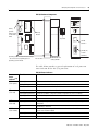
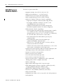
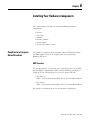
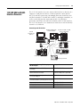
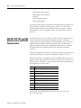
SLC 500 Modular
Hardware Style
Catalog Numbers
1747-L511, 1747-L514, 1747-L524,
1747-L531, 1747-L532, 1747-L533,
1747-L541, 1747-L542, 1747-L543,
1747-L551, 1747-L552, 1747-L553
User Manual
Important User Information
Solid state equipment has operational characteristics differing from those of
electromechanical equipment. Safety Guidelines for the Application,
Installation and Maintenance of Solid State Controls (publication SGI-1.1
available from your local Rockwell Automation sales office or online at
http://literature.rockwellautomation.com) describes some important
differences between solid state equipment and hard-wired electromechanical
devices. Because of this difference, and also because of the wide variety of
uses for solid state equipment, all persons responsible for applying this
equipment must satisfy themselves that each intended application of this
equipment is acceptable.
In no event will Rockwell Automation, Inc. be responsible or liable for
indirect or consequential damages resulting from the use or application of
this equipment.
The examples and diagrams in this manual are included solely for illustrative
purposes. Because of the many variables and requirements associated with
any particular installation, Rockwell Automation, Inc. cannot assume
responsibility or liability for actual use based on the examples and diagrams.
No patent liability is assumed by Rockwell Automation, Inc. with respect to
use of information, circuits, equipment, or software described in this manual.
Reproduction of the contents of this manual, in whole or in part, without
written permission of Rockwell Automation, Inc., is prohibited.
Throughout this manual, when necessary, we use notes to make you aware
of safety considerations.
WARNING
IMPORTANT
ATTENTION
Identifies information about practices or circumstances that can cause
an explosion in a hazardous environment, which may lead to personal
injury or death, property damage, or economic loss.
Identifies information that is critical for successful application and
understanding of the product.
Identifies information about practices or circumstances that can lead
to personal injury or death, property damage, or economic loss.
Attentions help you identify a hazard, avoid a hazard, and recognize
the consequence
SHOCK HAZARD
Labels may be on or inside the equipment, for example, a drive or
motor, to alert people that dangerous voltage may be present.
BURN HAZARD
Labels may be on or inside the equipment, for example, a drive or
motor, to alert people that surfaces may reach dangerous
temperatures.
SLC 5/03, SLC, SLC 500, MicroLogix, PanelBuilder, Data Highway Plus, PanelView 300, PanelView 550, PanelView 1000,
PanelView 300 Micro, PanelView 1400, DH+, MicroLogix, CompactLogix, FlexLogix, ControlLogix, DTAM, PLC-5, PLC-2, PLC-3,
RSLogix 500, RSLogix 5000, RSLinx, WINtelligent, Allen-Bradley, TechConnect, and Rockwell Automation are trademarks of
Rockwell Automation, Inc.
Trademarks not belonging to Rockwell Automation are property of their respective companies.
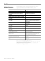
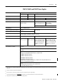
Summary of Changes
The information below summarizes the changes to this manual since
the last printing.
To help you find new and updated information in this release of the
manual, we have included change bars as shown to the right of this
paragraph.
3
For information on
See
Processor/network interface compatibility
page 18, page 26
Maximum distance between chassis when using a 1746-P4
power supply
page 19, page 61
New placement of memory module on SLC 5/01 processor
page 84, page 105
New placement of memory module on SLC 5/02 processor
page 86, page 105
1747-L533 processor specifications
page 88, page 178,
page 231, page 267
Power supply loading for the 1747-L511, 1747-L514, and
1747-L524 processor
throughout manual
Power supply loading for various modules
throughout manual
1746-P3 power supply
page 66, page 179
Memory module for the 1747-L533 processor
page 46
1747-L533 EEPROM burning option
page 47
Installing your memory module in the 1747-L533 processor
page 105
Specifications for SLC controllers and power supplies
appendix A
Change 10Base-T to 10/100Base-T
throughout manual
Publication 1747-UM011F-EN-P - May 2007
4
Summary of Changes
Notes:
Publication 1747-UM011F-EN-P - May 2007
Table of Contents
Preface
Who Should Use This Manual . . . . . . . . . .
Purpose of This Manual. . . . . . . . . . . . . . .
Additional Resources. . . . . . . . . . . . . . . . .
Common Techniques Used in This Manual.
Notes:. . . . . . . . . . . . . . . . . . . . . . . . . . . .
.
.
.
.
.
.
.
.
.
.
.
.
.
.
.
.
.
.
.
.
.
.
.
.
.
.
.
.
.
.
.
.
.
.
.
.
.
.
.
.
.
.
.
.
.
.
.
.
.
.
.
.
.
.
.
.
.
.
.
.
.
.
.
.
.
13
13
14
15
16
Chapter 1
Quick Start for Experienced Users Required Tools and Equipment . . . . . . . . . . . . . . . . . . . . . . 18
Procedures . . . . . . . . . . . . . . . . . . . . . . . . . . . . . . . . . . . . . 18
Chapter 2
Selecting Your Hardware
Components
5
European Union Directive Compliance . . . . . . . . . . . . . . . .
EMC Directive . . . . . . . . . . . . . . . . . . . . . . . . . . . . . . . .
Low Voltage Directive . . . . . . . . . . . . . . . . . . . . . . . . . .
Overview of Your Modular Control System . . . . . . . . . . . . .
Principles of Machine Control. . . . . . . . . . . . . . . . . . . . .
Selecting Modular Processors. . . . . . . . . . . . . . . . . . . . . . . .
Processor Features . . . . . . . . . . . . . . . . . . . . . . . . . . . . .
Processor Communication Options . . . . . . . . . . . . . . . . .
Selecting Discrete I/O Modules . . . . . . . . . . . . . . . . . . . . . .
Selecting Specialty I/O Modules. . . . . . . . . . . . . . . . . . . . . .
Selecting Power Supplies. . . . . . . . . . . . . . . . . . . . . . . . . . .
1746-P7 Current Capacity . . . . . . . . . . . . . . . . . . . . . . . .
Example for Selecting Power Supplies . . . . . . . . . . . . . .
Example Worksheet for Selecting a 1746 Power Supply . .
Selecting Enclosures . . . . . . . . . . . . . . . . . . . . . . . . . . . . . .
Selecting Operator Interfaces . . . . . . . . . . . . . . . . . . . . . . . .
Programming with a Personal Computer . . . . . . . . . . . . .
AIC+ Advanced Interface Converter (1761-NET-AIC) . . . .
1747-PIC RS-232/DH485 Interface Converter . . . . . . . . . .
1747-UIC USB to DH485 Interface Converter. . . . . . . . . .
Monitoring with a Data Table Access Module . . . . . . . . .
Monitoring with a PanelView or PanelView Plus Operator
Terminal . . . . . . . . . . . . . . . . . . . . . . . . . . . . . . . . . . . .
Selecting a Memory Module for the SLC 5/01 and SLC 5/02
Processors . . . . . . . . . . . . . . . . . . . . . . . . . . . . . . . . . . . . .
EEPROM Memory Modules. . . . . . . . . . . . . . . . . . . . . . .
Memory Backup for the 1747-L511, SLC 5/01 Processor . .
Selecting a Memory Module for SLC 5/03, SLC 5/04, and
SLC 5/05 Processors . . . . . . . . . . . . . . . . . . . . . . . . . . . . . .
EEPROM Burning Options. . . . . . . . . . . . . . . . . . . . . . . . . .
Selecting Isolation Transformers. . . . . . . . . . . . . . . . . . . . . .
Special Considerations. . . . . . . . . . . . . . . . . . . . . . . . . . . . .
Class I, Division 2 Applications. . . . . . . . . . . . . . . . . . . .
30
30
30
31
32
33
33
34
38
38
38
39
39
40
42
42
42
42
42
43
43
43
44
44
45
45
46
48
49
49
Publication 1747-UM011F-EN-P - May 2007
6
Table of Contents
Selecting Contact Protection . . . . . . . . . . . . . . . . . . . . . . 52
Chapter 3
System Installation
Recommendations
System Overview . . . . . . . . . . . . . . . . . . . . . . . . . . . . . . . . 58
Environment and Enclosure . . . . . . . . . . . . . . . . . . . . . . 58
Hazardous Location Considerations . . . . . . . . . . . . . . . . 59
Typical Installation . . . . . . . . . . . . . . . . . . . . . . . . . . . . . . . 60
Spacing Your Controller . . . . . . . . . . . . . . . . . . . . . . . . . . . 60
Preventing Excessive Heat . . . . . . . . . . . . . . . . . . . . . . . . . . 62
Grounding Guidelines . . . . . . . . . . . . . . . . . . . . . . . . . . . . . 63
Connect Equipment Grounding Conductor to Ground
Bus . . . . . . . . . . . . . . . . . . . . . . . . . . . . . . . . . . . . . . . . 63
Connect Ground Bus to Grounding-Electrode System . . . 64
Special Grounding Considerations for dc Applications using
1746-P3 (previous to revision B). . . . . . . . . . . . . . . . . . . 66
Determining the Date of the SLC 500 Series A Chassis . . . 68
Master Control Relay . . . . . . . . . . . . . . . . . . . . . . . . . . . . . . 68
Emergency-Stop Switches. . . . . . . . . . . . . . . . . . . . . . . . 69
Power Considerations . . . . . . . . . . . . . . . . . . . . . . . . . . . . . 70
Common Power Source . . . . . . . . . . . . . . . . . . . . . . . . . 70
Isolation Transformer . . . . . . . . . . . . . . . . . . . . . . . . . . . 70
Grounded ac Power-Distribution System with Master-Control
Relay. . . . . . . . . . . . . . . . . . . . . . . . . . . . . . . . . . . . . . . 71
Power Supply Required Input Voltage Characteristics . . . 71
Loss of Power Source. . . . . . . . . . . . . . . . . . . . . . . . . . . 72
Input States on Power Down . . . . . . . . . . . . . . . . . . . . . 72
Power Supply Undervoltage Operation . . . . . . . . . . . . . . 72
SLC 500 Operation with 24V dc User Power Overcurrent
Condition . . . . . . . . . . . . . . . . . . . . . . . . . . . . . . . . . . . 73
Safety Considerations . . . . . . . . . . . . . . . . . . . . . . . . . . . . . 74
Disconnecting Main Power. . . . . . . . . . . . . . . . . . . . . . . 74
Safety Circuits . . . . . . . . . . . . . . . . . . . . . . . . . . . . . . . . 74
Power Distribution. . . . . . . . . . . . . . . . . . . . . . . . . . . . . 74
Periodic Tests of Master Control Relay Circuit . . . . . . . . . 75
Preventive Maintenance. . . . . . . . . . . . . . . . . . . . . . . . . . . . 75
Notes:. . . . . . . . . . . . . . . . . . . . . . . . . . . . . . . . . . . . . . . . . 76
Chapter 4
Mounting Your SLC 500 Control
System
Publication 1747-UM011F-EN-P - May 2007
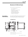
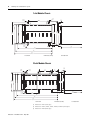
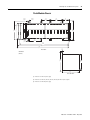
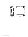
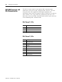
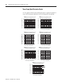
Mounting Modular Hardware Style Units
4-slot Modular Chassis . . . . . . . . . . .
7-slot Modular Chassis . . . . . . . . . . .
10-slot Modular Chassis . . . . . . . . . .
13-slot Modular Chassis . . . . . . . . . .
Link Coupler (AIC). . . . . . . . . . . . . .
.
.
.
.
.
.
.
.
.
.
.
.
.
.
.
.
.
.
.
.
.
.
.
.
.
.
.
.
.
.
.
.
.
.
.
.
.
.
.
.
.
.
.
.
.
.
.
.
.
.
.
.
.
.
.
.
.
.
.
.
.
.
.
.
.
.
.
.
.
.
.
.
.
.
.
.
.
.
.
.
.
.
.
.
.
.
.
.
.
.
77
77
78
78
79
80
Table of Contents
7
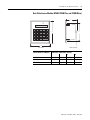
Data Table Access Module (DTAM, DTAM Plus, and DTAM
Micro) . . . . . . . . . . . . . . . . . . . . . . . . . . . . . . . . . . . . . . 81
AIC+ Advanced Interface Converter (1761-NET-AIC)
DeviceNet Interface (1761-NET-DNI)
Ethernet Interface (1761-NET-ENI) . . . . . . . . . . . . . . . . . 82
Chapter 5
Identifying the Components of
Your Processor
SLC 5/01 Processor Hardware Features . . . . .
SLC 5/02 Processor Hardware Features . . . . .
SLC 5/03 Processor Hardware Features . . . . .
SLC 5/04 Processor Hardware Features . . . . .
SLC 5/05 Processor Hardware Features . . . . .
Keyswitch for the
SLC 5/03, SLC 5/04, and SLC 5/05 Processors .
RUN Position . . . . . . . . . . . . . . . . . . . . . .
PROG Position. . . . . . . . . . . . . . . . . . . . .
REM Position . . . . . . . . . . . . . . . . . . . . . .
.
.
.
.
.
.
.
.
.
.
.
.
.
.
.
.
.
.
.
.
.
.
.
.
.
.
.
.
.
.
.
.
.
.
.
.
.
.
.
.
.
.
.
.
.
.
.
.
.
.
.
.
.
.
.
83
85
88
91
94
.
.
.
.
.
.
.
.
.
.
.
.
.
.
.
.
.
.
.
.
.
.
.
.
.
.
.
.
.
.
.
.
.
.
.
.
.
.
.
.
.
.
.
.
97
97
97
98
Chapter 6
Installing Your Hardware
Components
Compliance to European Union Directives .
EMC Directive . . . . . . . . . . . . . . . . . . .
Low Voltage Directive . . . . . . . . . . . . .
Install Your Chassis . . . . . . . . . . . . . . . . . .
Installing Your Processor. . . . . . . . . . . . . .
Install Modules . . . . . . . . . . . . . . . . . . . . .
Install Your Memory Module . . . . . . . . . . .
Remove the Memory Module . . . . . . . .
Install Your Power Supply. . . . . . . . . . . . .
Install Your Chassis Interconnect Cable . . .
Notes:. . . . . . . . . . . . . . . . . . . . . . . . . . . .
.
.
.
.
.
.
.
.
.
.
.
.
.
.
.
.
.
.
.
.
.
.
.
.
.
.
.
.
.
.
.
.
.
.
.
.
.
.
.
.
.
.
.
.
.
.
.
.
.
.
.
.
.
.
.
.
.
.
.
.
.
.
.
.
.
.
.
.
.
.
.
.
.
.
.
.
.
.
.
.
.
.
.
.
.
.
.
.
.
.
.
.
.
.
.
.
.
.
.
.
.
.
.
.
.
.
.
.
.
.
.
.
.
.
.
.
.
.
.
.
.
.
.
.
.
.
.
.
.
.
.
.
. 99
. 99
100
100
103
104
105
106
106
110
112
Defining Sinking and Sourcing. . . . . . . . . . .
Contact Output Circuits — ac or dc . . . .
Solid-State dc I/O Circuits . . . . . . . . . . .
Preparing Your Wiring Layout . . . . . . . . . . .
Recommendations for Wiring I/O Devices . .
Features of an I/O Module . . . . . . . . . . . . .
Wiring Your I/O Module . . . . . . . . . . . . . . .
Octal Label Kit Installation. . . . . . . . . . . . . .
Apply the Octal Filter Label . . . . . . . . . .
Apply the Octal Door Label . . . . . . . . . .
Octal Kit and I/O Module Information . .
Using the Removable Terminal Block (RTB).
Remove the RTB . . . . . . . . . . . . . . . . . .
.
.
.
.
.
.
.
.
.
.
.
.
.
.
.
.
.
.
.
.
.
.
.
.
.
.
.
.
.
.
.
.
.
.
.
.
.
.
.
.
.
.
.
.
.
.
.
.
.
.
.
.
.
.
.
.
.
.
.
.
.
.
.
.
.
.
.
.
.
.
.
.
.
.
.
.
.
.
.
.
.
.
.
.
.
.
.
.
.
.
.
.
.
.
.
.
.
.
.
.
.
.
.
.
.
.
.
.
.
.
.
.
.
.
.
.
.
.
.
.
.
.
.
.
.
.
.
.
.
.
.
.
.
.
.
.
.
.
.
.
.
.
.
113
114
114
116
117
118
118
119
119
119
120
121
121
Chapter 7
Wiring Your I/O Modules
Publication 1747-UM011F-EN-P - May 2007
8
Table of Contents
Install the RTB . . . . . . . . . . . . . . . . . . . . . . . . . . . . . . . 122
Chapter 8
Starting Up Your Control System
Procedures for Starting the Control System .
1. Inspect Your Installation . . . . . . . . . . . .
2. Disconnect Motion-Causing Device . . . .
3. Initialize and Test Your Processor . . . . .
4. Test Your Inputs . . . . . . . . . . . . . . . . . .
Input Troubleshooting Steps. . . . . . . . .
5. Test Your Outputs. . . . . . . . . . . . . . . . .
Output Troubleshooting Steps . . . . . . .
6. Enter and Test Your Program. . . . . . . . .
7. Observe Control Motion . . . . . . . . . . . .
8. Conduct a Dry Run . . . . . . . . . . . . . . . .
.
.
.
.
.
.
.
.
.
.
.
.
.
.
.
.
.
.
.
.
.
.
.
.
.
.
.
.
.
.
.
.
.
.
.
.
.
.
.
.
.
.
.
.
.
.
.
.
.
.
.
.
.
.
.
.
.
.
.
.
.
.
.
.
.
.
.
.
.
.
.
.
.
.
.
.
.
.
.
.
.
.
.
.
.
.
.
.
.
.
.
.
.
.
.
.
.
.
.
.
.
.
.
.
.
.
.
.
.
.
.
.
.
.
.
.
.
.
.
.
.
.
.
.
.
.
.
.
.
.
.
.
123
124
124
125
127
128
128
130
131
133
134
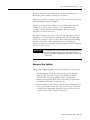
Handling and Storing Battery, Catalog Number 1747-BA . . .
Handling . . . . . . . . . . . . . . . . . . . . . . . . . . . . . . . . . . .
Storing . . . . . . . . . . . . . . . . . . . . . . . . . . . . . . . . . . . .
Transporting . . . . . . . . . . . . . . . . . . . . . . . . . . . . . . . .
Disposal . . . . . . . . . . . . . . . . . . . . . . . . . . . . . . . . . . .
Install and Replace the Battery of the SLC 5/01 or SLC 5/02
Processor . . . . . . . . . . . . . . . . . . . . . . . . . . . . . . . . . . . . .
Replace Your SLC 5/03, SLC 5/04, or SLC 5/05 Battery . . . .
Replacing Retainer Clips on an I/O Module . . . . . . . . . . . .
Remove Damaged Retainer Clips . . . . . . . . . . . . . . . . .
Install New Retainer Clips . . . . . . . . . . . . . . . . . . . . . .
Replace a Fuse on the Power Supply . . . . . . . . . . . . . . . . .
135
135
136
136
137
Chapter 9
Maintaining Your Control System
138
139
140
141
141
141
Chapter 10
Troubleshooting
Publication 1747-UM011F-EN-P - May 2007
Contacting Rockwell Automation for Assistance . . . . . . . . . 143
Tips for Troubleshooting Your Control System . . . . . . . . . . 144
Removing Power . . . . . . . . . . . . . . . . . . . . . . . . . . . . . 144
Replacing Fuses . . . . . . . . . . . . . . . . . . . . . . . . . . . . . . 145
Program Alteration. . . . . . . . . . . . . . . . . . . . . . . . . . . . 145
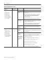
Troubleshooting the SLC 5/01 and SLC 5/02 Processors . . . 145
Identifying SLC 5/01 and SLC 5/02 Processor Errors. . . . 146
Identifying SLC 5/02 Processor Communication Errors . . 150
Troubleshooting the SLC 5/03, SLC 5/04, and
SLC 5/05 Processors . . . . . . . . . . . . . . . . . . . . . . . . . . . . . 151
Clearing SLC 5/03, SLC 5/04, and SLC 5/05 Processor Faults
Using the Keyswitch . . . . . . . . . . . . . . . . . . . . . . . . . . 151
Identifying SLC 5/03, SLC 5/04, and SLC 5/05 Processor
Errors . . . . . . . . . . . . . . . . . . . . . . . . . . . . . . . . . . . . . 152
Table of Contents
9
Identifying SLC 5/03, SLC 5/04, and SLC 5/05 Processor
Communication Errors . . . . . . . . . . . . . . . . . . . . . . . . . 157
Identifying Processor Errors while Downloading an Operating
System . . . . . . . . . . . . . . . . . . . . . . . . . . . . . . . . . . . . . . . 161
Returning the SLC 5/03, SLC 5/04, and SLC 5/05
Processors to Initial Factory Conditions. . . . . . . . . . . . . 163
Troubleshooting Your Input Modules. . . . . . . . . . . . . . . . . 165
Input Circuit Operation . . . . . . . . . . . . . . . . . . . . . . . . 165
Troubleshooting Your Input Modules . . . . . . . . . . . . . . 166
Troubleshooting Your Output Modules . . . . . . . . . . . . . . . 167
Output Circuit Operation . . . . . . . . . . . . . . . . . . . . . . . 167
Troubleshooting Your Output Modules. . . . . . . . . . . . . 168
Notes:. . . . . . . . . . . . . . . . . . . . . . . . . . . . . . . . . . . . . . . . 170
Chapter 11
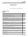
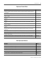
Replacement Parts
Replacement Cables and Connectors
Cable Connectivity Summary . . .
Replacement Terminal Blocks. . .
Other Replacement Hardware. . .
Notes:. . . . . . . . . . . . . . . . . . . . . . .
.
.
.
.
.
.
.
.
.
.
.
.
.
.
.
.
.
.
.
.
.
.
.
.
.
.
.
.
.
.
.
.
.
.
.
.
.
.
.
.
.
.
.
.
.
.
.
.
.
.
.
.
.
.
.
.
.
.
.
.
.
.
.
.
.
.
.
.
.
.
.
.
.
.
.
.
.
.
.
.
.
.
.
.
.
171
172
173
173
176
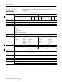
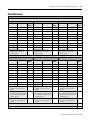
SLC 500 System General Specifications. . . . . . . . . . . . . . . .
Processor General Specifications . . . . . . . . . . . . . . . . . . . .
Power Supply Specifications . . . . . . . . . . . . . . . . . . . . . . .
1746-P1, 1746-P2, 1746-P3, and 1746-P4 Power Supplies
1746-P5, 1746-P6, and 1746-P7 Power Supplies . . . . . . .
177
178
179
179
181
Appendix A
Specifications
Appendix B
Setting Up the DH-485 Network
DH-485 Network Description. . . . . . . . . . . . . . . . . . .
DH-485 Network Protocol . . . . . . . . . . . . . . . . . . . . .
DH-485 Token Rotation. . . . . . . . . . . . . . . . . . . . . . .
DH-485 Network Initialization . . . . . . . . . . . . . . . . . .
Devices that Use the DH-485 Network . . . . . . . . . . . .
1747-AIC Isolated Link Coupler for DH-485 . . . . . . . .
1747-UIC USB to DH-485 Interface Converter. . . . . . .
Example System Configuration . . . . . . . . . . . . . . . . .
Configuring the SLC 5/03, SLC 5/04, and SLC 5/05
Channel 0 for DH485 Protocol . . . . . . . . . . . . . . .
Important Planning Considerations . . . . . . . . . . . . . .
Hardware Considerations . . . . . . . . . . . . . . . . . . .
Software Considerations . . . . . . . . . . . . . . . . . . . .
Installing the DH-485 Network . . . . . . . . . . . . . . . . .
DH-485 Communication Cable and Isolated Link
Coupler . . . . . . . . . . . . . . . . . . . . . . . . . . . . . . . .
.
.
.
.
.
.
.
.
.
.
.
.
.
.
.
.
.
.
.
.
.
.
.
.
.
.
.
.
.
.
.
.
183
184
184
184
185
186
187
189
.
.
.
.
.
.
.
.
.
.
.
.
.
.
.
.
.
.
.
.
190
191
191
193
195
. . . . 195
Publication 1747-UM011F-EN-P - May 2007
10
Table of Contents
Installing the DH-485 Communication Cable . . . . . . . . . 195
Connecting the Communication Cable to the Isolated Link
Coupler . . . . . . . . . . . . . . . . . . . . . . . . . . . . . . . . . . . . 196
Powering the Link Coupler. . . . . . . . . . . . . . . . . . . . . . 198
Installing and Attaching the Link Couplers . . . . . . . . . . 201
Appendix C
RS-232 Communication Interface
RS-232 and SCADA Applications . . . . . . . . . . . . . . . . . .
RS-232 Communication Interface Overview . . . . . . . . . .
SLC 5/03, SLC 5/04, and SLC 5/05 processors and RS-232
Communication. . . . . . . . . . . . . . . . . . . . . . . . . . . . . . .
SLC 500 Devices that Support RS-232 Communication. . .
1747-KE Module . . . . . . . . . . . . . . . . . . . . . . . . . . .
1746-BAS and 1746-BAS-T Modules . . . . . . . . . . . . .
DF1 Protocol and the SLC 5/03, SLC 5/04, and SLC 5/05
Processors . . . . . . . . . . . . . . . . . . . . . . . . . . . . . . . . . .
DF1 Full-duplex Protocol . . . . . . . . . . . . . . . . . . . . .
Full-duplex (Point-to-Point) . . . . . . . . . . . . . . . . . . .
DF1 Half-duplex Protocol. . . . . . . . . . . . . . . . . . . . .
DF1 Radio Modem Channel 0 Driver . . . . . . . . . . . .
ASCII Communication . . . . . . . . . . . . . . . . . . . . . . . . . .
DF1 Communication Protocol Modems Overview. . . . . .
Wiring Connectors for RS-232 Communication . . . . . . . .
Types of RS-232 Connectors . . . . . . . . . . . . . . . . . . .
DTE Pinout . . . . . . . . . . . . . . . . . . . . . . . . . . . . . . .
DCE Pinout . . . . . . . . . . . . . . . . . . . . . . . . . . . . . . .
Pin Assignments for Wiring Connectors. . . . . . . . . . .
Applications for the RS-232 Communication Interface . . .
DF1 Full-duplex Peer-to-peer . . . . . . . . . . . . . . . . . .
Half-duplex with Slave-to-slave Routing . . . . . . . . . .
. . 203
. . 203
.
.
.
.
.
.
.
.
204
205
205
205
.
.
.
.
.
.
.
.
.
.
.
.
.
.
.
.
.
.
.
.
.
.
.
.
.
.
.
.
.
.
206
206
207
207
209
212
212
213
213
213
214
214
221
221
222
Data Highway Plus Communication Protocol Overview . .
SLC 5/04 Processors and DH+ Communication. . . . . . . . .
DH+ Channel 1, 3-Pin . . . . . . . . . . . . . . . . . . . . . . . .
DH+ Channel 1, 8-Pin . . . . . . . . . . . . . . . . . . . . . . . .
Wiring Connectors for DH+ Communication for SLC 5/04
Processors . . . . . . . . . . . . . . . . . . . . . . . . . . . . . . . . . . .
Minimizing Noise . . . . . . . . . . . . . . . . . . . . . . . . . . . .
Typical DH+ Network Configuration . . . . . . . . . . . . . . . .
Notes:. . . . . . . . . . . . . . . . . . . . . . . . . . . . . . . . . . . . . . .
.
.
.
.
223
224
224
224
.
.
.
.
226
227
228
229
Appendix D
Setting Up the DH+ Network
Appendix E
Power Supply Worksheet
Publication 1747-UM011F-EN-P - May 2007
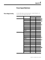
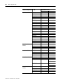
Power Supply Loading . . . . . . . . . . . . . . . . . . . . . . . . . . . 231
Blank Worksheet . . . . . . . . . . . . . . . . . . . . . . . . . . . . . . . 234
Table of Contents
11
Appendix F
Control Networks
Allen-Bradley Remote I/O Network . . . . . . . . . . . .
Remote I/O Passthru . . . . . . . . . . . . . . . . . . . .
DeviceNet Network. . . . . . . . . . . . . . . . . . . . . . . .
The 1747-SDN DeviceNet Scanner . . . . . . . . . .
The 1761-NET-DNI DeviceNet Interface . . . . . .
DeviceNet Network Length. . . . . . . . . . . . . . . .
ControlNet Network . . . . . . . . . . . . . . . . . . . . . . .
The 1747-SCNR ControlNet Scanner Module . . .
The 1747-KFC15 ControlNet Messaging Module.
.
.
.
.
.
.
.
.
.
.
.
.
.
.
.
.
.
.
.
.
.
.
.
.
.
.
.
.
.
.
.
.
.
.
.
.
.
.
.
.
.
.
.
.
.
.
.
.
.
.
.
.
.
.
235
236
237
237
238
239
240
240
240
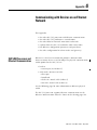
Appendix G
Communicating with Devices on
an Ethernet Network
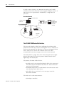
SLC 5/05 Processors and Ethernet Communication . . . . . . . 241
SLC 5/05 Performance Considerations . . . . . . . . . . . . . . . . 242
SLC 5/05 Processor and Personal Computer Connections to the
Ethernet Network . . . . . . . . . . . . . . . . . . . . . . . . . . . . . . . 243
Ethernet Network Topology . . . . . . . . . . . . . . . . . . . . . 243
Ethernet Channel 1 8-pin 10Base-T Connector. . . . . . . . 244
Cables . . . . . . . . . . . . . . . . . . . . . . . . . . . . . . . . . . . . . 244
Ethernet Connections . . . . . . . . . . . . . . . . . . . . . . . . . . . . 244
Configuring the Ethernet Channel on the SLC 5/05
Processor . . . . . . . . . . . . . . . . . . . . . . . . . . . . . . . . . . . . . 245
Configuration Using RSLogix 500 Programming Software . . 246
Configuration Via BOOTP . . . . . . . . . . . . . . . . . . . . . . . . . 246
Use the Rockwell BOOTP Utility . . . . . . . . . . . . . . . . . 248
Using DCHP Software To Configure Your Processor . . . . . . 249
Using Subnet Masks and Gateways . . . . . . . . . . . . . . . . . . 250
Manually Configuring Channel 1 for Processors on
Subnets . . . . . . . . . . . . . . . . . . . . . . . . . . . . . . . . . . . . 251
SLC 5/05 Processor Embedded Web Server Capability . . . . 252
Module Information . . . . . . . . . . . . . . . . . . . . . . . . . . . 253
TCP/IP Configuration Data (Read Only) . . . . . . . . . . . . 253
Diagnostic Information. . . . . . . . . . . . . . . . . . . . . . . . . 254
Data Table Memory Map . . . . . . . . . . . . . . . . . . . . . . . 255
Data Table Monitor . . . . . . . . . . . . . . . . . . . . . . . . . . . 256
User Provided Pages . . . . . . . . . . . . . . . . . . . . . . . . . . 257
Notes:. . . . . . . . . . . . . . . . . . . . . . . . . . . . . . . . . . . . . . . . 264
Appendix H
Calculating Heat Dissipation for
the SLC 500 Control System
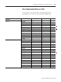
Definition of Key Terms . . . . . . . . . . . . . .
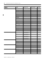
Calculating Module Heat Dissipation . . . . .
Calculated Watts vs. Total Watts . . . . . .
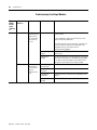
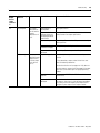
Power Supply Loading Reference Table
Power Supply Heat Dissipation Graphs.
Example Heat Dissipation Calculation . . . .
.
.
.
.
.
.
.
.
.
.
.
.
.
.
.
.
.
.
.
.
.
.
.
.
.
.
.
.
.
.
.
.
.
.
.
.
.
.
.
.
.
.
.
.
.
.
.
.
.
.
.
.
.
.
.
.
.
.
.
.
.
.
.
.
.
.
.
.
.
.
.
.
265
265
266
267
270
271
Publication 1747-UM011F-EN-P - May 2007
12
Table of Contents
Example Worksheet . . . . . . . . . . . . . . . . . . . . . . . . . . . . . 272
Blank Worksheet . . . . . . . . . . . . . . . . . . . . . . . . . . . . . . . 273
Glossary
Index
Publication 1747-UM011F-EN-P - May 2007
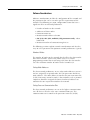
Preface
Read this preface to familiarize yourself with the rest of the manual. It
provides information concerning:
•
•
•
•
Who Should Use This
Manual
who should use this manual.
the purpose of this manual.
related documentation.
conventions used in this manual.
Use this manual if you are responsible for designing, installing,
programming, or troubleshooting control systems that use SLC 500
programmable controllers.
You must have a basic understanding of electrical circuitry and
familiarity with relay logic.
Purpose of This Manual
This manual describes the procedures you use to install, wire, and
troubleshoot your controller. This manual:
• explains how to install and wire your controllers.
• gives you an overview of the SLC 500 programmable controller
system.
Refer to the SLC 500 Instruction Set reference manual, publication
1747-RM001, for the SLC 500 instruction set and for application
examples to show the instruction set in use. Refer to your
programming software user documentation for more information on
programming your SLC 500 programmable controller.
13
Publication 1747-UM011F-EN-P - May 2007
14
Preface
Additional Resources
The table below provides a listing of publications that contain
important information about SLC 500 controller systems.
Resource
Description
SLC 500 System Overview, publication 1747-SG001
An overview of the SLC 500 family of products.
SLC 5/03 and SLC 5/04 Processors Firmware/Operating
System Upgrade Installation Instructions, publication
1747-IN007
Details on the latest operating system upgrade to the
SLC 5/03 and SLC 5/04 processors.
SLC 5/05 Processors Firmware/Operating System ControlFlash Information on the SLC 5/05 ControlFlash upgrade.
Upgrade Installation Instructions, publication 1747-IN019
SLC 500 Instruction Set Reference Manual, publication
1747-RM001
Detailed information on the SLC instruction set.
Advanced Interface Converter (AIC+) User Manual, publication A description on how to install and connect an AIC+
1761-UM004
interface. This manual also contains information on
network wiring.
DeviceNet Interface User Manual, publication 1761-UM005
Information on how to install, configure, and commission
a DNI interface.
MicroLogix Ethernet Interface User Manual, publication
1761-UM006
Information on using the 1761-NET-ENI Ethernet
interface.
DF1 Protocol and command Set Reference Manual, publication Information on DF1 protocol.
1770-6.5.16
System Design for Control of Electrical Noise, publication
GMC-RM001
Information on reducing electrical noise.
Allen-Bradley Programmable controller Grounding and Wiring Information on grounding and wiring Allen-Bradley
Guidelines, publication 1770-4.1
programmable controllers.
Application Considerations for Solid-state Controls,
publication SGI-1.1
A description of important differences between
solid-state programmable controller products and
hard-wired electromechanical devices.
National Electrical Code - Published by the National Fire
Protection Association of Boston, MA
An article on wire sizes and types for grounding electrical
equipment.
Allen-Bradley Industrial Automation Glossary, publication
AG-7.1
A glossary of industrial automation terms and
abbreviations.
You can view or download publications at
http://literature.rockwellautomation.com. To order paper copies of
technical documents, contact your local Rockwell Automation
distributor or sales representative.
Publication 1747-UM011F-EN-P - May 2007
Preface
Common Techniques Used
in This Manual
15
The following conventions are used throughout this manual:
• Bulleted lists, such as this one, provide information, not
procedural steps.
• Numbered lists provide sequential steps or hierarchical
information.
Publication 1747-UM011F-EN-P - May 2007
16
Preface
Notes:
Publication 1747-UM011F-EN-P - May 2007
Chapter
1
Quick Start for Experienced Users
This chapter can help you to get started using the SLC 500 Modular
Processors. We base the procedures here on the assumption that you
have an understanding of SLC 500 products. You should understand
electronic process control and be able to interpret the ladder logic
instructions required to generate the electronic signals that control
your application.
Because it is a start-up guide for experienced users, this chapter does
not contain detailed explanations about the procedures listed. It does,
however, reference other chapters in this book where you can get
more information.
If you have any questions or are unfamiliar with the terms used or
concepts presented in the procedural steps, always read the
referenced chapters and other recommended documentation before
trying to apply the information.
This chapter:
•
•
•
•
•
•
17
tells you what tools and equipment you need.
lists how to install your chassis.
lists how to install and wire your power supply.
lists how to install and apply power to your processor.
lists how to establish communication with the processor.
describes how to return the SLC 5/03, SLC 5/04, and SLC 5/05
processors to initial factory conditions if required.
Publication 1747-UM011F-EN-P - May 2007
18
Quick Start for Experienced Users
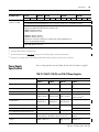
Required Tools and
Equipment
Have the following tools and equipment ready:
• Medium blade screwdriver
• Programming equipment
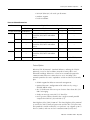
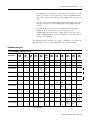
• Compatible communication cable and/or interface (The table
below indicates with an X, which cables are compatible with the
SLC 5/01 through 5/05 processors.)
Network Interface
Processor
SLC 5/01
SLC 5/02
SLC 5/03
SLC 5/04
X(4)
X(4)
X
X
X
1747-UIC
X(1)
X(1)
X(1)(4)
1747-PIC
X
X
X
1747-CP3
1784-PKTX(D)
X(2)
X(2)
X(2)
X
1784-PCMK
X(3)
X(3)
X(3)
X(5)
10/100Base-T Ethernet
(1)
Requires 1747-C13 cable.
(2)
Requires 1784-CP14 cable.
(3)
Requires 1784-PCM4 cable.
(4)
Requires 1747-CP3 cable.
(5)
Requires 1784-PCM6 cable.
X
Procedures
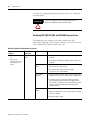
1.
Check the contents of the shipping box.
Unpack the shipping boxes making sure that the contents include:
• SLC 500 modular processor
– installation instructions (publication 1747-IN009)
• SLC 500 modular chassis (catalog numbers 1746-A4, 1746-A7, 1746-A10, or
1746-A13)
– installation instructions (publication 1746-IN016)
• SLC 500 modular power supplies (catalog numbers 1746-P1, 1746-P2,
1746-P3, 1746-P4, 1746-P5, 1746-P6, or 1746-P7)
– installation instructions (publication 1746-IN004)
If the contents are incomplete, call your local Rockwell Automation representative
for assistance.
Publication 1747-UM011F-EN-P - May 2007
SLC 5/05
Reference
Quick Start for Experienced Users
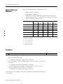
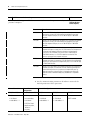
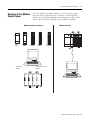
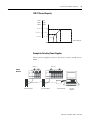
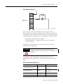
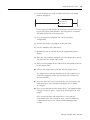
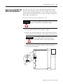
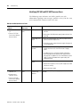
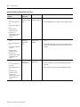
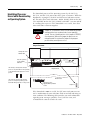
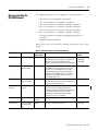
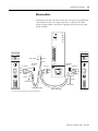
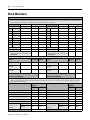
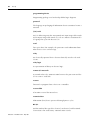
2.
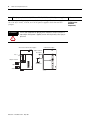
Install the chassis.
19
Reference
Chapter 3
(System Installation
Recommendations)
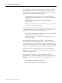
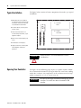
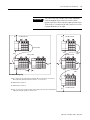
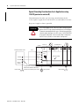
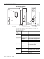
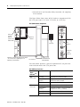
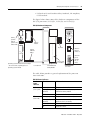
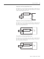
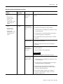
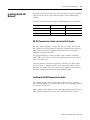
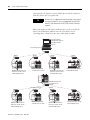
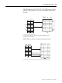
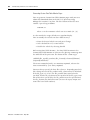
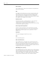
1. Determine the amount of spacing required for mounting your system.
C
C
1746-C9 Cable
SLC 500 Controller
A
A
SLC 500 Controller
1746-C7 Cable
B
B
C
SLC 500 Controller
D
1746-C9
Cable
B
B
SLC 500 Controller
A
SLC 500 Controller
1746-C9
Cable
Recommended Spacing
B
A. 15.3...20.0 cm (6...8 in.) when using the 1746-C9 cable. If you mount two 13-slot chassis
above each other, the distance cannot exceed 10.2...12.7 cm (4...5 in.).
B. Greater than 10.2 cm (4 in.).
C. Greater than 15.3 cm (6 in.).
D. 6.35...10.2 cm (2.5...4 in.) when using the 1746-C7 cable. If you are using a 1746-P4
power supply, your maximum spacing is 6.35 cm (2.5 in.).
SLC 500 Controller
C
Publication 1747-UM011F-EN-P - May 2007
20
Quick Start for Experienced Users
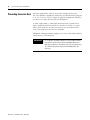
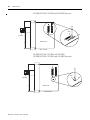
2. Drill holes in the backpanel of your enclosure and install the top mounting
hardware. Use M4 or M5 (#10 or #12) phillips screw and star washer (or
SEM screw).
3. Scrape off the paint from the backpanel between the chassis and backpanel.
4. Slide the chassis over the installed hardware and tighten the screws.
5. Install the remaining tab hardware.
Publication 1747-UM011F-EN-P - May 2007
Chapter 6
(Installing Your
Hardware Components)
Quick Start for Experienced Users
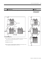
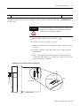
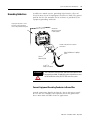
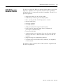
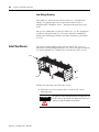
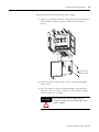
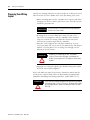
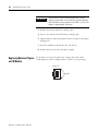
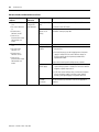
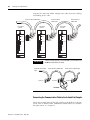
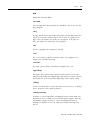
3.
Install the power supply.
21
Reference
1. Align the circuit board of the power supply with the card guides on the left
side of the chassis, and slide the power supply in until it is flush with the
chassis.
Chapter 6
(Installing Your
Hardware Components)
2. Fasten the power supply to the chassis.
Use these screws to fasten the power supply to the chassis.
1.2 Nm (11 lb-in) Maximum Torque
Publication 1747-UM011F-EN-P - May 2007
22
Quick Start for Experienced Users
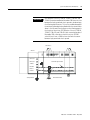
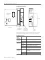
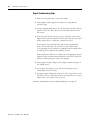
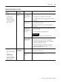
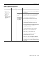
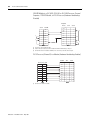
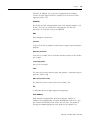
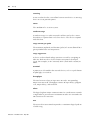
4.
Make jumper selection for 120/240V ac on 1746-P1, 1746-P2, and 1746-P4 power supplies.
Place the input voltage jumper to match the input voltage. This does not apply to
the 1746-P3, 1746-P5, 1746-P6, or 1746-P7 power supplies which do not have
jumpers.
Set the input jumper before applying power. Hazardous voltage is present on
exposed pins when power is applied; contact with the pin may cause injury to
personnel.
ATTENTION
1746-P1 and 1746-P2 Power Supplies
POWER
1746-P4 Power Supply
Jumper Selection
85-132V ac
Fuse
Jumper Selection
100/120 Volts
200/240 Volts
Publication 1747-UM011F-EN-P - May 2007
170-250V ac
POWER
Reference
Chapter 6
(Installing Your
Hardware
Components)
Quick Start for Experienced Users
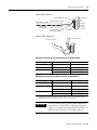
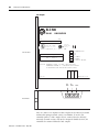
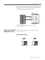
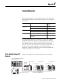
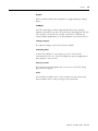
5.
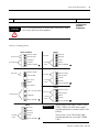
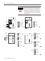
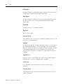
Wire power to the power supply.
ATTENTION
23
Reference
Turn off incoming power before connecting wires. Failure to do so could
cause injury to personnel and/or equipment.
Chapter 6
(Installing Your
Hardware
Components)
Connect incoming power.
1746-P1 and 1746-P2
1746-P3
NOT USED
PWR OUT +24V dc
User Power
PWR OUT COM
User Power
NOT USED
+24V dc
120/240V ac
Incoming Power
V ac NEUT
CHASSIS GROUND
Incoming
Power
1746-P4
User Power
dc NEUT
CHASSIS GROUND
1746-P5
PWR OUT +24V dc
PWR OUT COM
PWR OUT +24V dc
User Power
PWR OUT COM
+125V dc
85 to 132V ac
JUMPER
Incoming
Power
dc NEUT
CHASSIS GROUND
170 to 250V ac
1746-P6
L1: 85 to 132/170 to 250V ac
Incoming Power
L2: NEUTRAL
PWR OUT +24V dc
User Power
Incoming
Power
CHASSIS GROUND
1746-P7
NOT USED
NOT USED
+12/24V dc
Incoming
Power
dc NEUT
CHASSIS GROUND
PWR OUT COM
+48V dc
dc NEUT
CHASSIS GROUND
IMPORTANT
Terminal screws on the 1746-P1, 1746-P2, 1746-P3,
1746-P5, 1746-P6, and 1746-P7 power supplies
should be tightened with a maximum torque of 1 Nm
(8.8 lb-in).
Terminal screws on the 1746-P4 power supply
should be tightened with a max torque of 0.8 Nm
(7 lb-in).
Publication 1747-UM011F-EN-P - May 2007
24
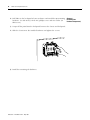
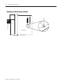
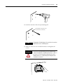
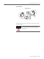
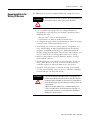
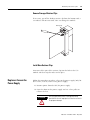
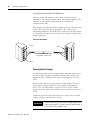
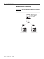
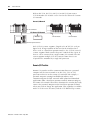
6.
Quick Start for Experienced Users
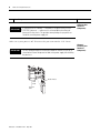
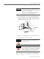
Install the processor.
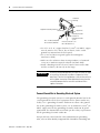
IMPORTANT
Reference
If your processor has a battery — the battery is an option for the SLC 5/01
(1747-L511) processor — make sure it is connected before installing your
processor into the chassis. This provides memory backup for your processor
should the controller power supply fail.
Chapter 2
(Selecting Your
Hardware
Components)
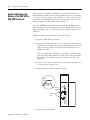
Make sure system power is off. Then insert the processor into the 1746 chassis.
IMPORTANT
The SLC 500 modular processor must be inserted into the left slot (slot 0), as
shown below. Remove the protective label on the power supply after installing
the processor.
Module Release
Card
Guide
Protective
Label
Publication 1747-UM011F-EN-P - May 2007
Chapter 6
(Installing Your
Hardware
Components)
Quick Start for Experienced Users
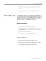
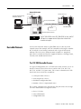
7.
Apply power to the processor.
25
Reference
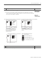
1. Energize the chassis power supply.
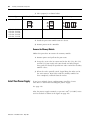
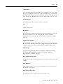
2. Check the chassis power supply and processor status indicators. The power
status indicator on the power supply should be on and the fault status indicator
on the processor should be flashing.
Chapter 8
(Starting Up Your
Control System)
Chapter 10
(Troubleshooting)
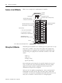
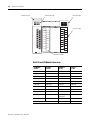
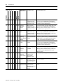
Power supply and SLC 5/01 and SLC 5/02 processor status indicators Power supply and SLC 5/03 and SLC 5/04 processor status indicators
POWER
RUN
COMM
CPU FAULT
FORCED I/O
BATTERY LOW
The RUN status indicator on the SLC 5/01
processor is actually labeled PC RUN. Also,
the SLC 5/01 processor does not have a
COMM status indicator.
Power supply and SLC 5/05 processor status indicators
POWER
RUN
FORCE
FLT
BATT
DH485
RS232
The DH485 status indicator on the SLC 5/03
processor is labeled DH+ on the SLC 5/04
processor.
Refer to the following key to determine the
status of the status indicators:
POWER RUN
FORCE
Indicates the status indicator is off.
FLT
BATT
ENET
RS232
Indicates the status indicator is on.
Indicates the status indicator is FLASHING.
Status of status indicator does not matter.
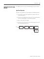
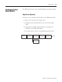
8.
Load your software.
Refer to your software package’s documentation.
Reference
—
Publication 1747-UM011F-EN-P - May 2007
26
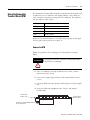
9.
Quick Start for Experienced Users
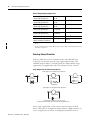
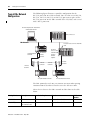
Establish communication to the processor.
Reference
Refer to the following to establish communication between the processor and your
personal computer.
Chapter 8
(Starting Up Your
Control System)
Processor
Procedure
SLC 5/01
Connect 1747-PIC interface from the processor to your personal computer
serial port or connect 1747-UIC interface from the processor to your
personal computer USB port, or use a 1784-PKTX(D) or 1784-PMCK
interface.
SLC 5/02
Connect 1747-PIC interface from the processor to your personal computer
serial port or connect 1747-UIC interface from the processor to your
personal computer USB port, or use a 1784-PKTX(D) or 1784-PMCK
interface.
SLC 5/03
Connect the 1747-PIC interface from the processor to your personal
computer serial port or connect the 1747-UIC interface from the processor
to your personal computer USB port to the processor by using the
1747-C13 or 1747-CP3 cable. You can also use a 1784-PKTX(D) or
1784-PCMK interface, or a 1747-CP3 cable from channel 0 of the
processor to the personal computer serial port.
SLC 5/04
Connect a 1747-CP3 cable from channel 0 of the processor to the personal
computer serial port or connect the 1747-UIC interface from channel 0 of
the processor to your personal computer USB port, or use a 1784-PKTX(D)
or 1784-PCMK interface.
SLC 5/05
Connect a 1747-CP3 cable from channel 0 of the processor to the personal
computer serial port, or connect the 1747-UIC interface converter from
channel 0 of the processor to your personal computer USB port. For
Ethernet connection, connect channel 1 of the processor and the PC
Ethernet card to an Ethernet hub by using 10/100Base-T compatible
cable.(1)
(1)
EtherNet/IP address must first be set via BOOTP or an RS-232 connection. See appendix C for more information.
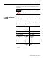
1. Set the communication parameters of software to match the
default parameters of the processor.
Comms Channel
Channel 0
Configuration
Channel 1 Configuration
SLC 5/01 and 5/02
SLC 5/03, 5/04, and 5/05 SLC 5/03
SLC 5/04
SLC 5/05
DH-485:
DF1 Full-duplex:
DH+:
Ethernet:
DH-485:
• 19.2 Kbaud
• no handshaking
• 19.2 Kbaud
• 57.6 Kbaud
• node address = 1
• 19.2 Kbaud
• node address = 1
• node address = 1
• CRC Error Check
• duplicate packet,
detect on
• no parity
Publication 1747-UM011F-EN-P - May 2007
BOOTP enabled
Quick Start for Experienced Users
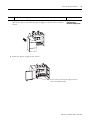
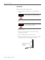
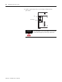
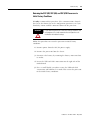
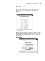
10.
(Optional) Return the SLC 5/03, SLC 5/04, or SLC 5/05 processor to initial factory conditions.
Use this procedure if the communication channels are shut down due to
configuration parameters, or if you absolutely cannot establish communication with
the processor.
27
Reference
Chapter 10
(Troubleshooting)
If you return the processor to the initial factory conditions, the
communication configurations are returned to their default
settings and the user program is cleared.
ATTENTION
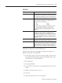
1. Remove power from the SLC 500 power supply.
2. Remove the processor from the chassis.
3. Disconnect the battery by removing the battery connector from
its socket.
4. Locate the VBB and GND connections on the right side of the
motherboard.
5. Place a small bladed screwdriver across the VBB and GND
connections and hold for 60 seconds. This returns the processor
to the initial factory conditions.
VBB
GND
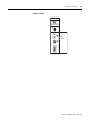
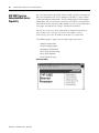
SLC 5/03 Processors (1747-L531, 1747-L532, and 1747-L533)
Keyswitch
GND
Mother Board
VBB
Mother Board
Right Side View
Publication 1747-UM011F-EN-P - May 2007
28
Quick Start for Experienced Users
SLC 5/04 Processors (1747-L541, 1747-L542, and 1747-L543)
SLC 5/05 Processors (1747-L551, 1747-L552, and 1747-L553)
GND
VBB
Keyswitch
GND VBB
Mother Board
Mother Board
Right Side View
Publication 1747-UM011F-EN-P - May 2007
Chapter
2
Selecting Your Hardware Components
This chapter provides general information on what your SLC 500
controller can do, an overview of the modular control system, and
special considerations for controller installations. It also explains how
to select:
•
•
•
•
•
•
•
•
•
chassis.
modular processors.
discrete I/O modules.
specialty I/O modules.
power supplies.
enclosures.
operator interfaces.
memory modules.
isolation transformers.
This chapter does not provide you with all the information that you
need to select a complete SLC 500 control system. To do this, we
recommend that you use the latest version of the system overview,
SLC 500 Programmable Controllers and I/O Modules, publication
1747-SG001.
29
Publication 1747-UM011F-EN-P - May 2007
30
Selecting Your Hardware Components
European Union Directive
Compliance
If this product has the CE mark it is approved for installation within
the European Union and EEA regions. It has been designed and tested
to meet the following directives.
EMC Directive
This product is tested to meet Council Directive 89/336/EEC
Electromagnetic Compatibility (EMC) and the following standards, in
whole or in part, documented in a technical construction file:
• EN 50081-2
EMC - Generic Emission Standard, Part 2 - Industrial
Environment
• EN 50082-2
EMC - Generic Immunity Standard, Part 2 - Industrial
Environment
This product is intended for use in an industrial environment.
Low Voltage Directive
This product is tested to meet Council Directive 73/23/EEC Low
Voltage, by applying the safety requirements of EN 61131-2
Programmable Controllers, Part 2 – Equipment Requirements and
Tests.
For specific information required by EN61131-2, see the appropriate
sections in this publication, as well as the Industrial Automation
Wiring and Grounding Guidelines for Noise Immunity, publication
1770-4.1.
Publication 1747-UM011F-EN-P - May 2007
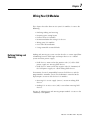
Selecting Your Hardware Components
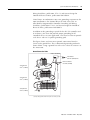
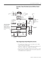
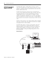
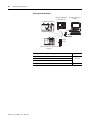
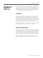
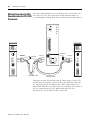
Overview of Your Modular
Control System
The basic modular controller consists of a chassis, power supply,
processor (CPU), Input/Output (I/O modules), and an operator
interface device for programming and monitoring. The figure below
shows typical hardware components for a modular controller.
Modular Controller
Modular Hardware Components
Power
Supply
Processor
Module
31
Input
Module
Output
Module
Combination
I/O Module
OR
Programming Personal
Computer
Programming
Terminal
Chassis
Publication 1747-UM011F-EN-P - May 2007
32
Selecting Your Hardware Components
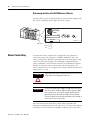
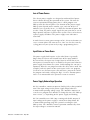
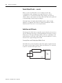
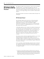
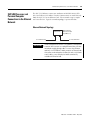
Principles of Machine Control
You enter a ladder logic program into the controller by using the
software. The logic program is based on your electrical relay print
diagrams. It contains instructions that direct control of your
application.
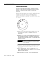
With the ladder logic program entered into the controller, placing the
controller in the Run mode initiates an operating cycle. The
controller’s operating cycle consists of a series of operations
performed sequentially and repeatedly, unless altered by your ladder
logic program.
➄
Overhead
➀
Input
Scan
Service
Comms
➃
➁
Operation
Cycle
Program
Scan
Output
Scan
➂
1. Input scan - The time required for the controller to scan and
read all input data; typically accomplished within a few
milliseconds.
2. Program scan - The time required for the processor to execute
the instruction in the program. The program scan time varies
depending on the instruction used and each instruction’s status
during the scan time.
IMPORTANT
Subroutine and interrupt instructions within your logic
program may cause deviations in the way the operating
cycle is sequenced.
3. Output scan - The time required for the controller to scan and
write all output data; typically accomplished within a few
milliseconds.
4. Service communication - The part of the operating cycle in
which communication takes place with other devices, such as an
HHT or a personal computer.
5. Housekeeping and overhead - The time spent on memory.
Publication 1747-UM011F-EN-P - May 2007
Selecting Your Hardware Components
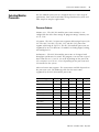
Selecting Modular
Processors
33
SLC 500 modular processors are designed to meet a wide range of
applications, from small stand-alone to large distributed systems and
from simple to complex applications.
Processor Features
Memory size - The SLC 500 modular processors memory is user
configurable for either data storage or program storage. Memory size
is 1 K...64 K.
I/O points - The SLC 5/01 processor supports addressing of up to 3940
I/O. The SLC 5/02, SLC 5/03, SLC 5/04, and SLC 5/05 processors
support addressing of 4096 I/O. The SLC 500 modular processors are
supported by over 60 different I/O modules including digital, analog,
and intelligent I/O.
Performance - The SLC 500 modular processors are designed with
throughput performance in mind. The program scan time for a typical
instruction mix are 0.9 ms/K...8.0 ms/K depending on the processor.
I/O scan times are 0.25 ms...2.6 ms depending on the processor and
I/O installed in the system.
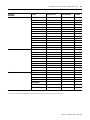
Advanced instruction support - The instructions available depends on
the processor used. The following table lists the instructions
supported by the SLC 500 modular processors.
Instruction Support
SLC 5/01
SLC 5/02
SLC 5/03
SLC 5/04
SLC 5/05
Bit
•
•
•
•
•
Timer and Controller
•
•
•
•
•
Comparison
•
•
•
•
•
Basic Math
•
•
•
•
•
Move, Copy, and Bit Shift
•
•
•
•
•
Sequencer
•
•
•
•
•
Jump and Subroutine
•
•
•
•
•
Messaging
•
•
•
•
STI
•
•
•
•
FIFO/LIFO
•
•
•
•
PID
•
•
•
•
•
•
•
Advanced Math and Trig
Publication 1747-UM011F-EN-P - May 2007
34
Selecting Your Hardware Components
Instruction Support
SLC 5/01
SLC 5/02
SLC 5/03
SLC 5/04
SLC 5/05
Indirect Addressing
•
•
•
Floating Point Math
•
•
•
ASCII
•
•
•
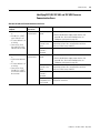
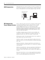
Processor Communication Options
The SLC 500 processors support several communication options. The
following sections describe the available physical connections and
protocol options used by the SLC 500 processors.
Physical Connection Options
Ethernet (10/100Base-T) channel offers:
• 10/100 Mbps communication rate.
• ISO/IEC 8802-3STD 802.3 (RJ45) connector for 10/100Base-T
media.
• TCP/IP communication protocol.
• built-in isolation.
Data Highway Plus (DH+) channel offers:
• communication rates of 57.6 Kbaud, 115.2 Kbaud, and 230.4
Kbaud.
• maximum network length of 3048 m (10,000 ft) at 57.6 Kbaud
• Belden 9463 (blue hose) cable connection between nodes (daisy
chain connection).
• built-in isolation.
DH-485 channel offers:
• configurable isolation via the 1747-AIC or 1761-NET-AIC
interfaces.
• maximum network length of 1219 m (4000 ft).
• RS-485 electrical specifications.
• Belden 9842 or Belden 3106A cable connection between nodes
(daisy-chain connection).
RS-232 channel offers:
• communication rates up to 19.2 Kbaud (38.4 Kbaud SLC 5/04
and SLC 5/05 processors).
• maximum distance between devices is 15.24 m (50 ft).
Publication 1747-UM011F-EN-P - May 2007
Selecting Your Hardware Components
35
• RS-232C (EIA-232) electrical specifications.
• modem support.
• built-in isolation.
Processor Channel Connections
Processor
Physical Communication Channel
DH-485
RS-232
DH+
Ethernet
—
—
—
—
—
—
—
—
—
DH+ protocol
—
—
—
—
EtherNet TCP/IP protocol
SLC 5/01 and SLC 5/02 DH-485 protocol
SLC 5/03
channel 0
—
channel 1
SLC 5/04
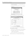
DH-485 protocol
channel 0
—
channel 1
SLC 5/05
—
(1)
—
DH-485(1), DF1 full-duplex, DF1 half-duplex
master/slave, ASCII, and DF1 radio modem
protocols
—
channel 0
channel 1
DH-485(1), DF1 full-duplex, DF1 half-duplex
master/slave, ASCII, and DF1 radio modem
protocols
—
DH-485(1), DF1 full-duplex, DF1 half-duplex
master/slave, ASCII, and DF1 radio modem
protocols
—
—
An 1761-NET-AIC interface is required when connecting to a DH-485 network.
Protocol Options
EtherNet TCP/IP Protocol - Standard Ethernet, utilizing the TCP/IP
protocol, is used as the backbone network in many office and
industrial buildings. Ethernet is a local area network that provides
communication between various devices at 10/100 Mbps. This
network provides the same capabilities as DH+ or DH-485 networks,
plus:
• SNMP support for Ethernet network management.
• optional dynamic configuration of IP addresses by using a
BOOTP/DHCP utility.
• SLC 5/05 Ethernet data rate up to 40 times faster than SLC 5/04
DH+ messaging.
• ability to message entire SLC 5/05 data files.
• much greater number of nodes on a single network possible
compared to DH-485 (32) and DH+ (64).
Data Highway Plus (DH+) Protocol - The Data Highway Plus protocol
is used by the PLC-5 family of processors and the SLC 5/04 processor.
This protocol is similar to DH-485, except that it can support up to 64
devices (nodes) and runs at faster communication (baud) rates.
Publication 1747-UM011F-EN-P - May 2007
36
Selecting Your Hardware Components
DH-485 Protocol - The SLC 500 processors have a DH-485 channel
that supports the DH-485 communication network. This network is a
multi-master, token-passing network protocol capable of supporting
up to 32 devices (nodes). This protocol allows:
• monitoring data and processor status, along with program
uploading and downloading of any device on the network from
one location.
• SLC processors to pass data to each other (peer-to-peer
communication).
• operator interface devices on the network to access data from
any SLC processor on the network.
DF1 full-duplex protocol - DF1 full-duplex protocol (also referred to
as DF1 point-to-point protocol) lets two devices communicate with
each other at the same time. This protocol allows:
• transmission of information across modems (dial-up, leased line,
radio, or direct cable connections).
• communication to occur between Allen-Bradley products and
third-party products.
DF1 half-duplex protocol (master and slave) - DF1 half-duplex
protocol provides a multi-drop single master/multiple slave network
capable of supporting up to 255 devices (nodes). This protocol also
provides modem support and is ideal for SCADA (Supervisory Control
and Data Acquisition) applications because of the network capability.
ASCII protocol - The ASCII protocol provides connection to other
ASCII devices, such as bar code readers, weigh scales, serial printers,
and other intelligent devices.
DF1 radio modem protocol - The DF1 radio modem protocol,
optimized for use with radio modem networks, is a hybrid between
DF1 full-duplex protocol and DF1 half-duplex protocol. DF1 radio
modem:
• supports Store and Forward capability.
• uses a node address (0...254) on channel 0.
Publication 1747-UM011F-EN-P - May 2007
Selecting Your Hardware Components
37
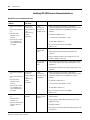
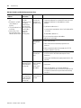
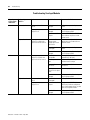
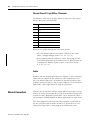
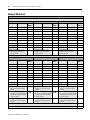
SLC Communication Options
Communication
Protocol
Processor
SLC 5/01
DH-485 peer-to-peer receive only
DH-485 via RS232
port
DF1 via RS232 port
(full-duplex or
half-duplex master
or slave)
ASCII via RS232 port
Data Highway Plus
(DH+)
Ethernet
DeviceNet
ControlNet
—
receive only(1)
—
receive only(2)
SLC 5/02
SLC 5/03
receive and initiate
receive and initiate
SLC 5/05
—
—
receive and initiate(9)
receive and initiate(9)
receive and initiate(9)
receive and initiate
receive and initiate
receive and initiate
receive and initiate
receive and initiate
receive and initiate
receive and initiate(5)
receive and initiate
receive and initiate(5)
receive and initiate(6)
receive and initiate(6)
receive and initiate
—
receive only(1)
—
SLC 5/04
receive only(2)
—
—
—
receive and
initiate(3)
receive and
initiate(3)(7)
receive and
initiate(3)(7)
receive and
initiate(3)(7)
—
receive and
initiate(4)
receive and
initiate(4)(8)
receive and
initiate(4)(8)
receive and
initiate(4)(8)
(1)
A 1747-KE or 1770-KF3 interface is required to bridge from DF1 (full-duplex or half-duplex slave only) to DH485 network.
(2)
A ControlLogix gateway with a 1746-DHRIO interface and a 1756-DH485 interface is required to bridge from DH+ to DH-485 network.
(3)
A 1747-SDN module is required for scanning I/O and for explicit messaging on DeviceNet network.
(4)
A 1747-SCNR module is required for scanning I/O and for explicit messaging on ControlNet network.
(5)
The SLC 5/04’s channel-to-channel passthru feature may be used to bridge between DH+ and DH-485 network or between DH+ and DF1 full-duplex network (DH+ to DF1
full-duplex passthru available starting with OS401). Another option is to use the 1785-KE interface to bridge between DH+ and DF1 full-duplex or DH+ and DF1 half-duplex
master/slave network.
(6)
A 1761-NET-ENI interface is required to bridge from DF1 full-duplex to Ethernet network.
(7)
A 1761-NET-DNI interface is required to bridge from DF1 to DeviceNet network.
(8)
A 1747-KFC15 module or 1770-KFC15 interface is required to bridge from DF1 to ControlNet network.
(9)
If using 1747-AIC interface for isolation, connect to DH-485 network using 1747-PIC interface. If using a 1761-NET-AIC interface for isolation, connect directly to DH-485
network with 1747-CP3 serial cable (or equivalent RS-232 null-modem cable).
TIP
The 1785-KE module requires the use of a 1771 series chassis
and power supply.
Publication 1747-UM011F-EN-P - May 2007
38
Selecting Your Hardware Components
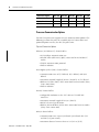
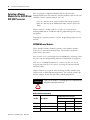
Selecting Discrete I/O
Modules
There are three types of discrete I/O modules: input, output, and
combination. They are available in a wide variety of densities
including 4, 8, 16, and 32 point and can interface to ac, dc, and TTL
voltage levels. Output modules are available with solid-state ac,
solid-state dc, and relay contact type outputs.
For a complete listing of discrete I/O modules and specifications,
contact your Allen-Bradley sales office for the latest selection guide,
publication 1747-SG001.
Selecting Specialty I/O
Modules
The SLC 500 family offers specialty I/O modules that enhance your
control system. Modules range in function from analog interface to
motion control, from communication to high-speed counting.
For a complete listing of specialty I/O modules and their
specifications, contact your Allen-Bradley sales office for the latest
selection guide, 1747-SG001.
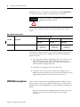
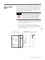
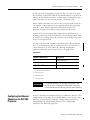
Selecting Power Supplies
To select a power supply, you need:
• power supply specifications.
• power supply worksheet, one for each chassis.
• SLC 500 Systems Selection Guide, publication 1747-SG001.
When configuring a modular system, you must have a power supply
for each chassis. Careful system configuration will result in the best
performance. Excessive loading of the power supply outputs can
cause a power supply shutdown or premature failure.
There are three different ac power supplies and four dc power
supplies. For ac power supplies, the 120/240V selection is made by a
jumper. Place the jumper to match the input voltage.
ATTENTION
Ensure that the power supply jumper is in the correct position
before supplying power to the SLC 500 system or personal
injury or damage to the system may result.
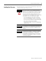
SLC power supplies have an status indicator that illuminates when the
power supply is functioning properly.
Publication 1747-UM011F-EN-P - May 2007
Selecting Your Hardware Components
39
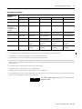
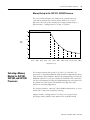
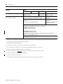
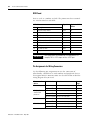
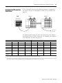
1746-P7 Current Capacity
24V dc
Output
Current
5V dc
Output
Current
0.87 A
3.6 A
0.625 A
2.64 A
0.46A
2.0 A
Input Voltage (dc)
10V
12.2V15V
19.2V
30V
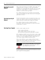
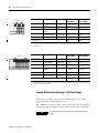
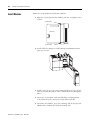
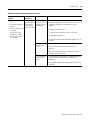
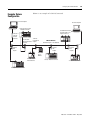
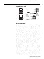
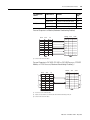
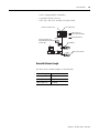
Example for Selecting Power Supplies
Select a power supply for chassis 1 and chassis 2 in the control system
below.
Chassis 1
Chassis 2
DH-485
Network
?
?
1747-AIC Interface
?
?
1747-AIC Interface
1747-PIC Interface
Personal
Computer
Publication 1747-UM011F-EN-P - May 2007
40
Selecting Your Hardware Components
Chassis 1
Slot
0
Slot Numbers
Description
Cat. No.
Power Supply at Power Supply at
5V dc (Amps)
24V dc (Amps)
0
Processor unit
1747-L511
0.090
0.000
1
Input module
1747-IV8
0.050
0.000
2
Transistor output
module
1746-OB8
0.135
0.000
3
Triac output module
1746-OA16
0.370
0.000
Peripheral device
Isolated link coupler
1747-AIC
0.000
0.085
0.645
0.085(1)
Total Current:
(1)
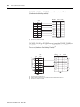
Chassis 2
?
Slot
0
The 1746-P1 power supply is sufficient for Chassis #1. The internal current capacity for this power supply is 2 A at 5V dc,
0.46 A at 24V dc.
Slot Numbers
Description
Cat. No.
Power Supply at Power Supply at
5V dc (Amps)
24V dc (Amps)
0
Processor unit
1747-L514
0.090
0.000
1
Output module
1746-OW16
0.170
0.180
2
Combination module
1746-IO12
0.090
0.070
3, 4, 5, 6
Analog output
modules
1746-NO4I
0.220
(4 x 0.055)
0.780
(4 x 0.195)
Peripheral device
Isolated link coupler
1747-AIC
0.000
0.085
Peripheral device
Interface converter
1746-PIC
Not applicable
Not applicable
0.570
1.115(1)
1
Total Current:
(1)
The 1746-P4 power supply is sufficient for Chassis #2. The internal current capacity for this power supply is 10 A at 5V dc,
2.88 A at 24V dc; not to exceed 70 W.
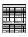
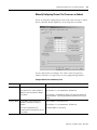
Example Worksheet for Selecting a 1746 Power Supply
If you have a multiple chassis system, make copies of the Power
Supply Worksheet found on page 234.
For a detailed list of device load currents, refer to the SLC 500 Modular
Chassis and Power Supplies Technical Data, publication 1746-TD003.
TIP
Publication 1747-UM011F-EN-P - May 2007
Consider future system expansion when selecting a power
supply.
Selecting Your Hardware Components
41
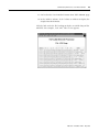
Procedure
1. For each slot of the chassis that contains a module, list the slot number, the catalog number of the module, and its 5V and 24V maximum currents. Also
include the power consumption of any peripheral devices that may be connected to the processor other than a DTAM or PIC device—the power
consumption of these devices is accounted for in the power consumption of the processor.
Chassis Number
Slot Number
1
Cat. No.
Maximum Currents
Chassis Number
at 5V dc
Slot Number
at 24V dc
2
Cat. No.
Maximum Currents
at 5V dc
at 24V dc
Slot
0
1747-L511
0.090 A
0.000 A
Slot
0
1747-L514
0.090 A
0.000 A
Slot
1
1746-IV8
0.050 A
-
Slot
1
1746-OW16
0.170 A
0.180 A
Slot
2
1746-OB8
0.135 A
-
Slot
2
1746-NO4I
0.055 A
0.195 A
Slot
3
1746-OA16
0.370 A
-
Slot
3
1746-NO4I
0.055 A
0.195 A
Slot
Slot
4
1746-NO4I
0.055 A
0.195 A
Slot
Slot
5
1746-NO4I
0.055 A
0.195 A
Slot
Slot
6
1746-IO12
0.090 A
0.070 A
Slot
Slot
1747-AIC
-
0.085 A
0.570 A
1.115 A
Peripheral Device
1747-AIC
-
0.085 A
Peripheral Device
Peripheral Device
Peripheral Device
2.Add the loading currents of all the system
devices at 5 and 24V dc to determine the
Total Current.
0.645 A
0.085 A
2.Add the loading currents of all the system
devices at 5 and 24V dc to determine the
Total Current.
3.For 1746-P4 power supplies, calculate the total power consumption of all system devices. If you are not using a 1746-P4 power supply, go to step 4.
Current
Multiply by = Watts
Current
Total Current at 5V dc
0.645 A
5V
3.225 W
Total Current at 5V dc
0.570 A
5V
2.850 W
Total Current
at 24V dc
0.085 A
24V
2.040 W
Total Current
at 24V dc
1.115 A
24V
26.76 W
User Current
at 24V dc
0.500 A
24V
12.00 W
User Current
at 24V dc
0.500 A
24V
12.00 W
17.26 W
Add the Watts values to determine Total Power
Add the Watts values to determine Total Power
(cannot exceed 70 Watts)
Multiply by = Watts
41.61 W
(cannot exceed 70 Watts)
4.Choose the power supply from the list of catalog numbers shown below. Compare the Total Current required for the chassis with the Internal Current
capacity of the power supplies. Be sure that the Total Current consumption for the chassis is less than the Internal Current Capacity for the power
supply, for both 5V and 24V loads.
Cat. No.
Internal Current
Capacity
at 5V dc
at 24V dc
1746-P1
2.0 A
0.46 A
1746-P2
5.0 A
1746-P3
3.6 A
1746-P4 (see step 3)
1746-P5
1746-P6
1746-P7
(1)
(1)
Internal Current
Capacity
at 5V dc
at 24V dc
1746-P1
2.0 A
0.46 A
0.96 A
1746-P2
5.0 A
0.96 A
0.87 A
1746-P3
3.6 A
0.87 A
10.0 A
2.88 A
1746-P4 (see step 3)
10.0 A
2.88 A
5.0 A
0.96 A
1746-P5
5.0 A
0.96 A
1746-P6
5.0 A
0.96 A
12V dc input
2.0 A
0.46 A
24V dc input
3.6 A
0.87 A
Required Power Supply
Cat. No.
1746-P1
(1)
1746-P7
5.0 A
0.96 A
12V dc input
2.0 A
0.46 A
24V dc input
3.6 A
0.87 A
Required Power Supply
1746-P4
See 1746-P7 current capacity graph on page 39.
Publication 1747-UM011F-EN-P - May 2007
42
Selecting Your Hardware Components
Selecting Enclosures
The enclosure protects the equipment from atmospheric
contamination. Standards established by the National Electrical
Manufacturer’s Association (NEMA) define enclosure types, based on
the degree of protection an enclosure will provide. Use a fan to
circulate the air of sealed enclosures that use convection cooling to
dissipate heat. Select a NEMA-rated enclosure that suits your
application and environment. The enclosure should be equipped with
a disconnect device. To calculate the heat dissipation of your
controller, see appendix H.
Selecting Operator
Interfaces
Use an operator interface to program and/or monitor your SLC 500
controller. You can choose from several Allen-Bradley operator
interface devices.
Programming with a Personal Computer
Contact Rockwell Software or your local Allen-Bradley distributor for
specifications and availability of software packages available to
program the SLC 500 Modular Controllers.
AIC+ Advanced Interface Converter (1761-NET-AIC)
The AIC+ advanced interface converter provides communication links
between various networked devices. It has three communication
ports: one for DH-485 and two for RS-232. The AIC+ converter is
compatible with a variety of SLC and MicroLogix controllers and
peripherals.
1747-PIC RS-232/DH485 Interface Converter
For communication with a SLC 5/01, SLC 5/02, or SLC 5/03 processor,
you can use an RS-232/DH-485 interface convertor (catalog number
1747-PIC) between the computer and SLC controller. The converter
includes a 279.4 mm (11 in.) ribbon cable, already attached to the
converter, for connection to the computer serial port and a catalog
number 1746-C10 cable for connection to the controller.
If you are using an SLC 5/03, SLC 5/04, or SLC 5/05 processor, you do
not need the 1747-PIC interface. You can program via the RS-232
channel using DF1 full-duplex protocol or DH485 protocol and RS-232
program cable (catalog number 1747-CP3).
Publication 1747-UM011F-EN-P - May 2007
Selecting Your Hardware Components
43
1747-UIC USB to DH485 Interface Converter
For communication with an SLC 5/01 through SLC 5/05 processor, you
can connect the 1747-UIC interface between the computer’s USB port
and the SLC controller. The 1747-UIC interface features an RS-232 port
for communication with SLC 5/03 and later processors and an RS-485
port for communication with SLC 5/03 and previous processors.
Monitoring with a Data Table Access Module
The Data Table Access Module (DTAM) is a plant floor device that lets
you access data file information, change operating modes, monitor
and clear processor faults, and transfer the user program between
RAM and an EEPROM memory module with any SLC 5/01, SLC 5/02,
or SLC 5/03 (except for the 1747-L533 processor) processor. You
cannot use it to create new programs. Important features of DTAM
include:
• shorthand addressing, which provides easier access to data files.
• display prompts in six, user-selectable languages: English,
French, German, Italian, Spanish, and Japanese.
• UL listed to US and Canadian Safety Standards.
• NEMA type 12 and 13 enclosures.
• point-to-point interface to an SLC family processor, or as a
network device on a DH-485 network.
Monitoring with a PanelView or PanelView Plus Operator
Terminal
The PanelView or PanelView Plus operator terminals provide operator
interface capabilities in space-saving, flat-panel designs. Offering
optimum viewing angles, these electronic operator interfaces feature
pixel graphics and high-performance functionality in both color and
monochrome displays. The PanelView operator terminals let you enter
input by using function keys or a touch screen, depending upon the
model.
All PanelView and PanelView Plus operator terminals are available
with DF1 or DH-485 (RS-232) communication capability, letting them
communicate directly with channel 0 on an SLC 5/03, SLC 5/04, or SLC
5/05 processor. The larger versions also offer DH-485 (RJ-45), DH+,
Remote I/O, Ethernet, DeviceNet, and ControlNet network
connectivity.
Publication 1747-UM011F-EN-P - May 2007
44
Selecting Your Hardware Components
Selecting a Memory
Module for the SLC 5/01 and
SLC 5/02 Processors
You can plug these optional EEPROM (Electrically Erasable
Programmable Read Only Memory) memory modules into the SLC 500
controller. With a memory module, you can:
• save the contents of the processor RAM for storage purposes.
• load the contents of the EEPROM memory into the processor
RAM.
Adapter sockets (catalog number 1747-M5) are required when
inserting EEPROMs or UVPROMs into the programming and erasing
equipment.
To program a memory module, see your programming software user
manual.
EEPROM Memory Modules
These optional memory modules provide a non-volatile memory
back-up in a convenient modular form. The modules plug into a
socket on the processor.
You can store (save) your program in the EEPROM by inserting it into
the processor and programming software to download the program.
You can use an EEPROM module as a master, or you can use an
archived processor file as the source by using the software PROM
translator utility.
Adapter sockets are required when inserting memory modules into
commercially available PROM programmer. The memory module fits
into the adapter socket and then into a PROM programmer.
ATTENTION
Make sure the adapter is inserted properly into the programming
equipment or damage could result.
Memory Module Compatibility
Use with this processor type
Cat. No.
Description
SLC 5/01
1747-L511
Publication 1747-UM011F-EN-P - May 2007
SLC 5/02
1747-L514
1747-L524
1747-M1
1 K User Words EEPROM
X
X
X
1747-M2
4 K User Words EEPROM
X
X
X
1747-M5
Adapter Socket
X
X
X
Selecting Your Hardware Components
45
Memory Backup for the 1747-L511, SLC 5/01 Processor
The curve below illustrates the ability of the memory back-up
capacitor to maintain the contents of the RAM in a 1747-L511
processor. To back up the memory for a longer period of time, a
lithium battery, catalog number 1747-BA, is required.
Capacitor Memory Back-up Time VS Temperature
30
25
20
Time
(Days)
15
10
5
0
0
5
(41˚F)
10
(50˚F)
15
(59˚F)
20
(68˚F)
25
(77˚F)
30
(86˚F)
35
40
45
50
55
60
(95˚F) (104˚F) (113˚F) (122˚F) (131˚F) (140˚F)
Temperature °C (°F)
Selecting a Memory
Module for SLC 5/03,
SLC 5/04, and SLC 5/05
Processors
The memory module for the SLC 5/03, SLC 5/04, and SLC 5/05
processors is called Flash EPROM (Flash Erasable Programmable Read
Only Memory). Flash EPROMs combine the programming versatility of
EEPROMs with the security precautions of UVPROMs. This means that
you have the option of leaving your EPROM programs write-protected
or unprotected. Write-protect the EPROM by using either your
software or a PROM programmer.
The memory modules consist of a Flash EPROM mounted on a circuit
board with a connector and plastic housing.
Adapter sockets (catalog number 1747-M15) are required when
inserting memory modules into commercially available PROM
Publication 1747-UM011F-EN-P - May 2007
46
Selecting Your Hardware Components
programmer. The 1747-M15 Series B adapter socket is required for
use with the memory module (catalog number 1747-M13).
ATTENTION
Make sure the adapter is inserted properly in the programming
equipment or damage could result.
See the table below for details on the Flash EPROM and adapter
socket.
Memory Module Compatibility
Use with this processor type
Cat. No.
SLC 5/03
Description
SLC 5/04
SLC 5/05
1747-L531, 1747-L532, 1747-L541, 1747-L542, 1747-L551, 1747-L552,
1747-L533
1747-L543
1747-L553
1747-M13
Supports up to 64 K of user-memory backup
X
(Series C
OS302 or later)
X
(Series C
OS401 or later)
X
(Series C
OS501 or later)
To program a memory module, refer to your programming software
user manual or help resource. Follow this procedure to program a
memory module.
1. Set the memory module configuration bits (S:1/10 to S:1/12) in
your offline program file. Refer to SLC 500 Instruction Set
Reference Manual, publication 1747-RM001, for details on the
Memory Module Configuration Bits.
2. Download your program file to your processor.
3. Go online with the processor and burn the program to the
EEPROM memory module (per the instructions outlined in your
programming software user manual or help resource).
EEPROM Burning Options
You can burn a program into an EEPROM memory module using a
processor that is the same or different from the one used to run the
program. When burning EEPROMs, keep the following conditions in
mind:
• The processor burning the EEPROM must be of the same type
and have the same OS version or lower than the target
processor.
Publication 1747-UM011F-EN-P - May 2007
Selecting Your Hardware Components
47
• The program size cannot exceed the processor memory size. For
instance, an SLC 5/01 4 K processor can burn an EEPROM for a
SLC 5/01 1 K processor as long as the program does not exceed
1 K.
• The I/O and chassis configuration of the burning processor does
not have to match the I/O configuration of the program being
burned.
• You do not have to enter the Run mode before burning an
EEPROM. If the run mode is entered and the chassis
configuration does not match, a major fault will occur. If you
burn an EEPROM while in the fault mode, the fault will also be
saved in the EEPROM.
The following table summarizes the above conditions as to the type of
processor you can use to burn EEPROMs for other processors.
EEPROM Burning Options
To burn EEPROMs for these processors
SLC
5/05
(16K)
SLC
5/05
(32K)
SLC
5/05
(64K)
SLC 5/05 (16K)
•
16 K
max
16 K
max
SLC 5/05 (32K)
16 K
max
•
32 K
max
SLC 5/05 (64K)
16 K
max
32 K
max
•
SLC
5/04
(16K)
SLC
5/04
(32K)
SLC
5/04
(64K)
SLC 5/04 (16K)
•
16 K
max
16 K
max
SLC 5/04 (32K)
16 K
max
•
32 K
max
SLC 5/04 (64K)
16 K
max
32 K
max
•
SLC
5/03
SLC
5/03
(8K)
SLC
5/03
(16K)
(32K)
SLC 5/03 (8K)
•
8K
max
8K
max
SLC 5/03 (16K)
8K
max
•
16 K
max
SLC 5/03 (32K)
8K
max
16 K
max
•
SLC
5/01
(1K)
SLC
5/01
(4K)
SLC 5/01 (1K)
•
1 K max
SLC 5/01 (4K)
1 K max
•
Use these
processors
SLC 5/02 (4K)
SLC
5/02
(4K)
•
• valid combination
Publication 1747-UM011F-EN-P - May 2007
48
Selecting Your Hardware Components
Selecting Isolation
Transformers
If there is high frequency conducted noise in or around your
distribution equipment, use an isolation transformer in the ac line to
the power supply. This type of transformer provides isolation from
your power distribution system and is often used as a step down
transformer to reduce line voltage. Any transformer used with the
controller must have a sufficient power rating for its load. This power
rating is generally expressed in voltamperes (VA).
To select an appropriate isolation transformer, calculate the power
required by the chassis power supply (or supplies if more than one
chassis in system) and any input circuits and output loads that are
connected through this transformer.
You can find the power requirement (VA rating) for the chassis power
supplies in the specifications starting on page 179. The power
requirement for the input circuits is determined by the number of
inputs, the operating voltage, and the nominal input current. The
power requirement for output loads is determined by the number of
outputs, the load voltage, and load current.
For example, if you have a 1746-P1 power supply, a 16-point ac input
module, catalog number 1746-IA16, (12 mA at 120V ac) and a 16-point
ac triac output module, catalog number 1746-OA16, (0.5A at 120V ac),
the power consumed would be:
135VA + (16)(120V)(0.012 A) + (16)(120V)(0.5 A) = 1118VA
IMPORTANT
In this case, 0.5 A is the maximum rating of the triac output at 30
°C (86 °F). If the load draws less than 0.5 A, this figure may be
reduced accordingly. The output portion of the VA calculation
should reflect the current requirements of selected loads.
In general, we recommend that the transformer is oversized to
provide some margin for line voltage variations and other factors.
Typically a transformer that is 25% larger than the calculated VA is
sufficient.
Most industrial environments are susceptible to power transients or
spikes. To help insure fault-free operation and protection of
equipment, use suppression devices on power line to the equipment
in addition to the isolation equipment.
Publication 1747-UM011F-EN-P - May 2007
Selecting Your Hardware Components
Special Considerations
49
The recommendations given previously provide favorable operating
conditions for most controller installations. Some applications may
involve adverse conditions, such as excessive line voltage variations
and/of excessive noise, as described below. Additional measures can
be taken to minimize the effect of these conditions.
Class I, Division 2 Applications
IMPORTANT
When installing peripheral devices (for example, push buttons,
lamps) into a hazardous environment, ensure that they are Class
I, Division 2 certified, or determined to be safe for the
environment.
Excessive Line Voltage Variations
The best solution for excessive line voltage variation is to correct any
feeder problems in your distribution system. Where this does not
solve the line variation problem, or in certain critical applications, use
a constant voltage transformer. If you require a constant voltage
transformer, connect it to the power supply and all input devices
connected to the SLC 500 controller.
Connect output devices on the same power line, but their connection
along the power line is normally made before the constant voltage
transformer. A constant voltage transformer must have a sufficient
power rating for its load.
Excessive Noise
When operating the SLC 500 controller in an environment with a high
amount of electrical noise, give special consideration to the possibility
of electrical interference.
The following reduces the effect of electrical interference.
•
•
•
•
•
SLC 500 controller design features
Proper mounting of controller within an enclosure
Proper equipment grounding
Proper routing of wires (power, communication, control lines)
Proper suppression added to noise generating devices
Potential sources of noise include inductive loads, such as relays,
solenoids, and motor starters when operated by hard contacts like
push buttons or selector switches. Suppression may be necessary
Publication 1747-UM011F-EN-P - May 2007
50
Selecting Your Hardware Components
when such loads are connected as output devices or when connected
to the same supply line that powers the controller.
Lack of surge suppression on inductive loads may contribute to
processor faults and sporadic operation. RAM can be corrupted (lost)
and I/O modules may appear to be faulty or reset themselves.
For extremely noisy environments, use a memory module and
program it for auto-loading on processor fault or power cycle for
quick recovery.
Selecting Surge Suppressors
Most output modules have built-in surge suppression to reduce the
effects of high voltage transients. However, you should use an
additional suppression device if an output module is being used to
control an inductive device such as:
•
•
•
•
relays.
motor starters.
solenoids.
motors.
Additional suppression is especially important if your inductive device
is in series with or parallel to a hard contact such as:
• push buttons.
• selector switches.
By adding a suppression device directly across the coil of an inductive
device, you reduce the effects of voltage transients caused by
interrupting the current to that inductive device and prolong the life of
the switch contacts. You also prevent electrical noise from radiating
into system wiring. The diagram below shows an output module with
a suppression device.
Publication 1747-UM011F-EN-P - May 2007
Selecting Your Hardware Components
51
Surge Suppression Diagram
+ dc or L1
VAC/VDC
Snubber
Out 0
Out 1
Out 2
ac or dc
Output Module
Out 3
Out 4
Out 5
Out 6
Out 7
COM
dc COM or L2
If you connect an SLC 500 controller triac output to control an
inductive load, use varistors to suppress noise. Choose a varistor that
is appropriate for the application. We recommend the following surge
suppressors for triac outputs when switching 120V ac inductive loads:
• Harris MOV, part number V220 MA2A
• Allen-Bradley MOV, catalog number 599-K04 or 599-KA04,
Series C or later.
Consult the varistor manufacturer’s data sheet when selecting a
varistor for your application.
ATTENTION
Damage could occur to SLC 500 triac outputs if you use
suppressors having RC networks and the triac load current is 15
mA or less.
Allen-Bradley surge suppressors recommended for use with
Allen-Bradley relays, contactors, and starters are shown in the table
below.
Devices Requiring Surge Suppression
Device
Coil Voltage
Suppressor Cat. No.
Bulletin 509 Motor Starter
Bulletin 509 Motor Starter
120V ac
240V ac
599-K04 (1)
599-KA04(1)
Bulletin 100 Contactor
Bulletin 100 Contactor
120V ac
240V ac
199-FSMA1 (2), 199-GSMA1()
199-FSMA2 (2)
Bulletin 709 Motor Starter
120V ac
1401-N10(2)
Bulletin 700 Type R, RM Relays
ac coil
none required
Publication 1747-UM011F-EN-P - May 2007
52
Selecting Your Hardware Components
Devices Requiring Surge Suppression
Bulletin 700 Type R Relay
Bulletin 700 Type RM Relay
12V dc
12V dc
199-FSMA9
Bulletin 700 Type R Relay
Bulletin 700 Type RM Relay
24V dc
24V dc
199-FSMA9
Bulletin 700 Type R Relay
Bulletin 700 Type RM Relay
48V dc
48V dc
199-FSMA9
Bulletin 700 Type R Relay
Bulletin 700 Type RM Relay
115-125V dc
115-125V dc
199-FSM10
Bulletin 700 Type R Relay
Bulletin 700 Type RM Relay
230-250V dc
230-250V dc
199-FSMA11
Bulletin 700 Type N, P, or PK Relay
150V max, ac or dc
700-N24(2)
Miscellaneous electromagnetic
devices limited to 35 sealed VA
150V max, ac or dc
700-N24(2)
(1)
Varistor
(2)
RC Type – Damage could occur with SLC 500 triac outputs if you use suppressors having RC networks and the
load current is 15 mA or less.
Selecting Contact Protection
Inductive load devices such as motor starters and solenoids may
require the use of some type of surge suppression to protect the
controller output contacts. Switching inductive loads without surge
suppression can significantly reduce the lifetime of relay contacts.
Surge Suppression for Inductive Load Devices
Surge Suppression for Inductive ac Load Devices
Output Device
Output Device
Output Device
Surge
Suppressor
Varistor
RC Network
Surge Suppression for Inductive DC Load Devices
-
+
Output Device
Diode (A surge suppressor can also be used.)
Contact protection methods for inductive ac and DC output devices.
These surge suppression circuits connect directly across the load
device. This reduces arcing of the output contacts. (High transient can
cause arcing that occurs when switching off an inductive device.)
Publication 1747-UM011F-EN-P - May 2007
Selecting Your Hardware Components
53
Suitable surge suppression methods for inductive ac load devices
include a varistor, an RC network, or an Allen-Bradley surge
suppressor. These components must be appropriately rated to
suppress the switching transient characteristic of the particular
inductive device.
For inductive dc load devices, a diode is suitable. A diode, catalog
number 1N4004, is acceptable for most applications.
A surge suppressor can also be used. See the table on page 51.
Locate the suppression device as close as possible to the load device.
Transistor Output Transient Pulses
This section applies to the following SLC 500 fixed I/O processors and
SLC 500 I/O modules that have transistor outputs.
Fixed I/O processors with
transistor outputs
I/O modules with transistor outputs
• 1747-L20E
• 1746-OB8
• 1746-OBP16
• 1747-L20G
• 1746-OBP8
• 1746-OV16
• 1747-L20L
• 1746-OV8
• 1746-OVP16
• 1747-L20N
• 1746-OB16
• 1746-OB32
• 1747-L30L
• 1746-OB16E
• 1746-OB32E
• 1747-L40E
• 1746-OB16EI
• 1746-OV32
• 1747-L40L
For the SLC 500 products listed above, the maximum duration of the
transient pulse occurs when minimum load is connected to the
output. However, for most applications the energy of the transient
pulse is not sufficient to energize the load.
ATTENTION
A transient pulse occurs in transistor outputs when the external
dc supply voltage is applied to the common output terminals (for
example, via the master control relay). The sudden application of
voltage creates this transient pulse. (See the following graph.)
This condition is inherent in transistor outputs and is common to
solid state devices. A transient pulse can occur regardless of the
processor having power or not.
Publication 1747-UM011F-EN-P - May 2007
54
Selecting Your Hardware Components
Transient Pulse
Current
Transient (I)
(On-State Load
Current)
Duration of Transient (T)
Time
To reduce the possibility of inadvertent operation of devices
connected to transistor outputs, adhere to the following guidelines:
• Either ensure that any programmable device connected to the
transistor output is programmed to ignore all output signals until
after the transient pulse has ended,
• Add an external resistor in parallel to the load to increase the
on-state load current. The duration of the transient pulse is
reduced when the on-state load current is increased.
The duration of the transient pulse is proportional to the load
impedance. This is illustrated in the following graph.
Transient Pulse/Load Impedance Graph
10
9
8
Duration of Transient (ms)
7
6
5
4
3
2
1
0
1
Publication 1747-UM011F-EN-P - May 2007
100
200
300 400 500 600 700 800
On-State Load Current (mA)
900 100
Selecting Your Hardware Components
EXAMPLE
55
Increasing the load current by 100 mA decreases the transient
time from approximately 7 ms to less than 2.5 ms. To calculate
the size of the resistor added in parallel to increase the current,
use the following information:
24V = your applied voltage
Need 100 mA of load current to reduce the transient to <2.5 ms.
(taken from graph).
R (W) = V (Volts)/I (Amps)
Resistor value (Ohms) = Applied voltage (Volts)/Desired current
(Amps) = 24/0.1 = 240 W
P (Watts) = 12 (Amps) x R (W)
Actual Power (Watts) = (Desired Current)2 x Resistor Value =
(0.1)2 x 240 = 2.4 (Watts)
Resistor size = 2 x Actual power (Watts) = 4.8 W =
approximately 5 W
Use a resistor rated for 240 W at 5 W to decrease the transient
time from approximately 7 ms to less than 2.5 ms.
Publication 1747-UM011F-EN-P - May 2007
56
Selecting Your Hardware Components
Publication 1747-UM011F-EN-P - May 2007
Chapter
3
System Installation Recommendations
To help you install the SLC 500 programmable controller as safely and
securely as possible, follow the specific recommendations in this
chapter. For general installation guidelines, also refer to the
requirements specific to your region.
• Europe: Reference the standards found in EN 60204 and your
national regulations.
• United States: Refer to article 70E of the National Fire Protection
Association (NFPA). It describes electrical safety requirements
for employee workplaces.
This chapter covers the following:
•
•
•
•
•
•
•
•
•
57
System overview
Typical installation
Spacing your controllers
Preventing excessive heat
Grounding guidelines
Master control relay
Power considerations
Safety considerations
Preventive maintenance
Publication 1747-UM011F-EN-P - May 2007
58
System Installation Recommendations
System Overview
Refer to the following sections when planning your system layout.
Environment and Enclosure
ATTENTION
This equipment is intended for use in a Pollution Degree 2
industrial environment, in overvoltage Category II applications
(as defined in IEC publication 60664-1), at altitudes up to 2000
m (6561.7 ft) without derating.
This equipment is considered Group I, Class A industrial
equipment according to IEC/CISPR Publication 11. Without
appropriate precautions, there may be potential difficulties
ensuring electromagnetic compatibility in other environments
due to conducted as well as radiated disturbance.
This equipment is supplied as open type equipment. It must be
mounted within an enclosure that is suitably designed for those
specific environmental conditions that will be present and
appropriately designed to prevent personal injury resulting from
accessibility to live parts. The interior of the enclosure must be
accessible only by the use of a tool. Subsequent sections of this
publication may contain additional information regarding
specific enclosure type ratings that are required to comply with
certain product safety certifications.
See NEMA Standards publication 250 and IEC publication
60529, as applicable, for explanations of the degrees of
protection provided by different types of enclosure. Also, see
the appropriate sections in this publication, as well as the
Allen-Bradley Industrial Automation Wiring and Grounding
Guidelines, publication 1770-4.1, for additional installation
requirements pertaining to this equipment.
Publication 1747-UM011F-EN-P - May 2007
System Installation Recommendations
59
Hazardous Location Considerations
Products marked CL1, DIV 2, GP A, B, C, D are suitable for use in
Class I, Division 2, Groups A, B, C, D or non-hazardous locations
only. Each product is supplied with markings on the rating nameplate
indicating the hazardous location temperature code. When combining
products within a system, the most adverse temperature code (lowest
“T” number) may be used to help determine the overall temperature
code of the system. Combinations of equipment in your system are
subject to investigation by the local authority having jurisdiction at the
time of installation.
WARNING
EXPLOSION HAZARD
• Do not disconnect equipment unless power has been
removed or the area is known to be non-hazardous.
• Do not disconnect connections to this equipment unless
power has been removed or the area is known to be
non-hazardous. Secure any external connections that mate
to this equipment using screws, sliding latches, threaded
connectors, or other means provided with this product.
• Substitution of components may impair suitability for Class
I, Division 2.
• All wiring must comply with N.E.C. article 501-4(b).
Publication 1747-UM011F-EN-P - May 2007
60
System Installation Recommendations
Typical Installation
The figure below consists of some components that make up a typical
installation.
1. NEMA-rated enclosure suitable for
your application and environment that
shields your controller from electrical
noise and airborne contaminants.
(1)
(4)
MCR
2. Disconnect device, to remove power
from the system
(2) Disconnect
Device
(6)
(3)
3. Fused isolation transformer or a
constant voltage transformer, as your
application requires
Isolation
Transformer
(5)
4. Master control relay/emergency-stop
circuit
SLC 500
Controller
5. Terminal blocks or wiring ducts
6. Suppression devices for limiting EMI
(electromagnetic interference)
generation
ATTENTION
Spacing Your Controller
The figure on the following page depicts acceptable layouts. Follow
the recommended minimum spacing to allow for convection cooling
within the enclosure. Air temperature in the enclosure must be kept
within a range of 0 °C...60 °C (32 °F...140 °F).
IMPORTANT
Publication 1747-UM011F-EN-P - May 2007
Vertical mounting is not recommended due to thermal
considerations.
Be careful of metal chips when drilling mounting holes for the
controllers. Do not drill holes above a mounted SLC 500
controller.
System Installation Recommendations
IMPORTANT
C
61
The 1746-C9 and 1746-C16 cables have a rigid, unbendable
shrink wrap applied at the end of each connector, which
provides strain relief. When using these cables, provide at least
101.6 mm (4 in.) of clearance at the side of the chassis to allow
for proper bend radius of the cable.
SLC 500 Controller
SLC 500 Controller
C
1746-C9 Cable
A
A
1746-C7 Cable
SLC 500 Controller
B
B
C
SLC 500 Controller
D
1746-C9
Cable
B
B
SLC 500
A
1746-C9
Cable
Recommended Spacing
B
A. 15.3...20.0 cm (6...8 in.) when using the 1746-C9 cable. If you mount two 13-slot chassis
above each other, the distance cannot exceed 10.2...12.7 cm (4...5 in.).
B. Greater than 10.2 cm (4 in.).
C. Greater than 15.3 cm (6 in.).
D. 6.35...10.2 cm (2.5...4 in.) when using the 1746-C7 cable. If you are using a 1746-P4 power
supply, your maximum spacing is 6.35 cm (2.5 in.).
C
SLC 500 Controller
Publication 1747-UM011F-EN-P - May 2007
62
System Installation Recommendations
Preventing Excessive Heat
For most applications, normal convection cooling will keep the
SLC 500 controller components within the specified operating range of
0 °C...60 °C (32 °F...140 °F). Proper spacing of components within the
enclosure is usually sufficient for heat dissipation.
In some applications, a substantial amount of heat is produced by
other equipment inside or outside the enclosure. In this case, place
blower fans inside the enclosure to assist in air circulation and to
reduce hot spots near the SLC 500 controller.
Additional cooling provisions might be necessary when high ambient
temperatures are encountered.
IMPORTANT
Publication 1747-UM011F-EN-P - May 2007
Do not bring in unfiltered outside air. It may introduce harmful
contaminants of dirt that could cause improper operation or
damage to components. In extreme cases, you may need to use
air conditioning to protect against heat build-up within the
enclosure.
System Installation Recommendations
Grounding Guidelines
63
In solid-state control systems, grounding helps limit the effects of
electrical noise due to electromagnetic interference (EMI). The ground
path for the SLC 500 controller and its enclosure is provided by the
equipment grounding conductor.
Scrape paint off panel to insure
electrical connection between
chassis and grounded metal panel.
Metal Panel
(Must be connected
to earth ground.)
Size M4 or M5 (#10 or #12) Internal
Star Washer
4M or 5M (#10 or #12 phillips
screw
Chassis
Mounting Tab
5.2 mm2 (10
AWG) to Ground Bus
ATTENTION
The 1746 chassis, the enclosure, and other control devices must
be properly grounded. All applicable codes and ordinances must
be observed when wiring the SLC 500 controller system.
Connect Equipment Grounding Conductor to Ground Bus
Ground connections should run from the chassis and power supply
on each SLC 500 controller and expansion unit to the ground bus.
Exact connections will differ between applications.
Publication 1747-UM011F-EN-P - May 2007
64
System Installation Recommendations
Ground Bus
Mounting
Ground Bus
Equipment Grounding Conductors
Ground Lug
Bolt - Size M5 or M6 (4.826
mm or 5.48 mm) hardware
Tapped Hole
Grounding-Electrode
Conductor to
Grounding-Electrode
System
Internal star washer - Size
M5 or M6 (#10 or #12)
• Use 2.54 cm (1 in.) copper braid or 5.2 mm2 (#10 AWG) copper
wire to connect each chassis, the enclosure, and a central
ground bus mounted on the back-panel.
• Use a steel enclosure to guard against electromagnetic
interference (EMI).
• Make sure the enclosure door viewing window is a laminated
screen or a conductive optical substrate (to block EMI).
• Install a bonding wire for electrical contact between the door
and the enclosure; do not rely on the hinge.
IMPORTANT
Do not lay one ground lug directly on top of the other; this type
of connection can become loose due to compression of the
metal lugs. Place the first lug between a star washer and a nut
with a captive star washer. After tightening the nut, place the
second lug between the first nut and a second nut with a
captive star washer.
Connect Ground Bus to Grounding-Electrode System
The grounding-electrode system is at earth-ground potential and is the
central ground for all electrical equipment and ac power within any
facility. Use a grounding-electrode conductor to connect the ground
bus to the grounding-electrode system. Use at minimum 8.3 mm2 (#8
AWG) copper wire for the grounding-electrode conductor to guard
against EMI. The National Electrical Code specifies safety requirements
for the grounding-electrode conductor.
Europe: Reference EN 60204 for safety information on grounding.
Also, refer to Allen-Bradley Programmable Controller Grounding and
Publication 1747-UM011F-EN-P - May 2007
System Installation Recommendations
65
Wiring Guidelines, publication 1770-4.1, and System Design for
Control of Electrical Noise, publication GMC-RM001.
United States: An authoritative source on grounding requirements for
most installations is the National Electrical Code. Also, refer to
Allen-Bradley Programmable Controller Grounding and Wiring
Guidelines, publication 1770-4.1 and System Design for Control of
Electrical Noise, publication GMC-RM001.
In addition to the grounding required for the SLC 500 controller and
its enclosure, you must also provide proper grounding for all
controlled devices in your application. Care must be taken to provide
each device with an acceptable grounding path.
This figure shows you how to run ground connections from the
chassis to the ground bus. The recommended grounding method is
shown below. Using a ground bus reduces the electrical resistance at
the connection.
Ground Connection Paths
Nearest Ground Bus
Earth Ground
8.37 mm2 (8 AWG) wire
Functional Ground
5.26 mm2 (10 AWG)
Safety Ground
2 mm2 (14 AWG)
Safety Ground
2 mm2 (14 AWG)
Safety Ground
2 mm2 (14 AWG)
(1)
(1)
(1)
(1) Keep safety ground connection to panel as short as possible.
Publication 1747-UM011F-EN-P - May 2007
66
System Installation Recommendations
Special Grounding Considerations for dc Applications using
1746-P3 (previous to revision B)
This information describes special wiring considerations for the
1746-P3 power supply that is not labeled as revision (REV) B or later-.
Keep wire length as short as possible.
ATTENTION
Any voltage applied to the 1746-P3 DC NEUT terminal will be
present at the SLC logic ground and the processor DH-485 port.
To prevent unwanted potentials across the logic ground of the
controller and/or damage to the SLC chassis, the DC NEUTRAL
of the external dc power source must be either isolated from
the SLC chassis ground, or connected to earth ground.
1746-P3
External dc Power Source
Not Used
+24V dc
DH-485
Port
SLC Logic Ground
DC Neut
DC NEUT
Chassis
Ground
Chassis
Ground
Earth Ground
SLC 500 Chassis
Door
Not Used
+24 VDC
Processor
A jumper wire is recommended
between the DC NEUT and Chassis
Ground of the external power source.
Publication 1747-UM011F-EN-P - May 2007
Safety Ground
Earth Ground
System Installation Recommendations
IMPORTANT
67
SLC 500 series A chassis (1746-A4, 1746-A7, 1746-A10, and
1746-A13) manufactured before November 1992 have a resistor
between the logic ground and chassis ground as the drawing on
the following page illustrates. This resistor could be damaged if
the wiring recommendation described within the attention box
above is not followed. See the figure on the following page for
the location of the resistor. SLC 500 series A chassis (1746-A4,
1746-A7, 1746-A10, and 1746-A13) with a manufacture date of
November 1992 or later do not have this resistor. SLC 500
series B chassis have a 1 MW resistor that limits the current
between logic ground and chassis ground.
SLC Chassis
1746-P3
Not Used
Not Used
Controller Logic Ground
+24V dc
DC Neut
Chassis
Ground
Safety Ground
Functional Ground
Functional Ground
Publication 1747-UM011F-EN-P - May 2007
68
System Installation Recommendations
Determining the Date of the SLC 500 Series A Chassis
The date of the chassis is found within the serial number imprinted on
the chassis nameplate on the right side of the chassis.
SLC 500
RACK
CAT
1746 - A7
SER
A
®
UL SA®
SERIAL NO.
A7 -1195A1357
MADE IN U. S. A.
Right Side
Month
Year
Master Control Relay
A hard-wired master control relay (supplied by you) provides a
convenient means for emergency controller shutdown. Since the
master control relay allows the placement of several emergency-stop
switches in different locations, its installation is important from a
safety standpoint. Overtravel limit switches or mushroom head push
buttons are wired in series so that when any of them opens, the
master control relay is de-energized. This removes power to input and
output device circuits.
ATTENTION
IMPORTANT
Never alter these circuits to defeat their function, since serious
injury and/or machine damage could occur.
If you are using a dc power supply, interrupt the dc side rather
than the ac side to avoid the additional delay of power supply
turn-on and turn-off. The dc power supply should receive its
power directly from the fused secondary of the transformer.
Connect the power to the dc input and output circuits through a
set of master control relay contacts.
Place the main power disconnect switch where operators and
maintenance personnel have quick and easy access to it. If you mount
a disconnect switch inside the controller enclosure, place the switch
Publication 1747-UM011F-EN-P - May 2007
System Installation Recommendations
69
operating handle on the outside of the enclosure, so that you can
disconnect power without opening the enclosure.
Whenever any of the emergency-stop switches are opened, power to
input and output devices is stopped.
When you use the master control relay to remove power from the
external I/O circuits, power continues to be provided to the
controller’s power supply so that diagnostic indicators on the
processor can still be observed.
The master control relay is not a substitute for a disconnect to the
controller. It is intended for any situation where the operator must
quickly de-energize I/O devices only. When inspecting or installing
terminal connections, replacing output fuses, or working on
equipment within the enclosure, use the disconnect to shut off power
to the rest of the system.
IMPORTANT
The operator must not control the master control relay with the
processor. Provide the operator with the safety of a direct
connection between an emergency-stop switch and the master
control relay.
Emergency-Stop Switches
Adhere to the following points concerning emergency-stop switches.
• Do not program emergency-stop switches in the controller
program. Any emergency-stop switch should turn off all
machine power by turning off the master control relay.
• Observe all applicable local codes concerning the placement
and labeling of emergency-stop switches.
• Install emergency-stop switches and the master control relay in
your system. Make certain that relay contacts have a sufficient
rating for your application. Emergency-stop switches must be
easy to reach. See the schematic on page 71.
Publication 1747-UM011F-EN-P - May 2007
70
System Installation Recommendations
Power Considerations
Refer to the following sections regarding power.
Common Power Source
All chassis power supplies should have the same power source as the
input and output devices. This helps reduce the chance of electrical
interference due to multiple sources and grounds as well as helps
maintain system integrity if power is interrupted.
The processor detects the absence of power to any chassis in the
system. If power to any chassis is lost (or not yet applied), the CPU
FAULT status indicator turns on and all controller outputs in the local
chassis are de-energized. Output states in any remote chassis are
determined by configuration settings at that chassis.
This fault detection makes it necessary that you apply power to the
expansion chassis before you apply power to the chassis containing
the processor to avoid an unwanted fault. Of course, applying power
in sequence is unnecessary if all chassis have a common power
source.
Isolation Transformer
In many industrial applications, a step-down transformer is required to
reduce line voltage to 120 or 240V ac. This transformer also provides
isolation to protect equipment from high voltage transients that may
be generated on your power distribution system.
ATTENTION
Publication 1747-UM011F-EN-P - May 2007
Your SLC 500 power supply can be damaged by voltage surges
when switching inductive loads such as motors, motor starters,
solenoids, and relays. To avoid damage to your SLC 500 power
supply in these applications, use an isolation transformer to
isolate the power supply from harmful voltage surges.
System Installation Recommendations
71
Grounded ac Power-Distribution System with Master-Control
Relay
Suppressor
Disc.
1FU
L1
Incoming
ac
L1
2FU
L2
L2
3FU
L3
To Motor
Starters
L3
Back-panel
Ground Bus
Step-down
Transformer
Grounded Conductor
FUSE
Multiple E-stop
Switches
Grounding-electrode
Conductor to
Grounding-electrode
System
Start
EquipmentGrounding
Conductors
MCR
The I/O circuits form a net
inductive load switched
by the MCR contacts.
Therefore, a suppressor is
needed across the line at
the load side of the MCR
contacts.
Enclosure
Wall
1
MCR
Controller
L1 Power Supply
Suppressor
Connect when
applicable
GND
N or L2
User dc
Supply
Suppressor
MCR
Output
Actuator
MCR
+ –
Input
Sensor Input Module
Wiring Arm
Output Module
Wiring Arm
Power Supply Required Input Voltage Characteristics
• The applied input voltage must be at or below 132V ac RMS
(265V ac RMS in 240 Volt mode).
• Minimum acceptable value of the applied input voltage must be
above 85V ac RMS (170V ac RMS in 240 Volt mode).
• The frequency of the applied voltage must be within 47...63 Hz.
• Both the positive and negative half cycles must be symmetrical
and conform to these requirements.
Publication 1747-UM011F-EN-P - May 2007
72
System Installation Recommendations
Loss of Power Source
The chassis power supplies are designed to withstand brief power
losses without affecting the operation of the system. The time the
system is operational during power loss is called program scan
hold-up time after loss of power. The duration of the power supply
hold-up time depends on the number, type, and state of the I/O
modules, but is typically 20 ms...3 s. When the duration of power loss
reaches a limit, the power supply signals the processor that it can no
longer provide adequate dc power to the system. This is referred to as
a power supply shutdown. The power supply status indicator is
turned off.
In multi-chassis systems, power outages of 20...300 ms in duration can
cause a remote power fail error to occur. You can clear this error by
cycling power to your system or by using a programming device.
Input States on Power Down
The power supply hold-up time as described above is generally
longer than the turn-on and turn-off times of the input modules.
Because of this, the input state change from On to Off that occurs
when power is removed may be recorded by the processor before the
power supply shuts down the system. Understanding this concept is
important. Write the user program to take this effect into account. For
example, hard-wire power to one spare input. In the user program,
check to be sure that one input is on; otherwise, jump to the end of
the program and avoid scanning the logic. Use of a common power
source as recommended in the previous section is assumed.
Power Supply Undervoltage Operation
SLC 500 controllers continue to operate (hold-up) for a short period of
time if the input voltage to the power supply drops below the
recommended operating voltage range. The controller continues to
scan the user program and control I/O during this time. CPU hold-up
time is 20 ms...3 s depending on the power supply and loading.
SLC 500 controllers turn OFF (stop scanning and disable outputs) if
input voltage to the power supply is removed or drops below the
recommended operating range for a period exceeding the CPU
hold-up time. The controller resumes operation automatically when
the input voltage is restored to normal.
Publication 1747-UM011F-EN-P - May 2007
System Installation Recommendations
73
If the input voltage to the 1746-P7 power supply falls into a range of
4...9V for a period exceeding the CPU hold-up time, the controller
turns OFF and will not turn back ON until the input voltage is
increased to 11V dc.
SLC 500 Operation with 24V dc User Power Overcurrent Condition
Power Supply Cat. No.
SLC Operation
Recovery Procedure
1746-P1 series A (made in Japan)
power supply shutdown, CPU fault
Reload user program
1746-P1 series A (made in Malaysia current production)
24V dc user shutdown, CPU continues
Correct overcurrent condition
1746-P2 series A and B
power supply shutdown, CPU fault
Reload user program
1746-P2 series C
24V dc user shutdown, CPU continues
Correct overcurrent condition
1746-P4 series A
power supply shutdown, CPU fault
Reload user program
1746-P5 series A
24V dc user shutdown, CPU continues
Correct overcurrent condition
1746-P6 series A
24V dc user shutdown, CPU continues
Correct overcurrent condition
ATTENTION
For 1746-P1 (made in Malaysia), 1746-P2 series C, 1746-P5
series A, and 1746-P6 series A power supply, to avoid
unexpected operation due to 24V dc user power shutdown,
monitor the 24V dc user output with a 24V dc input channel.
Publication 1747-UM011F-EN-P - May 2007
74
System Installation Recommendations
Safety Considerations
Safety considerations are an important element of proper system
installation. Actively thinking about the safety of yourself and others,
as well as the condition of your equipment, is of primary importance.
Disconnecting Main Power
Locate the main power disconnect switch where operators and
maintenance personnel have quick and easy access to it. Ideally, the
disconnect switch is mounted on the outside of the enclosure, so that
it can be accessed without opening the enclosure. In addition to
disconnecting electrical power, de-energize all other sources of power
(pneumatic and hydraulic) before working on a machine or process
controlled by an SLC controller.
Safety Circuits
Circuits installed on the machine for safety reasons, like overtravel
limit switches, stop push buttons, and interlocks, should always be
hard-wired directly to the master control relay. These devices must be
wired in series so that when any one device opens, the master control
relay is de-energized thereby removing power to the machine. Never
alter these circuits to defeat their function. Serious injury or machine
damage could result.
Power Distribution
There are some points about power distribution that you should be
aware of. First, the master control relay must be able to inhibit all
machine motion by removing power to the machine I/O devices
when the relay is de-energized.
Second, if you are using a dc power supply, interrupt the load side
rather than the ac line power. This avoids the additional delay of
power supply turn-on and turn-off. The dc power supply should be
powered directly from the fused secondary of the transformer. Power
to the dc input and output circuits is connected through a set of
master control relay contacts.
Publication 1747-UM011F-EN-P - May 2007
System Installation Recommendations
75
Periodic Tests of Master Control Relay Circuit
Any part can fail, including the switches in a master control relay
circuit. The failure of one of these switches would most likely cause
an open circuit, which would be a safe power-off failure. However, if
one of these switches shorts out, it no longer provides any safety
protection. These switches should be tested periodically to assure they
will stop machine motion when needed.
Preventive Maintenance
The printed circuit boards of the controller must be protected from
dirt, oil, moisture and other airborne contaminants. To protect these
boards, the controller must be installed in an enclosure suitable for
the environment. The interior of the enclosure should be kept clean
and the enclosure door should be kept closed whenever possible.
Regularly inspect your terminal connections for tightness. Loose
connections may cause improper functioning of the controller or
damage the components of the system.
ATTENTION
To ensure personal safety and to guard against damaging
equipment, inspect connections with incoming power off.
The National Fire Protection Association (NFPA) provides
recommendations for electrical equipment maintenance. Refer to
article 70B of the NFPA for general requirements regarding safety
related work practices.
Publication 1747-UM011F-EN-P - May 2007
76
System Installation Recommendations
Notes:
Publication 1747-UM011F-EN-P - May 2007
Chapter
4
Mounting Your SLC 500 Control System
This chapter provides mounting dimensions for:
•
•
•
•
•
•
•
•
Mounting Modular
Hardware Style Units
4, 7, 10, and 13-slot chassis.
link coupler (AIC).
Data Terminal Access Module (DTAM).
DTAM Plus Operator Interface.
DTAM Micro Operator Interface.
AIC+ Advanced Interface Converter.
DNI DeviceNet Network Interface.
ENI EtherNet Network Interface.
You can mount the modular hardware style units directly to the back
panel of your enclosure using the mounting tabs and #10 or #12
screws. The torque requirement is 3.4 Nm (30 lb-in) maximum.
4-slot Modular Chassis
11 Dia.
(0.433)
(3)
70
(2.76)
1.0
(0.04)
5.5 Dia.
(0.217)
(2) (1)
158
(6.22)
140 171
(5.51) (6.73)
171
(6.73)
140
(5.51)
14
(0.55)
45
(1.77)
5.5 Dia
(0.217)
145
(5.71)
215
(8.46)
235
(9.25)
261
(10.28)
millimeters
(inches)
Front View
Left Side View
(1) Dimensions for 1746-P1 power supply.
(2) Dimensions for 1746-P2, 1746-P3, 1746-P5, 1746-P6, and 1746-P7 power supplies.
(3) Dimensions for 1746-P4 power supply.
77
Publication 1747-UM011F-EN-P - May 2007
78
Mounting Your SLC 500 Control System
7-slot Modular Chassis
11 Dia.
(0.433)
(3)
. Dia.
(0.217)
175
(6.89)
1.0
(0.04)
(2) (1)
140
(5.51)
158
(6.22)
140
(5.51)
171
(6.73) 171
(6.73)
14
(0.55)
45
(1.77)
5.5 Dia
(0.217)
145
(5.71)
320
(12.60)
340
(13.39)
366
(14.41)
millimeters (inches)
Front View
Left Side View
10-slot Modular Chassis
11 Dia.
(0.433)
(3)
5.5 Dia.
(0.217)
140
(5.51)
1.0
(0.04)
55
(2.17)
(2) (1)
140
(5.51)
140 171
(5.51) (6.73)
158
(6.22)
14
(0.55)
5.5 Dia
(0.217)
145
(5.71)
140
(5.51)
435
(17.13)
455
(17.91)
481
(18.94)
Front View
millimeters (inches)
(1) Dimensions for 1746-P1 power supply.
(2) Dimensions for 1746-P2, 1746-P3, 1746-P5, 1746-P6, and 1746-P7 power supplies.
(3) Dimensions for 1746-P4 power supply.
Publication 1747-UM011F-EN-P - May 2007
Left Side View
Mounting Your SLC 500 Control System
79
13-slot Modular Chassis
11 Dia.
(0.433)
(3)
5.5 Dia.
(0.217)
105
(4.13)
55
(2.17)
140
(5.51)
(2) (1)
158
(6.22)
140
(5.51)
5.5 Dia
(0.217)
171
(6.73)
14
(0.55)
140
(5.51)
540
(21.26)
560
(22.05)
586
(23.07)
1.0
(0.04)
Front View
millimeters
(inches)
171
(6.73)
140
(5.51)
145
(5.71)
Left Side View
(1) Dimensions for 1746-P1 power supply.
(2) Dimensions for 1746-P2, 1746-P3, 1746-P5, 1746-P6, and 1746-P7 power supplies.
(3) Dimensions for 1746-P4 power supply.
Publication 1747-UM011F-EN-P - May 2007
80
Mounting Your SLC 500 Control System
Link Coupler (AIC)
R 2.74
(0.11)
146
(5.75)
R 5.5
(0.22)
172
(6.75)
159
(6.24)
137
(5.41)
14
(0.55)
7.1
(0.28)
38
(1.50)
Front View
Publication 1747-UM011F-EN-P - May 2007
5.5 Dia.
(0.216)
millimeters
(inches)
4.3
(0.17)
Right Side View
Mounting Your SLC 500 Control System
81
Data Table Access Module (DTAM, DTAM Plus, and DTAM Micro)
C
A
D
B
Front View
Data Table Access Module
Right Side View
Dimensions in millimeters (inches)
A
B
C
D
DTAM
152 (6.0)
140 (5.5)
69 (2.76)
127 (5.0)
DTAM Plus
215.9 (8.5)
165.1 (6.5)
45.7 (1.8)
193 (7.6)
DTAM Micro
137.2 (5.4
175.3 (6.9)
45.7 (1.8)
99.1 (3.9)
Publication 1747-UM011F-EN-P - May 2007
82
Mounting Your SLC 500 Control System
AIC+ Advanced Interface Converter (1761-NET-AIC)
DeviceNet Interface (1761-NET-DNI)
Ethernet Interface (1761-NET-ENI)
52.07 mm
(2.05 in.)
118 mm
(4.64 in.)
107 mm
(4.20 in.)
6.6 mm
(0.26 in.)
Allow 15 mm (0.6 in.)
clearance for DIN rail latch
movement during installation
and removal.
Publication 1747-UM011F-EN-P - May 2007
27.7 mm
(1.09 in.)
71.4 mm
(2.81 in.)
Chapter
5
Identifying the Components of Your Processor
This chapter covers the following:
•
•
•
•
•
•
SLC 5/01 Processor
Hardware Features
SLC 5/01 hardware features
SLC 5/02 hardware features
SLC 5/03 hardware features
SLC 5/04 hardware features
SLC 5/05 hardware features
Keyswitch for the SLC 5/03, SLC 5/04, and SLC 5/05 processors
The SLC 5/01 processor provides:
•
•
•
•
•
two choices of program memory size - 1 K or 4 K instructions.
control of up to 3840 input and output points.
powerful ladder logic programming instruction set.
subroutines.
a DH-485 communication channel (peer-to-peer communication
response to message commands only).
• capacitor backup for the 1747-L511 module; battery backup for
the 1747-L514 module.
• program using your programming software.
• UL listed to US and Canadian Safety Standards, CE compliant,
C-Tick marked.
The figure on page 84 shows the hardware components of the
SLC 5/01 processor (1747-L511 and 1747-L514).
83
Publication 1747-UM011F-EN-P - May 2007
84
Identifying the Components of Your Processor
SLC 5/01 Hardware Components
SLC 5/01 CPU
Memory
Module and
Socket
PC RUN
CPU FAULT
FORCED I/O
BATTERY LOW
Battery
(provides back-up
power for the
CMOS RAM)
Left Side View
Serial Number and Catalog Number
DH-485
Channel 1
Front View
The table below provides a general explanation of the SLC 5/01
processor status indicators.
SLC 5/01 Status Indicators
Processor
When It Is
Status
Indicator(1)
PC RUN
(Color: red)
On (steady)
The processor is in the Run mode.
Off
The processor is in a mode other than Run.
CPU FAULT
(Color: red)
Flashing (at power up)
The processor has not been configured.
Flashing (during
operation)
The processor detects a major error either in
the processor, chassis or memory.
On (steady)
A fatal error is present (no communication).
Off
There are no errors.
Flashing
One or more input or output addresses have
been forced to an On or Off state but the
forces have not been enabled.
On (steady)
The forces have been enabled.
Off
No forces are present or enabled.
On (steady)
The battery voltage has fallen below a
threshold level or the battery and the battery
jumper are missing.
Off
The battery is functional, or the battery
jumper is present.
FORCED I/O
(Color: red)
BATTERY LOW
(Color: red)
(1)
Publication 1747-UM011F-EN-P - May 2007
Indicates that
See chapter 10 for more information on status indicator status.
Identifying the Components of Your Processor
SLC 5/02 Processor
Hardware Features
85
The SLC 5/02 processor offers an enhanced instruction set, increased
diagnostic capabilities, and expanded communication capabilities
beyond the SLC 5/01 processors and fixed controllers. The SLC 5/02
processor provides:
•
•
•
•
•
•
•
•
•
•
•
•
program memory size of 4 K instructions.
control of up to 4096 input and output points.
PID - used to provide closed loop process control.
indexed addressing.
interrupt capability.
user fault routines.
ability to handle 32-bit signed math functions.
built-in DH-485 communication channel (initiation of
peer-to-peer communication).
battery-backed RAM.
communication status indicator; when on, the status indicator
indicates that there is communication activity on the DH-485
network.
program using your programming software.
UL listed to US and Canadian Safety Standards, CE compliant,
C-Tick marked.
The figure on page 86 shows some of the hardware components of
the SLC 5/02 processor.
Publication 1747-UM011F-EN-P - May 2007
86
Identifying the Components of Your Processor
SLC 5/02 Hardware Components
SLC 5/02 CPU
RUN
COMM
CPU FAULT
FORCED I/O
BATTERY LOW
Memory Module
and Socket
Front View
Left Side View
Serial Number and
Catalog Number
Battery (provides
back-up power for
the CMOS RAM)
DH-485
Channel 1
The table below provides a general explanation of each processor
status indicator (for both the SLC 5/02 series B and C processor).
SLC 5/02 Status Indicators
Processor
When It Is
Status
Indicator(1)
RUN
(Color: red)
On (steady)
The processor is in the Run mode.
Off
The processor is in a mode other than Run.
CPU FAULT
(Color: red)
Flashing (at
power up)
The processor has not been configured.
Flashing (during
operation)
The processor detects a major error either in the
processor, expansion chassis or memory.
On (steady)
A fatal error is present (no communication).
Off
There are no errors.
Flashing
One or more input or output addresses have been
forced to an On or Off state but the forces have not
been enabled.
On (steady)
The forces have been enabled.
Off
No forces are present or enabled.
FORCED I/O
(Color: red)
Publication 1747-UM011F-EN-P - May 2007
Indicates that
Identifying the Components of Your Processor
Processor
Status
Indicator(1)
When It Is
BATTERY LOW On (steady)
(Color: red)
COMM
(Color: red)
(1)
87
Indicates that
The battery voltage has fallen below a threshold level
or the battery is missing or not connected.
Off
The battery is functional.
On (steady)
The SLC 5/02 processor is connected to an active
DH485 network.
Off
The SLC 5/02 processor is not receiving data.
See chapter 10 for more information on status indicator status.
Publication 1747-UM011F-EN-P - May 2007
88
Identifying the Components of Your Processor
SLC 5/03 Processor
Hardware Features
The SLC 5/03 processor offers:
•
•
•
•
•
•
•
•
•
•
•
•
•
•
•
•
•
•
•
•
•
program memory size of 8 K, 16 K, 32 K.
control of up to 4096 input and output points.
online programming (includes runtime editing).
built-in DH-485 channel.
built-in RS-232 channel, supporting:
– DF1 full-duplex for point-to-point communication; remotely
via a modem, or direct connection to programming or
operator interface devices. (Use a 1747-CP3 cable for direct
connection.).
– DF1 radio modem for radio modem (peer-to-peer)
communication.
– DF1 half-duplex master/slave for SCADA type
(point-to-multipoint) communication.
– DH-485 (Serves as a second DH-485 channel. Use a
1761-NET-AIC interface with a 1747-CP3, 1761-CBL-AC00, or
1761-CBL-AP00 cable to connect to the DH-485 network.).
– ASCII I/O for connection to other ASCII devices, such as bar
code readers, serial printers, and weigh scales.
channel-to-channel passthru (DH-485 to DF1 full-duplex, DF1
half-duplex Master, DF1 radio modem, or DH-485).
remote I/O passthru.
DeviceNet passthru.
built-in real-time clock/calendar.
2 ms Selectable Timed Interrupt (STI).
0.50 ms Discrete Input Interrupt (DII).
advanced math features - trigonometric, PID, exponential,
floating-point, and the compute instruction.
indirect addressing.
logical ASCII addressing in PLC-5 type messages.
flash PROM provides firmware upgrades without physically
changing EPROMS.
optional flash EPROM memory module available.
keyswitch - RUN, REMote, PROGram (clear faults).
battery-backed RAM.
additional instructions such as swap and scale with parameters
(SLC 5/03 OS302 processor or later).
multi-point list (SLC 5/03 OS302 processor or later).
UL listed to US and Canadian Safety Standards, CE compliant,
C-Tick marked.
The figure on page 89 shows some of the hardware components of
the SLC 5/03 processors (1747-L531, 1747-L532, and 1747-L533).
Publication 1747-UM011F-EN-P - May 2007
Identifying the Components of Your Processor
89
SLC 5/03 Hardware Components
SLC 5/03 CPU
RUN
FLT
BATT
FORCE
DH485
RS232
RUN REM PROG
Battery
(provides
back-up power
for the CMOS
RAM)
Memory
Module
Keyswitch
DH-485
Channel 1
DH-485, DF1,
or ASCII
Channel 0
Operating System Download Protection Jumper
– do not move unless updating processor
Operating System firmware.
Left Side View
Serial Number and
Catalog Number
Front View
The table below provides a general explanation of each processor
status indicator on the SLC 5/03 processor.
SLC 5/03 Status Indicators
Processor
When It Is
Status
Indicator(1)(2)
Indicates that
RUN
(Color: green)
On (steady)
The processor is in the Run mode.
Flashing (during operation)
The processor is transferring a program from RAM to the memory module.
Off
The processor is in a mode other than Run.
Flashing (at power up)
The processor has not been configured.
Flashing (during operation)
The processor detects a major error either in the processor, chassis or memory.
On (steady)
A fatal error is present (no communication).
Off
There are no errors.
On (steady)
The battery voltage has fallen below a threshold level, or the battery is missing or not
connected.
Off
The battery is functional.
Flashing
One or more input or output addresses have been forced to an On or Off state but the
forces have not been enabled.
On (steady)
The forces have been enabled.
Off
No forces are present or enabled.
FLT
(Color: red)
BATT
(Color: red)
FORCE
(Color: amber)
Publication 1747-UM011F-EN-P - May 2007
90
Identifying the Components of Your Processor
Processor
When It Is
Status
Indicator(1)(2)
Indicates that
DH-485
(Color: green)
On (steady)
The Communication Active bit (S:1/7) is set in the System Status file and the processor is
actively communicating on the DH-485 network.
Flashing
The processor is trying to establish communication, but there are no other active nodes on
the DH-485 network.
Off
A fatal error is present (no communication).
On (flashing)
DF1/ASCII mode
The SLC 5/03 processor is transmitting on the network.
Off
DF1/ASCII mode
The SLC 5/03 processor is not transmitting on the network.
On (steady)
DH-485 mode
The Communications Active bit (S:33/4) is set in the System Status file and the processor
is actively communicating on the DH-485 network.
Flashing
DH-485 mode
The processor is trying to establish communication, but there are no other active nodes on
the DH-485 network.
Off
DH-485 mode
A fatal error is present (no communication).
RS-232
(Color: green)
(1)
If the status indicators on the SLC 5/03 processor turn on in a predefined sequence, the SLC 5/03 processor is in the process of downloading a new operating system.
(2)
See chapter 10 for more information on status indicator status.
Publication 1747-UM011F-EN-P - May 2007
Identifying the Components of Your Processor
SLC 5/04 Processor
Hardware Features
91
The SLC 5/04 processors offer:
•
•
•
•
•
•
•
•
•
•
•
•
•
•
•
•
•
•
•
•
•
program memory sizes of 16 K, 32 K, or 64 K.
high-speed performance - 0.90 ms/K typical.
control of up to 4096 input and output points.
online programming (includes runtime editing).
built-in DH+ channel, supporting:
– high-speed communication (57.6 Kbaud, 115.2 Kbaud, and
230.4 Kbaud).
– messaging capabilities with SLC 500, PLC-2, PLC-5, and
ControlLogix processors.
built-in RS-232 channel, supporting:
– DF1 full-duplex for point-to-point communication; remotely
via a modem, or direct connection to programming or
operator interface devices. (Use a 1747-CP3, 1761-CBL-AC00,
or 1761-CBL-AC00 cable for direct connection.).
– DF1 radio modem for radio modem (peer-to-peer)
communication.
– DF1 half-duplex Master/Slave for SCADA type
(point-to-multipoint) communication.
– DH-485 (Use a 1761-NET-AIC with a 1747-CP3 cable to
connect to the DH-485 network.).
– ASCII I/O for connection to other ASCII devices, such as bar
code readers, serial printers, and weigh scales.
channel-to-channel passthru (DH+ to DF1 full-duplex, DF1
half-duplex Master, DF1 radio modem, or DH-485).
remote I/O passthru.
DeviceNet passthru.
built-in real-time clock/calendar.
1 ms Selectable Timed Interrupt (STI).
0.50 ms Discrete Input Interrupt (DII).
advanced math features - trigonometric, PID, exponential,
floating point, and the compute instruction.
indirect addressing.
logical ASCII addressing in PLC-5 type messages.
flash PROM provides firmware upgrades without physically
changing EPROMS.
optional flash EPROM memory module available.
keyswitch - RUN, REMote, PROGram (clear faults).
battery-backed RAM.
additional instructions such as swap and scale with parameters.
multi-point list.
Publication 1747-UM011F-EN-P - May 2007
92
Identifying the Components of Your Processor
• UL listed to US and Canadian Safety Standards, CE compliant,
C-Tick marked.
This figure below shows some of the hardware components of the
SLC 5/04 processors (1747-L541, 1747-L542, or 1747-L543).
SLC 5/04 Hardware Components
SLC 5/04 CPU
RUN
FLT
BATT
FORCE
DH+
RS232
RUN REM PROG
Battery
(provides
back-up
power for the
CMOS RAM)
Memory
Module
DH+
Channel 1
Keyswitch
DH-485, DF1,
or ASCII
Channel 0
Operating System Download Protection Jumper
– do not move unless updating processor
Operating System firmware.
Serial Number and
Catalog Number
Left Side View
Front View
The table below provides a general explanation of each processor
status indicator on the SLC 5/04 processors.
SLC 5/04 Status Indicators
Processor
When It Is
Status
Indicator(1)(2)
RUN
(Color: green)
FLT
(Color: red)
Publication 1747-UM011F-EN-P - May 2007
Indicates that
On (steady)
The processor is in the Run mode.
Flashing (during
operation)
The processor is transferring a program from
RAM to the memory module.
Off
The processor is in a mode other than Run.
Flashing (at power up)
The processor has not been configured.
Flashing (during
operation)
The processor detects a major error either in
the processor, chassis, or memory.
On (steady)
A fatal error is present (no communication).
Off
There are no errors.
Identifying the Components of Your Processor
Processor
Status
Indicator(1)(2)
When It Is
Indicates that
BATT
(Color: red)
On (steady)
The battery voltage has fallen below a
threshold level, or the battery is missing or
not connected.
Off
The battery is functional.
Flashing
One or more input or output addresses have
been forced to an On or Off state but the
forces have not been enabled.
On (steady)
The forces have been enabled.
Off
No forces are present or enabled.
FORCE
(Color: amber)
DH+
On (steady)
(Color: green or
red)
RS-232
(Color: green)
93
The Communications Active bit (S:1/7) is set
in the System Status file and the processor is
actively communicating on the DH+ network.
Flashing green
The processor is trying to establish
communication, but there are no other active
nodes on the DH+ network.
Flashing red
There are duplicate nodes on the link with the
same node address.
On (steady)
DF1/ASCII mode
The SLC 5/04 processor is transmitting on the
network.
Off
DF1/ASCII mode
The SLC 5/04 processor is not transmitting on
the network.
On (steady)
DH-485 mode
The Communications Active bit (S:33/4) is set
in the System Status file and the processor is
actively communicating on the DH-485
network.
Flashing
DH-485 mode
The processor is trying to establish
communication, but there are no other active
nodes on the DH-485 network.
Off
DH-485 mode
A fatal error is present (no communication).
(1)
If the status indicators on the SLC 5/04 processor turn on in a predefined sequence, the SLC 5/04 processor is
in the process of downloading a new operating system.
(2)
See chapter 10 for more information on status indicator status.
Publication 1747-UM011F-EN-P - May 2007
94
Identifying the Components of Your Processor
SLC 5/05 Processor
Hardware Features
The SLC 5/05 processors offer:
•
•
•
•
•
•
•
•
•
•
•
•
•
•
•
•
•
•
•
•
Publication 1747-UM011F-EN-P - May 2007
program memory sizes of 16 K, 32 K, or 64 K.
high-speed performance - 0.90 ms/K typical.
control of up to 4096 input and output points.
online programming (includes runtime editing).
built-in 10/100Base-T Ethernet channel, supporting:
– high-speed computer communication using TCP/IP.
– messaging capabilities with SLC 5/05, PLC-5, and
ControlLogix processors on Ethernet.
– SNMP for standard Ethernet network management.
– BOOTP for optional dynamic IP address assignment.
built-in RS-232 channel, supporting:
– DF1 full-duplex for point-to-point communication; remotely
via a modem, or direct connection to programming or
operator interface devices. (Use a 1747-CP3, 1761-CBL-AC00,
or 1761-CBL-AP00 cable for direct connection.).
– DF1 radio modem for radio modem (peer-to-peer)
communication.
– DF1 half-duplex master/slave for SCADA type
(point-to-multipoint) communication.
– DH-485 (Use a 1761-NET-AIC with a 1747-CP3 cable to
connect to the DH-485 network.).
– ASCII I/O for connection to other ASCII devices, such as bar
code readers, serial printers, and weigh scales.
Channel-to-channel passthru (Ethernet to DF1 full-duplex, DF1
half-duplex Master, DF1 radio modem, or DH-485).
remote I/O and DeviceNet passthru.
built-in real-time clock/calendar.
1 ms Selectable Timed Interrupt (STI).
0.50 ms Discrete Input Interrupt (DII).
advanced math features - trigonometric, PID, exponential,
floating point, and the compute instruction.
indirect addressing.
logical ASCII addressing in PLC-5 type messages.
flash PROM provides firmware upgrades without physically
changing EPROMS through the Ethernet port.
optional flash EPROM memory module available.
keyswitch - RUN, REMote, PROGram (clear faults).
battery-backed RAM.
additional instructions such as swap and scale with parameters
multi-point list.
Identifying the Components of Your Processor
95
• UL listed to US and Canadian Safety Standards, CE compliant,
C-Tick marked.
The figure below shows some of the hardware components of the
SLC 5/05 processors (1747-L551, 1747-L552, and 1747-L553).
SLC 5/05 Hardware Components
SLC 5/05 CPU
RUN
FLT
BATT
FORCE
ENET
RS232
RUN REM PROG
Battery
(provides
back-up
power for the
CMOS RAM)
_______ . _______ . _______ . _______
Memory
Module
Ethernet
Hardware
Address
xx:xx:xx
Operating System Download Protection Jumper
– do not move unless updating processor
Operating System firmware.
Keyswitch
Channel 1
Ethernet
(10Base-T)
Channel 0
RS 232
(DH-485,
DF1, or
ASCII)
Write-on area
for IP Address
Serial Number and
Catalog Number
Left Side View
Front View
The table below provides a general explanation of the processor
status indicators.
SLC 5/05 Status Indicators
Processor
When It Is
Status
Indicator
RUN
(Color: green)
FLT
(Color: red)
Indicates that
On (steady)
The processor is in the Run mode.
Flashing (during
operation)
The processor is transferring a program from
RAM to the memory module.
Off
The processor is in a mode other than Run.
Flashing (at power up)
The processor has not been configured.
Flashing (during
operation)
The processor detects a major error either in the
processor, chassis, or memory.
On (steady)
A fatal error is present (no communication).
Off
There are no errors.
Publication 1747-UM011F-EN-P - May 2007
96
Identifying the Components of Your Processor
Processor
Status
Indicator
When It Is
Indicates that
BATT
(Color: red)
On (steady)
The battery voltage has fallen below a
threshold level, or the battery is missing or not
connected.
Off
The battery is functional.
Flashing
One or more input or output addresses have
been forced to an On or Off state but the forces
have not been enabled.
On (steady)
The forces have been enabled.
Off
No forces are present or enabled.
Solid green
The Ethernet port is functioning properly and is
connected to an active Ethernet network.
Flashing green
The Ethernet port is functioning properly,
connected to an active Ethernet network, and is
transmitting packets.
Flashing red
A hardware or software fault has occurred and
is being reported via a code. Contact
Allen-Bradley for assistance.
Off
No Ethernet connection or processor halted.
On (steady)
DF1/ASCII mode
The SLC 5/05 processor is transmitting on the
network.
Off
DF1/ASCII mode
The SLC 5/05 processor is not transmitting on
the network.
On (steady)
DH-485 mode
The Channel 0 Communications Active bit
(S:33/4) is set in the System Status file and the
processor is actively communicating on the
network.
Flashing
DH-485 mode
The processor is trying to establish
communication, but there are no other active
nodes on the DH-485 network.
Off
DH-485 mode
A fatal error is present (no communication).
FORCE
(Color: amber)
ENET
Channel 1
(Color:
green or red)
RS-232
Channel 0
(Color: green)
Publication 1747-UM011F-EN-P - May 2007
Identifying the Components of Your Processor
Keyswitch for the
SLC 5/03, SLC 5/04, and SLC
5/05 Processors
97
The SLC 5/03, SLC 5/04, and SLC 5/05 processors include a 3-position
keyswitch on the front panel that lets you select one of three modes
of operation: RUN, PROGram, and REMote. You can remove the key
in each of the three positions.
ATTENTION
IMPORTANT
Depending on the size of your user program, the processor can
take up to 2.5 s to change modes when you change the position
of the keyswitch from RUN to PROG or to REM. Do not use the
keyswitch in place of a hardwired master control relay or an
emergency-stop switch.
The SLC 5/01 and SLC 5/02 processors do not have a keyswitch.
Therefore, all modes must be changed via the communication
channels.
RUN Position
This position places the processor in the Run mode. The processor
scans/executes the ladder program, monitors input devices, energizes
output devices, and acts on enabled I/O forces. You can only change
the processor mode by changing the keyswitch position. You cannot
perform online program editing.
To change the processor mode to Run, toggle the keyswitch from
PROG or REM to RUN. When the keyswitch is left in the RUN
position, you cannot use a programmer/operator interface device to
change the processor mode.
PROG Position
This position places the processor in the Program mode. The
processor does not scan/execute the ladder program, and the
controller outputs are de-energized. You can perform online program
editing. You can only change the processor mode by changing the
keyswitch position.
To change the processor mode to Program, toggle the keyswitch from
REM or RUN to PROG. When the keyswitch is left in the PROG
position, you cannot use a programmer/operator interface device to
change the processor mode.
Publication 1747-UM011F-EN-P - May 2007
98
Identifying the Components of Your Processor
REM Position
This position places the processor in the Remote mode: either the
REMote Run, REMote Program, or REMote Test mode. You can change
the processor mode by changing the keyswitch position or by
changing the mode from a programmer/operator interface device. You
can perform online program editing in this position.
To change the processor mode to REM, toggle the keyswitch from
RUN or PROG to REM. When the keyswitch is in the REM position,
you can use a programmer/operator interface device to change the
processor mode.
Publication 1747-UM011F-EN-P - May 2007
Chapter
6
Installing Your Hardware Components
This chapter shows you how to install the following hardware
components:
•
•
•
•
•
•
Compliance to European
Union Directives
Chassis
Processor
Modules
Memory module
Power supply
Chassis interconnect cable
This product is approved for installation within the European Union
and EEA regions. It has been designed and tested to meet the
following directives.
EMC Directive
The analog modules are tested to meet Council Directive 89/336/EEC
Electromagnetic Compatibility (EMC) and the following standards, in
whole or in part, documented in a technical construction file:
• EN 50081-2
EMC – Generic Emission Standard, Part 2 - Industrial Environment
• EN 50082-2
EMC – Generic Immunity Standard, Part 2 - Industrial Environment
This product is intended for use in an industrial environment.
99
Publication 1747-UM011F-EN-P - May 2007
100
Installing Your Hardware Components
Low Voltage Directive
This product is tested to meet Council Directive 73/23/EEC Low
Voltage, by applying the safety requirements of EN 61131-2
Programmable Controllers, Part 2 – Equipment Requirements and
Tests.
For specific information required by EN61131-2, see the appropriate
sections in this publication, as well as the industrial Automation,
Wiring and Grounding Guidelines for Noise Immunity, publication
1770-4.1.
Install Your Chassis
The power supply support panel (left end panel) has screws as
indicated in the following illustration. The center and right end panels
are held in position by a molded latch and do not require screws.
Screw
Latch
Latch
Screw
Latch
Latch
Perform this procedure to install your chassis.
1. Drill holes in the back panel of the enclosure for chassis
mounting tabs.
ATTENTION
Publication 1747-UM011F-EN-P - May 2007
Be careful of metal chips when drilling mounting holes for
the SLC chassis. Do not drill holes above an SLC chassis if
a processor and I/O modules are installed.
Installing Your Hardware Components
101
2. Install the hardware for the top mounting tabs.
M4 or M5 (#10 or #12) phillips screw
and star washer (or SEM screw)
TIP
Scrape paint off the back panel for an electrical connection
between the chassis and back panel.
3. Slide the chassis over the installed hardware and tighten the
screws.
ATTENTION
If the chassis mounting tabs do not lay flat before the
screws are tightened, use additional washers as shims so
the chassis will not warp when tightening the screws.
Warping the chassis could damage the backplane and
cause poor connections.
Publication 1747-UM011F-EN-P - May 2007
102
Installing Your Hardware Components
4. Leaving far-left and far-right tabs open for grounding, install the
remaining tab hardware (for a four-slot chassis, leave both tabs
open).
Publication 1747-UM011F-EN-P - May 2007
Installing Your Hardware Components
Installing Your Processor
103
The processor always occupies the first slot of the first chassis. You
can only install one processor per system.
ATTENTION
Never install, remove, or wire any module while power is
applied. Also, do not expose processor modules to surfaces or
other areas that may typically hold an electrostatic charge.
Electrostatic discharge can damage integrated circuits or
semiconductors if you touch backplane connector pins. Follow
these guidelines when you handle the power supplies.
•
•
•
•
•
IMPORTANT
IMPORTANT
Touch a grounded object to discharge static potential.
Do not touch the backplane connector or connector pins.
Do not touch circuit components inside the power supply.
Use a static-safe work station if available.
Keep the power supplies in their static-shield packaging
when not in use.
If the equipment is not installed and used as described in this
manual, the protection provided by the equipment may be
impaired.
If your processor has a battery — the battery is an option for
the SLC 5/01 (1747-L511) processor — make sure it is
connected before installing your processor into the chassis.
This provides memory backup for your processor should the
controller power supply fail.
Publication 1747-UM011F-EN-P - May 2007
104
Installing Your Hardware Components
Install Modules
Follow the steps below to install your modules.
1. Align the circuit board of the module with the card guide in the
chassis.
Retainer Clip
Side View
Retainer Clip
2. Gently slide the module in until both top and bottom retainer
clips are secured.
3. Install a wire tie to secure your wiring and keep it neat. (If you
feed the tie into one hole, it will be routed back out through the
other.)
4. Cover any unused slots with card slot fillers (catalog number
1746-N2) to keep the chassis free from debris and dust.
5. To remove the module, press the retaining clips at the top and
bottom of the module and slide the module out.
Publication 1747-UM011F-EN-P - May 2007
Installing Your Hardware Components
Install Your Memory
Module
105
Always turn off power to the controller before removing the processor
or inserting or removing the memory module. This guards against
possible damage to the module and also undesired processor faults.
Memory modules are mounted in carriers or have connectors that are
keyed to guard against improper installation.
ATTENTION
To avoid potential damage to the memory modules, handle
them by the ends of the carrier or edges of the plastic housing.
Skin oil and dirt can corrode metallic surfaces, inhibiting
electrical contact. Also, do not expose memory modules to
surfaces or areas that may typically hold an electrostatic
charge. Electrostatic charges can alter or destroy memory.
1. If the processor module is installed in the chassis, remove the
module by pressing the retainer clips at both the top and bottom
of the module and sliding it out.
2. Locate the socket (or connector if you have an SLC 5/03,
SLC 5/04, or SLC 5/05 processor) on the processor board. Then
place the memory module into the socket or onto the connector
and press firmly in place.
Side View of SLC Processor
1747-L511, 1747 -L514, and 1747-L524
Side View of SLC Processor
1747-L531, 1747-L532, 1747-L533, 1747-L541, 1747-L542,
1747-L543, 1747-L551, 1747-L552, and 1747-L553
Memory
Module
Socket
Jumper J1
(Note: Jumper J1
not on 1747-L511.)
Memory
Module
Connector
Publication 1747-UM011F-EN-P - May 2007
106
Installing Your Hardware Components
3. Place jumper J1 as shown below.
Processor Type
1747-M1, -M2, -M3
1747-M4
Invalid Settings
No Jumper J1
No Jumper J1
No Jumper J1
1747-L514, 1747-L524
1747-L511, 1747-L531,
1747-L532, 1747-l533,
1747-L541, 1747-L542,
1747-L543, 1747-L551,
1747-L552, 1747-L553
4. Install the processor module into the chassis.
5. Restore power to the controller.
Remove the Memory Module
Follow this procedure to remove the memory module.
1. Remove power and pull out the processor.
2. Grasp the carrier tabs (or connector for the SLC 5/03, SLC 5/04,
and SLC 5/05 processor) with your thumb and index fingers,
then gently but firmly lift upwards on either end of the memory
module carrier.
3. When the end is partially raised, begin lifting the other end in
the same manner. Repeat this until the memory module has
been completely removed from the socket.
Install Your Power Supply
If you have multiple chassis configurations, install the chassis
interconnect cable before installing the power supply.
See page 110.
Also, the power supply terminals accept two 2 mm2 (#14 AWG) wires
and are marked as shown in the figure on page 108.
Publication 1747-UM011F-EN-P - May 2007
Installing Your Hardware Components
107
Perform this procedure to install the power supply.
1. Align the circuit board with the card guide on the left side of the
chassis. Slide the power supply in until it is flush with the
chassis.
1.2 Nm (11 lb-in)
maximum torque
2. Fasten the power supply to the chassis with the two Phillips
head screws.
3. Place the jumper to match the input voltage. (This does not
apply to 1746-P3, 1746-P5, 1746-P6, or 1746-P7 power supply
which do not have a jumper.)
ATTENTION
Make jumper selection before applying power.
Hazardous voltage is present on exposed pins when
power is applied.
Publication 1747-UM011F-EN-P - May 2007
108
Installing Your Hardware Components
If you connect or disconnect the wiring to the terminal
blocks or if you insert or remove the power supply while
the power is on, an electrical arc can occur. This could
cause an explosion in hazardous location installations. Be
sure that power is removed or the area is nonhazardous.
Failure to remove power could cause injury to personnel
and/or equipment.
ATTENTION
POWER
POWER
Fuse
Fuse
Jumper
Selection
User
100/120 Volts
PWR OUT +24V dc
PWR OUT COM
Not Used
Not Used
120/240V ac
+24V dc
V ac NEUT
V dc NEUT
Chassis Ground
Chassis Ground
200/240 Volts
1746-P1 and P2
1746-P3
1746-P5
Jumper
Selection
POWER
User
PWR OUT +24V dc
PWR OUT COM
85 to 132V ac
170 to 250V ac
POWER
User
Power
PWR OUT +24V dc
PWR OUT COM
+125V dc
85 to 132V ac
V dc NEUT
Jumper
Chassis Ground
170 to 250V ac
1746-P6
L1: 85 to 132
/170 to 250V ac
1746-P4
L2: NEUT
User
Power
1746-P5, -P6, and -P7
PWR OUT +24V dc
PWR OUT COM
+48V dc
V dc NEUT
Chassis Ground
Chassis Ground
User
Power
1746-P7
Not Used
Not Used
+12/24V dc
V dc NEUT
Chassis Ground
Publication 1747-UM011F-EN-P - May 2007
Installing Your Hardware Components
IMPORTANT
109
Terminal screws on the 1746-P1, 1746-P2, 1746-P3, 1746-P5,
1746-P6, and 1746-P7 power supply should be tightened with a
maximum torque of 1 Nm (8.8 lb-in).
Terminal screws on the 1746-P4 power supply should be
tightened with a max torque of 0.8 Nm (7 lb-in).
4. Connect the ground screw of the power supply to the nearest
ground or ground bus. Use a #14 AWG 75 Deg. Copper wire
(Category 1 per Industrial Automation Wiring and Grounding
Guidelines, publication 1770-4.1) and keep the leads as short as
possible. The 1746-P4 is shown below.
Chassis Ground
Tighten terminal
screws to 0.8 Nm
(7 lb-in)
Nearest Ground Bus
5. Remove the warning label from the top of the power supply.
6. Connect line power to the power supply.
ATTENTION
ATTENTION
If you have a 1746-P3 power supply, see page 66 for special
grounding considerations.
Your SLC 500 power supply can be damaged by voltage surges
when switching inductive loads such as motors, motor starters,
solenoids, and relays. To avoid damage to your SLC 500 power
supply in these applications, use an isolation transformer to
isolate the power supply from harmful voltage surges.
For the 1746-P1, 1746-P2, 1746-P4, 1746-P5, and 1746-P6 power
supplies, use PWR OUT +24V dc and PWR OUT COM terminals to
Publication 1747-UM011F-EN-P - May 2007
110
Installing Your Hardware Components
power 24V dc sensors and loads. The terminals on the 1746-P1,
1746-P2, 1746-P5, and 1746-P6 power supply provide an isolated,
nonfused 200 mA, 24V dc power supply. The terminals on the
1746-P4 power supply provide an isolated, nonfused 1 A, 24V dc
power supply. (The 1746-P3 and 1746-P7 power supplies do not
provide for an external power source.)
Install Your Chassis
Interconnect Cable
Three cables are available to link modular hardware chassis. Catalog
number 1746-C7 cable is 152.4 mm (6 in.) in length and is used when
connecting chassis side-by-side. Catalog number 1746-C9 is
914.4 mm (36 in.) in length and 1746-C16 is 1.27 m (50 in.) in length
and are used to link one chassis below the other.
IMPORTANT
1746-C9 and 1746-C16 cables have a rigid, unbendable shrink
wrap applied at the end of each connector, which provides
strain relief. When using these cables, provide at least 101.6
mm (4 in.) of clearance at the side of the chassis to allow for
proper bend radius of the cable.
.
ATTENTION
Do not use any cables other than those provided. Longer cables
could affect the integrity of data communication between the
chassis, possibly causing unsafe operation. Also, make sure the
cable is properly secured to protect against the effects of shock
and vibration.
In multiple chassis configurations, install the chassis interconnect
cable before installing the power supply.
The cables are keyed for proper installation. The end of the cable that
plugs into the right socket in the chassis has the key on the top of the
connector. The opposite end of the cable has the key on the inside of
the connector for insertion into the expansion chassis.
Publication 1747-UM011F-EN-P - May 2007
Installing Your Hardware Components
111
Chassis Connections
SLC chassis where
processor will be installed
To remove the cable, move the tabs on the socket outward and the
connector pops out.
ATTENTION
The expansion cable must always exit the right end of the
chassis with the processor and connect to the left end of the
next I/O chassis.
Publication 1747-UM011F-EN-P - May 2007
112
Installing Your Hardware Components
Notes:
Publication 1747-UM011F-EN-P - May 2007
Chapter
7
Wiring Your I/O Modules
This chapter describes how to wire your I/O modules. It covers the
following:
•
•
•
•
•
•
•
Defining Sinking and
Sourcing
Defining sinking and sourcing
Preparing your wiring layout
Features of an I/O module
Recommendations for wiring I/O devices
Wiring your I/O modules
Octal label kit installation
Using removable terminal blocks
Sinking and sourcing are terms used to describe a current signal flow
relationship between field input and output devices in a control
system and their power supply.
• Field devices connected to the positive side (+V) of the field
power supply are sourcing field devices.
• Field devices connected to the negative side (dc Common) of
the field power supply are called sinking field devices.
To maintain electrical compatibility between field devices and the
programmable controller system, this definition is extended to the
input/output circuits on the discrete I/O modules.
• Sourcing I/O circuits supply (source) current to sinking field
devices.
• Sinking I/O circuits receive (sink) current from sourcing field
devices.
Europe: dc sinking input and sourcing output module circuits are the
commonly used options.
113
Publication 1747-UM011F-EN-P - May 2007
114
Wiring Your I/O Modules
Contact Output Circuits — ac or dc
Relays can be used for either ac or dc output circuits and
accommodate either sinking or sourcing field devices. These
capabilities are a result of the output switch being a mechanical
contact closure, not sensitive to current flow direction and capable of
accommodating a broad range of voltages.
This high degree of application flexibility makes contact output
modules very popular and useful in control environments with a
broad mix of electrical I/O circuit requirements.
Solid-State dc I/O Circuits
The design of dc field devices typically requires that they be used in a
specific sinking or sourcing circuit depending on the internal circuitry
of the device. DC input and output field circuits are commonly used
with field devices that have some form of internal solid state circuitry
that need a dc signal voltage to function.
Sourcing Device with Sinking Input Module Circuit
The field device is on the positive side of the power supply between
the supply and the input terminal. When the field device is activated,
it sources current to the input circuit.
Field Device
I
Input
dc
Input
Circuit
+
dc Power
Supply
_
dc Com
Publication 1747-UM011F-EN-P - May 2007
Wiring Your I/O Modules
115
Sinking Device with Sourcing Input Module Circuit
The field device is on the negative side of the power supply between
the supply and the input terminal. When the field device is activated,
it sinks current from the input circuit.
Field Device
I
Input
dc
Input
Circuit
_
dc Power
Supply
+
Vdc
Sinking Device with Sourcing Output Module Circuit
The field device is on the negative side of the power supply between
the supply and the output terminal. When the output is activated, it
sources current to the field device.
Vdc
+
I
Field Device
dc Power Supply
Out
dc
Output
Circuit
_
dc Com
Sourcing Device with Sinking Output Module Circuit
The field device is on the positive side of the power supply between
the supply and the output terminal. When the output is activated, it
sinks current from the field device.
+
dc Power Supply
Field Device
Vdc
I
Out
dc
Output
Circuit
_
dc Com
Publication 1747-UM011F-EN-P - May 2007
116
Wiring Your I/O Modules
Preparing Your Wiring
Layout
Careful wire routing within the enclosure helps to cut down electrical
noise between I/O lines. Follow these rules for routing your wires.
• Route incoming power to the controller by a separate path from
wiring to I/O devices. Where paths must cross, their intersection
should be perpendicular.
IMPORTANT
Do not run signal or communication wiring and power
wiring in the same conduit.
• If wiring ducts are used, allow for at least 50.8 mm (2 in.)
between I/O wiring ducts and the controller. If the terminal
strips are used for I/O wiring, allow for at least two inches
between the terminal strips and the controller.
• Limit the cable length for the TTL input module to 15.24 m
(50 ft) per point and 3.05 m (10 ft) per point for the TTL output
module. Use low power dc I/O wiring even though it is less
tolerant to electrical noise.
ATTENTION
Handle the TTL module by its ends, not metallic
surfaces. Electrostatic discharges can damage the
module. Do not expose the TTL module to electrostatic
charges.
• Segregate I/O wiring by signal type. Bundle wiring with similar
electrical characteristics together.
Wires with different signal characteristics should be routed into the
enclosure by separate paths. Refer to Allen-Bradley Programmable
Controller Grounding and Wiring Guidelines, publication 1770-4.1.
ATTENTION
Publication 1747-UM011F-EN-P - May 2007
If the controller is being installed within a potentially hazardous
environment (that is, Class I, Division 2), all wiring must comply
with the requirements stated in the National Electrical Code
501-4 (b).
Wiring Your I/O Modules
Recommendations for
Wiring I/O Devices
117
The following are general recommendations for wiring I/O devices.
ATTENTION
Before you install and wire I/O devices, disconnect power from
the controller and any other source to the I/O devices.
• Use acceptable wire gauge. The I/O wiring terminals are
designed to accept two wires per terminal (maximum) of the
following size wire:
•
•
•
•
•
– Europe: 2 mm2 cross section or smaller
– United States: 14 AWG or smaller stranded wires
See diagram on page 118 for maximum torque values for wiring
terminal screws and terminal block screws.
Label wiring to I/O devices, power sources, and ground. Use
tape, shrink-tubing, or other dependable means for labeling
purposes. In addition to labeling, use colored insulation to
identify wiring based on signal characteristics. For example, you
may use blue for dc I/O wiring and red for ac I/O wiring.
Route the wires down and away from the module, securing
them with the cable tie.
Bundle wiring for each similar I/O device together. If you use
ducts, allow at least 5 cm (2 in.) between the ducts and the
controller so there is sufficient room to wire the devices.
Terminal cover plates have a write-on area for each terminal.
Use this area to identify your I/O devices. Label the removable
terminal block if you have not already.
ATTENTION
Calculate the maximum possible current in each power and
common wire. Observe all local electrical codes dictating the
maximum current allowable for each wire size. Current above
the maximum ratings may cause wiring to overheat, which can
cause damage.
Capacitors on input modules have a stored charge that can
cause a non-lethal shock. Avoid mounting the controller in a
position where installation or service personnel would be in
danger from startle reaction.
Publication 1747-UM011F-EN-P - May 2007
118
Wiring Your I/O Modules
Features of an I/O Module
Below is an example of a combination I/O module.
OUTPUT
Color Band
INPUT
0
4
0
4
1
5
1
5
2
2
3
3
I/O Status
Indicators
Terminal Block Screw
(maximum torque: 0.6 Nm (5.3 lb-in))
Input and Output Terminals
Connected to Terminal Block
Terminal Block (may be color-coded
and removable on some modules)
Hinged Wiring Terminal
Door with Label
Terminal Wiring
• 2 wires per terminal maximum
• #14 AWG (2mm2) maximum
• Maximum torque: 0.9 Nm (8 lb-in)
Terminal Block Screw
(maximum torque: 0.6 Nm (5.3 lb-in))
Tie Wire
Wires Leading to Input and Output Devices
Wiring Your I/O Module
Terminals on the modules have self-lifting pressure plates that accept
two 2 mm2 (14 AWG) wires. Series B 12-point and 16-point and
analog modules are equipped with removable terminal blocks for
ease of wiring. The plug for the removable terminals is also color
coded:
•
•
•
•
red (ac)
blue (dc)
orange (relay)
green (specialty).
Status indicators on the front of each module display the status of
each I/O point. The status indicators illuminate when the proper
signal to an input terminal is applied or when the processor
commands an output to be energized.
To locate the I/O module wiring diagrams, contact your Rockwell
Automation sales office for the latest selection guide, publication
1747-SG001. Or, locate the installation instruction sheet that was sent
with your I/O module. It also includes I/O wiring diagrams.
Publication 1747-UM011F-EN-P - May 2007
Wiring Your I/O Modules
119
1. Install a tie wire to secure your wiring and keep it neat. (If you
feed the tie into one hole, it is routed back out through the
other.)
2. Cover any unused slots with card slot fillers (catalog number
1746-N2) to keep the chassis free from debris and dust.
Octal Label Kit Installation
The octal label kit consists of an octal filter label and a door label. Use
these octal labels to replace the decimal labels that are attached to the
I/O modules. The kits can be obtained through your Allen-Bradley
distributor. (The octal label kit is applicable when using 1746 I/O with
PLC-5 processors via a 1747-ASB Remote I/O Adapter.)
Apply the Octal Filter Label
1. Remove the octal filter label from its paper carrier.
2. Align the octal filter label numbers horizontally to the module
color bar and over the decimal filter numbers, as shown in the
illustration below.
3. Apply the octal label to the filter.
4. Press firmly to ensure proper adhesion of the label.
Apply the Octal Door Label
1. Remove the octal door label from its paper carrier.
2. Align it over the decimal door label on the inside of the door.
3. Press firmly to ensure proper adhesion of the label.
Publication 1747-UM011F-EN-P - May 2007
120
Wiring Your I/O Modules
Decimal Filter Label
Module Color Bar
Octal Filter Label
Octal Door Label
Decimal Door Label
Octal Kit and I/O Module Information
Publication 1747-UM011F-EN-P - May 2007
I/O Module
Cat. No.
Octal Kit
Cat. No.
I/O Module
Cat. No.
Octal Kit
Cat. No.
1746-IA16
1746-RL40
1746-OV16
1746-RL53
1746-IB16
1746-RL41
1746-OW16
1746-RL54
1746-IG16
1746-RL42
1746-OBP16
1746-RL55
1746-IM16
1746-RL43
1746-OVP16
1746-RL56
1746-IN16
1746-RL44
1746-OAP12
1746-RL57
1746-IV16
1746-RL45
1746-IC16
1746-RL58
1746-ITB16
1746-RL46
1746-IH16
1746-RL59
1746-ITV16
1746-RL47
1746-IB32
1746-RL60
1746-OA16
1746-RL50
1746-IV32
1746-RL61
1746-OB16
1746-RL51
1746-OB32
1746-OB32E
1746-RL70
1746-OG16
1746-RL52
1746-OV32
1746-RL71
1746-OB16E
1746-RL72
Wiring Your I/O Modules
Using the Removable
Terminal Block (RTB)
121
The Removable Terminal Block (RTB) is provided on all 12-point and
16-point discrete I/O modules and analog modules. They allow for
faster and more convenient wiring of the I/O modules. The modules
and the RTB are color-coded.
Color
Type of I/O Removable Terminal Block
Red
ac inputs/outputs
Blue
dc inputs/outputs
Orange
relay outputs
Green
specialty modules
Replacement terminal blocks are available if they are lost or damaged.
See the replacement part list in chapter 11.
Remove the RTB
Below are guidelines for removing the I/O Removable Terminal
Block.
ATTENTION
Never install or remove I/O modules or terminal blocks while
the SLC chassis is powered.
1. If the I/O module is already installed in the chassis, remove
power to the SLC chassis.
2. Unscrew the upper right and lower left terminal block release
screws.
3. Grasp the RTB with your thumb and forefinger and pull straight
out.
4. Label the RTB with appropriate slot, chassis, and module
identification.
Terminal Block
Release Screw
Terminal Block
Release Screw
Dot indicates Terminal Number 0
(or top of I/O wiring).
Publication 1747-UM011F-EN-P - May 2007
122
Wiring Your I/O Modules
Install the RTB
Below are guidelines for installing the RTB.
1. Be sure the color of the RTB matches the color band on the
module.
ATTENTION
Inserting a wired RTB on an incorrect module can
damage the module circuitry when power is applied.
2. Write the appropriate slot, chassis, and module type on the RTB
label.
ATTENTION
Disconnect power before attempting to install or remove
I/O modules or their terminal blocks.
3. Disconnect power.
4. Align the terminal block release screws with the mating
connector in the module.
5. Press the RTB firmly onto the connector contacts.
6. Tighten the terminal block release screws. To avoid cracking the
terminal block, alternate the tightening of the screws.
Terminal Block Release Screws
Maximum Torque:
0.9 Nm (8 lb-in)
Publication 1747-UM011F-EN-P - May 2007
Chapter
8
Starting Up Your Control System
This chapter describes how to start up your control system. To
accomplish this, you must go through eight procedures.
Procedures for Starting the
Control System
Start-up involves the following procedures to be carried out in this
sequence.
1. Inspect your installation.
2. Disconnect motion-causing devices.
3. Initialize and test your processor.
4. Test your inputs.
5. Test your outputs.
6. Enter and test your program.
7. Observe control motion.
8. Conduct a dry run of your application.
These procedures isolate problems such as wiring mistakes,
equipment malfunction, and programming errors in a systematic,
controlled manner.
Go through these procedures very carefully to avoid possible personal
injury and equipment damage.
IMPORTANT
Do not attempt system start-up until you are thoroughly
familiar with the controller components and
programming/editing techniques. You must also be thoroughly
familiar with the particular application.
For general recommendation concerning installation safety
requirements and safety requirements and safety related work
practices, refer to the requirements specific to your region.
• Europe: Reference the standards found in EN 60204 and your
national regulations.
123
Publication 1747-UM011F-EN-P - May 2007
124
Starting Up Your Control System
• United States: refer to NFPA 70E, Electrical Safety Requirements for
Employee Workplaces.
1. Inspect Your Installation
You can often prevent serious problems in later test procedures by
first making a thorough physical inspection. We recommend that you
perform the following procedure.
1. Make sure that the controller and all other devices in the system
are securely mounted.
2. Check all wiring including:
• connections from the main disconnect to the controller input.
• the master control relay/emergency-stop circuit.
• input device circuits.
• output device circuits.
Make certain that all wiring connections are correct and that
there are no missing wires. Check the tightness of all terminals
to make certain wires are secure.
3. Measure the incoming line voltage. Be certain that it
corresponds to controller requirements and that it falls within
the specified voltage range. See specifications for input voltage
ranges on page 178.
2. Disconnect
Motion-Causing Device
In the following test procedures, the controller is energized. As a
safety precaution, you must make certain that machine motion does
not occur. The preferred way is to disconnect the motor wires at the
motor starter or the motor itself. In this way, you can test the
operation of the starter coil, verifying that your output circuit is wired
correctly and functioning. Similarly, the preferred way to disconnect a
solenoid is to disengage the valve, leaving the coil connected.
In some instances, you may not be able to disconnect a device the
preferred way. In this case, it is necessary to open the output circuit at
some convenient point.
For circuit testing purposes, it is best to open the circuit at a point as
close as possible to the motion-causing device. For example, your
output might be a relay coil that in turn energizes a motor starter; if it
is impractical to disconnect the motor wires, the next best thing to do
Publication 1747-UM011F-EN-P - May 2007
Starting Up Your Control System
125
is to open the circuit at a point between the motor starter and the
relay contact.
ATTENTION
3. Initialize and Test Your
Processor
Machine motion during system checkout can be hazardous to
personnel. During the checkout procedures 3, 4, 5, and 6, you
must disconnect all devices that, when energized, might cause
machine motion.
When you are certain that machine motion cannot occur with the
controller energized, you may begin by initializing the processor using
the following steps.
1. Energize the chassis power supply. If power is supplied to the
controller and the installation is correct, the initial factory
conditions for all processors are provided in the following table.
Processor Name
DEFAULT
Mode
Program mode or
(S:1/0 to S:1/4 = 0 0001) or
Fault mode
(S:1/0 to S:1/4 = 0.0001 and S:1/13 = 1)
Watchdog values
100 ms
S:3H = 0000 1010
I/O slot enables
ALL ENABLED
S:11/1 through S:12/14 set to 1
Node address
(except SLC 5/04 and 5/05)
1
Channel 1 = DH485
S:15L = 0000 0001
Communication rate
(except SLC 5/04 and 5/05)
19.2 Kbaud
Channel 1 = DH485
S:15H = 0000 0100
SLC 5/03, SLC 5/04, and
SLC 5/05 processor only
Channel 0
configuration
DF1 Full-duplex
No Handshaking
19.2 KBaud
CRC Error Check
Duplicate Detect On
No Parity
SLC 5/04 processor only
Channel 1
configuration
DH+
57.6 KBaud
Default Node Address = 1
SLC 5/05 processor only
Channel 1
configuration
Ethernet(1)
10 Mbps
(1)
Configuring with BOOTP enabled so that a BOOTP server on the network can automatically provide the SLC 5/05
processor with the configuration necessary to start communicating over Ethernet. See appendix G for more
information.
Publication 1747-UM011F-EN-P - May 2007
126
Starting Up Your Control System
ATTENTION
These steps are covered more extensively in your
programming software and Hand-held Terminal user
manuals. Reference these manuals if you have a
problem completing one of the steps.
2. Turn on the programming device.
3. Configure the controller.
4. Name the program. (Becomes the processor name when
downloaded.)
5. Program a sample test rung not affecting machine operation.
6. Save the program and controller configuration.
7. Transfer the controller configuration and sample test program to
the processor. After the new program is transferred to the
processor, the CPU FAULT status indicator should clear. The CPU
FAULT (or FLT on the SLC 5/03, SLC 5/04, and SLC 5/05
processor) status indicator stops if it was flashing.
8. Enter the Run mode.
The processor RUN status indicator should turn on, indicating
that the controller is in the Run mode with no CPU faults. If any
other CPU status exists, refer to chapter 10 for recommended
action.
9. Monitor and exercise simple test rung.
If a simple test rung operates successfully without CPU faults,
you may assumebasic processor functionsare properly functioning. If
any other processor status exists, refer to chapter 10 for
recommended action.
Publication 1747-UM011F-EN-P - May 2007
Starting Up Your Control System
4. Test Your Inputs
127
After successful processor initialization and test, follow this procedure
to test your inputs.
1. Assuming you are still online with the programming device, put
the controller into the Continuous Scan Test mode. This lets the
processor scan the I/O and program, but not turn on any
physical outputs.
2. Monitor the data in data File 1, the input data file. All configured
Inputs should be displayed.
3. Make sure the first input slot, whatever slot number that may be,
is shown on the monitor.
4. Select the first input device connected to the first input terminal
on the input module in the I/O chassis.
5. Manually close and open the addressed input device.
ATTENTION
Never reach into a machine to actuate a device,
unexpected machine operation could occur.
6. Observe the associated bit status using the programming device
monitor function. Also, observe input status indicator.
a. When the input device is closed and the signal power is at the
input terminal, the associated status bit is set to a one, and the
input status indicator should turn on.
b. When the input device is opened and signal power does not
exist at the input terminal, the associated status bit is set to a
0, and the input status indicator should go off.
7. If associated bit status and input status indicator match input
device status, select the next input device and repeat steps 5 and
6 until all inputs in the SLC 500 chassis have been tested.
If associated bit status and input status indicator does not match the
input device status, follow the recommended troubleshooting steps in
the Input Troubleshooting Steps section.
Publication 1747-UM011F-EN-P - May 2007
128
Starting Up Your Control System
Input Troubleshooting Steps
1. Make sure the processor is in the Continuous Scan Test mode.
2. If associated bit status and status indicator status do not match
the input device status, check status file S:11 and S:12 I/O slot
enables. Bits S:11/0 through S:11/15 and S:12/0 through S:12/14
should all be 1, enabling all I/O slots for the modular system.
3. Verify proper control power to the input device.
4. Remove the input device power and make sure circuit
terminations are properly wired and tightened.
5. Re-energize the input device power, and check for proper
control voltage between the input terminal and signal common
terminal.
6. If proper input control voltage does not exist, first check
minimum signal common by verifying voltage between input
device power source and the input common terminal.
7. If proper input voltage does exist, first check the minimum input
current specification on the input module, and then measure the
current in the input circuit. Replace the input module if
necessary.
8. If the input modules are OK, and proper voltage is measured
between input device source and input module common
terminal, test the input device and replace if necessary.
For more information on input troubleshooting see page 166.
5. Test Your Outputs
After you test all inputs, and have determined that they are
functioning properly, test the outputs.
1. Refer to page 124 to insure no motion will occur when any
controller output is energized.
2. Place the controller in the Program mode.
Publication 1747-UM011F-EN-P - May 2007
Starting Up Your Control System
129
3. Create an output test rung as shown below for each output
module configured.
MOV
SOURCE B3:"XX"
DEST O0:"XX"."Y"
Let XX represent slot number of the output currently selected. Y
represents output word identifier. This rung moves a word of
data from the bit file to the output file.
4. Save the output test program and current controller
configuration.
5. Transfer the output test program to the processor.
6. Put the controller in the Run mode.
7. Monitor the data in data file B3 on the programming device
display.
8. Enter B3: XX at address prompt to select the output to be tested.
XX represents the output slot number.
9. Enter 1 at data prompt for the address that corresponds to the bit
in the output word.
10. Observe the output status indicator and the output device.
The output status indicator should turn on. The output device
should be energized (unless you disconnected it to prevent
machine motion).
11. Reset the data value back to zero for the selected address and
both the output status indicator and output device should
de-energize.
12. If the status indicator and the output device correspond to data
settings in steps 10 and 11, repeat steps 8 through 11 for each
output.
If the status indicators and output device states do not
correspond to the data settings in steps 9 and 11, follow the
recommended steps in the Output Troubleshooting Steps
section.
Publication 1747-UM011F-EN-P - May 2007
130
Starting Up Your Control System
Output Troubleshooting Steps
1. Make sure the processor is in the Run mode.
2. Verify proper addressing of the output test rung from the
previous page.
3. Using a programming device, locate the output data file and bit
data file. See if the status of the associated bits between these
files match.
4. If the status of the bits match in step 3, and if the status of the
output status indicator match the status of the bits, but the status
of the output device is different, continue to step 5.
If the output status indicator does not match associated bit
status, check status file S:11 and S:12 I/O slot enables. Bits
S:11/0 through S:11/15 and S:12/0 through S:12/14 should all be
1 enabling all I/O slots for the modular system.
If the output slot enable was verified, try exchanging the output
module under test with identical hardware and retest. If the new
hardware works properly, replace the original.
5. Verify proper output voltage at the output terminal and then at
the output device.
6. De-energize the output circuit and check all output circuit
terminations and wire routes.
7. If proper output voltage does not exist at the output device and
the power source is adequate to drive the output device, test the
output device and replace it if necessary.
For more information on output troubleshooting, see page 167.
Publication 1747-UM011F-EN-P - May 2007
Starting Up Your Control System
6. Enter and Test Your
Program
131
After you test all inputs and outputs and they are functioning
properly, follow the steps below to safely and successfully enter and
test your specific application program.
1. Verify the offline program.
After the program has been entered in the offline edit file mode,
program verification may begin.
Remaining in the offline edit file mode, use the cursor keys
and/or search function of your programming device to inspect
every instruction and rung for errors.
2. Check your written program, rung for rung, against the program
entered into the offline memory. The most common errors
found in program entry are:
• incorrect addressing of instructions.
• omission of an instruction.
• more than one output instruction programmed using the
same address.
3. Transfer the program into the processor.
a. Place your programming device online.
b. Place the processor into Program mode.
c. Select the download function when using the Hand-Held
Terminal or the restore function when using your
programming software.
4. Verify the online program transfer.
a. Select monitor file function.
b. Cursor through the program to verify that you selected the
right program.
5. Conduct a single-scan program test.
a. Select the monitor file function and place the cursor on the
first rung.
b. Select the Test mode.
c. Select Single-Scan (SSN) test. In this test mode, the processor
executes a single operating cycle, which includes reading the
inputs, executing the ladder program, and updating all data
without energizing the output circuits. However, the monitor
file function will identify output status as if outputs were
enabled.
Timers are also incremented a minimum of 10 milliseconds
each single scan.
Publication 1747-UM011F-EN-P - May 2007
132
Starting Up Your Control System
d. Simulate the input conditions necessary to execute the current
monitored rung of the program. If it is not practical to
manually activate the input device, use the force function to
simulate the proper condition.
ATTENTION
Never reach into a machine to actuate a device.
Unexpected machine operation could occur.
e. Activate a single operating scan as outlined in the
programming device user manual.
f. Verify the intended effects on the output instructions for that
rung and overall program logic effects.
g. Select the next program rung and repeat test procedures as
listed above until the entire program has been tested.
6. Conduct a continuous scan program test.
Once the individual single scan rung tests have been completed
and proper program operation verified, a continuous scan test is
appropriate before motion checkout.
The mode simulates the controller Run mode without energizing
the external outputs.
Use the following steps to further verify proper program and
system function operation.
a.
b.
c.
d.
e.
Remain or return to an online condition with the processor.
Monitor the file.
Select Test mode.
Select the Continuous Scan test.
Simulate the input conditions necessary to execute system
functions.
f. Verify the intended operation of each system function and the
effects of other system functions.
ATTENTION
Publication 1747-UM011F-EN-P - May 2007
Never reach into a machine to actuate a device.
Unexpected machine operation could occur.
Starting Up Your Control System
7. Observe Control Motion
133
Now that program execution has been verified, checkout of control
motion can begin. All persons involved with the programming,
installation, layout design, machine or process design and
maintenance should be involved in making decisions for determining
the best and safest way to test the total system.
The following procedures are general in nature. Individual conditions
may warrant their modification. The basic approach is to initiate
testing with the least amount of machine motion. Only some outputs
are allowed to generate machine motion. Then additional machine
motion can be gradually added, thereby allowing any problems to be
detected more easily under controlled conditions. The following
procedure provides the steps for testing machine motion using one
output at a time.
ATTENTION
During all phases of checkout, station a person ready to operate
an emergency-stop switch if necessary. The emergency-stop
switch will de-energize the master control relay and remove
power from the machine. This circuit must be hardwired only, it
must not be programmed.
Use this procedure to observe control motion.
1. Identify the first output device to be tested and reconnect its
wiring.
ATTENTION
Contact with ac line potential may cause injury to
personnel. When reconnecting wiring, make sure that the
ac power disconnect switch is opened.
2. Place the controller in the Run mode and observe the behavior
of the output device. To do this, simulate the input conditions
necessary to energize the output in the program. If it is not
practical to manually activate an input device, use the force
function to simulate the proper input condition.
ATTENTION
Never reach into a machine to actuate a device,
unexpected machine operation could occur.
3. Repeat steps 1 and 2, testing each output device, one at a time.
Publication 1747-UM011F-EN-P - May 2007
134
Starting Up Your Control System
8. Conduct a Dry Run
ATTENTION
During all phases of checkout, station a person ready to
operate an emergency-stop switch if necessary. The
emergency-stop switch will de-energize the master control
relay and remove power from the machine. This circuit must be
hardwired only, it must not be programmed.
After thoroughly checking out the controller system and program,
proceed with a dry run of the application with all of the output
devices enabled. This dry run will vary with the application. A
machine tool dry run would test the program with all outputs enabled
but without tooling an actual part.
After you check out the entire system, and your dry run has been
completed satisfactorily, we recommend that you load your program
into an EEPROM memory module for back-up program storage. Refer
to your programming software’s online help for directions on loading
the EEPROM from RAM.
This step completes start-up procedures. Your SLC programmable
controller is now ready for operation.
Publication 1747-UM011F-EN-P - May 2007
Chapter
9
Maintaining Your Control System
This chapter covers the following maintenance issues:
• Handling and storing battery, catalog number 1747-BA
• Installing and replacing the battery of the SLC 5/01 or SLC 5/02
processor
• Replacing your SLC 5/03, SLC 5/04, and SLC 5/05 battery
• Replacing retainer clips on an I/O module
• Replacing a fuse on the power supply
See page 75 for important information on testing the Master Control
Relay Circuit and Preventive Maintenance.
Handling and Storing
Battery, Catalog Number
1747-BA
Follow the procedure below to ensure proper battery operation and
reduce personnel hazards.
Handling
• Use only for the intended operation.
• Do not ship or dispose of cells except according to
recommended procedures.
• Do not ship on passenger aircraft.
ATTENTION
Do not charge the batteries. An explosion could result or the
cells could overheat causing burns.
Do not open, puncture, crush, or otherwise mutilate the
batteries. A possibility of an explosion exists and/or toxic,
corrosive, and flammable liquids would be exposed.
Do not incinerate or expose the batteries to high temperatures.
Do not attempt to solder batteries. An explosion could result.
Do not short positive and negative terminals together.
Excessive heat can build up and cause severe burns.
135
Publication 1747-UM011F-EN-P - May 2007
136
Maintaining Your Control System
Storing
Store the lithium batteries in a cool, dry environment, typically
20...25 °C (68...77 °F) and 40...60% relative humidity. Store the
batteries and a copy of the battery instruction sheet in the original
container, away from flammable materials.
Transporting
One or two batteries - Each battery contains 0.23 grams of lithium. Up
to two batteries can be shipped together within the United States
without restriction. Regulations governing shipment to or within other
countries may differ.
Three or more batteries - Procedures for the transportation of three or
more batteries shipped together within the United States are specified
by the Department of Transportation (DOT) in the Code of Federal
Regulations, CFR49, “Transportation.” An exemption to these
regulations, DOT - E7052, covers the transport of certain hazardous
materials classified as flammable solids. This exemption authorizes
transport of lithium batteries by motor vehicle, rail freight, cargo
vessel, and cargo-only aircraft, providing certain conditions are met.
Transport by passenger aircraft is not permitted.
A special provision of DOT-E7052 (11th Rev., October 21, 1982, par.
8-a) provides that:
“Persons that receive cell and batteries covered by this
exemption may reship them pursuant to the provisions of 49
CFR 173.22a in any of these packages authorized in this
exemption including those in which they were received.”
The Code of Federal Regulations, 49 CFR 173.22a, relates to the use of
packaging authorized under exemptions. In part, it requires that you
must maintain a copy of the exemption at each facility where the
packaging is being used in connection with shipment under the
exemption.
Shipment of depleted batteries for disposal may be subject to specific
regulation of the countries involved or to regulations endorsed by
those countries, such as the IATA Restricted Articles Regulations of the
International Air Transport Association, Geneva, Switzerland.
Publication 1747-UM011F-EN-P - May 2007
Maintaining Your Control System
IMPORTANT
137
Regulations for transportation of lithium batteries are
periodically revised.
Refer to http://www.dot.gov for the latest shipping
information.
Disposal
ATTENTION
Do not incinerate or dispose of lithium batteries in general trash
collection. Explosion or violent rupture is possible. Batteries
should be collected for disposal in a manner to prevent against
short circuiting, compacting, or destruction of case integrity and
hermetic seal.
For disposal, batteries must be packaged and shipped in accordance
with transportation regulations, to a proper disposal site. The U.S.
Department of Transportation authorizes shipment of “Lithium
batteries for disposal” by motor vehicle only in regulation 173.1015 of
CFR 49 (effective January 5, 1983). For additional information contact:
U.S. Department of Transportation
Research and Special Programs Administration
400 Seventh Street, S.W.
Washington, D.C. 20590
Although the Environmental Protection Agency at this time has no
regulations specific to lithium batteries, the material contained may be
considered toxic, reactive, or corrosive. The person disposing of the
material is responsible for any hazard created in doing so. State and
local regulations may exist regarding the disposal of these materials.
For a lithium battery product safety data sheet, contact the
manufacturer.
Sanyo Energy Corporation or
600 Supreme Drive
Bensenville, Il 60106
USA
Tadarand U.S. Battery Division
2 Seaview Blvd.
Port Washington, NY 11050
USA
Publication 1747-UM011F-EN-P - May 2007
138
Maintaining Your Control System
Install and Replace the
Battery of the SLC 5/01 or
SLC 5/02 Processor
Back-up power for RAM is provided by a replaceable battery. The
lithium battery provides back-up for approximately five years for the
1747-L511 processor and two years for the 1747-L514 and 1747-L524
processor. A red BATTERY LOW status indicator alerts you when the
battery voltage has fallen below a threshold level.
Once the BATTERY LOW status indicator goes on, do not remove
processor power or your program may be lost. Replace the battery as
soon as possible. You can replace the battery while the processor is
powered.
Follow this procedure to install or replace the battery.
1. Open the door of the processor.
2. If you are installing a battery in a new processor (battery never
installed before), remove the jumper from the battery connector
socket. Store the jumper in safe place for possible future use
without the battery.
If you are replacing an old battery, unplug the existing battery
connector and remove from the retainer clips. The figure below
shows where to install the battery in a SLC 5/01 or SLC 5/02
processor.
3. Insert a new or replacement battery in the holder making sure it
is held in by the retainer clips.
4. Plug the battery connector into the socket.
White
Lead
Red Lead
Battery
Connector
5. Close the processor door.
Publication 1747-UM011F-EN-P - May 2007
Battery
+
Retainer
Clips
Maintaining Your Control System
Replace Your SLC 5/03, SLC
5/04, or SLC 5/05 Battery
139
Your SLC 5/03, SLC 5/04, or SLC 5/05 processor provides back-up
power for RAM through a replaceable lithium battery. This battery
provides back-up for approximately 2 years. A BATT status indicator
on the front of the processor alerts you when the battery voltage has
fallen below a threshold level.
To replace the lithium battery, follow these steps.
Do not remove the processor from the SLC 500 chassis until all
power is removed from the SLC 500 power supply.
ATTENTION
1. Remove power from the SLC 500 power supply.
2. Remove the processor from the chassis by pressing the retainer
clips at both the top and bottom of the module and slide it out.
ATTENTION
Do not expose the processor to surfaces or other areas
that may typically hold an electrostatic charge.
Electrostatic charges can alter or destroy memory.
3. Unplug the battery connector. The figure below shows the
battery connector location.
Battery
Red
White
Battery
Connector
Publication 1747-UM011F-EN-P - May 2007
140
Maintaining Your Control System
IMPORTANT
The SLC 5/03, SLC 5/04, and SLC 5/05 processors have a
capacitor that provides at least 30 minutes of battery back-up
while the battery is disconnected. Data in RAM is not lost if the
battery is replaced within 30 minutes.
4. Remove the battery from the retaining clips.
5. Insert a new battery into the battery retaining clips.
6. Plug the battery connector into the socket as shown in the figure
on page 139.
7. Insert the module back into the SLC 500 chassis.
8. Restore power to the SLC 500 power supply.
Replacing Retainer Clips on
an I/O Module
If it becomes necessary to replace the retainer clip (also called
self-locking tab), order catalog number 1746-R15 (4 per package).
Retainer Clip
Holding Tabs
Publication 1747-UM011F-EN-P - May 2007
Maintaining Your Control System
141
Remove Damaged Retainer Clips
If necessary, pry off the broken retainer clip from the bottom with a
screwdriver. Do not twist it off. You can damage the module.
Retainer Clip
Install New Retainer Clips
Insert one of the pins of the retainer clip into the hole in the I/O
module and then snap the other end in place.
Replace a Fuse on the
Power Supply
Follow this procedure to replace a fuse on the power supply (only for
the 1746-P1, 1746-P2, and 1746-P3 power supply).
1. Remove power from the SLC 500 power supply.
2. Open the door on the power supply and use a fuse puller to
remove the fuse.
ATTENTION
Use only replacement fuses of the type and rating
specified for the unit. Improper fuse selection can result
in equipment damage.
Publication 1747-UM011F-EN-P - May 2007
142
Maintaining Your Control System
3. Install a replacement fuse. See the figure below for fuse
placement.
POWER
Fuse
3-Pin Jumper
ATTENTION
Publication 1747-UM011F-EN-P - May 2007
The exposed pins on the 3-pin jumper is electrically live.
Contact with the pin may cause injury to personnel.
Chapter
10
Troubleshooting
In this chapter, you will learn about:
•
•
•
•
contacting Rockwell Automation for assistance.
tips for troubleshooting your control system.
troubleshooting the SLC 5/01 and SLC 5/02 processors.
troubleshooting the SLC 5/03, SLC 5/04, and SLC 5/05
processors.
• troubleshooting your input modules.
• troubleshooting your output modules.
Contacting Rockwell
Automation for Assistance
If you need to contact Rockwell Automation or local distributor for
assistance, it is helpful to obtain the following (prior to calling):
• Processor type, series letter, operating system (OS) number
(obtained from the status file), firmware (FRN) number (see
label on side of processor module)
• Processor status indicator status
• Processor error codes (found in S:6 of status file)
• Hardware types in system (I/O modules, chassis)
• Revision of programming software
• TechConnect serial number
• RSLogix software serial number
143
Publication 1747-IN011F-EN-P - May 2007
144
Troubleshooting
Tips for Troubleshooting
Your Control System
When troubleshooting, pay careful attention to these general
warnings.
ATTENTION
Have all personnel remain clear of the controller and equipment
when power is applied. The problem may be intermittent and
sudden unexpected machine motion could result in injury. Have
someone ready to operate an emergency-stop switch in case it
becomes necessary to shut off power to the controller
equipment. Also, see NFPA 70E Part II for additional guidelines
for safety-related work practices.
Never reach into a machine to actuate a switch since
unexpected machine motion can occur and cause injury.
Remove all electrical power at the main power disconnect
switches before checking electrical connections or
inputs/outputs causing machine motion.
The first step in the troubleshooting procedure is to identify the
problem and its source.
Locate the majority of faults by observing the diagnostic indicators on
the front of the power supply, processor unit, and I/O modules. These
indicators, along with error codes identified in the programming
device user manual and software, help trace the source of the fault to
the user’s input/output devices, wiring, or the controller. Faults which
do not clear by either toggling the keyswitch from Program to Run or
cycling power, cannot be diagnosed or corrected without
programming software.
A flashing fault status indicator may indicate the user program in the
processor is corrupted and a copy of the program will be needed
before contacting your local Allen-Bradley sales office or distributor
for assistance.
Removing Power
Before working on a SLC 500 modular system, always remove the
power supply input power at the main power disconnect switch.
The power status indicator on the power supply indicates that dc
power is being supplied to the chassis. The status indicator could be
off when incoming power is present.
Publication 1747-IN011F-EN-P - May 2007
Troubleshooting
145
Replacing Fuses
ATTENTION
When replacing a fuse, be sure to remove all power from the
system. Replacing a blown fuse can rarely restore power supply
operation, requiring the power supply to be replaced.
Program Alteration
There are several causes of alteration to the user program, including
extreme environmental conditions, Electromagnetic Interference
(EMI), improper grounding, improper wiring connections, and
unauthorized tampering. If you suspect the memory has been altered,
check the program against a previously saved program on an
EEPROM, UVPROM or Flash EPROM module.
Troubleshooting the
SLC 5/01 and SLC 5/02
Processors
Follow these steps to receive the maximum benefit of this
troubleshooting section.
1. Identify the status of your processor status indicators. See
chapter 5 for a description of status indicators and their states.
2. Using the tables on the following pages, match your processor
and power supply status indicators with the status indicators in
the first column.
3. Once the status indicators are matched to the appropriate table,
move across the table identifying error description and probable
causes.
4. Follow the recommended action steps for each probable cause
until the error is corrected.
5. If recommended actions do not correct the error, contact your
local Rockwell Automation sales office or distributor.
Publication 1747-IN011F-EN-P - May 2007
146
Troubleshooting
Identifying SLC 5/01 and SLC 5/02 Processor Errors
The following status indicators and tables provide you with
information regarding error messages, possible cause(s) for the error,
and recommended action to resolve the error.
SLC 5/01 and SLC 5/02 Processor Errors
If the status indicators
indicate
The following
error exists
Probable Cause
Recommended Action
• All status indicators are Inadequate system No line power.
power
off
1. Verify proper line voltage and connections on the power
terminals.
• Status of SLC 5/02
Comm status indicator
does not matter
2. Verify proper 120/240V power supply jumper selection. See
page 108.
Power supply fuse
blown.
1. Check the incoming power fuse, check for proper incoming
power connections. Replace fuse.
2. If fuse blows again, replace the power supply. See page 141
on fuse replacement.
Power supply
overload.
1. Remove line power to power supply. Remove several output
modules from the chassis. Wait five minutes. Reapply
power.
2. If condition reoccurs, re-calculate module configuration
power required and verify proper power supply selection.
See page 38. This problem can occur intermittently if power
supply is slightly overloaded when output loading and
temperature varies.
Defective power
supply.
1. Recheck other probable causes.
2. Monitor the line power to chassis power supply for possible
transient or shorting.
3. Replace the power supply.
• CPU Fault status
indicator is on
• All other status
indicators are off
Inadequate system Improper line
power
power voltage
selection.
• Status of SLC 5/02
Comm status indicator
does not matter
Publication 1747-IN011F-EN-P - May 2007
Verify proper 120/240V power supply jumper selection. See
page 108.
Troubleshooting
147
SLC 5/01 and SLC 5/02 Processor Errors
If the status indicators
indicate
• Power status indicator
is on
• All other status
indicators are off
• Status of SLC 5/02
Comm status indicator
does not matter
The following
error exists
Probable Cause
Recommended Action
Processor not in
run mode
Either improper
mode selected or
user program logic
error.
1. Verify selected processor mode.
2. If in program or test mode, try to enter run mode.
3. If in suspend mode, check user program logic for suspend
instructions.
Line power out of
operating range.
1. Check proper 120/240V power supply jumper selection and
incoming power connections.
2. Monitor for proper line voltage at the incoming power
connections.
Improper seating of
power supply
and/or processor in
the chassis.
1. Remove power and inspect the power supply and processor
chassis connections.
2. Re-install the devices and re-apply power.
IMPORTANT
The processor only operates in slot 0 of the first chassis.
Defective
processor, power
supply, or chassis.
1. Attempt to put processor in run mode in existing chassis.
2. Place the processor in another chassis. Apply power,
reconfigure, and attempt to put processor in run mode. If
unsuccessful, replace the processor.
3. Place the power supply in another chassis and test. If
unsuccessful, replace the power supply. If successful,
replace the original chassis.
• Power status indicator
is on
• Run status indicator is
on
• All other status
indicators are off
System inoperable, User program logic
no major CPU
error.
faults detected
Defective I/O
devices or I/O
wiring.
1. Monitor logic in Run mode and verify desired I/O status.
2. Check for minor CPU faults.
Test inputs and outputs according to I/O troubleshooting
procedures starting on page 165.
• Status of SLC 5/02
Comm status indicator
does not matter
Publication 1747-IN011F-EN-P - May 2007
148
Troubleshooting
SLC 5/01 and SLC 5/02 Processor Errors
If the status indicators
indicate
• Power status indicator
on
The following
error exists
Probable Cause
Recommended Action
CPU fault
CPU memory error.
Cycle power.
Faulty memory
module.
1. Remove power and then remove the memory module from
the processor.
• CPU Fault status
indicator is on
• All other status
indicators are off
2. Re-install the processor and re-apply power to the power
supply. If steady CPU Fault status indicator changes to
flashing, replace the existing memory module with a
replacement module.
• Status of SLC 5/02
Comm status indicator
does not matter
See chapter 6 for removing and installing memory modules.
Faulty processor or
power supply.
1. Place the processor in another chassis not in the existing
system and cycle power. If steady CPU Fault status indicator
reappears, replace the processor.
2. If CPU Fault status indicator clears, monitor the line power
going to the power supply in existing system. Replace
existing system power supply if line power checks OK.
Processor firmware If upgrading the processor to a different firmware level, verify
installed
that the firmware chip orientation matches the upgrade kit
incorrectly.
directions.
• Power status indicator
is on
CPU major fault
• CPU Fault status
indicator is flashing
• All other status
indicators are off
• Status of SLC 5/02
Comm status indicator
does not matter
Initial CPU factory
power-up
condition.
1. See chapter 8 and follow the start-up procedures.
Hardware/software
major fault
detected.
1. Monitor Status File word S:6 for major error code.
(erratic, repetitive
power cycling can
cause a processor
major hardware
fault)
2. Clear processor memory to get rid of the flashing CPU Fault
status indicator.
2. Refer to the SLC 500 Instruction Set Reference Manual,
publication 1747-RM001, for error codes and additional
troubleshooting information.
3. Remove hardware/software condition causing fault.
4. Clear Status File S:1/13 major error bits, if set.
5. Clear Status File S:5 major error bits, if set.
6. Clear Status File S:6 major error code (optional).
7. Attempt to put processor in run mode.
If unsuccessful, repeat recommended action steps above.
Publication 1747-IN011F-EN-P - May 2007
Troubleshooting
149
SLC 5/01 and SLC 5/02 Processor Errors
If the status indicators
indicate
• Power status indicator
is on
• Run status indicator is
on
The following
error exists
Probable Cause
Recommended Action
System does not
operate per ladder
logic
User forced I/O is
disabling operation.
1. Monitor program file on-line and identify forced I/O.
System does not
operate per
programmed
forces
User programmed
forces are not
enabled.
CPU major error
with low or no
battery back-up
Loss of RAM during
power-down.
2. Disable appropriate forces and test system conditions again.
• Forced I/O status
indicator is on
• All other status
indicators are off
• Status of SLC 5/02
Comm status indicator
does not matter
• Power status indicator
is on
• Run status indicator is
on
1. Monitor program file on-line and identify programmed
forces.
2. Enable appropriate forces and test system conditions again.
Once forces are enabled, the Forced I/O status indicator
turns On (steady).
• Forced I/O status
indicator is flashing
• All other status
indicators are off
• Status of SLC 5/02
Comm status indicator
does not matter
• Power status indicator
is on
• CPU Fault status
indicator is flashing
• Battery Low status
indicator is on
• All other status
indicators are off
1. Verify battery is connected. See page 138.
2. Replace the battery if you want RAM battery backup. See
page 138. If you want to back up RAM with the capacitor in a
SLC 5/01 (1747-L511), add or replace the Battery Low status
indicator jumper.
3. Refer to processor major fault recommended action steps.
• Status of SLC 5/02
Comm status indicator
does not matter
Publication 1747-IN011F-EN-P - May 2007
150
Troubleshooting
Identifying SLC 5/02 Processor Communication Errors
SLC 5/02 Processor Communication Errors
If the status indicators
indicate
The following
error exists
• Power status indicator is The SLC 5/02
processor is not
on
• Comm status indicator is receiving data and
is not
off
communicating
• CPU Fault status
with the
indicator is off or
programmer
flashing
Probable Cause
Recommended Action
DH-485
communication
parameters are
improperly set up.
1. Check communication parameters of programmer.
Programmer and processor communication rate must match.
Programmer and processor node addresses must be
different.
2. Try different combinations of:
a. communication rate (default is 19.2 K)
• Status of Run, Forced
I/O, and Battery Low
status indicators does
not matter
b. node address (default is 1)
3. Try to increase the maximum node address.
(default is 31)
Bad connection of
communication
device.
1. Check cable continuity.
2. Check cable connections between programmer and
processor.
3. Check communication device (for example, the 1747-PIC
interface). Replace if necessary.
Low or no power to
communication
device.
1. Verify proper power supply selection and backplane loading.
(The 1747-PIC and 1747-AIC interface draw power off the
backplane.)
2. Verify proper 120/240V power supply jumper selection. See
page 108.
• Power status indicator is The SLC 5/02
processor is
on
• Comm status indicator is receiving data, but
is not
on
communicating
• CPU Fault status
with the
indicator is off or
programmer
flashing
DH-485
communication
parameters are set
up improperly.
2. Try different combinations of:
a. communication rate (default is 19.2 K)
• Status of Run, Forced
I/O, and Battery Low
status indicators does
not matter
• Power status indicator is A fatal error has
occurred
on
• CPU Fault status
indicator is on
• Status of all other status
indicators does not
matter
1. Check communication parameters of programmer.
Programmer and processor communication rate must match.
Programmer and processor node addresses must be
different.
b. node address (default is 1)
3. Try to increase the maximum node address.
(default is 31)
Excessive noise or
a faulty SLC 5/02
processor.
1. Cycle power to obtain flashing CPU Fault status indicator and
default program.
2. Examine the error code following the power cycle. Take
appropriate action.
3. Reload the program.
4. Contact your local Rockwell Automation representative if the
error persists.
Publication 1747-IN011F-EN-P - May 2007
Troubleshooting
Troubleshooting the
SLC 5/03, SLC 5/04, and
SLC 5/05 Processors
151
Between the time you apply power to an SLC 5/03, SLC 5/04, or
SLC 5/05 processor and the communication are established via a
connected programming device, the only form of communication
between you and the processor is through the status indicator display.
When power is applied, all of the status indicators flash on and then
off while the processor conducts hardware tests. This is part of the
normal powerup sequence. Following the selftest by the processor, all
the status indicators again flash on momentarily. If a user program is
in a running state, the RUN status indicator will be on. If a fault exists
within the processor, the FLT status indicator is on.
Follow these steps to receive the maximum benefit of this
troubleshooting section.
1. Identify the status of your processor status indicators. See
chapter 5 for description of status indicators and their different
states.
2. Using the tables on the following pages, match your processor
and power supply status indicators with the status indicators in
the first column.
3. Once the status indicators are matched to the appropriate table,
move across the table identifying error description and probable
causes.
4. Then follow the recommended action steps for each probable
cause until the cause is identified.
5. If recommended actions do not identify the trouble cause,
contact your local Rockwell Automation sales office or
distributor.
Clearing SLC 5/03, SLC 5/04, and SLC 5/05 Processor Faults Using
the Keyswitch
Toggle the keyswitch from RUN to PROG and then back to RUN; this
will clear some faults. If the keyswitch is left in the RUN position, the
processor mode cannot be changed from a programmer/operator
interface device. If you return the keyswitch to the REM position, you
Publication 1747-IN011F-EN-P - May 2007
152
Troubleshooting
can then use a programmer/operator interface device to change the
processor mode.
ATTENTION
If you clear a processor fault using the keyswitch, the
processor immediately enters the Run mode.
Identifying SLC 5/03, SLC 5/04, and SLC 5/05 Processor Errors
The following status indicators and tables provide you with
information regarding error messages, possible cause(s) for the error,
and recommended action to resolve the error.
SLC 5/03, SLC 5/04, and SLC 5/05 Processor Errors
If the status indicators
indicate
The following
error exists
Probable Cause
Recommended Action
• All status indicators are Inadequate system No line power.
power
off
1. Verify proper line voltage and connections on the power
terminals.
• Status of any
Communication status
indicator does not
matter
2. Verify proper 120/240V power supply jumper selection. See
page 108.
Power supply fuse
blown.
1. Check the incoming power fuse, check for proper incoming
power connections. Replace fuse.
2. If fuse blows again, replace the power supply.
See page 141 on fuse replacement.
Power supply
overload.
1. Remove line power to power supply. remove several output
modules from the chassis. wait five minutes. reapply power.
2. If condition reoccurs, re-calculate module configuration
power required and verify proper power supply selection.
See page 38. This problem can occur intermittently if power
supply is slightly overloaded when output loading and
temperature varies.
Defective power
supply.
1. Recheck other probable causes.
2. Monitor the line power to chassis power supply for possible
transient or shorting.
3. Replace the power supply.
Publication 1747-IN011F-EN-P - May 2007
Troubleshooting
153
SLC 5/03, SLC 5/04, and SLC 5/05 Processor Errors
If the status indicators
indicate
• FLT status indicator is
on
• All other status
indicators are off
The following
error exists
Probable Cause
Recommended Action
Inadequate system Improper line
power
power voltage
selection.
Verify proper 120/240V power supply jumper selection. See
page 108.
Processor not in
run mode
1. Verify selected processor mode.
• Status of any
Communication status
indicator does not
matter
• Power status indicator
is on
• All other status
indicators are off
Either improper
mode selected or
user program logic
error.
2. If in program or test mode, try to enter run mode.
a. If the keyswitch is in the REM position and there is no key,
use the programmer.
• Status of any
Communication status
indicator does not
matter
b. If the keyswitch is in the REM or PROG position and you
have the key, toggle to the RUN position.
3. If in suspend mode, check user program logic for suspend
instructions.
Line power out of
operating range.
1. Check proper 120/240V power supply jumper selection and
incoming power connections.
2. Monitor for proper line voltage at the incoming power
connections.
Improper seating of
power supply
and/or processor in
the chassis.
1. Remove power and inspect the power supply and processor
chassis connections.
2. Re-install the devices and re-apply power.
IMPORTANT
The processor only operates in slot 0 of the first chassis.
Defective
processor, power
supply, or chassis.
1. Attempt to put processor in run mode in existing chassis.
a. If the keyswitch is in the REM position and there is no key,
use the programmer.
b. If the keyswitch is in the REM or PROG position and you
have the key, toggle to the RUN position.
2. Place the processor in another chassis. Apply power,
reconfigure, and attempt to put processor in run mode. If
unsuccessful, replace the processor.
3. Place the power supply in another chassis and test. If
unsuccessful, replace the power supply. If successful,
replace the original chassis.
Publication 1747-IN011F-EN-P - May 2007
154
Troubleshooting
SLC 5/03, SLC 5/04, and SLC 5/05 Processor Errors
If the status indicators
indicate
• Power status indicator
is on
• Run status indicator is
on
The following
error exists
Probable Cause
System inoperable, User program logic
error.
no major CPU
faults detected
• All other status
indicators are Off
Recommended Action
1. Monitor logic in Run mode and verify desired I/O status.
2. Check for minor CPU faults.
Defective I/O
devices or I/O
wiring.
Test inputs and outputs according to I/O troubleshooting
procedures starting on page 165.
CPU memory error.
Cycle power.
Faulty memory
module.
1. Remove power and then remove the memory module from
the processor.
• Status of any
Communication status
indicator does not
matter
• Power status indicator
is on
CPU fault
• CPU Fault status
indicator is on
• All other status
indicators are off
2. Re-install the processor and re-apply power to the power
supply. If steady CPU Fault status indicator changes to
flashing, replace the existing memory module with a
replacement module.
• Status of any
Communication status
indicator does not
matter
Refer to 6 for removing and installing memory modules.
Faulty processor or
power supply.
1. Place the processor in another chassis not in the existing
system and cycle power. If steady CPU Fault status indicator
reappears, replace the processor.
2. If CPU Fault status indicator clears, monitor the line power
going to the power supply in existing system. Replace
existing system power supply if line power checks OK.
Processor firmware
installed
incorrectly.
Publication 1747-IN011F-EN-P - May 2007
If upgrading the processor to a different firmware level, verify
that the firmware chip orientation matches the upgrade kit
directions.
Troubleshooting
155
SLC 5/03, SLC 5/04, and SLC 5/05 Processor Errors
If the status indicators
indicate
• Power status indicator
is on
The following
error exists
Probable Cause
Recommended Action
CPU major fault
Initial CPU factory
power-up condition.
1. See page 123 and follow the start-up procedures.
2. Clear processor memory to get rid of the flashing CPU Fault
status indicator.
• CPU Fault status
indicator is flashing
• All other status
indicators are off
• Status of any
Communication status
indicator does not
matter
Hardware/software
major fault
detected.
(erratic, repetitive
power cycling can
cause a processor
major hardware
fault)
1. If the error occurred during the download of a new program
to the processor, check the position of the J4 jumper. See
page 161. If the jumper is not in the protected position:
a. Place the jumper in the protected position
b. Re-download a valid user program to the processor
2. Use programmer to monitor and clear the fault (or if
keyswitch in REM position):
a. Monitor Status File word S:6 for major error code.
b. Refer to your programming software documentation or the
SLC 500 Instruction Set Reference Manual, publication
1747-RM001, for error codes and additional
troubleshooting information.
c. Remove hardware/software condition causing fault.
d. Clear Status File S:1/13 major error bits, if set.
e. Clear Status File S:5 major error bits, if set.
f. Clear Status File S:6 major error code (optional).
g. Attempt to put processor in run mode.
If unsuccessful, repeat recommended action steps above.
3. Use the keyswitch to clear the fault. Toggle the keyswitch to
PROG and back to RUN. (See page 151). If fault occurs again,
use programmer to get error code and determine the source
of the problem.
Publication 1747-IN011F-EN-P - May 2007
156
Troubleshooting
SLC 5/03, SLC 5/04, and SLC 5/05 Processor Errors
If the status indicators
indicate
• Power status indicator
is on
• Run status indicator is
on
The following
error exists
Probable Cause
Recommended Action
System does not
operate per ladder
logic
User forced I/O is
disabling operation.
1. Monitor program file on-line and identify forced I/O.
System does not
operate per
programmed
forces
User programmed
forces are not
enabled.
CPU major error
with low or no
battery back-up
Loss of RAM during
power-down.
2. Disable appropriate forces and test system conditions again.
• Force status indicator is
on
• All other status
indicators are off
• Status of any
Communication status
indicator does not
matter
• Power status indicator
is on
• Run status indicator is
on
1. Monitor program file on-line and identify programmed
forces.
2. Enable appropriate forces and test system conditions again.
Once forces are enabled, the Force status indicator turns on
(steady).
• Force status indicator is
flashing
• All other status
indicators are off
• Status of any
Communication status
indicator does not
matter
• Power status indicator
is on
• FLT status indicator is
flashing
• Batt status indicator is
on
• All Other status
indicators are off
• Status of any
Communication status
indicator does not
matter
Publication 1747-IN011F-EN-P - May 2007
1. Verify battery is connected. See page 139.
2. Replace the battery if you want RAM battery backup. See
page 139.
3. Refer to processor major fault recommended action steps.
Troubleshooting
157
Identifying SLC 5/03, SLC 5/04, and SLC 5/05 Processor
Communication Errors
SLC 5/03. SLC 4/04, and SLC 5/05 Communication Errors
If the status indicators
indicate
The following
error exists
• Power status indicator is Fatal error and no
communication
on
Probable Cause
Recommended Action
Inadequate system
power.
1. Check line power.
2. Check 120/240V power supply jumper selection. See
page 108. Also, see the recommended actions for
inadequate system power on page 152.
• DH-485, DH+, or ENET
status indicator is off
• FLT status indicator is off
or flashing
• Status of Run, Force,
Batt, and RS232 status
indicators do not matter
• Power status indicator is Fatal error and no
communication
on
Communication
channel is shut
down.
Check communication channel configuration with your
programming software. Also, see page 163 to return the
processor to initial factory conditions.
Communication
channel is
damaged.
Replace the processor.
Inadequate system
power.
1. Check line power.
2. Check 120/240V power supply jumper selection. See
page 108. Also, see the recommended actions for
inadequate system power on page 152.
• RS232 status indicator is
off
• FLT status indicator is off
or flashing
• Status of Run; Force;
DH-485, DH+, or ENET;
or Batt status indicators
do not matter
Communication
channel is shut
down.
Check communication channel configuration with your
programming software. Also, see page 163 to return the
processor to initial factory conditions.
communication
channel is
damaged.
Replace the processor.
Channel
configured for DF1
or User mode.
See your programming software documentation for channel
configuration information.
Publication 1747-IN011F-EN-P - May 2007
158
Troubleshooting
SLC 5/03. SLC 4/04, and SLC 5/05 Communication Errors
If the status indicators
indicate
The following
error exists
• Power status indicator is The SLC 5/03 or
SLC 5/04
on
processor is trying
• DH-485, DH+, or ENET
to establish
status indicator is
communication,
flashing
but cannot find
• FLT status indicator is off other active nodes.
or flashing
(The DH-485 or
DH+ status
• Status of Run, Force,
Batt, and RS232 status indicator is
indicators do not matter flashing green.)
Probable Cause
Recommended Action
DH-485 or DH+
communication
parameters are
improperly set up.
1. Check communication parameters of programmer.
Programmer and processor communication rate must match.
Programmer and processor node addresses must be
different.
2. Try different combinations of:
a. communication rate (default is 19.2 K for DH-485 and 57.6
K for DH+)
b. node address (default is 1)
3. Try to increase the maximum node address.
(default is 31 for DH-485)
Bad connection of
communication
device.
1. Check cable continuity.
2. Check cable connections between programmer and
processor.
3. Check communication device (for example, the 1747-PIC
interface). Replace if necessary.
Low or no power to
communication
device.
1. Verify proper power supply selection and backplane loading.
(1747-PIC and 1747-AIC interface draw power off the
backplane.)
2. Verify proper 120/240V power supply jumper selection. See
page 108.
Duplicate drop is
detected. (The DH+
status indicator is
flashing red.)
An ENET fault is
being reported via
a code. (The ENET
status indicator is
flashing red.)
Publication 1747-IN011F-EN-P - May 2007
Another DH+
device is already
on the DH+
network at this
node address.
1. Remove this device from the DH+ network.
A hardware or
software fault has
occurred.
Contact Rockwell Automation for assistance.
2. Cycle power.
3. Reset the node address to an unused node before
reconnecting device to the DH+ network. (Can perform reset
if on-line via channel 0 RS-232 port without disconnecting
from DH+.)
Troubleshooting
159
SLC 5/03. SLC 4/04, and SLC 5/05 Communication Errors
If the status indicators
indicate
The following
error exists
• Power status indicator is The processor is
trying to establish
on
• RS232 status indicator is communication,
but cannot find
flashing
other active nodes
• FLT status indicator is off
or flashing
Probable Cause
Recommended Action
DH-485
communication
parameters are set
up improperly.
1. Check communication parameters of programmer.
Programmer and processor communication rate must match.
Programmer and processor node addresses must be
different.
2. Try different combinations of:
• Status of Run; Force;
DH-485, DH+, or ENET;
or Batt status indicators
do not matter
a. communication rate (default is 19.2 K for DH-485)
b. node address (default is 1)
3. Try to increase the maximum node address. (default is 31 for
DH-485)
Bad connection of
communication
Device.
1. Check cable continuity.
2. Check cable connections between programmer and
processor.
3. Check communication device (for example, the 1747-PIC
interface). replace if necessary.
Low or no power to
communication
device.
1. Verify proper power supply selection and backplane loading.
(1747-PIC and 1747-AIC interface draw power off the
backplane.)
2. Verify proper 120/240V power supply jumper selection. See
page 108.
Publication 1747-IN011F-EN-P - May 2007
160
Troubleshooting
SLC 5/03. SLC 4/04, and SLC 5/05 Communication Errors
If the status indicators
indicate
The following
error exists
• Power status indicator is The processor is
not transmitting
on
• RS232 status indicator is
off
• FLT status indicator is off
or flashing
• Status of Run; Force;
DH-485, DH+, or ENET;
or Batt status indicators
do not matter
Probable Cause
Recommended Action
Channel is
configured for
DH-485 mode.
Check communication parameters of channel configuration.
Also, refer to your programming software documentation.
Check the following communication parameters of programmer
RS232/DF1
parameters are set and channel configuration.
up improperly.
1. communication rate - programmer and processor
communication rates must match
2. DF1 node addresses (default is 1 for half-duplex, and 9 for
full-duplex) - programmer and processor addresses must be
different
3. error checking
4. number of data bits
Hardware problem.
1. Check cable connections.
2. Check cable pinouts. Also, see appendix C for RS-232
pinouts.
• Power status indicator is A fatal error has
occurred
on
• FLT status indicator is on
• Status of all other status
indicators do not matter
Excessive noise or
a faulty processor.
1. Cycle power to obtain flashing FLT status indicator and
default program.
2. Examine the error code following the power cycle. Take
appropriate action.
3. Reload the program.
4. Contact your local Rockwell Automation representative if the
error persists.
Publication 1747-IN011F-EN-P - May 2007
Troubleshooting
Identifying Processor
Errors while Downloading
an Operating System
161
The download process of the operating system by the SLC 5/03,
SLC 5/04, and SLC 5/05 processors takes up to 2.5 minutes. While the
download is in progress, the RUN and FLT status indicators remain
off. The other four status indicators - RS232, DH485 (DH+ on the SLC
5/04 and ENET on the SLC 5/05), FORCE, and BATT - turn on and off
in a walking bit sequence. If the download is successful, these four
status indicators remain on together.
Jumper J4, on the bottom corner of the motherboard, provides
write-protection from any download of a new operating
system. The out of the box position of this jumper is PROTECT,
or write-protect. Without the jumper, the processors are
write-protected. Do not place the jumper to the program
position during normal processor use.
ATTENTION
Jumper Placement
Catalog and Serial
Number Label
Place the operating
system upgrade
label here.
The SLC 5/03, SLC 5/04, and SLC 5/05
processors are protected from the operating
system download when jumper J4 is in this
position:
OR
The SLC 5/03, SLC 5/04, and SLC 5/05
processors accept the operating system
download when jumper J4 is in this position:
CAT
SLC 500
PLACE OS UPGRADE LABEL HERE
PROCESSOR UNIT
OPERATING SYSTEM INFO
SER
FAC OS #
SER
FRN
CURRENT REQUIREMENTS:
PROTECT
WHITE
RED
SERIAL NO.
PROC. REV.
+
-
BATTERY
1
UL
3
PROGRAM
J4
LISTED IND. CONT. EQ.
FOR HAZ. LOC. A196
1A @ 5 VDC
200mA @ 24 VDC
SA ®
CLASS 1, GROUPS A, B, C AND D, DIV. 2
OPERATING TEMPERATURE CODE T3C
MADE IN USA
Daughter Board
Mother Board
Operating System
Upgrade/Memory Module
Socket
Jumper J4
If the download is not successful, the FLT status indicator turns on
and a combination of status indicators flash on and off indicating an
error condition. The following table provides you with information
regarding error messages, possible cause(s) for the error, and
recommended action to resolve the error.
Publication 1747-IN011F-EN-P - May 2007
162
Troubleshooting
On Off On On On Off On Hardware
Watchdog
Timeout
Major hardware
failure due to noise,
improper grounding, or
poor power source.
Cycle power and see if the error repeats itself. If the
error clears, you should be able to download the
operating system. If the error persists, contact your
Rockwell Automation representative.
On Off On On On Off Off Fatal Hardware
Error
Major hardware
failure due to noise,
improper grounding, or
poor power source.
Cycle power and see if the error repeats itself. If the
error clears, you should be able to download the
operating system. If the error persists, contact your
Rockwell Automation representative.
On Off Off On Off On On Corrupted
Operating
System Memory
Module
The operating system
on the Flash EPROM is
corrupt.
Cycle power and see if the error repeats itself. If the
error persists, either contact your Rockwell Automation
representative for a new operating system memory
module, or download the old operating system.
On Off On On Off On Off Flash EPROM
Failure
The processor flash is
corrupt.
Cycle power and see if the error repeats itself. If the
error clears, you should be able to download the
operating system. If the error persists, contact your
Rockwell Automation representative.
On Off On On On On Off Corrupt or
Missing
Operating
System
The operating system
is missing or has been
corrupted.
Cycle power and see if the error repeats itself. If the
error clears, you should be able to download the
operating system. If the error persists, contact your
Rockwell Automation representative for a new
operating system.
On Off On On Off On On Downloadable
Operating
System Failure
Failure during
transmission of
downloadable
operating system.
Download the operating system.
On Off Off On On On Off Incompatible
Platform
The upgrade of the
operating system is
incompatible with the
processor hardware.
Use an operating system that is compatible with your
processor hardware.
On Off Off On On On On Memory
Write-Protected
An attempt was made
to download the
operating system onto
write-protected
memory.
Change the jumper on the processor to the program
position.
RS232
The following
error exists
BATT
Cycle power and see if the error repeats itself. If the
error clears, you should be able to download the
operating system. If the error persists, contact your
Rockwell Automation representative.
DH485/DH+/ENET
Major hardware
failure due to noise,
improper grounding, or
poor power source.
FLT
On Off Off On Off On Off NVRAM error
FORCE
Recommended Action
RUN
Probable Cause
POWER
Status Indicator
Publication 1747-IN011F-EN-P - May 2007
Troubleshooting
163
Returning the SLC 5/03, SLC 5/04, and SLC 5/05 Processors to
Initial Factory Conditions
We only recommend this procedure if the communication channels
have been shut down due to the configuration parameters, or if you
absolutely cannot establish communication with the processor.
WARNING
If you return the processor to the initial factory conditions, the
user program is lost and communication configurations are
returned to their default settings.
Follow this procedure to return the processor to initial factory
conditions.
1. Remove power from the SLC 500 power supply.
2. Remove the processor from the chassis.
3. Disconnect the battery by removing the battery connector from
its socket.
4. Locate the VBB and GND connections on the right side of the
motherboard.
5. Place a small bladed screwdriver across the VBB and GND
connections and hold for 60 seconds. This returns the processor
to the initial factory conditions.
Publication 1747-IN011F-EN-P - May 2007
164
Troubleshooting
VBB
GND
SLC 5/03 (1747-L531, 1747-L532 and 1747-L533) Processors
GND
VBB
Keyswitch
Mother Board
Right Side View
SLC 5/04 (1747-L541, 1747-L542, and 1747-L543)
SLC 5/05 (1747-L551, 1747-L552, and 1747-L553) Processors
GND
Keyswitch
GND VBB
Mother Board
Right Side View
Publication 1747-IN011F-EN-P - May 2007
VBB
Troubleshooting
Troubleshooting Your Input
Modules
165
The following will assist you in troubleshooting your input modules.
Input Circuit Operation
An input circuit responds to an input signal in the following manner.
1. An input filter removes false signals due to contact bounce or
electrical interference.
2. Opto-electrical isolation protects the input circuit and backplane
circuits by isolating logic circuits from input signals.
3. Logic circuits process the signal.
4. An input status indicator turns on or off indicating the status of
the corresponding input device.
Input
Input
Conditioning
Opto-Electrical
Isolation
Logic
Circuits
Backplane
status indicator
Publication 1747-IN011F-EN-P - May 2007
166
Troubleshooting
Troubleshooting Your Input Modules
If your input
circuit status
indicator is
And your input
device is
And
Probable Cause
Recommended Action
On
On/closed/activated
Your input device will not
turn off.
Device is shorted or
damaged.
Verify device operation. Replace
device.
Your program operates as
though it is off.
Input circuit is
damaged.
Verify proper wiring. Try other input
circuit. Replace module.
Input is forced off in
program.
Check the FORCED I/O or FORCE
status indicator on processor and
remove forces.
Input device Off-state
leakage current
exceeds input circuit
specification.
Check device and input circuit
specifications. Use load resistor to
bleed-off current.
Input device is shorted
or damaged.
Verify device operation. Replace
device.
Input circuit is
damaged.
Verify proper wiring. Try other input
circuit. Replace module.
Input circuit is
incompatible.
Check specification and sink/source
compatibility (if dc input).
Off/open/deactivated
Off
On/closed/activated
Off/open/deactivated
Publication 1747-IN011F-EN-P - May 2007
Your program operates as
though it is on and/or the
input circuit will not turn off.
Your program operates as
though it is off and/or the
input circuit will not turn on.
Low voltage across the Check the voltage across input circuit
input.
and check source voltage.
Incorrect wiring or an
open circuit.
Check wiring and COMmon
connections.
Input signal turn-on
time too fast for input
circuit.
Check timing specifications.
Input circuit is
damaged.
Verify proper wiring. Try other input
circuit. Replace module.
Your input device will not
turn on.
Input device is shorted
or damaged.
Verify operation. Replace device.
Your program operates as
though it is on.
Input is forced on in
program.
Check processor FORCED I/O or
FORCE status indicator and remove
forces. Verify proper wiring. Try other
input circuit. Replace module.
Input circuit is
damaged.
Verify proper wiring. Try other input
circuit. Replace module.
Troubleshooting
Troubleshooting Your
Output Modules
167
The following will assist you in troubleshooting your output modules.
Output Circuit Operation
An output circuit controls the output signal in the following manner.
1. Logic circuits determine the output status.
2. An output status indicator indicates the status of the output
signal.
3. Opto-electrical isolation separates output circuit logic and
backplane circuits from field signals.
4. The output driver turns the corresponding output on or off.
Backplane
Logic
Circuits
Opto-Electrical
Isolation
Logic
Circuits
Output
Drivers
Output
status indicator
Publication 1747-IN011F-EN-P - May 2007
168
Troubleshooting
Troubleshooting Your Output Modules
If your
Output
Circuit
status
indicator
is
And your output And
device is
On
On/energized
Probable Cause
Programming problem.
Your program
indicates that the
output circuit is
off or the output
circuit will not
turn off.
Recommended Action
Check for duplicate outputs and addresses using the
search function.
If using subroutines, outputs are left in their last state
when not executing subroutines.
Use the force function to force output off. If this does not
force the output off, output circuit is damaged. If the
output does force off, then check again for
logic/programming problem.
Off/de-energized
Your output
device will not
turn on and the
program
indicates that it
is on.
Publication 1747-IN011F-EN-P - May 2007
Output is forced on in
program.
Check processor FORCED I/O or FORCE status indicator and
remove forces.
Output circuit is
damaged.
Use the force function to force the output off. If this forces
the output off, then there is a logic/programming problem.
If this does not force the output off, the output circuit is
damaged. Try other output circuit. Replace module.
Low or no voltage
across the load.
Measure the source voltage and check specifications.
Incorrect wiring or
open circuit.
Check wiring and COMmon connections.
Output device is
incompatible.
Check specifications and sink/source compatibility (if dc
output).
Output circuit is
damaged.
Check wiring. Try other output circuit. Replace module.
Troubleshooting
If your
Output
Circuit
status
indicator
is
And your output And
device is
Probable Cause
Recommended Action
Off
On/energized
Output device is
incompatible.
Check specifications.
Output circuit off-state
leakage current may
exceed output device
specification.
Check specifications. Use load resistor to bleed off
leakage current. See output specifications.
Incorrect wiring.
Check wiring. Disconnect from SLC processor and verify
device operation.
Output device is
shorted or damaged.
Verify device operation. Replace device.
Output circuit is
damaged.
Check wiring. Try other output circuit. Replace module.
Off/de-energized
Your output
device will not
turn off and the
program
indicates that it
is off.
Programming problem.
Your program
indicates that the
output circuit is
on or the output
circuit will not
turn on.
169
Check for duplicate outputs and addresses using search
function.
If using subroutines, outputs are left in their last state
when not executing subroutines.
Use the force function to force output on. If this does not
force the output on, output circuit is damaged. If the output
does force on, then check again for logic/programming
problem.
Output is forced off in
program.
Check processor FORCED I/O or FORCE status indicator and
remove forces.
Output circuit is
damaged.
Use the force function to force the output on. If this forces
the output on, then there is a logic/programming problem.
If this does not force the output on, the output circuit is
damaged. Try other output circuit. Replace module.
Publication 1747-IN011F-EN-P - May 2007
170
Troubleshooting
Notes:
Publication 1747-IN011F-EN-P - May 2007
Chapter
11
Replacement Parts
This chapter provides a list of replacement parts and a list of
replacement terminal blocks for your SLC 500 controller.
Replacement Cables and
Connectors
Description
Cat. No.
Chassis Interconnect Cable - The 1746-C7 cable is a 152.4 mm (6 in.) ribbon cable used when linking modular hardware 1746-C7
style chassis up to 152.4 mm (6 in.) apart in an enclosure.
Chassis Interconnect Cable - The 1746-C9 cable is a 914.4 mm (36 in.) cable used when linking modular hardware style
chassis from 152.4 mm (6 in.) up to 914.4 mm (36 in.) apart in an enclosure.
1746-C9
Chassis Interconnect Cable - The 1746-C16 cable is a 1.27m (50 in.) cable used when linking modular hardware style
chassis from 0.914m (36 in.) up to 1.27m (50 in.) apart in an enclosure. This is the longest chassis interconnect cable
recommended by Allen-Bradley.
1746-C16
32 Point Mating Connector - This connector is used for terminating a user-made cable. It is compatible with the DIN
RAIL mountable terminal block interface module, catalog number 1492-IFM40x (used with 32-point I/O modules).
1746-N3
Replacement Processor to Peripheral Programming/Communication Cable - This 1.8 m (6 ft) cable is used to connect
the interface converter to the SLC 500 controller when using personal computer interface software. This cable is also
used to connect the Hand-held Terminal to the SLC 500 controller and to connect the Data Table Access Module to the
SLC 500 controller.
1747-C10
Replacement Processor to Isolated Link Coupler Cable - This 304.8 mm (12 in.) cable is used to connect the SLC 500
controller to the isolated link coupler.
1747-C11
Communication Module to Isolated Link Coupler Cable - This 914.4 mm (36 in.) cable is used to connect communication
modules (for example, 1746-BAS, 1747-KE, and 1747-UIC interface) to the isolated link coupler. The isolated link
coupler must be powered by an external power supply or connected to a device with a 1747-C10 or 1747-C11 cable.
1747-C13
Replacement Processor to Peripheral Programming/Communication Cable - This 6.09 m (20 ft) cable is used to connect
the interface converter to the SLC 500 controller when using personal computer interface software. This cable is used
to connect the Data Table Access Module to the SLC 500 controller.
1747-C20
SLC 5/03, SLC 5/04, and SLC 5/05 RS-232 Programmer Cable - This 3.96 m (12 ft) cable has two 9-pin DTE connectors
and is used to connect the SLC processor RS-232 channel (channel 0) to a personal computer serial port.
1747-CP3
SLC 5/03, SLC 5/04, and SLC 5/05 Communication Cable - This 45 cm (17.7 in.) cable has two 9-pin DTE connectors and 1761-CBL-AC00
is used to connect the SLC processor RS-232 channel (channel 0) to port 1 of the 1761-NET-AIC advanced interface
converter.
SLC 5/03, SLC 5/04, and SLC 5/05 Communication Cable - This 2 m (6.5 in.) cable has a 9-pin DTE and an 8-pin mini
DIN connector and is used to connect the SLC processor RS-232 channel (channel 0) to port 2 of the 1761-NET-AIC
advanced interface converter.
1761-CBL-PM02
SLC 5/03, SLC 5/04, and SLC 5/05 Communication Cable - This 45 cm (17.7 in.) cable has a 9-pin DTE and an 8-pin mini
DIN connector and is used to connect the SLC processor RS-232 channel (channel 0) to port 2 of the 1761-NET-AIC
advanced interface converter.
1761-CBL-AP00
171
Publication 1747-UM011F-EN-P - May 2007
172
Replacement Parts
Description
Cat. No.
RJ45 to 6-Pin Phoenix Connector Communication Cable - This 3 m (9.8 ft) cable is used to connect the SLC 500 fixed,
SLC 5/01, SLC 5/02, and SLC 5/03 processor RJ45 port to port 3 of the 1761-NET-AIC advanced interface converter.
1761-CBL-AS03
RJ45 to 6-Pin Phoenix Connector Communication Cable - This 9.5 m (31.2 ft) cable is used to connect the SLC 500 fixed, 1761-CBL-AS09
SLC 5/01, SLC 5/02, and SLC 5/03 processor RJ45 port to port 3 of the 1761-NET-AIC advanced interface converter.
Catalog 1492 pre-wired interface cables
1492
Cable Connectivity Summary
For Connectivity Between These Devices
Preferred Cable
Cat. No.
These Cables
May Be Used
1746-A4, 1746-A7, 1746-A10, or
1746-A13 chassis
1746-A4, 1746-A7, 1746-A10, or
1746-A13 chassis
1746-C7
1746-C9
1746-C16
-
1747-PIC Personal Interface Converter
1747-DTAM-E Data Table Access module
2707-Lxxx, 2707-Vxxx DTAM Plus
1747-AIC Isolated Link Coupler
SLC 500 processors (DH-485 channel)
1747-C10
1747-C11
1747-C20
1747-AIC Isolated Link Coupler
SLC 500 processors (DH-485 channel)
1747-C11
1747-C10
1747-C13
1747-C20
1747-KE DH-485/RS-232C interface
module
1746-BAS BASIC module
1747-AIC Isolated Link Coupler
1747-C13
1747-C11
1747-C10
1746-xx32 32 point I/O modules
1492-IFM40x
1492-CABLExH
-
SLC 5/03 processor (RS-232 channel 0)
SLC 5/04 processor (RS-232 channel 0)
SLC 5/05 processor (RS-232 channel 0)
Personal computer serial port (9-Pin
DTE)
1747-UIC RS-232 port
1747-CP3
-
1746-I/O
1492-IFMxx interface modules
1492-CABLExx
-
Remote I/O network
1747-SN Remote I/O Scanner
1747-DCM Direct Communication Module
1747-ASB SLC Remote I/O Adapter
module
SLC 5/04 processors (1747-L541,
1747-542, and 1747-543)
Belden 9463
-
1747-AIC Isolated Link Coupler
1770-KF3 DH-485 communication
interface
1747-AIC Isolated Link Coupler
Belden 9842 or 3106A
-
1747-UIC RJ-485 port
SLC 500 processors (DH-485 channel)
1747-C13
-
Publication 1747-UM011F-EN-P - May 2007
Replacement Parts
173
Replacement Terminal Blocks
Description
Cat. No.
Replacement Terminal Block (Blue) - Used with dc I/O modules, catalog numbers 1746-IB16, 1746-IC16, 1746-IH16,
1746-IV16, 1746-OBP8, 1746-OB16, 1746-OB16E, 1746-OBP16, 1746-OVP16 1746-OV16, 1746-IN16, 1746-IG16,
1746-1746OG16
1746-RT25B
Replacement Terminal Block (Orange) - Used with relay output modules, catalog numbers 1746-OW16, 1746-OX8
1746-RT25C
Replacement Terminal Block (Green) - Used with Specialty I/O modules, catalog numbers 1746-HSCE, 1746-IO12,
1746-NR4, 1746-NI8
1746-RT25G
Replacement Terminal Block (Red) - Used with ac I/O modules, catalog numbers 1746-IA16, 1746-OA16, 1746-IM16,
1746-OAP12
1746-RT25R
Replacement Terminal Block - 2-position terminal block used with analog outputs, catalog numbers 1746-NO4I,
1746-NO4V
1746-RT26
Replacement Terminal Block - 8-position terminal block used with analog outputs, catalog numbers 1746-NO4I,
1746-NO4V
1746-RT27
Replacement Terminal Block - Used with analog input modules, catalog numbers 1746-NI4, 1746-NIO4I, 1746-NIO4V,
1746-FIO4I, 1746-FIO4V
1746-RT28
Replacement Terminal Block - Used with RIO Communication modules, catalog numbers 1747-SN, 1746-DSN,
1746-DCM
1746-RT29
Replacement Terminal Block - 6-position DH-485 plug/connector;
used with DH-485 Link Coupler, catalog number 1747-AIC and Advanced Interface Converter, catalog number
1761-NET-AIC
1746-RT30
Replacement Terminal Block - used with SLC 500 Remote I/O Adapter module, catalog number 1747-ASB
1746-RT31
Replacement Terminal Block - used with Thermocouple/mV module, catalog number 1746-NT4
1746-RT32
Replacement Terminal Block - 3-position DH+ connector; used with SLC 5/04 processors, catalog numbers 1747-L541,
1747-L542, -L542P, 1747-L543
1746-RT33
Replacement Terminal Block (Green) - used with Thermocouple/mV Input module, catalog number 1746-NT8
1746-RT34
Replacement Terminal Block (Green) - used with RTD/resistance Input module, catalog number 1746-NR8
1746-RT35
Other Replacement Hardware
Description
Cat. No.
Replacement Fuses — Five fuses per package. Orders must be for multiples of five.
-
Catalog number for 1746-P1 power supply.
1746-F1
Catalog number for 1746-P2 power supply.
1746-F2
Catalog number for 1746-P3 power supply.
1746-F3
Fixed I/O ac units, MDL 1.25 Ampere.
1746-F4
Fixed I/O dc units, MDL 1.6 Ampere.
1746-F5
Catalog numbers for 1746-OBP16 and 1746-OVP16 output modules.
1746-F8
Catalog numbers for 1746-OAP12 output module.
1746-F9
Publication 1747-UM011F-EN-P - May 2007
174
Replacement Parts
Description
Cat. No.
Modular Card Slot Fillers - Two fillers per package. Orders must be for multiples of two.
1746-N2
Connector - Mating connector for 32-point user-made cable.
1746-N3
Kit consisting of 4 replacement terminal covers and labels for 4, 8, 16 I/O modules.
1746-R9
Replacement Covers and Labels - Two covers per package. Orders must be for multiples of two covers.
-
Catalog number for 1746-P1.
1746-R10
Catalog numbers for 1746-P2 and 1746-P3 power supplies.
1746-R11
SLC 5/01 and SLC 5/02 processors.
1746-R12
Specialty I/O.
1746-R13
SLC 5/03, SLC 5/04, and SLC 5/05 processor.
1746-R14
Catalog number for 1747-ASB module.
1746-R16
Replacement Fuse Holder for catalog number 1746-OAP12. Two fuse holders per package. Orders must be for multiples 1746-R17
of two. (Price is per holder.)
Replacement Retainer Clips - Four clips per package. Orders must be for multiples of four.
1746-R15
Replacement Remote I/O Address Labels: Includes five labels for remote PLC system and five labels for remote SLC
system.
1746-RL35
Replacement Octal Label Kit - Kit includes one octal status indicator label and one door label module.
-
for 1746-IA16 module
1746-RL40
for 1746-IB16 module
1746-RL41
for 1746-IG16 module
1746-RL42
for 1746-IM16 module
1746-RL43
for 1746-IN16 module
1746-RL44
for 1746-IV16 module
1746-RL45
for 1746-ITB16 module
1746-RL46
for 1746-ITV16 module
1746-RL47
for 1746-OA16 module
1746-RL50
for 1746-OB16 module
1746-RL51
for 1746-OG16 module
1746-RL52
for 1746-OV16 module
1746-RL53
for 1746-OW16 module
1746-RL54
for 1746-OBP16 module
1746-RL55
for 1746-OVP16 module
1746-RL56
for 1746-OAP12 module
1746-RL57
for 1746-IC16 module
1746-RL58
for 1746-IH16 module
1746-RL59
for 1746-IB32 module
1746-RL60
for 1746-IV32 module
1746-RL61
for 1746-OB32 and 1746-OB32E module
1746-RL70
Publication 1747-UM011F-EN-P - May 2007
Replacement Parts
Description
175
Cat. No.
for 1746-OV32 module
1746-RL71
for 1746-OB16E module
1746-RL72
Lithium Battery Assembly. This is an optional part used for the SLC 500 fixed and modular hardware style processors
and the Hand-held Terminal. Refer to product documentation for proper storage and handling instructions. For disposal
information, consult your nearest Rockwell Automation Sales Office.
1747-BA
Replacement Keys for the SLC 5/03, SLC 5/04, and SLC 5/05 processors.
1747-KY1
Publication 1747-UM011F-EN-P - May 2007
176
Replacement Parts
Notes:
Publication 1747-UM011F-EN-P - May 2007
Appendix
A
Specifications
This appendix provides the specifications for the SLC 500 processors
as well as the SLC power supplies.
SLC 500 System General
Specifications
The table below lists SLC 500 system test specifications.
Attribute
Value
Industry Standard
Temperature, operating
0 °C...60 °C (32 °F...140 °F)
Not applicable
Temperature, storage
-40 °C...85°C (-40 °F...185 °F)
Not applicable
Humidity
5 to 95% without condensation
Not applicable
Vibration, operating
2.5 g at 5...2000 Hz
Not applicable
Vibration, non-operating
5 g at 5...2000 Hz
Not applicable
Shock, operating
all modules except relay contact
30.0 g (3 pulses, 11 ms)
Not applicable
Shock, operating
relay contact modules - OW, OX, IO combo
10.0 g (3 pulses, 11 ms)
Not applicable
Shock, non-operating
50.0 g (3 pulses, 11 ms)
Not applicable
Free fall (drop test)
Portable, 2.268 kg (5 lb) or less at 0.762 m (30 in.)
(six drops)
Not applicable
Portable, 2.268 kg (5 lb) or more at 0.1016 m (4 in.) (three
flat drops)
Not applicable
Dielectric withstand: 1500V ac
UL 508, CSA C22.2 No. 142
Isolation between communication circuits: 500V dc
Not applicable
Isolation between backplane and I/Os: 1500V ac
Not applicable
Flammability and electrical ignition: UL94V-0
Not applicable
UL listed to US and Canadian Safety Standards
Class I, Groups A, B, C or D, Division 2
CE compliant for all applicable directives
C-Tick marked for all applicable acts
Not applicable
Safety
Certification
177
Publication 1747-UM011F-EN-P - May 2007
178
Specifications
Processor General
Specifications
Attribute (1747-)
Program memory
(words)
The table below lists general specifications for SLC 500 modular
processors.
SLC 5/01
SLC 5/02 SLC 5/03
SLC 5/04
SLC 5/05
L511
L514
L524
L531
L532
L533
L541
L542
L543
L551
L552
L553
1K
4K
4K
8K
16 K
32 K
16 K
32 K
64 K
16 K
32 K
64 K
I/O capacity
3940 discrete
4096 discrete
Remote I/O capacity
Not applicable
Processor memory and chassis power limit up to 4096 inputs and 4096 outputs
Chassis/slots, max
3 Chassis/30 Slots of I/O
Standard RAM
Capacitor 2 weeks(2) optional lithium battery 5 years
Lithium battery
2 years
Capacitor - 30 minutes minimum
Memory back-up
options
EEPROM
Status indicators
Run
CPU Fault
Forced I/O
Battery Low
Flash EPROM
Run
CPU Fault
Forced I/O
Battery Low
RS-232
DH-485
Run
CPU Fault
Forced I/O
Battery Low
RS-232
DH+
Run
CPU Fault
Forced I/O
Battery Low
RS-232
Ethernet
500 mA at 5V dc
1A at 5V dc
1A at 5V dc
0 mA at 24V dc
175 mA at 24V dc
0 mA at 24V dc(4)
0 mA at 24V dc
Not applicable
±54 sec./month at 25 °C (77 °F); ±81 sec./month at 60 °C (140 °F)
Run
CPU Fault
Forced
I/O
Battery
Low
COMM
Power supply loading 90 mA at 5V dc
Clock/calendar
accuracy(1)
Program scan hold-up 20 ms...3 s (dependent on power supply loading)
time after loss of
power
Noise immunity
NEMA Standard ICS 2-230
Temperature rating
operating: 0 °C...60 °C (32 °F...140°F); storage: -40 °C...85 °C (-40 °F...185 °F)
Humidity
5 to 95% without condensation
Shock, operating
30 g
Vibration
Displacement:.015 in., peak-to-peak at 5...57 Hz
Acceleration: 2.5 g at 57...2000 Hz
Publication 1747-UM011F-EN-P - May 2007
Specifications
Attribute (1747-)
SLC 5/01
L511
Certification (when
product is marked)
SLC 5/02 SLC 5/03
L514
L524
L531
SLC 5/04
L532
L533
L541
179
SLC 5/05
L542
L543
L551
L552
L553
UL Listed Industrial Control Equipment for Class I, Division 2, Groups A, B, C, D Hazardous Locations
C-UL Listed Industrial Control Equipment for Class I, Division 2, Groups A, B, C, D Hazardous Locations
CE(3)
European Union 89/336/EEC EMC Directive, compliant with:
EN 50082-2 Industrial Immunity
EN 50081-2 Industrial Emissions
or
EN 61000-6-2 Industrial Immunity
EN 61000-6-4 Industrial Emissions
European Union 73/23/EEC LVD Directive, compliant with safety related portions of:
EN61131-2 Programmable Controllers
C-Tick, Australian Radio Communications Act, compliant with:
AS/NZS 2064 Industrial Emissions
(1)
RTC should not be relied upon for time-based periodic control. Use STI subroutine for periodic control.
(2)
See Capacitor Memory Backup vs. Temperature Curve.
(3)
See the Product Certification link at http://ab.com for Declarations of Conformity, Certificates, and other certification details.
(4)
SLC 5/04 processors manufactured prior to April 2002 draw 200 mA at 24V dc. Check your label to verify your processor’s current draw.
Power Supply
Specifications
This section provides specifications for the SLC 500 power supplies.
1746-P1, 1746-P2, 1746-P3, and 1746-P4 Power Supplies
Attribute
Value
1746-P1
1746-P2
1746-P3
1746-P4
Line voltage
85...132/170...265V ac, 47...63 Hz
19.2....28.8V dc
85...132/170...265V ac 47...63
Hz
Typical line power requirement
135VA
90VA
240VA
Inrush current, max
20 A
Internal current capacity
2 A at 5V dc
0.46 A at 24V dc
5 A at 5V dc
0.96 A at 24V dc
3.6 A at 5V dc
0.87 A at 24V dc
10.0 A at 5V dc
2.88 A at 24V dc(10)
Fuse protection(1)
1746-F1 or
equivalent(5) (6)
1746-F2 or
equivalent(5) (8)
1746-F3 or
equivalent(5) (9)
Fuse is soldered in place
24V dc user-power current capacity
200 mA
not applicable
1 A(1)
24V dc user-power voltage range
18...30V dc
User-supplied overcurrent protection, max(2)
15 A
Ambient temperature, operating
0 °C...60 °C (32 °F...140 °F)
Current capacity is derated 5% above 55 °C (131°F)
0 °C...60 °C (32 °F...140 °F) no
derating
Isolation(3)
1800V ac RMS for 1 s
2600V dc for 1 s
180VA
45 A
20.4...27.6V dc
not applicable
600v ac rms for
1s
15 A
Publication 1747-UM011F-EN-P - May 2007
180
Specifications
Attribute
Value
1746-P1
1746-P2
1746-P3
1746-P4
CPU hold-up time(4)
20 ms (full load)
3000 ms (no load)
5 ms (full load)
20 ms (full load)
1000 ms (no load) 3000 ms (no load)
Certification
(when product is marked)
UL Listed Industrial Control Equipment for Class I,
Division 2, Groups A, B, C, D Hazardous Locations
UL Listed Industrial Control
Equipment
C-UL Listed Industrial Control Equipment for Class I,
Division 2,
Groups A, B, C, D Hazardous Locations
CSA Certified Process Control
Equipment for
Class I, Div 2, Groups A, B, C,
D Hazardous Locations
CE(7)
European Union 89/336/EEC EMC Directive, compliant with:
EN 50082-2 Industrial Immunity
EN 50081-2 Industrial Emissions
or
EN 61000-6-2 Industrial Immunity
EN 61000-6-4 Industrial Emissions
European Union 73/23/EEC LVD Directive, compliant with safety related portions of:
EN61131-2 Programmable Controllers
C-Tick, Australian Radio Communications Act, compliant with:
AS/NZS 2064 Industrial Emissions
(1)
Power supply fuse is to guard against fire hazard due to short-circuit conditions. Fuse may not protect the supply from miswiring or excessive transient in the power line.
(2)
Use time-delay type overcurrent protection in all ungrounded conductors.
(3)
Isolation is between input terminals and backplane.
(4)
CPU hold-up time is for 0V unless specified. Hold-up time is dependent on power supply loading.
(5)
Fuse sizes specified are for end-devices only. Fuse size may need to be reduced depending on the size of circuit wiring.
(6)
Equivalent fuses: 250V-3A fuse, nagasawa ULCS-61ML-3, or BUSSMAN AGC 3.
(7)
See the Product Certification link at http://ab.com for Declarations of Conformity, Certificates, and other certification details.
(8)
Equivalent fuse: 250V-3A fuse, SANO SOC SD4, or BUSSMAN AGC 3.
(9)
Equivalent fuse: 125V-5A fuse, LITTLEFUSE 223.
(10)
The combination of all output power (5 volt backplane, 24 volt backplane, and 24 volt user source) cannot exceed 70 watts.
Publication 1747-UM011F-EN-P - May 2007
Specifications
181
1746-P5, 1746-P6, and 1746-P7 Power Supplies
Attribute
Value
1746-P5
1746-P6
1746-P7
Line voltage
90-146V dc
30-60V dc
10-30V dc(5)
Typical line power requirement
85VA
100VA
12V dc input: 50VA
Inrush current, max
20A
20 A (required for turn-on)
Internal current capacity
5 A at 5V dc
0.96 A at 24V dc
24V dc input:
12V dc input:
2.0 A at 5V dc 0.46 A at 24V 3.6 A at 5V dc
0.87 A at 24V dc
dc
24V dc input: 75VA
See P7 current capacity chart
Fuse protection(1)
Fuse is soldered in place
24V dc user-power current capacity
200 mA
24V dc user-power voltage range
18-30V dc
Ambient temperature, operating
0 °C...60 °C (32 °F...140 °F)
Current capacity is derated 5% above 55 °C (131°F)
Isolation(2)
1800V ac RMS for 1 s
CPU hold-up time(3)
20 ms (full load) 5 ms (full load)
12V dc input:
3000 ms (no load) 1500 ms (no load) 1.37 ms at 0V dc (full load)
895 ms at 0V dc (no load)
10 ms at 9V dc (full load)
continuous at 9V dc (no
load)
Certification
(when product is marked)
UL Listed Industrial Control Equipment for Class I, Division 2, Groups A, B, C, D Hazardous
Locations
not applicable
600V ac RMS for 1 s
24V dc input:
40 ms at 0V dc (full load)
1860 ms at 0V dc (no load)
790 ms at 11V dc (full load)
continuous at 11V dc (no
load)
C-UL Listed Industrial Control Equipment for Class I, Division 2, Groups A, B, C, D Hazardous
Locations
CE(4)
European Union 89/336/EEC EMC Directive, compliant with:
EN 50082-2 Industrial Immunity
EN 50081-2 Industrial Emissions
or
EN 61000-6-2 Industrial Immunity
EN 61000-6-4 Industrial Emissions
European Union 73/23/EEC LVD Directive, compliant with safety related portions of:
EN61131-2 Programmable Controllers
C-Tick
Australian Radio Communications Act, compliant with:
AS/NZS 2064 Industrial Emissions
(1)
Power supply fuse is intended to guard against fire hazard due to short-circuit conditions. This fuse may not protect the supply from miswiring or excessive transient in the
power line.
(2)
Isolation is between input terminals and backplane.
(3)
CPU hold-up time is for 0V unless specified. Hold-up time is dependent on power supply loading.
(4)
See the Product Certification link at http://ab.com for Declarations of Conformity, Certificates, and other certification details.
(5)
See page 72 for information on power supply under voltage operation.
Publication 1747-UM011F-EN-P - May 2007
182
Specifications
Publication 1747-UM011F-EN-P - May 2007
Appendix
B
Setting Up the DH-485 Network
The information in this appendix will help you plan, install, and
operate the SLC 500 processor in a DH-485 network. This chapter also
contains information that describes the DH-485 network functions,
network architecture, and performance characteristics. It also covers:
•
•
•
•
•
•
•
•
DH-485 network description.
DH-485 network protocol.
DH-485 token rotation.
DH-485 network initialization.
devices that use the DH-485 network.
1747-AIC isolated link coupler for DH-485.
1747-UIC USB to DH-485 interface converter.
example system configuration
(includes 1761-NET-AIC advanced interface converter).
• important planning considerations.
• installing the DH-485 network.
DH-485 Network
Description
The DH-485 network passes information between devices on the
plant floor. The network monitors process parameters, device
parameters, device status, process status and application programs to
support data acquisition, data monitoring, program upload/download
and supervisory control.
The DH-485 network offers:
•
•
•
•
interconnection of 32 devices.
multi-master capability.
token passing access control.
the ability to add or remove nodes without disrupting the
network.
• maximum network length of 1219 m (4000 ft).(1)
The following section describes the protocol used to control message
transfers on the DH-485 network. The protocol supports two classes
of devices: initiators and responders. All initiators on the network get
(1)
183
The network can be extended to 2438 m (8000 ft) by connecting two AIC+ Advanced Interface Converters
(1761-NET-AIC). Refer to the AIC+ Advanced Interface Converter User Manual, publication 1761-UM004.
Publication 1747-UM011F-EN-P - May 2007
184
Setting Up the DH-485 Network
a chance to initiate message transfers. To determine which initiator
has the right to transmit, a token passing algorithm is used.
DH-485 Network Protocol
A node holding the token can send any valid packet onto the
network. Each node is allowed only one transmission (plus two
retries) each time it receives the token. After a node sends one
message packet, it attempts to give the token to its successor by
sending a token pass packet to its successor.
DH-485 Token Rotation
If no network activity occurs, the initiator sends the token pass packet
again. After two retries (a total of three tries) the initiator will attempt
to find a new successor.
IMPORTANT
The maximum address that the initiator will search for before
wrapping to zero is the value in the configurable parameter
maximum node address. The default value for this parameter is
31 for all initiators and responders.
The allowable range of the node address of a initiator is 0...31. The
allowable address range for all responders is 1...31. There must be at
least one initiator on the network.
DH-485 Network
Initialization
Network initialization begins when a period of inactivity exceeding
the time of a link dead timeout is detected by a initiator on the
network. When the time for a link dead timeout is exceeded, usually
the initiator with the lowest address claims the token. When a initiator
has the token it will begin to build the network. The network requires
at least one initiator to initialize it.
Building a network begins when the initiator that claimed the token
tries to pass the token to the successor node. If the attempt to pass the
token fails, or if the initiator has no established successor (for
example, when it turns on), it begins a linear search for a successor
starting with the node above it in the addressing.
When the initiator finds another active initiator, it passes the token to
that node, which repeats the process until the token is passed all the
way around the network to the first node. At this point, the network is
in a state of normal operation.
Publication 1747-UM011F-EN-P - May 2007
Setting Up the DH-485 Network
Devices that Use the
DH-485 Network
185
The following SLC 500 devices support the DH-485 network.
•
•
•
•
•
•
•
SLC 500 fixed I/O controller (responder)
SLC 5/01 modular I/O controller (responder)
SLC 5/02 modular I/O controller (initiator/responder)
SLC 5/03 modular I/O controller (initiator/responder)
SLC 5/04 modular I/O controller (initiator/responder)
SLC 5/05 modular I/O controller (initiator/responder)
Personal computer running your programming software
(initiator)
• DTAM (initiator/responder)
Other devices that use the DH-485 network include those in the table
below.
Devices Available For Use on the DH-485 Network
Cat. No.
Description
Installation
Requirement
Function
Publication
Number
1746-BAS(-T)
BASIC module
SLC chassis
Provides an interface for SLC 500 devices to third
party devices. Program in BASIC to interface the 3
channels (2 RS232 and 1 DH485) to printers,
modems, or the DH-485 network for data collection.
1746-UM004
1746-RM001
1746-IN009
1747-KE
DH-485/DF1
interface module
SLC chassis
Provides a non-isolated DH-485 interface for
SLC 500 devices to host computers over RS-232
using full- or DF1 half-duplex protocol. Enables
remote programming using your programming
software to an SLC 500 processor or the DH-485
network through modems. Ideal for low cost
RTU/SCADA applications.
1747-IN006
1747-UIC
USB to DH-485
interface converter
Standalone
Provides connection to personal computer’s USB
port and features an RS-232 and an RS-485 port for
connection to SLC 500 controllers.
1747-IN063
ControlLogix
Gateway
DH+/DH485
gateway
Standalone
Provides communication between stations on the
PLC-5 (DH+) and SLC 500 (DH-485) networks.
Enables communication and data transfer from PLC
to SLC 500 on DH-485 network. Also enables
programming software programming or data
acquisition across DH+ to DH-485.
1756-UM513
1784-PCMK
PCMCIA interface
card
PCMCIA slot in
computer
Provides DH485 or DH+ connection.
1784-UM519
1784-PKTX(D)
personal computer
DH-485 interface
card
PCI bus
Provides DH-485 or DH+ connection
1784-UM527
Publication 1747-UM011F-EN-P - May 2007
186
Setting Up the DH-485 Network
1747-AIC Isolated Link
Coupler for DH-485
The isolated link coupler, catalog number 1747-AIC, is used to
connect SLC 500 family devices to the DH-485 network. The coupler
provides a 6-position removable terminal block for connection to the
DH-485 communication cable.
Network connections for SLC 500 processors are provided by the
1747-C11 cable, supplied with the link coupler. Network connections
for peripheral devices, such as the personal interface converter,
catalog number1747-PIC, or Data Table Access Module, catalog
number, 1747-DTAM-E are provided by the 1747-C10 cable supplied
with each of those devices. If you need to connect a peripheral device
that is between 1.8 m (6 ft) and 6.1 m (20 ft) away, use the 1747-C20
cable.
To protect connected devices, the coupler provides 1500V dc isolation
between the communication cable and the attached SLC 500 controller
and peripheral devices (PIC or DTAM).
The isolated link coupler can also be used to provide connectivity
between a peripheral device (programming software and PIC or
DTAM) for distances greater than 1.8 m (6 ft) up to a maximum of
1219 m (4000 ft). Below is an example of a remote connection
between a computer running your programming software and an
SLC 500 processor.
Remote Connection
Programming
Software
1747-PIC Interface
PIC
1747-C10 Cable
1747-AIC Interface
1747-AIC Interface
>1.8m (6 ft)
1747-C20 Cable
1747-C11 Cable
+24V dc
Data Table
Access Module
1747-DTAM-E
Publication 1747-UM011F-EN-P - May 2007
Setting Up the DH-485 Network
The 1747-UIC interface lets you connect DH-485 devices directly to a
computer’s USB port. It features an RS-232 port for connection to
SLC 5/03 and later processors, MicroLogix processor, PanelView 300
and later terminals, 1761-NET-AIC+ interface, and Logix controllers, as
well as an RS-485 port for connection to SLC 5/03 and lower
processors, PanelView 300 and later terminals, and 1747-AIC interface.
The 1747-UIC interface can communicate with devices on the DH-485
network at 19.2 Kbaud.
Connecting to the RS-232 Port
PanelView 300 Operator
Interface and later
Personal
Computer with
USB Port
USB (DF1)
USB
OK
DH485
USB to DH485
INTERFACE CONVERTER
CAT
1747-UIC
SER
A
C
R
FRN
X.X
US
LISTED IND. CONT. EQ. FOR HAZ.
LOC. A196,
OPERATING TEMP CODE TAG
CLASS 1 GROUPS A, B, C, AND D, DIV. 2
RS485 (DH485)
MADE IN INDIA
1747-UIC USB to DH-485
Interface Converter
187
SW
Mfg
XXXX
N223
SLC 5/03, SLC 5/04, SLC 5/05
Processor (channel 0)
1747-UIC
Interface
CompactLogix Controller
RS232 (DH485)
AIC+ Interface
FlexLogix Controller
ControlLogix Controller
MicroLogix Controller
Connect the following DH-485 equipment to
the RS-232 port
Using cable
SLC 5/03, SLC 5/04, and SLC 5/05 processor
(channel 0)
1747-CP3, 1756-CP3
1761-NET-AIC (AIC+)
Advanced Interface Converter
1747-CP3, 1756-CP3 (Port 1, 9-pin D)
1761-CBL-PM02 (Port 2, 8-pin DIN)
PanelView 300 and later operator interface with
RS-232 (DH-485) port
2711-NC13
MicroLogix controller
1761-CBL-PM02
PanelView 300 Micro (DH-485) operator interface
CompactLogix controller
1747-CP3, 1756-CP3
FlexLogix controller
1747-CP3, 1756-CP3
ControlLogix controller
1747-CP3, 1756-CP3
Publication 1747-UM011F-EN-P - May 2007
188
Setting Up the DH-485 Network
Connecting to the RS-485 Port
Personal Computer with
USB Port
PanelView 300 and later
Operator Interface
SLC 500 Fixed Controller
USB (DF1)
USB
OK
DH485
USB to DH485
INTERFACE CONVERTER
CAT
1747-UIC
SER
A
C
R
FRN
X.X
US
LISTED IND. CONT. EQ. FOR HAZ.
LOC. A196,
OPERATING TEMP CODE TAG
CLASS 1 GROUPS A, B, C, AND D, DIV. 2
MADE IN INDIA
RS485 (DH485)
SW
Mfg
XXXX
N223
RS232 (DH485)
DH-485
Peripheral
1747-UIC
Interface
1747-AIC
Interface
CPU
Power
SLC 5/01, SLC 5/02, SLC 5/03 Processor
(channel 1)
Connect the following DH-485 equipment to the RS-485 port
Using cable
SLC 500 fixed controller
SLC 5/01, SLC 5/02, and SLC 5/03 (channel 1) processor
1747-C13
1747-AIC Isolated Link Coupler
PanelView 300 and later with DH-485 port operator interface
Publication 1747-UM011F-EN-P - May 2007
1747-C10
Setting Up the DH-485 Network
Example System
Configuration
Below is an example of a DH-485 network.
Personal Computer
Personal Computer
SLC 5/03, 5/04, or 5/05
Modular Controller
1747-PIC or
1747-UIC
Interface
Converter
189
SLC 500 20-Point Fixed
Controller with 2-Slot
Expansion Chassis
1747-AIC
1761-NET-AIC
Isolated Link
Advanced Interface
Coupler
Converter
DH-485 Network
maximum length 1219 m (4000 ft)
1747-AIC
Isolated
Link
Coupler
1747-AIC
Isolated
Link
Coupler
1747-AIC
Isolated
Link
Coupler
Data Table
Access
Module
SLC 500 20-Point
Fixed Controller
SLC 5/01 Modular Controller
SLC 500 Fixed Controller
SLC 5/02 Modular Controller
Publication 1747-UM011F-EN-P - May 2007
190
Setting Up the DH-485 Network
Configuring the SLC 5/03, SLC 5/04, and SLC 5/05 Channel 0 for
DH485 Protocol
The RS-232 port (channel 0) of the SLC 5/03, SLC 5/04, and SLC 5/05
processor can be configured for DH485 protocol. Refer to your
programming software user manual for software configuration
information.
You can connect channel 0 of the SLC 5/03, SLC 5/04, and SLC 5/05
processors to a DH485 network using the 1747-CP3 cable and a
1761-NET-AIC Advanced Interface Converter (AIC+). In this case, the
AIC+ must be powered with 24V dc. The 1746-P1, 1746-P2, 1746-P4,
1746-P5, and 1746-P6 power supplies provide 24V dc user power
which may be used to power the AIC+.
1747-AIC
Isolated Link
Coupler
SLC 5/01 Processor
24V dc Power
Supply
DH-485
SLC 5/03, 5/04, or 5/05
Modular Controller
1747-C11 Cable
1761-NET-AIC Interface
1747-CP3 or
1761-CBL-PM02 Cable
RS-232 Network
DH-485 Network
24V dc User Power
Connection
Personal Computer
APS
1761-NET-AIC Interface
1747-CP3 or
1761-CBL-PM02 Cable
24V dc User Power Connection
Publication 1747-UM011F-EN-P - May 2007
Setting Up the DH-485 Network
Important Planning
Considerations
191
Carefully plan your network configuration before installing any
hardware. Listed below are some of the factors that can affect system
performance:
• Amount of electrical noise, temperature, and humidity in the
network environment
• Number of devices on the network
• Connection and grounding quality in installation
• Amount of communication traffic on the network
• Type of process being controlled
• Network configuration
The major hardware and software issues you need to resolve before
installing a network are discussed in the following sections.
Hardware Considerations
You need to decide the length of the communication cable, where
you will route it, and how to protect it from the environment where it
will be installed.
When the communication cable is installed, you need to know how
many devices are to be connected during installation and how many
devices will be added in the future. The following sections will help
you understand and plan the network.
Number of Devices and Length of Communication Cable
You must install a 1747-AIC link coupler for each node on the
network. If you plan to add nodes later, provide additional link
couplers during the initial installation to avoid recabling after the
network is in operation.
The maximum length of the communication cable is 1219 m (4000 ft).
This is the total cable distance from the first node to the last node on
the network.
Publication 1747-UM011F-EN-P - May 2007
192
Setting Up the DH-485 Network
Planning Cable Routes
Follow these guidelines to help protect the communication cable from
electrical interference.
• Keep the communication cable at least 1.52 m (5 ft) from any
electric motors, transformers, rectifiers, generators, arc welders,
induction furnaces, or sources of microwave radiation.
• If you must run the cable across power feed lines, run the cable
at right angles to the lines.
• If you do not run the cable through a contiguous metallic
wireway or conduit, keep the communication cable at least
0.15 m (6 in.) from ac power lines of less than 20 A, 0.30 m (1 ft)
from lines greater than 20 A, but only up to 100 k VA, and
0.60 m (2 ft) from lines of 100 k VA or more.
• If you run the cable through a contiguous metallic wireway or
conduit, keep the communication cable at least 0.08 m (3 in.)
from ac power lines of less than 20 A, 0.15 m (6 in.) from lines
greater than 20 A, but only up to 100 k VA, and 0.30 m (1 ft)
from lines of 100 k VA or more.
Running the communication cable through conduit provides
extra protection from physical damage and electrical
interference. If you route the cable through conduit, follow
these additional recommendations:
– Use ferromagnetic conduit near critical sources of electrical
interference. You can use aluminum conduit in non-critical
areas.
– Use plastic connectors to couple between aluminum and
ferromagnetic conduit. Make an electrical connection around
the plastic connector (use pipe clamps and the heavy gauge
wire or wire braid) to hold both sections at the same
potential.
– Ground the entire length of conduit by attaching it to the
building earth ground.
– Do not let the conduit touch the plug on the cable.
– Arrange the cables loosely within the conduit. The conduit
should contain only serial communication cables.
– Install the conduit so that it meets all applicable codes and
environmental specifications.
For more information on planning cable routes, see Industrial
Automation Wiring and Grounding Guidelines, publication 1770-4.1.
Publication 1747-UM011F-EN-P - May 2007
Setting Up the DH-485 Network
193
Software Considerations
Software considerations include the configuration of the network and
the parameters that can be set to the specific requirements of the
network. The following are major configuration factors that have a
significant effect on network performance.
•
•
•
•
•
Number of nodes on the network
Addresses of those nodes
Communication rate
Maximum node address selection
SLC 5/03, SLC 5/04, and SLC 5/05 processors only - token
hold factor
• Maximum number of communicating devices
The following sections explain network considerations and describe
ways to select parameters for optimum network performance (speed).
Number of Nodes
The number of nodes on the network directly affects the data transfer
time between nodes. Unnecessary nodes (such as a second
programming terminal that is not being used) slow the data transfer
rate. The maximum number of nodes on the network is 32.
Setting Node Addresses
The best network performance occurs when node addresses start at 0
and are assigned in sequential order. SLC 500 processors default to
node address 1. The node address is stored in the processor status file
(S:15L). Processors cannot be node 0. Also, initiators such as personal
computers should be assigned the lowest numbered addresses to
minimize the time required to initialize the network.
Setting Processor Communication Rate
The best network performance occurs at the highest communication
rate. All devices must be at the same communication rate. The
communication rate is stored in the processor status file (S:15H).
Publication 1747-UM011F-EN-P - May 2007
194
Setting Up the DH-485 Network
Maximum Node Address Setting
The maximum node address parameter should be set as low as
possible. This minimizes the amount of time used in soliciting
successors when initializing the network. If all nodes are addressed in
sequence from 0, and the maximum node address is equal to the
address of the highest addressed node, the token rotation will
improve by the amount of time required to transmit a solicit successor
packet plus the slot timeout value.
Note that this does not allow any node to be added to the network
without affecting the response time. On the other hand, since the time
required to hold an open station address is greater than the time
required to pass a token, it can be useful to leave a temporary device
(such as a personal computer) connected if there is only one such
device. (A solicit successor packet requires the same transmission time
as the token pass, but there is an added slot timeout period.)
See your programming software user manual for the procedures to set
node addresses, processor communication rate, and maximum node
addresses.
IMPORTANT
The SLC 500 series A (only) processors set the maximum node
address to 31 when power is cycled increasing initialization and
response time of the network.
Maximum Number of Communicating Devices
SLC 500 fixed and SLC 5/01 processors can be selected by two
initiators maximum at the same time. Using more than two initiators to
select the same SLC 500 fixed and SLC 5/01 processors at the same
time can cause communication timeouts.
Publication 1747-UM011F-EN-P - May 2007
Setting Up the DH-485 Network
Installing the DH-485
Network
195
To install a DH-485 network, you will need tools to strip the shielded
cable and to attach the cable and terminators to the Isolated Link
Coupler.
Install the DH-485 network using the following tools (or equivalent).
Description
Part Number
Manufacturer
Shielded twisted pair cable
Belden #3106A or #9842
Belden
Stripping tool
45-164
Ideal Industries
1/8 in. slotted screwdriver
Not applicable
Not applicable
DH-485 Communication Cable and Isolated Link Coupler
The link coupler provides a connection for each node. The isolated
link coupler electrically isolates the DH-485 communication interface
from the processor and peripheral connections. Electrical-optical
isolation is provided to 1500V.
The suggested DH-485 communication cable is Belden #3106A or
#9842 cable. The cable is jacketed and shielded with two twisted wire
pairs and a drain wire.
One pair provides a balanced signal line, and one wire of the other
pair is used for a common reference line between all nodes on the
network. The shield reduces the effect of electrostatic noise from the
industrial environment on the network communication.
Installing the DH-485 Communication Cable
The communication cable consists of a number of cable segments
daisy-chained together. The total length of the cable segments cannot
exceed 1219 m (4000 ft).
When cutting cable segments, make them long enough to route them
from one link coupler to the next with sufficient slack to prevent
Publication 1747-UM011F-EN-P - May 2007
196
Setting Up the DH-485 Network
strain on the connector. Allow enough extra cable to prevent chafing
and kinking in the cable.
Belden #3106A or #9842 Cable
Link Coupler
1747-AIC
Link Coupler
1747-AIC
DH-485
Belden #3106A or
#9842 Cable
Belden #3106A or
#9842 Cable
Link Coupler
1747-AIC
DH-485
DH-485
Connector
Connector
Connector
Peripheral
Peripheral
Peripheral
CPU
CPU
CPU
Power
Power
IMPORTANT
Power
A daisy-chained network is recommended as shown above. We
do not recommend the following:
Belden #3106A or #9842
Cable
Connector
Belden #3106A or #9842 Cable
Connector
Belden #3106A or #9842 Cable
Connector
Incorrect
Connecting the Communication Cable to the Isolated Link Coupler
Attach the terminal block of the link coupler to the Belden #3106A or
#9842 cable as shown below. Additional terminal blocks are available
for replacement, see chapter 11.
Publication 1747-UM011F-EN-P - May 2007
Setting Up the DH-485 Network
197
Single Cable Connection
Orange with White Stripes
Belden #3106A or #9842
White with Orange Stripes
Shrink Tubing
Recommended
Blue (#3106A) or Blue with
White Stripes (#9842)
Drain Wire
6 Termination
5A
4B
3 Common
2 Shield
1 Chassis
Ground
Multiple Cable Connection
to Previous Device
to Successive Device
Wire/Terminal Connections for DH-485 Connectors for Belden #3106A
For this wire/pair
Connect this wire
To this terminal
Shield/drain
Non-jacketed
Terminal 2 - Shield
Blue
Blue
Terminal 3 - (Common)
White/drain
White with orange stripe
Terminal 4 - (Data B)
Orange with white stripe
Terminal 5 - (Data A)
Wire/Terminal connections for DH-485 connectors for Belden #9842.
For this wire/pair
Connect this wire
To this terminal
Shield/drain
Non-jacketed
Terminal 2 - Shield
Blue/white
White with blue stripe
Cut back - no connection(1)
Blue with white stripe
Terminal 3 - (Common)
White with orange stripe
Terminal 4 - (Data B)
Orange with white stripe
Terminal 5 - (Data A)
White/orange
(1)
To prevent confusion when installing the communication cable, cut back the white with blue stripe wire
immediately after the insulation jacket is removed. This wire is not used by DH-485.
IMPORTANT
In 1747-AIC interface series A, terminal 5 was called DATA B
and terminal 4 was called DATA A. In this case, use terminal
numbers only and ignore signal names DATA B and DATA A. The
internal circuitry of the series A is the same as series B.
Publication 1747-UM011F-EN-P - May 2007
198
Setting Up the DH-485 Network
Grounding and Terminating the DH-485 Network
Only one of the link couplers at the end of the link must have
Terminals 1 and 2 of the network connector jumpered together. This
provides an earth ground connection for the shield of the
communication cable.
Link couplers at both ends of the network must have terminals 5 and
6 of the link connectors jumpered together. This connects the
termination impedance (of 120 Ω) that is built into each link coupler
as required by the DH-485 specification. See the figure below for the
proper jumpering.
End-of-line Termination
Jumper
Jumper
6
5
6
5
4
Belden #9842 Cable
1219 m (4000 ft) maximum length
3
4
3
2
2
1
1
Jumper
Powering the Link Coupler
In normal operation with the programmable controller connected to
the link coupler, the processor powers both the link coupler and
peripheral device (DTAM, PIC) if connected through the 1747-C11
cable.
If you do not connect the processor to the link coupler, then use a
24V dc power supply to power the link coupler and peripheral
device. The 1747-AIC interface requires 85 mA at 24V dc. With a
peripheral device connected, the total current required is 190 mA at
24V dc.
If both the processor and external power are connected to the link
coupler, only the external source is used.
IMPORTANT
Publication 1747-UM011F-EN-P - May 2007
Always connect the CHS GND (chassis ground) terminal to the
nearest earth ground. This connection must be made whether or
not an external 24V dc supply is used.
Setting Up the DH-485 Network
199
Below are three options for externally powering the 1747-AIC
interface.
• If the link coupler is to be installed in an office environment,
you can use the 1747-NP1 wall mount power supply or
1747-NP2 global desktop power supply. The link coupler would
be powered through either the 1747-C10 cable or by hardwiring
from the supply to the screw terminals on the link coupler.
• If you use any of the following chassis power supplies (1746-P1,
1746-P2, 1746-P4, 1746-P5, and 1746-P6), you can use the 24V
dc user power supply (200 mA maximum) built into the power
supply. The link coupler would be powered through a
hard-wired connection from the screw terminals on the power
supply to the screw terminals on the bottom of the link coupler.
• You can use an external dc power supply with the following
specifications:
– operating voltage: 24V dc + 25%
– output current: 190 mA
– rated NEC
The link coupler would be powered through a hard-wired
connection from the external supply to the screw terminals on
the bottom of the link coupler.
ATTENTION
If you use an external power supply, it must be 24V dc.
Permanent damage will result if miswired with wrong power
source.
The figure below shows the external wiring connections and
specifications of the link coupler.
Publication 1747-UM011F-EN-P - May 2007
200
Setting Up the DH-485 Network
Link Coupler
SLC 500
DH-485
LINK COUPLER
CA T
SER
LISTED IND. CONT
.EQ.
FOR HAZ. LOC. A196
OPERA TING
TEMPERA TURE
CODE T3C
CLASS 1,GROUPS A, B, C AND D, DIV
. 2
6
5
4
3
2
1
Left Side View
EXTERNAL
POWER REQUIREMENTS
24 VDC ± 25% AT 190 mA
N.E.C. CLASS 2
CAUTION
TERMINA TION
A
B
COMMON
SHIELD
CHASSIS GROUND
EXTERNAL POWER, IF USED, MUST BE 24VDC
PERMANENT DAMAGE T O CIRCUITRY WILL RESULT
IF MISWIRED WITH THE WRONG POWER SOURCE.
24VDC
DC
NEUT
CHS
GND
FAC 1P
MADE IN U.S.A.
CHS
GND
DC
NEUT
24V dc
Bottom View
You can connect an unpowered link coupler to the DH-485 network
without disrupting network activity. In addition, if an SLC 500
controller powers a link coupler that is connected to the DH-485
network, network activity will not be disrupted should the SLC 500
controller be removed from the link coupler.
Publication 1747-UM011F-EN-P - May 2007
Setting Up the DH-485 Network
201
Installing and Attaching the Link Couplers
• When installing the link coupler in an enclosure, use care so that
the cable connecting the SLC 500 controller to the link coupler
does not hit the enclosure door.
• Carefully plug the terminal block into the DH-485 port on the
link coupler you are putting on the network. Allow enough
cable slack to prevent stress on the plug.
• Provide strain relief for the cable after it is wired to the terminal
block. This guards against breakage of the Belden cable wires.
Publication 1747-UM011F-EN-P - May 2007
202
Setting Up the DH-485 Network
Publication 1747-UM011F-EN-P - May 2007
Appendix
C
RS-232 Communication Interface
This appendix provides an overview of the RS-232 communication
interface and explains how the SLC 5/03, SLC 5/04, and SLC 5/05
processors support it. This appendix also provides information on:
• RS-232 and SCADA applications.
• RS-232 communication interface overview.
• SLC 5/03, SLC 5/04, and SLC 5/05 processors and RS-232
communication.
• SLC 500 devices that support RS-232 communication.
• DF1 protocol and the SLC 5/03, SLC 5/04, and SLC 5/05
processors.
• ASCII communication.
• DF1 communication protocol modems overview.
• wiring connectors for RS-232 communication.
• applications for the RS-232 communication interface.
For online configuration procedures of the SLC 5/03, SLC 5/04, and
SLC 5/05 processors for DF1 protocol, see your programming software
user manual.
RS-232 and SCADA
Applications
RS-232 is a communication interface included under SCADA
(Supervisory Control and Data Acquisition) applications. SCADA is a
term that refers to control applications that require communication
over long distances. For more information about the use of
Allen-Bradley equipment in SCADA applications, refer to the SCADA
System Applications Guide, publication AG-UM008.
RS-232 Communication
Interface Overview
RS-232 is an Electronics Industries Association (EIA) standard that
specifies the electrical, mechanical, and functional characteristics for
serial binary communication.
One of the benefits of RS-232 communication is that it lets you
integrate telephone and radio modems into your control system. The
distance over which you are able to communicate with certain system
devices is virtually limitless.
The RS-232 channel on the SLC 5/03, SLC 5/04, and SLC 5/05
processors supports various protocols:
203
Publication 1747-UM011F-EN-P - May 2007
204
RS-232 Communication Interface
•
•
•
•
•
Full-duplex DF1 (default)
Half-duplex DF1 (SCADA)
DH-485
ASCII communication
DF1 radio modem
The SLC and PLC products detailed in this appendix that communicate
over the RS-232 communication interface also use the DF1 serial
communication protocol. DF1 protocol delimits messages, controls
message flow, detects and signals errors, and retries after errors are
detected.
SLC 5/03, SLC 5/04, and SLC
5/05 processors and RS-232
Communication
The SLC 5/03, SLC 5/04, and SLC 5/05 processors can communicate by
means of the RS-232 communication port, channel 0. Channel 0
supports DF1 full-duplex protocol, DF1 half-duplex master and slave
protocol, DH485 protocol, ASCII communication, and DF1 radio
modem protocol. Refer to your programming software user manual
for information on configuring the RS-232 communication port,
channel 0.
The details of the DF1 protocols can be found in the DF1 Protocol and
Command Set Reference Manual, Publication Number 1770-6.5.16.
Channel 0 provides a minimum of 500V dc isolation between the I/O
signals and the logic ground of the SLC 5/03, SLC 5/04, and SLC 5/05
processors. The channel is a 9-pin D-shell. The table below provides a
description of each of the pins.
Pin
Pin Name
1
DCD (Data Carrier Detect)
2
RXD (Receive Data)
3
TXD (Transmit Data)
4
DTR (Data Terminal Ready)
5
COM (Common Return [Signal Ground])
6
DSR (Data Set Ready)
7
RTS (Request to Send)
8
CTS (Clear to Send)
9
NC (No Connection)
The D-shell is the bottom port on the SLC 5/03, SLC 5/04, and
SLC 5/05 processors.
Publication 1747-UM011F-EN-P - May 2007
RS-232 Communication Interface
SLC 500 Devices that
Support RS-232
Communication
205
The SLC 500 product line has two other modules, aside from the
SLC 5/03, SLC 5/04, and SLC 5/05 processors, that support the RS-232
communication interface. They are the 1746-BAS BASIC module and
the 1747-KE DH-485/RS-232C interface. Both of these modules can be
used with either the SLC 5/01 or SLC 5/02 processor.
1747-KE Module
The 1747-KE module is a communication interface module that acts as
a bridge between DH-485 networks and devices requiring DF1
protocol. You can configure the DF1 port on the 1747-KE module for
RS-232/423, RS-422, or RS-485 devices. Residing in an SLC 500 chassis,
the 1747-KE module is ideally used as an interface module, linking
remote DH-485 networks via a modem to a central host.
For more information on the 1747-KE module, see the DH-485/RS-232
Interface Module User Manual, publication 1747-IN006.
1746-BAS and 1746-BAS-T Modules
The 1746-BAS and 1746-BAS-T modules, which are programmed using
the BASIC language, have two configurable serial ports for interfacing
to computers, modems, serial printers, and other RS-232 compatible
devices. You can also use them for off-loading complex math routines
from an SLC 500 processor, thereby conserving ladder logic memory.
For more information on the 1746-BAS module, see the SLC 500
BASIC and BASIC-T Module User Manual, publication 1746-UM004.
Publication 1747-UM011F-EN-P - May 2007
206
RS-232 Communication Interface
DF1 Protocol and the SLC
5/03, SLC 5/04, and SLC 5/05
Processors
DF1 protocol combines data transparency (ANSI - American National
Standards Institute - specification subcategory D1) and 2-way
simultaneous transmission with embedded responses (F1). It is also a
peer-to-peer, link-layer protocol. This means that system devices have
equal access to messages being sent over the RS-232 communication
interface.
DF1 protocol provides two modes of communication: full-duplex and
half-duplex.
DF1 Full-duplex Protocol
DF1 full-duplex protocol (also referred to as DF1 point-to-point
protocol) lets you use RS-232 point-to-point communication in
applications that require it. This type of protocol supports
simultaneous transmissions between two devices in both directions.
You can use channel 0 as a programming port, or as a peer-to-peer
port using the MSG instruction.
In full-duplex mode, the SLC 5/03, SLC 5/04, and SLC 5/05 processors
can send and receive messages. When the SLC 5/03, SLC 5/04, and
SLC 5/05 processors receive messages, they act as an end device, or
final destination for the data packets(1). The processor ignores the
destination and source addresses received in the data packets.
However, the processor swaps these addresses in the reply that it
transmits in response to any command data packet that it has
received.
By setting a parameter with your programming software, you can also
make the processor verify that the host computer can receive
embedded responses. To do this, the processor waits to receive an
embedded response from the host computer, before sending one of its
own. A host computer that can send embedded responses should also
be able to receive them.
If you use modems with DF1 full-duplex protocol, make sure that they
are capable of simultaneous bidirectional communication. Typically,
dial-up modems designed to be connected to standard telephone lines
can support full-duplex.
(1)
Publication 1747-UM011F-EN-P - May 2007
The exceptions to this are SLC 5/04 and SLC 5/05 processors that have the DH+ to DF1 or Ethernet to DF1
full-duplex passthru bit enabled. In the case of the SLC 5/04, the processor checks the destination address in
the packet and if it does not match the configured DH+ address of the processor, the packet is forwarded onto
the DH+ network to the destination address DH+ node. In the case of the SLC 5/05, the processor checks the
destination address in the packet. If the routing table exists and an IP address is in the routing table for that
DF1 address, the packet is forwarded out to the Ethernet network to that IP address.
RS-232 Communication Interface
207
Full-duplex (Point-to-Point)
Modem
Modem
SLC 5/03
Processor
(1747-L532)
SLC 5/03
Processor
(1747-L532)
1747-CP3 Cable
DF1 Half-duplex Protocol
DF1 half-duplex protocol provides a multi-drop single master/multiple
slave network. In contrast to the DF1 full-duplex protocol,
communication takes place in one direction at a time. You can use
channel 0 as a programming port, or as a peer-to-peer port using the
MSG instruction.
In half-duplex mode, the SLC 5/03, SLC 5/04, and SLC 5/05 processors
can be either master or slave devices. As a master device, the
processor polls each slave on the network on a regular and sequential
basis. The master also supports routing of data packets from one slave
to another, or slave-to-slave communication. As a slave device, the
processor can send data packets when polled by the master device,
which initiates all communication with slave devices.
If the master device has no data to send, it can still receive data from
the slave device. To do this, the master sends out a poll packet
addressed to the slave. If the slave has data to send, it does so in
response to the poll packet. Otherwise, the slave sends a simple
two-byte response, so that the master knows that it is active.
Several Allen-Bradley products support half-duplex master protocol.
They include the Enhanced PLC-5 processors, and SLC 5/03, SLC 5/04,
and SLC 5/05 processors. RSLinx (2.0 or later) software also supports
half-duplex master protocol.
DF1 Half-duplex supports up to 255 slave devices (addresses 0...254)
with address 255 reserved for master broadcasts. The SLC 5/03,
SLC 5/04, and SLC 5/05 processor support broadcast reception. SLC
5/03, SLC 5/04, and SLC 5/05 processors with operating system FRN
C/6 can also initiate broadcast write commands via the MSG
Publication 1747-UM011F-EN-P - May 2007
208
RS-232 Communication Interface
instruction for all channel 0 system mode drivers and for channel 1
(DH-485) on the SLC 5/03 processor.
Broadcast is not supported for read commands or any remote
messages. Broadcast is also not supported by the SLC 5/04
channel 1 DH+ network or the SLC 5/05 channel 1 Ethernet
network.
TIP
Either half-duplex or full-duplex modem types can be used for the
master, but half-duplex modems must be used for the slaves
(assuming there is more than one on a multi-drop network).
Personal Computer
Running RSLinx with DF1
Half-duplex Protocol
(master)
RS-232 (DF1 protocol)
Modem
Modem
Modular Controller with SLC
5/02 Processor and 1747-KE
Interface Module (slave)
Modem
Modular Controller with
SLC 5/03 Processor (slave)
Modem
Modular Controller with SLC
5/01 Processor and 1747-KE
Interface Module (slave)
Modem
Fixed Controller with 1747-KE
Interface Module (slave)
Modular Controller with
SLC 5/03 Processor
(master)
RS-232 (DF1 protocol)
Modem
Modular Controller with SLC
5/02 Processor and 1747-KE
Interface Module (slave)
Publication 1747-UM011F-EN-P - May 2007
Modem
Modular Controller with
SLC 5/03 Processor (slave)
Modem
Modem
Modular Controller with SLC
5/01 Processor and 1747-KE
Interface Module (slave)
Modem
Fixed Controller with 1747-KE
Interface Module (slave)
RS-232 Communication Interface
209
DF1 Radio Modem Channel 0 Driver
Series C FRN 6 (FRN C/6) and later versions of operating systems
OS302 (SLC 5/03 processor), OS401 (SLC 5/04 processor) and OS501
(SLC 5/05 processor) include a channel 0 system mode driver called
DF1 radio modem. This driver implements a protocol, optimized for
use with radio modem networks, that is a hybrid between DF1
full-duplex protocol and DF1 half-duplex protocol, and therefore is
not compatible with either of these protocols.
IMPORTANT
IMPORTANT
The DF1 radio modem driver should only be used among
devices that support and are configured for the DF1 radio
modem protocol. Only SLC 5/03, SLC 5/04 and SLC 5/05
processors with operating systems FRN C/6 support DF1 radio
modem protocol.
There are some radio modem network configurations that will
not work with the DF1 radio modem driver. (See DF1 Radio
Modem System Limitations on page 211.) In these
configurations, continue to use DF1 half-duplex protocol.
Like DF1 full-duplex protocol, DF1 radio modem allows any node to
initiate to any other node at any time (if the radio modem network
supports full-duplex data port buffering and radio transmission
collision avoidance). Like DF1 half-duplex protocol, a node ignores
any packets received that have a destination address other than its
own, with the exception of broadcast packets and passthru packets.
Unlike either DF1 full-duplex or DF1 half-duplex protocols, DF1 radio
modem protocol does not include ACKs, NAKs, ENQs, or poll
packets. Data integrity is ensured by the CRC checksum.
Using the DF1 Radio Modem
The DF1 radio modem driver can be configured as the system mode
driver for channel 0 using RSLogix 500 version 5.50 or later software.
Publication 1747-UM011F-EN-P - May 2007
210
RS-232 Communication Interface
Channel O Configuration
The Baud, Parity, Stop Bits and Error Detection selections are identical
to the other DF1 drivers. Valid Node Addresses are 0...254, just like the
DF1 half-duplex drivers.
The primary advantage of using DF1 radio modem protocol for radio
modem networks is in transmission efficiency. Each read/write
transaction (command and reply) requires only one transmission by
the initiator (to send the command) and one transmission by the
responder (to return the reply). This minimizes the number of times
the radios need to key-up to transmit, which maximizes radio life and
minimizes radio power consumption. In contrast, DF1 half-duplex
protocol requires five transmissions for the DF1 master to complete a
read/write transaction with a DF1 slave - three by the master and two
by the slave.
The DF1 radio modem driver can be used in a pseudo master/slave
mode with any radio modems, as long as the designated master node
is the only node initiating MSG instructions, and as long as only one
MSG instruction is triggered at a time.
For modern serial radio modems that support full-duplex data port
buffering and radio transmission collision avoidance, the DF1 radio
modem driver can be used to set up a masterless peer-to-peer radio
network, where any node can initiate communication to any other
node at any time, as long as all of the nodes are within radio range so
that they receive each other’s transmissions.
Publication 1747-UM011F-EN-P - May 2007
RS-232 Communication Interface
211
DF1 Radio Modem System Limitations
The following questions need to be answered in order to determine if
you can implement the new DF1 radio modem driver in your radio
modem network.
• Are all of the devices SLC 5/03, 5/04 or 5/05 processors?
If so, then they must all be at operating system FRN C/6 or later
in order to be configured with the DF1 radio modem driver
using RSLogix 500 version 5.50 or later software. If not, then
make sure that all of the nodes can support the DF1 radio
modem protocol. Once channel 0 is configured for DF1 radio
modem, you will need to use channel 1 to locally monitor and
program your SLC processor using RSLogix 500 software.
• Does each node receive the radio transmissions of every other
node, being both within radio transmission/reception range and
on a common receiving frequency (either via a Simplex radio
mode or via a single, common, full-duplex repeater)?
If so, then go to the next question to see if you can use the DF1
radio modem driver to set up a peer-to-peer radio network. If
not, then you may still be able to use the DF1 radio modem
driver, but only if you limit MSG instruction initiation to the
node connected to the master radio modem whose
transmissions can be received by every other radio modem in
the network.
• Do the radio modems handle full-duplex data port buffering and
radio transmission collision avoidance?
If so, and the answer to the previous question is yes as well,
then you can take full advantage of the peer-to-peer message
initiation capability in every node (for example, the ladder logic
in any node can trigger a MSG instruction to any other node at
any time). If not, then you may still be able to use the DF1 radio
modem driver, but only if you limit MSG instruction initiation to
a single master node whose transmission can be received by
every other node.
• Can I take advantage of the SLC 5/03, SLC 5/04, and 5/05
channel-to-channel passthru to remotely program the other SLC
nodes using RSLinx and RSLogix 500 running on a personal
computer connected to a local SLC processor via DH-485, DH+,
or Ethernet?
Yes, with certain limitations imposed based on the radio modem
network.
Publication 1747-UM011F-EN-P - May 2007
212
RS-232 Communication Interface
ASCII Communication
ASCII protocol lets you connect the SLC 5/03, SLC 5/04, and SLC 5/05
processors to serial printers, personal computers, and other third-party
devices. ASCII protocol lets your ladder program manage ASCII data.
Modular Controller with
SLC 5/03 Processor
RS-232 Channel 0
1747-CP3 Cable
DF1 Communication
Protocol Modems Overview
You can connect the SLC 5/03, SLC 5/04, and SLC 5/05 processors to
several types of modems. In all cases, the processors act as Data
Terminal Equipment (DTE). DTE send and/or receive data on a
network. Modem or line drivers act as Data Communication
Equipment (DCE), which provide the signal conversion and coding
required for communication between DTE and data circuits. Other
DCE include phone-line modems and specialized modems, such as
radio and satellite-link modems.
In addition to Common Return (COM), Receive Data (RXD), and
Transmit Data (TXD), the following active modem-control lines are
provided on the SLC 5/03, SLC 5/04, and SLC 5/05 processors.
RTS (Request to Send) - this output signal indicates to the modem or
other DCE that the DTE wants to transmit.
CTS (Clear to Send) - this input signal from the modem indicates the
modem is ready to receive the transmission by the DTE for forwarding
over a link.
DSR (Data Set Ready) - this input signal indicates the DCE device is
ready for operation. Loss of this signal causes a modem-lost condition
in the processor.
DTR (Data Terminal Ready) - this output signal from the DTE indicates
that it is ready for operation. You can also use this signal with the
processor to initiate DTR dialing in dial-up modems that support such
a feature.
DCD (Data Carrier Detect) - this is an input signal from the DCE that
indicates a carrier signal is being received and that presumably data is
to be received for forwarding to the DTE connected.
Publication 1747-UM011F-EN-P - May 2007
RS-232 Communication Interface
Wiring Connectors for
RS-232 Communication
213
To connect Allen-Bradley devices with other devices over RS-232, you
must wire the cable connectors so that communication can occur
through the cabling, which provide the interface between devices.
Types of RS-232 Connectors
The figures below show male connectors, and their pinout locations,
for Allen-Bradley devices.
5
4
3
2
1
8
7
6
5
4
3
2
1
9
8
7
6
9-Pin Connector (male)
13
12
11
10
9
8
7
6
5
4
3
2
1
15
14
13
12
11
10
9
15-Pin Connector (male)
25
24
23
22
21
20
19
18
17
16
15
14
25-Pin Connector (male)
DTE Pinout
Channel 0 is configured as DTE for all SLC 5/03, SLC 5/04, and
SLC 5/05 processors. The pinouts are the same as the 9-pin personal
computer port.
DTE 9 Pinout
Signal is Equivalent
Equivalent
DTE 15 Pinout DTE 25 Pinout
Pin
Description
1
DCD Data Carrier Detect
Input
8
8
2
RXD Received Data
Input
3
3
3
TXD Transmitted Data
Output
2
2
4
DTR Data Terminal Ready
Output
11
20
5
COM Common Return (Signal
Ground)
Shared
7
7
6
DSR Data Set Ready
Input
6
6
7
RTS Request to Send
Output
4
4
8
CTS Clear to Send
Input
5
5
9
NC No Connection
Input
22 (RI Ring
Indicator)
Publication 1747-UM011F-EN-P - May 2007
214
RS-232 Communication Interface
DCE Pinout
Devices such as a modem are DCE. The pinouts on these terminals
are wired to interface with DTE.
DCE 9 Pinout
Signal is
Equivalent DCE 25
Pinout
Pin
Description
1
DCD Data Carrier Detect
Input
8
2
RXD Received Data
Input
3
3
TXD Transmitted Data
Output
2
4
DTR Data Terminal Ready
Output
20
5
COM Common Return (Signal Ground)
Shared
7
6
DSR Data Set Ready
Input
6
7
RTS Request to Send
Output
4
8
CTS Clear to Send
Input
5
9
RI Ring Indicator
Input
22
IMPORTANT
DCE signal names are viewed from a DTE perspective. For
example, TXD is a DTE output and also a DCE input.
Pin Assignments for Wiring Connectors
Use the following pin assignments to wire the connectors of
Allen-Bradley control devices with modems and peripheral devices
that support RS-232 communication. See the table below to find the
wiring diagram that you need.
To connect this
device
To this Device
Remarks
See this
page
Personal computer
Modem
Hardware handshaking enabled
215
Peripheral DTE
Hardware handshaking disabled
215
Hardware handshaking enabled
SLC 5/03, SLC 5/04, Modem
and SLC 5/05
Peripheral DTE
Hardware handshaking disabled
processors
Personal Computer Using a 1747-CP3 cable
216
217
1747-KE module
1746-BAS module
Publication 1747-UM011F-EN-P - May 2007
216
Modem
Hardware handshaking enabled
217
Peripheral DTE
Hardware handshaking disabled
218
Modem
Hardware handshaking enabled
218
Peripheral DTE
Hardware handshaking disabled
219
RS-232 Communication Interface
215
To connect this
device
To this Device
Remarks
See this
page
2760-RB module
Modem
Hardware handshaking enabled
219
Peripheral DTE
Hardware handshaking disabled
220
Modem
Hardware handshaking enabled
220
Peripheral DTE
Hardware handshaking disabled
221
PLC-5 (channel 0)
Personal Computer to a Modem (Hardware Handshaking Enabled)
Modem 9-Pin
25-Pin
25-Pin
9-Pin
PC
GND
8
1
DCD
DCD
1
8
3
2
RXD
RXD
2
3
2
3
TXD
TXD
3
2
20
4
DTR
DTR
4
20
7
5
COM
COM
5
7
6
6
DSR
DSR
6
6
4
7
RTS
RTS
7
4
5
8
CTS
CTS
8
5
22
9
RI
RI
9
22
(1)
DTE
1
DCE
(1) Connect to the shield of the cable.
Personal Computer to SLC 5/03, SLC 5/04, or SLC 5/05 Processor, 1770-KF3
Module, or PLC-5 Processor (Hardware Handshaking Disabled) (1)
Modem
(2)
(2)
9-Pin
25-Pin
DCD
1
8
RXD
RXD
3
2
3
TXD
TXD
2
3
4
DTR
DTR
4
20
7
5
COM
COM
5
7
6
6
DSR
DSR
6
6
4
7
RTS
RTS
7
4
5
8
CTS
CTS
8
5
22
9
RI
25-Pin
9-Pin
PC
GND (3)
8
1
DCD
3
2
2
20
DTE
1
(2)
(2)
DCE
(1) You can also use the 1747-CP3 cable.
(2) Jumpers are only needed if you cannot disable the hardware handshaking on the port.
(3) Connect to the shield of the cable.
Publication 1747-UM011F-EN-P - May 2007
216
RS-232 Communication Interface
SLC 5/03, SLC 5/04, or SLC 5/05 Processor Connected to a Modem
(Hardware Handshaking Enabled)
SLC
5/03
Modem
9-Pin
9-Pin
25-Pin
1
DCD
DCD
1
8
2
RXD
RXD
2
3
3
TXD
TXD
3
2
4
DTR
DTR
4
20
5
COM
COM
5
7
6
DSR
DSR
6
6
7
RTS
RTS
7
4
8
CTS
CTS
8
5
9
NC
RI
9
22
GND (1)
DTE
1
DCE
(1) Connect to the shield of the cable.
SLC 5/03, SLC 5/04, or SLC 5/05 Processor to another SLC 5/03, SLC 5/04, or
SLC 5/05 Processor, Personal Computer, 1770-KF3 Module, or PLC-5
Processor (Hardware Handshaking Disabled) (1)
(2)
(2)
Peripheral
9-Pin
Device
25-Pin
9-Pin
SLC
5/03
1
DCD
DCD
1
8
2
TXD
TXD
3
2
3
RXD
RXD
2
3
4
DTR
DTR
4
20
5
COM
COM
5
7
6
DSR
DSR
6
6
7
RTS
RTS
7
4
8
CTS
CTS
8
5
9
NC
DTE
GND
(3)
1
DCE
(1) You can also use the 1747-CP3 cable.
(2) Jumpers are only needed if you cannot disable the hardware handshaking on the port.
(3) Connect to the shield of the cable.
Publication 1747-UM011F-EN-P - May 2007
(2)
(2)
RS-232 Communication Interface
217
SLC 5/03, SLC 5/04, or SLC 5/05 Processor Connected to a Personal
Computer with a 1747-CP3 Cable
9-Pin SLC 5/03
PC
9-Pin
1
DCD
DCD
1
2
RXD
TXD
3
3
TXD
RXD
2
4
DTR
DSR
6
5
COM
COM
5
6
DSR
DTR
4
7
RTS
CTS
8
8
CTS
RTS
7
9
DCE
NC
DTE
1747-KE Module to a Modem (Hardware Handshaking Enabled)
Peripheral
Device
9-Pin 1747-KE
GND
9-Pin
25-Pin
(1)
1
1
NC
DSR
6
6
2
RXD
RXD
2
3
3
TXD
TXD
3
2
4
DTR
DTR
4
20
5
COM
COM
5
7
6
DSR
DCR
1
8
7
RTS
RTS
7
4
8
CTS
CTS
8
5
9
NC
RI
9
22
DTE
DCE
(1) Connect to the shield of the cable.
Publication 1747-UM011F-EN-P - May 2007
218
RS-232 Communication Interface
1747-KE Module to a SLC 5/03, SLC 5/04, or SLC 5/05 Processor, Personal
Computer, 1770-KF3 Module, or PLC-5 Processor (Hardware Handshaking
Disabled) (1)
Peripheral
Device
9-Pin
(2)
(2)
1747-KE
9-Pin
25-Pin
(3)
GND
1
1
NC
DCD
1
8
2
RXD
TXD
3
2
3
TXD
RXD
2
3
4
DTR
DTR
4
20
5
COM
COM
5
7
6
DSR
DSR
6
6
7
RTS
RTS
7
4
8
CTS
CTS
8
5
9
NC
DTE
DTE
(1) You can also use the 1747-CP3 cable.
(2) Jumpers are only needed if you cannot disable the hardware handshaking on the port.
(3) Connect to the shield of the cable.
1746-BAS Module to a Modem (Hardware Handshaking Enabled)
Peripheral
Device 9-Pin
9-Pin
1746-BAS
25-Pin
1
1
NC
DSR
6
6
2
RXD
RXD
2
3
3
TXD
TXD
3
2
4
DTR
DTR
4
20
5
COM
COM
5
7
6
DSR
DCD
1
8
7
RTS
RTS
7
4
8
CTS
CTS
8
5
9
NC
RI
9
22
DTE
(1) Connect to the shield of the cable.
Publication 1747-UM011F-EN-P - May 2007
GND (1)
DCE
(2)
(2)
RS-232 Communication Interface
219
1746-BAS Module to a SLC 5/03, SLC 5/04, or SLC 5/05 Processor, Personal
Computer, 1770-KF3 Module, or PLC-5 Processor (Hardware Handshaking
Disabled) (1)
Peripheral
Device 9-Pin
9-Pin 1746-BAS
(2)
(2)
1
NC
2
3
GND
25-Pin
(3)
1
NC
1
8
RXD
TXD
3
2
TXD
RXD
2
3
4
DTR
DTR
4
20
5
COM
COM
5
7
6
DSR
DSR
6
6
7
RTS
RTS
7
4
8
CTS
CTS
8
5
9
NC
(2)
(2)
DTE
DTE
(1) You can also use the 1747-CP3 cable.
(2) Jumpers are only needed if you cannot disable the hardware handshaking on the port.
(3) Connect to the shield of the cable.
2760-RB Module to a Modem (Hardware Handshaking Enabled)
Modem
25-Pin 2760-RB
9-Pin
GND (1)
25-Pin
1
1
GND (1)
DCD
1
8
2
TXD
TXD
3
2
3
RXD
RXD
2
3
4
RTS
RTS
7
4
5
CTS
CTS
8
5
6
DSR
DSR
6
6
7
COM
COM
5
7
20
DTR
DTR
4
20
RI
9
22
DTE
DCE
(1) Connect the shield of the cable to the GND pin on one end only. Leave the other end open.
Publication 1747-UM011F-EN-P - May 2007
220
RS-232 Communication Interface
2760-RB Module to a SLC 5/03, SLC 5/04, or SLC 5/05 Processor, Personal
Computer, 1770-KF3 Module, or PLC-5 Processor (Hardware Handshaking
Disabled)
Peripheral
Device
9-Pin
25-Pin
2760-RB
1
GND (3)
2
TXD
3
4
(2)
(2)
25-Pin
GND (3)
1
DCD
1
8
RXD
3
2
RXD
TXD
2
3
RTS
DTR
7
4
5
CTS
COM
8
5
6
DSR
DSR
6
6
7
COM
RTS
5
7
20
DTR
CTS
4
20
DTE
(2)
(2)
DTE
(1) You can also use the 1747-CP3 cable.
(2) Jumpers are only needed if you cannot disable the hardware handshaking on the port.
(3) Connect the shield of the cable to the GND pin on one end only. Leave the other end open.
PLC-5 Processor (Channel 0) to a Modem (Hardware Handshaking Enabled)
Modem
25-Pin PLC-5, CH0
8
DCD
3
RXD
2
TXD
20
25-Pin
1
DCD
1
8
RXD
2
3
TXD
3
2
DTR
DTR
4
20
7
COM
COM
5
7
6
DSR
DSR
6
6
4
RTS
RTS
7
4
5
CTS
CTS
8
5
22
NC
RI
9
22
DTE
(1) Connect to the shield of the cable.
Publication 1747-UM011F-EN-P - May 2007
9-Pin
GND (1)
DCE
RS-232 Communication Interface
221
PLC-5 Processor (Channel 0) to a SLC 5/03, SLC 5/04, or SLC 5/05 Processor,
Personal Computer, 1770-KF3 Module, PLC-5 Processor, 1747-KE Module, or
1746-BAS Module (Hardware Handshaking Disabled) (1)
Peripheral
Device
9-Pin
25-Pin PLC-5, CH0
(2)
(2)
8
DCD
3
2
GND(3)
25-Pin
1
DCD
1
8
RXD
TXD
3
2
TXD
RXD
2
3
20
DTR
DTR
4
20
7
COM
COM
5
7
6
DSR
DSR
6
6
4
RTS
RTS
7
4
5
CTS
CTS
8
5
22
NC
DTE
(2)
(2)
DTE
(1) You can also use the 1747-CP3 cable.
(2) Jumpers are only needed if you cannot disable the hardware handshaking on the port.
(3) Connect to the shield of the cable.
Applications for the RS-232
Communication Interface
The figures below illustrate different applications for the RS-232
communication interface.
DF1 Full-duplex Peer-to-peer
Modem
SLC 5/03 Modular Controller
Modem
SLC 5/03 Modular Controller
Publication 1747-UM011F-EN-P - May 2007
222
RS-232 Communication Interface
Half-duplex with Slave-to-slave Routing
IMPORTANT
The 1747-KE module does not support slave-to-slave transfers.
WINtelligent Linx or RSLinx
Running DF1 Half-duplex
Protocol (Master)
Modem
Modem
SLC 5/03 Modular Controller
Publication 1747-UM011F-EN-P - May 2007
Modem
SLC 5/03 Modular Controller
Appendix
D
Setting Up the DH+ Network
This appendix provides an overview of the Data Highway Plus (DH+)
communication protocol and explains how the SLC 5/04 processors
support it. This appendix also provides:
•
•
•
•
Data Highway Plus
Communication Protocol
Overview
a DH+ communication protocol overview.
an SLC 5/04 processor and DH+ communication.
wiring connectors for DH+ communication for SLC 5/04.
a typical DH+ network configuration.
Data Highway Plus implements peer-to-peer communication with a
token-passing scheme to rotate link mastership among a maximum of
64 nodes. Since this method does not require polling, it helps provide
time-efficient reliable data transport. The DH+ features:
• remote programming of PLC-2, PLC-3, PLC-5 and SLC 500
processors on your network.
• direct connections to PLC-5 processors and industrial
programming terminals.
• easy re-configuration and expansion if you want to add more
nodes later.
• a communication rate of 57.6 Kbaud, 115.2 Kbaud, or
230.4 Kbaud.
The following table summarizes the type of termination resistor
needed to communicate at the specified communication rate with the
maximum cable length.
Termination Resistor and Communication Link
223
Termination Link Resistor
Value Ω
Communication Rate
(Kbaud)
Maximum Cable Length
m (ft)
150
57.6
3048 (10,000)
150
115
1542 (5000)
82
230.4
762 (2500)
Publication 1747-UM011F-EN-P - May 2007
224
Setting Up the DH+ Network
SLC 5/04 Processors and
DH+ Communication
The SLC 5/04 processors let you operate DH+ communication
protocol by means of the DH+ communication channel 1. The SLC
5/04 processors also support DF1 full-duplex protocol, DF1
half-duplex master and slave protocol, ASCII, or DH-485 via its RS-232
port, channel 0. The 3-pin connector, provided with the SLC 5/04
processors, is for actual DH+ communication and the 8-pin connector
is for monitoring DH+ communication.
DH+ Channel 1, 3-Pin
Pin
Pin Name
1
DH+ Data Line 1
2
Shield
3
DH+ Data Line 2
DH+ Channel 1, 8-Pin
Publication 1747-UM011F-EN-P - May 2007
Pin
Pin Name
1
DH+ Data Line 2
2
No Connection
3
Shield
4
No Connection
5
No Connection
6
DH+ Data Line 1
7
No Connection
8
No Connection
Setting Up the DH+ Network
225
Channel 1 Location
SLC 5/04 CPU
RUN
FLT
BATT
FORCE
DH+
RS232
RUN REM PROG
DH+
Channel 1
Publication 1747-UM011F-EN-P - May 2007
226
Setting Up the DH+ Network
Wiring Connectors for DH+
Communication for SLC 5/04
Processors
To connect Allen-Bradley devices with other devices over DH+, you
must wire the 3-pin cable connectors so that communication can
occur through the cabling. Each device requires its own node address.
PROG
BATT
R
E
M
PROC
FORCE
RUN
COMM
SLC 5/04 CPU
RUN
FLT
BATT
SLC 5/04 CPU
FORCE
RUN
FORCE
DH+
FLT
DH+
RS232
RS232
BATT
RUN REM PROG
RUN REM PROG
A
Connector
1
2
B
Terminating
Resistor
Connector
Terminating
Resistor
Clear
Shield
Blue
Clear
Shield
Blue
1
2
PLC±5/20
PROGRAMMABLE
CONTROLLER
Belden #9463 Cable
Connector
Clear
Shield
Blue
1
2
Belden #9463 Cable
Terminate the DH+ link on both ends by connecting a 150 Ω, 1/2 W
resistor between terminals 1 and 2 of the 3-pin connector when you
are communicating at 57.6 Kbaud with a PLC-5 processor or 115.2
Kbaud with other SLC 5/04 processors. Use an 82 Ω, 1/2 W resistor if
you are communicating at 230.4 Kbaud with other SLC 5/04
processors or series E enhanced PLC-5 processor.
Publication 1747-UM011F-EN-P - May 2007
Setting Up the DH+ Network
227
Minimizing Noise
To minimize the affect of noise on the SLC 5/04 processor, ground the
cable shields to earth via 0.01μF capacitors as shown in the DH+
wiring example below. Only directly ground the shield at one point
on the network.
PROG
BATT
R
E
M
PROC
FORCE
RUN
COMM
SLC 5/04 CPU
RUN
FLT
BATT
SLC 5/04 CPU
FORCE
RUN
FORCE
DH+
FLT
DH+
RS232
RS232
Earth Ground
0.01μF
BATT
RUN REM PROG
RUN REM PROG
Shield
1
2
Connector
Clear
Shield
Blue
Terminating
Resistor
A
Terminating
Resistor
Connector
Clear
Shield
Blue
Shield (1)
B
Connector
1
Clear
Shield
Blue
2
PLC±5/20
PROGRAMMABLE
CONTROLLER
1
2
Shield
0.01μF
Earth Ground
Earth Ground
Belden #9463 Cable
Belden #9463 Cable
(1) To chassis ground directly at one point only in the network.
Publication 1747-UM011F-EN-P - May 2007
228
Setting Up the DH+ Network
Typical DH+ Network
Configuration
The following figure illustrates a possible configuration for the
SLC 5/04 processor on a DH+ network. You can also use an SLC 500,
SLC 5/01, SLC 5/02, SLC 5/03, or SLC 5/05 processor in place of the
SLC 5/04 processor on the DH+ network if the 1785-KA5 card is used
with a PLC-5 processor.
Personal Computer with 1784-KTXD or
1784-PKTX(D) Interface
APS
PLC-5/15 Processor
DH+ Network
PLC-5/15 Processor with a 1785-KA5
Card
The PLC-5
Processor and
1785-KA5 Card
are daisy
chained
together.
1747-NET-AIC
Interface
Converter
SLC 5/04 Modular
Controller
1747-AIC
Converter
1747-AIC
Converter
1747-AIC
Converter
1747-AIC
Converter
SLC 5/02 Modular Controller
SLC 5/03 Modular Controller
The DH+ protocol uses factory set timeouts to restart token-passing
communication if the token is lost because of a defective node.
Other devices that use the DH+ network include those in the table
below.
Catalog Number
Description
Installation Requirement
Function
Publication
Number
1784-PCMK
PCMCIA interface card
PCMCIA slot in computer
Provides DH+ or DH-485 connection
1784-UM519
1784-PKTX(D)
Personal computer
DH+ interface card
PCI bus
Provides DH+ or DH-485 connection
1784-UM527
Publication 1747-UM011F-EN-P - May 2007
Setting Up the DH+ Network
229
Notes:
Publication 1747-UM011F-EN-P - May 2007
230
Setting Up the DH+ Network
Notes:
Publication 1747-UM011F-EN-P - May 2007
Appendix
E
Power Supply Worksheet
Power Supply Loading
Use the table below to calculate the power supply loading for each
chassis in your SLC modular application.
Hardware Component Cat. No.
Processors
Digital Input Modules
Maximum Current (A)
at 5V dc
at 24V dc
1747-L511
0.090
0
1747-L514
0.090
0
1747-L524
0.090
0
1747-L531
0.500
0.175
1747-L532
0.500
0.175
1747-L533
0.500
0.175
1747-L541
1.000
0
1747-L542
1.000
0
1747-L543
1.000
0
1747-L551
1.000
0
1747-L552
1.000
0
1747-L553
1.000
0
1746-IA4
0.035
-
1746-IA8
0.050
-
1746-IA16
0.085
-
1746-IB8
0.050
-
1746-IB16
0.050
-
0.050
-
1746-IC16
0.050
-
1746-IG16
0.140
-
1746-IH16
0.085
-
1746-IM4
0.035
-
1746-IM8
0.050
-
1746-IM16
0.085
-
1746-IN16
0.085
-
1746-ITB16
0.050
-
1746-ITV16
0.085
-
1746-IV8
0.050
-
1746-IV16
0.085
-
1746-IV32(1)
0.050
-
1746-IB32
231
(1)
Publication 1747-UM011F-EN-P - May 2007
232
Power Supply Worksheet
Hardware Component Cat. No.
Maximum Current (A)
at 5V dc
at 24V dc
1746-OA8
0.185
-
1746-OA16
0.370
-
1746-OAP12
0.370
-
1746-OB6EI
0.046
-
1746-OB8
0.135
-
1746-OB16
0.280
-
1746-OB16E
0.135
-
1746-OB32(1)
0.190
-
1746-OB32E
0.190
-
1746-OBP8
0.135
-
1746-OBP16
0.250
-
1746-OG16
0.180
-
1746-OV8
0.135
-
1746-OV16
0.270
-
1746-OV32(1)
0.190
-
1746-OVP16
0.250
-
1746-OW4
0.045
0.045
1746-OW8
0.085
0.090
1746-OW16
0.170
0.180
1746-OX8
0.085
0.090
1746-IO4
0.030
0.025
1746-IO8
0.060
0.045
1746-IO12
0.090
0.070
1746-IO12DC
0.080
0.060
1746-NI4
0.025
0.085
1746-NI8
0.200
0.100
1746-NI16I
0.125
0.075
1746-NI16V
0.125
0.075
Analog Output Modules 1746-NO4I
0.055
0.195
1746-NO4V
0.055
0.145
1746-NO8I
0.120
0.250(2)
Digital Output Modules
Digital Combination
Modules
Analog Input Modules
0(3)
1746-NO8V
0.120
0.160(2)
0(3)
Analog Combination
Modules
Publication 1747-UM011F-EN-P - May 2007
1746-FIO4I
0.055
0.150
1746-FIO4V
0.055
0.120
1746-NIO4I
0.055
0.145
1746-NIO4V
0.055
0.115
Power Supply Worksheet
Hardware Component Cat. No.
Specialty Modules
Maximum Current (A)
at 5V dc
at 24V dc
1746-BAS (-T)
0.150
0.040(4)
1746-BLM
1.000
-
1746-BTM
0.110
0.085
1746-HSCE
0.320
-
1746-HSCE2
0.250
-
1746-HSRV
0.300
-
1746-HSTP1
0.300
-
1746-INT4
0.110
0.085
1746-NR4
0.050
0.050
1746-NR8
0.100
0.055
1746-NT4
0.060
0.040
1746-NT8
0.120
0.070
1746-QS
1.000
0.200
1746-QV
0.215
-
0.900
-
1747-ACNR15
0.900
-
1747-ASB
0.375
-
1747-BSN
0.800
0
1747-DCM
0.360
-
1747-KE
0.150
0.040(4)
1747-KFC15
0.640
0
1747-SCNR
0.900
-
1747-SDN
0.500
-
1747-SN
0.600
-
1747-AIC
0
0.085
1747-DTAM
0
(5)
1747-PIC
0
(5)
NA
NA
NA
NA
NA
NA
Communication Modules 1747-ACN15
Peripheral Devices
1747-PSD
1747-UIC
233
(6)
1761-NET-AIC(7)
(1)
Power supply loading for Series D and later modules.
(2)
J4 jumper set to RACK.
(3)
J4 jumper set to EXT.
(4)
When using the 1746-BAS or 1747-KE modules to supply power to an AIC draws its power through the module. Add 0.085 A
(the current loading for the 1761-AIC interface) to the 1746-BAS or 1747-KE module’s power supply loading value at 24V dc.
(5)
The 24V dc loading values of the 1747-PIC and 1747-DTAM interfaces are included in the 24V dc loading value of the processor.
(6)
USB power consumption is less than 100 mA.
(7)
Current for the 1761-NET-AIC must be supplied from an external 24V dc source. No current is consumed from the controller
when an external source is used.
Publication 1747-UM011F-EN-P - May 2007
234
Power Supply Worksheet
Blank Worksheet
Procedure
1. For each slot of the chassis that contains a module, list the slot number, the catalog number of the module, and its 5V and 24V maximum currents. Also
include the power consumption of any peripheral devices that may be connected to the processor other than a 1747-DTAM or 1747-PIC interface-the
power consumption of these devices is accounted for in the power consumption of the processor.
Chassis Number
Slot Number
Cat. No.
Maximum Currents
Chassis Number
at 5V dc
Slot Number
at 24V dc
Slot
Slot
Slot
Slot
Slot
Slot
Slot
Slot
Slot
Slot
Slot
Slot
Slot
Slot
Slot
Slot
Peripheral Device
Peripheral Device
Peripheral Device
Peripheral Device
2.Add the loading currents of all the system
devices at 5 and 24V dc to determine the
Total Current.
Maximum Currents
Cat. No.
at 5V dc
at 24V dc
2.Add the loading currents of all the system
devices at 5 and 24V dc to determine the
Total Current.
3.For 1746-P4 power supplies, calculate the total power consumption of all system devices. If you are not using a 1746-P4 power supply, go to step 4.
Current
Multiply by = Watts
Current
Multiply
by
Total Current at 5V dc
5V
Total Current at 5V dc
5V
Total Current
at 24V dc
24V
Total Current
at 24V dc
24V
User Current
at 24V dc
24V
User Current
at 24V dc
24V
Add the Watts values to determine Total Power
Add the Watts values to determine Total Power
(cannot exceed 70 Watts)
(cannot exceed 70 Watts)
= Watts
4.Choose the power supply from the list of catalog numbers shown below. Compare the Total Current required for the chassis with the Internal Current
capacity of the power supplies. Be sure that the Total Current consumption for the chassis is less than the Internal Current Capacity for the power
supply, for both 5V and 24V loads.
Cat. No.
Internal Current
Capacity
at 5V dc
at 24V dc
1746-P1
2.0A
0.46A
1746-P2
5.0A
1746-P3
3.6A
1746-P4 (see step 3)
1746-P5
1746-P6
1746-P7 (See
page 39 for current
capacity.)
Cat. No.
at 5V dc
at 24V dc
1746-P1
2.0A
0.46A
0.96A
1746-P2
5.0A
0.96A
0.87A
1746-P3
3.6A
0.87A
10.0A
2.88A
1746-P4 (see step 3)
10.0A
2.88A
5.0A
0.96A
1746-P5
5.0A
0.96A
5.0A
0.96A
1746-P6
12V Input
2.0A
0.46A
24V Input
3.6A
0.87A
1746-P7 (See
page 39 for current
capacity.)
Required Power Supply
Publication 1747-UM011F-EN-P - May 2007
Internal Current
Capacity
5.0A
0.96A
12V Input
2.0A
0.46A
24V Input
3.6A
0.87A
Required Power Supply
Appendix
F
Control Networks
This appendix provides a brief introduction about control networks.
For more information on using control networks, see the following
publications.
Control Network Publication
Publication
Number
Remote I/O
Direct Communication Module User Manual
1747-6.8
RIO Scanner User Manual
1747-UM013
DeviceNet Scanner Configuration Manual
1747-UM655
DeviceNet Interface User Manual
1761-UM005
SLC ControlNet Scanner Reference Manual
1747-RM623
DeviceNet
ControlNet
SLC 500 ControlNet RS-232 Interface Module 1747-5.34
User Manual
The Allen-Bradley Remote I/O Network is a master/slave control
network that enables chassis of I/O, operator interface terminals,
push-button panels, I/O blocks, message displays, and drives to be
great distances from the host PLC processor. The SLC 500 fixed,
SLC 5/01, SLC 5/02, SLC 5/03, SLC 5/04, or SLC 5/05 processors can
interface to this network through the 1747-DCM module for
distributed control. The DCM lets the SLC 500 processor look like
another slave device on the network.
Allen-Bradley Remote I/O
Network
Below is an example of the Allen-Bradley Remote I/O Network.
PLC-5 or SLC 5/02 and later processors
with 1747-SN scanner
SLC Fixed
Controller
1747-DCM Module
1747-DCM Module
SLC 5/01 Processor
1747-DCM Module
SLC 5/03 Processor
1771 Remote I/O Network
PanelView Operator Terminal
235
Publication 1747-IN011F-EN-P - May 2007
236
Control Networks
With an SLC 5/02, SLC 5/03, SLC 5/04, or SLC 5/05 processor, a
1747-SN Remote I/O Scanner can be used as the master of a remote
I/O network.
Remote I/O Network
1747-SN Module
1771 Remote I/O Network
Block I/O
1747-ASB Module
1747-ASB Module
PanelView Operator Terminal
Each 1747-SN scanner supports 4 logical racks of 256 I/O each per
logical rack. If large amounts of data need to be transferred to a
device such as a PanelView operator interface, the 1747-SN series B
scanner supports block transfer of up to 64 words of data. Up to 16
devices can be connected to a single remote I/O network. The SLC
system supports multiple 1747-SN scanners if more devices are
required to be controlled by a single SLC processor.
Remote I/O Passthru
Remote I/O passthru enables communication between a personal
computer on the same network as an SLC 5/03, 5/04, or 5/05
processor to devices on the remote I/O network. For example, a
personal computer running PanelBuilder32 software and
communicating on the DH+ network could upload and download
applications from a PanelView operator terminal communicating on
the remote I/O network. This feature eliminates the need to physically
connect the personal computer to the PanelView operator terminal
when you need to change the application. This capability is available
on the 1747-SN series B scanner, and the 1747-BSN backup scanner.
Publication 1747-IN011F-EN-P - May 2007
Control Networks
237
Remote I/O Passthru
Personal Computer running
PanelView Software
SLC 5/04 Processor
SLC 5/02 Processor
1747-SN, Series B Module
1771 Remote I/O Network
DH+ Network
1747-DCM Module
Block I/O
PanelView Operator Terminal
TIP
DeviceNet Network
The SLC 5/03 OS302 or later, SLC 5/04 OS401 or later, and SLC
5/05 processor support remote I/O passthru via both their
communication ports.
A DeviceNet network connects plant floor devices directly to the
control system (for example, SLC 500 controller) reducing the number
of I/O interfaces and wiring associated with a typical hard-wired
solution. The DeviceNet communication network is a completely
open device network and has the support of industry’s leading sensor,
actuator, and control manufacturers.
The 1747-SDN DeviceNet Scanner
In a typical configuration, the 1747-SDN DeviceNet Scanner acts as an
interface between DeviceNet devices and the SLC 5/02, SLC 5/03,
SLC 5/04, and SLC 5/05 processors. The scanner communicates with
DeviceNet devices over the network to:
•
•
•
•
read inputs from a device.
write outputs to a device.
download configuration data.
monitor a device’s operational status.
The scanner communicates with the SLC 500 processors to exchange
I/O data. Information exchanged includes:
• device I/O data.
• status information.
• configuration data.
Publication 1747-IN011F-EN-P - May 2007
238
Control Networks
A single scanner (master) can communicate with up to 63 nodes
(slaves) on DeviceNet. The SLC system supports multiple scanners if
more devices are required to be controlled by a single SLC 500
processor.
DeviceNet Network
1747-SDN Scanner
1770-KFD Interface
SLC 5/02 or later
processor
RS-232
cable
DeviceNet Network
Personal
Computer with
RSNetworx for
DeviceNet
Software
Flex I/O Controller
RediSTATION
Panel
1305 Drive
DeviceNet
Devices
The 1761-NET-DNI DeviceNet Interface
The DeviceNet Interface (DNI) is an intelligent DeviceNet-to-DF1
protocol conversion device that let existing DF1 devices communicate
on DeviceNet network. The DF1 device is able to exchange I/O data
with a master device and is able to initiate and receive DF1
encapsulated DeviceNet messages across a DeviceNet network.
The DNI provides a single DeviceNet connection point and a single
RS-232 connection. The DeviceNet port is isolated from the DNI
digital logic and RS-232 port.
The primary functions of the DNI are:
• to collect and receive input data from the DF1 device connected
on its RS-232 port and forward that data to a connected master
on a DeviceNet network.
• to monitor output data received from the DeviceNet master and
write that data to the DF1 device.
• to let DF1 devices send and receive messages across the
DeviceNet network.
The DNI can be used to interconnect:
• MicroLogix controllers.
Publication 1747-IN011F-EN-P - May 2007
Control Networks
239
• PLC-5 programmable controllers.
• operator interface devices.
• SLC 5/03, SLC 5/04, and SLC 5/05 processors.
1747-SDN Scanner
SLC 5/03 or later processor
Master/Slave I/O
Peer-to-Peer Messaging
DeviceNet Network
Node 3
Personal Computer with
RSLogix500 and/or RSNetWorx
for DeviceNet
DNI Module
Node 1
KFD
Node 2
MicroLogix Controller
DeviceNet Network Length
The DeviceNet network lengths are listed below.
Network Length
Communication Rate
100 m (328.08 ft)
500 Kbaud
200 m (656.16 ft)
250 Kbaud
500 m (1640.42 ft)
125 Kbaud
Publication 1747-IN011F-EN-P - May 2007
240
Control Networks
ControlNet Network
ControlNet systems are designed to:
• provide high-speed, repeatable, deterministic I/O transmission.
• let control and message information co-exist on the same
physical media.
• make sure that I/O data transfers are not affected by
programming terminal activity or interscanner message activity
on the network.
The 1747-SCNR ControlNet Scanner Module
The 1747-SCNR scanner provides the capability for SLC processors to
produce or consume scheduled I/O to and from a ControlNet
network. Scheduled messaging lets the SLC processor program control
I/O events in real time over the ControlNet network. The module
connects to a ControlNet network via the standard BNC connectors.
The 1747-KFC15 ControlNet Messaging Module
The 1747-KFC15 module provides the capability for SLC 5/03 and later
processors to send or receive unscheduled ControlNet messages. With
unscheduled messages, the SLC processor program can send
peer-to-peer messages or be accessed and edited over the ControlNet
network using RSLogix 500 software.
The 1747-KFC15 module connects to the ControlNet network via the
standard BNC connectors and links to the SLC processor via a
standard RS-232 cable. Other programming interfaces can connect to
the ControlNet network through the 1747-KFC15 module’s network
access port.
Publication 1747-IN011F-EN-P - May 2007
Appendix
G
Communicating with Devices on an Ethernet
Network
This appendix:
•
•
•
•
•
•
SLC 5/05 Processors and
Ethernet Communication
describes SLC 5/05 processors and Ethernet communication.
describes SLC 5/05 performance considerations.
describes Ethernet network connections and media.
explains how the SLC 5/05 establishes node connections.
lists Ethernet configuration parameters and procedures.
describes configuration for subnet masks and gateways.
Ethernet is a local area network that provides communication
between various devices at 10/100 Mbps. The physical communication
media options for the SLC 5/05 are:
• built-in.
– twisted-pair (10/100Base-T)
• with media converters or hubs.
– fiber optic
– broadband
– thick-wire coaxial cable (10Base-5)
– thin-wire coaxial cable (10Base-2)
See the following page for more information on Ethernet physical
media.
The SLC 5/05 processor supports Ethernet communication via the
Ethernet communication channel 1 shown in the drawing page 242.
241
Publication 1747-UM011F-EN-P - May 2007
242
Communicating with Devices on an Ethernet Network
Communication Channels
SLC 5/05 CPU
RUN
FLT
FORCE
ENET
BATT
RS232
RUN REM PROG
Channel 1
Ethernet
(10Base-T)
Channel 0
RS-232
(DH485, DF1,
or ASCII)
SLC 5/05 Performance
Considerations
Actual performance of an SLC 5/05 processor varies according to:
•
•
•
•
size of Ethernet messages.
frequency of Ethernet messages.
network loading.
the implementation and performance of your processor
application program.
Optimal Performance: RSLinx to SLC 5/05 Processor (2-node Ethernet network)
Publication 1747-UM011F-EN-P - May 2007
Operation
Words
MSG per Second
Words per Second
Single Typed Read
1
105
105
Single Typed Reads
20
99
1980
Single Typed Reads
100
86
8600
Single Typed Reads
256
71
18,176
Communicating with Devices on an Ethernet Network
SLC 5/05 Processor and
Personal Computer
Connections to the Ethernet
Network
243
The SLC 5/05 Ethernet connector conforms to ISO/IEC 8802-3 STD
802.3 and utilizes 10/100Base-T media. Connections are made directly
from the SLC 5/05 to an Ethernet hub. The network setup is simple
and cost effective. Typical network topology is pictured below.
Ethernet Network Topology
Ethernet Hub
To PC Ethernet Card
IMPORTANT
RJ45 Connectors
(both ends of cable
(10/100Base-T))
To SLC 5/05 Channel 1
The SLC 5/05 processor contains a 10/100Base-T, RJ45 Ethernet
connector which connects to standard Ethernet hubs via 8-wire
twisted-pair straight-through cable. To access other Ethernet
mediums, use 10/100Base-T media converters or Ethernet hubs
that can be connected together via fiber, thin-wire, or thick-wire
coaxial cables, or any other physical media commercially
available with Ethernet hubs.
Publication 1747-UM011F-EN-P - May 2007
244
Communicating with Devices on an Ethernet Network
Ethernet Channel 1 8-pin 10Base-T Connector
The Ethernet connector is an RJ45, 10Base-T connector. The pin-out
for the connector is shown below.
Pin
Pin Name
1
TD+
2
TD-
3
RD+
4
not used by 10BASE-T
5
not used by 10BASE-T
6
RD-
7
not used by 10BASE-T
8
not used by 10BASE-T
When to use straight-through and cross-over pin-out:
• SLC 5/05 Ethernet port to 10/100Base-T Ethernet hub cables
utilize a straight-through pin-out (1-1, 2-2, 3-3, 6-6).
• Direct point-to-point 10/100Base-T cables connecting the SLC
5/05 Ethernet port directly to another SLC 5/05 Ethernet port (or
a computer 10/100Base-T port) require a cross-over pin-out
(1-3, 2-6, 3-1, 6-2).
Cables
Shielded and non-shielded twisted-pair 10/100Base-T cables with RJ45
connectors are supported. The maximum cable length between an
SLC 5/05 Ethernet port and a 10/100Base-T port on an Ethernet hub
(without repeaters or fiber) is 100 m (323 ft). However, in an industrial
application, cable length should be kept to a minimum.
Ethernet Connections
TCP/IP is the mechanism used to transport Ethernet messages. On top
of TCP, the Client/Server Protocol is required to establish sessions and
to send the MSG commands. Connections can be initiated by either a
client program (INTERCHANGE or RSLinx application) or a processor.
The client program or processor must first establish a connection to
the SLC 5/05 processor to enable the SLC 5/05 processor to receive
solicited messages from a client program or another processor.
Publication 1747-UM011F-EN-P - May 2007
Communicating with Devices on an Ethernet Network
245
In order to send an outgoing message, the SLC 5/05 processor must
first establish a connection with the destination node at a specified IP
address on the Ethernet network. A connection is established when a
MSG instruction executes and no previous connection exists.
When a MSG instruction executes, the SLC 5/05 processor checks to
see whether a connection has been established with the destination
node. If a connection has not been established, the SLC 5/05
processor attempts to establish a connection of the peer type.
In order to receive messages from another device on Ethernet, an
incoming connection must be established. This incoming connection
is made by the sending processor and uses one incoming connection
in the receiving processor.
The SLC 5/05 processor supports a maximum of 32 connections for
the 1747-L551 processor, and 48 connections for 1747-L552 and 64
connections for 1747-L553 processor, allowing simultaneous
communication with up to 64 other devices or applications.
Connections
Number of Connections(1)
Dedicated to
4
outgoing connections
4
incoming connections
24(2), 40(3), or 56(4)
either incoming or outgoing connections
(1)
Connections established by an INTERCHANGE client, RSLinx client, and peers are all included when
counting the number of connections.
(2)
1747-L551 processor.
(3)
1747-L552 processor.
(4)
1747-L553 processor.
IMPORTANT
Configuring the Ethernet
Channel on the SLC 5/05
Processor
For outgoing connections, no more that one connection per
destination node is established. If multiple MSG instructions
use the same destination node, they share the same connection.
There are two ways to configure the SLC 5/05 Ethernet channel 1. The
configuration can be done via a BOOTP/DHCP request at processor
powerup, or by manually setting the configuration parameters by
using RSLogix 500 programming software. The configuration
parameters are shown on page 246.
Publication 1747-UM011F-EN-P - May 2007
246
Communicating with Devices on an Ethernet Network
Configuration Parameters
Parameter
Description
Diagnostic File The file number of the diagnostic counter for this channel. A Diagnostic File Number value
Number
of zero means that no diagnostics file has been configured for this channel. The Diagnostic
File Number must be an integer within the limits of 7, 9...255.
Default
Status
0
read/write
MSG
Connection
Timeout
The amount of time (in ms) allowed for a MSG instruction to establish a connection with the 15,000 ms
destination node. The MSG Connection Timeout has 250 ms resolution and a range from
250...65,500.
read/write
MSG Reply
Timeout
The amount of time (in ms) that the SLC 5/05 processor will wait for a reply to a command
that it has initiated via a MSG instruction. The MSG Reply Timeout has 250 ms resolution
and a range from 250...65,500.
3000 ms
read/write
Inactivity
Timeout
The amount of time (in minutes) that a MSG connection may remain inactive before it is
terminated. The Inactivity Timeout has a 1 minute resolution and a range from 1...65,500
minutes.
30 minutes
read/write
IP Address
The SLC 5/05 internet address (in network byte order). The internet address must be
specified to connect to the TCP/IP network.
0
(undefined)
read/write
Subnet Mask
The SLC 5/05 subnet mask (in network byte order). The Subnet Mask is used to interpret IP
addresses when the internet is divided into subnets. A Subnet Mask of all zeros indicates
that no subnet mask has been configured.
0
read/write
Gateway
Address
The address of a gateway (in network byte order) that provides connection to another IP
network. A Gateway Address of all zeros indicates that no gateway has been configured.
0
read/write
BOOTP Enable The BOOTP enable switch. When BOOTP is enabled, the SLC 5/05 processor attempts to
1 (enabled)
learn its network related parameters at powerup via a BOOTP request. There must be a
BOOTP server on the network capable of responding to this BOOTP request. When BOOTP is
disabled, the SLC 5/05 processor uses the locally configured network related parameters
(for example, IP Address, Subnet Mask, Broadcast Address).
read/write
Hardware
Address
read only
The SLC 5/05 Ethernet hardware address.
Ethernet
hardware
address
Configuration Using
RSLogix 500 Programming
Software
Refer to the documentation provided with your programming
software.
Configuration Via BOOTP
BOOTP (bootstrap protocol) is a low-level protocol that TCP/IP nodes
use to obtain start-up information. By default, the SLC 5/05 processor
broadcasts BOOTP requests at powerup. The BOOTP Valid parameter
remains clear until a BOOTP reply has been received. BOOTP lets
you dynamically assign IP Addresses to processors on the Ethernet
Link.
To use BOOTP, a BOOTP Server must exist on the local Ethernet
subnet. The server is a computer that has BOOTP Server software
Publication 1747-UM011F-EN-P - May 2007
Communicating with Devices on an Ethernet Network
247
installed and reads a text file containing network information for
individual nodes on the network.
The host system’s BOOTP configuration file must be updated to
service requests from SLC 5/05 processors. The following parameters
must be configured.
Configurable BOOTP Parameters
Parameter
Description
IP Address
A unique IP Address for the SLC 5/05 processor.
Subnet Mask
Specifies the net and local subnet mask as per the standard on subnetting
RFC 950, Internet Standard Subnetting Procedure.
Gateway
Specifies the IP address of a gateway on the same subnet as the
SLC 5/05 processor that provides connections to another IP network.
TIP
You can use any commercially available BOOTP server. If you do
not have BOOTP Server capabilities on your network, and you
want to dynamically configure Channel 1, you can download the
free Rockwell Automation BOOTP server from the Rockwell
Automation website. Go to www.ab.com/networks/bootp.html
When BOOTP is enabled, the following events occur at power-up:
• The processor broadcasts a BOOTP-request message containing
its hardware address over the local network or subnet.
• The BOOTP server compares the hardware address with the
addresses in its look-up table.
• The BOOTP server sends a message back to the processor with
the IP address and other network information that corresponds
to the hardware address it received.
With all hardware and IP addresses in one location, you can easily
change IP addresses in the BOOTP configuration file if your network
needs change.
The BOOTP request can be disabled by clearing the BOOTP Enable
parameter in the channel Configuration File. When BOOTP Enable is
cleared (disabled), the SLC 5/05 processor uses the existing channel
configuration data.
IMPORTANT
If BOOTP is disabled, or no BOOTP server exists on the network,
you must use SLC 500 programming software to enter/change
the IP address for each processor.
Publication 1747-UM011F-EN-P - May 2007
248
Communicating with Devices on an Ethernet Network
Use the Rockwell BOOTP Utility
The Rockwell BOOTP utility is a standalone program that incorporates
the functionality of standard BOOTP software with a user-friendly
graphical interface. You can download it from
www.ab.com/networks/bootp.html. The device must have BOOTP
enabled (factory default) to use the utility.
To configure your device by using the BOOTP utility, perform the
following steps.
1. Run the BOOTP software. In the BOOTP Request History panel
you will see the hardware addresses of devices issuing BOOTP
requests.
2. Double-click on the hardware address of the device you want to
configure.
You will see the New Entry pop-up window with the device's
Ethernet Address (MAC).
3. Enter the IP Address, Subnet Mask, and Gateway you want to
assign to the device, and click on OK.
Publication 1747-UM011F-EN-P - May 2007
Communicating with Devices on an Ethernet Network
249
The device will be added to the Relation List, displaying the
Ethernet Address (MAC) and corresponding IP Address, Subnet
Mask, and Gateway (if applicable).
Using DCHP Software To
Configure Your Processor
DHCP software automatically assigns IP addresses to client stations
logging onto a TCP/IP network. DHCP is based on BOOTP and
maintains some backward compatibility. The main difference is that
BOOTP was designed for manual configuration, while DHCP allows
for dynamic allocation of network addresses and configurations to
newly attached devices.
Be cautious about using DHCP software to configure your SLC 5/05
processor. A BOOTP client can boot from a DHCP server only if the
DHCP server is specifically written to also handle BOOTP queries.
This is specific to the DHCP software package you use. Check with
your system administrator to see if your DHCP package supports
BOOTP commands and manual IP allocation.
ATTENTION
The processor must be assigned a fixed network address. The
IP address of the processor must not be dynamically provided.
Failure to observe this precaution may result in unintended
machine motion or loss of process control.
Publication 1747-UM011F-EN-P - May 2007
250
Communicating with Devices on an Ethernet Network
Using Subnet Masks and
Gateways
Configure subnet masks and gateways by using the Ethernet channel
1 configuration screen.
IMPORTANT
If BOOTP is enabled, you can’t change any of the advanced
Ethernet communication characteristics.
If your network is divided into subnetworks that use gateways or
routers, you must indicate the following information when configuring
channel 1.
• Subnet mask
• Gateway address
A subnet mask is a filter that a node applies to IP addresses to
determine if an address is on the local subnet or on another subnet. If
an address is on another subnetwork, messages are routed through a
local gateway to be transferred to the destination subnetwork.
If your network is not divided into subnets, then leave the subnet
mask field at the default.
Subnet Mask Tasks
If you are
Then
manually configuring channel 1
and have a network with subnets
•be sure the BOOTP enable field is disabled.
•use your programming software to enter the subnet
mask and gateway address.
using BOOTP to configure channel •be sure BOOTP is enabled.
1 and have a network with
•include the subnet mask(s) and gateway address(es).
subnets
Publication 1747-UM011F-EN-P - May 2007
Communicating with Devices on an Ethernet Network
251
Manually Configuring Channel 1 for Processors on Subnets
If you are manually configuring channel 1 for a processor on a subnet,
deselect BOOTP Enable option by unchecking that checkbox.
See the table below to configure the subnet mask and gateway
address fields for each processor via your programming software.
Configure Subnet Task and Gateway Field
This field
Specifies
Configure by doing the following
Subnet Mask
The processor’s subnet mask.
Enter an address of the following form:
The subnet mask is used to interpret IP
addresses when the internet is divided
into subnets.
a.b.c.d Where: a, b, c, d are between 0...255 (decimal)
Gateway Address The IP address of the gateway that
provides a connection to another IP
network.
This field is required when you
communicate with other devices not on a
local subnet.
If your network is not divided into subnets, then leave the subnet mask
field at the default. If you change the default and need to reset it, type
0.0.0.0.
Enter an address of the following form:
a.b.c.d Where: a, b, c, d are between 0...255 (decimal)
The default address is No Gateway.
Publication 1747-UM011F-EN-P - May 2007
252
Communicating with Devices on an Ethernet Network
SLC 5/05 Processor
Embedded Web Server
Capability
SLC 5/05 processors with OS501, Series C, FRN 6 (or later) include not
only the embedded web server (introduced in FRN 5), which allows
viewing of module information, TCP/IP configuration, and diagnostic
information, but an enhanced version that also allows viewing of the
data table memory map, data table monitor screen, and user-provided
web pages via Ethernet by using a standard web browser.
To view the web server main menu from a standard web browser,
type in http://www.xxx.yyy.zzz for the web address, where
www.xxx.yyy.zzz is the IP address of the SLC 5/05 processor.
The following topics appear on the home page main menu:
•
•
•
•
•
•
Module Information
TCP/IP Configuration
Diagnostic Information
Data Table Memory Map
Data Table Monitor
User Provided Pages
Home Page Menu
Publication 1747-UM011F-EN-P - May 2007
Communicating with Devices on an Ethernet Network
253
Module Information
The module information page displays a table with information about
the processor. The specific information displayed includes the
processor model, series/revision of the processor, mode of the
processor and the name of the program in the processor. Also
displayed is the revision/build of the Ethernet firmware and the
module uptime (time since power was last applied).
TCP/IP Configuration Data (Read Only)
This page displays a table with information about the current TCP/IP
configuration parameters. Included are the module’s IP address, the
subnet mask, gateway address, the Ethernet hardware address and
whether BOOTP is enabled. Also included are the name server,
secondary name server and the default domain name parameters, if
configured.
Publication 1747-UM011F-EN-P - May 2007
254
Communicating with Devices on an Ethernet Network
Diagnostic Information
This section gives you access to the various diagnostic information
screens that are available. It is divided into two sections, the Network
Stack Statistics and Application Level Statistics. The Network Stack
Statistics detail information about the TCP/IP stack, while the
Application Level Statistics are related to the Allen-Bradley Client
Server Protocol (CSP) and Control and Information Protocol (CIP)
diagnostics.
The individual diagnostic screens automatically refresh using a time
which is configurable by you and defaults to 15 seconds.
Publication 1747-UM011F-EN-P - May 2007
Communicating with Devices on an Ethernet Network
255
Data Table Memory Map
The Data Table Memory Map page displays a list of the data table
files, their type, and size in elements for a connected SLC 5/05
processor.
Each file contains a hyperlink that takes you to the specific Data Table
Monitor page for that file. When you click on a particular file, the Data
Table Monitor page appears, displaying the contents of the data table
file you selected.
Data Table Monitor
The available and default display formats depend on the data type of
the file.
Publication 1747-UM011F-EN-P - May 2007
256
Communicating with Devices on an Ethernet Network
Press Prev or Next to display the previous or next page of the data
table file, if any.
You can change the Data Table Address, Display format and Refresh
data every xx seconds fields by entering data in the text boxes and
clicking Change Parameters.
To change the refresh data function back to the default of 15 s, click
Default. To disable the refresh data function, click Disable.
Data Table Monitor
You may also go directly to the Data Table Monitor screen by
selecting it on the home page or by clicking on D/T Monitor on the
bottom row of the other pages. In this case, since a particular data file
has not been chosen, a default screen is displayed.
From here you may enter in the starting data table address to display.
Publication 1747-UM011F-EN-P - May 2007
Communicating with Devices on an Ethernet Network
257
User Provided Pages
You can use a text editor to generate up to 16 user-provided web
pages. Each page is stored in four consecutive ASCII files of the SLC
5/05 processor. The channel configuration feature of RSLogix 500
software (version 6.0 or later), lets you select the starting file number
and the number of user pages to be stored.
RSLogix 500 software (version 6.0 or later) also lets you import an
HTML file from your personal computer to specified ASCII files in the
SLC 5/05 processor. See page 261 for details.
HTML Pages
Referencing Other Pages/Servers - following are some basic
considerations when referencing other pages or servers:
• reference user-specified pages in the SLC 5/05 processor by
using the names user1.html...user16.html
• to reference a page on the same processor, specify a URL such
as /user2.html
• to reference a page on another processor, specify a URL such as
http://www.xxx.yyy.zzz/user2.html, where www.xxx.yyy.zzz is
the IP address of the processor
• you can reference other WWW servers and display images from
other sources without affecting your usage of data table memory
(except for the size of the HTTP reference)
Referencing Data Table Memory - reference data table memory
locations by placing custom tags into your HTML source which specify
Publication 1747-UM011F-EN-P - May 2007
258
Communicating with Devices on an Ethernet Network
the data table location and optional formatting information. Use the
following format for the custom tag:
<!ABDTR-file_type{file_number}:{file_element}[,#elements][%format]>
The items surrounded by {} are sometimes optional. The items
surrounded by [] are always optional.
You must always specify the basic file reference. Depending on which
file is being referenced, file_number or file_element may be defaulted.
If the file_type is I, O or S, the file_number does not need to be
specified, but the file_element must be specified. If the file_type is not
one of the three special files, the file_number must be specified and
the file_element may default to zero (the input, output and status files
have fixed file numbers).
When defining your custom tag, consider the following items.
Custom Tag Considerations
Tag Item
Description
#elements
If not specified, this defaults to one. If it is less than one, it also
defaults to one. Each element is output using the same format
(whether specified with % format or defaulted).
%format
Legal values are %d for decimal and %x for hexadecimal. The
following file types allow the format to be specified:
•
•
•
•
Input
Output
Status
Integer
• Timer
• Counter
• Control
Display format
defaults
Input and output file elements are output in decimal format. Status
file elements are output in hexadecimal format with a leading 0x.
Integer file elements are output in decimal format. Complex data
types (Timer, Counter, Control) are output as a table with bits and
important words specified.
Fixed display
formats
Float files are always output in floating point format (C%g format).
ASCII and STring files are always output as a null terminated text
string. Binary files are always output as two binary bytes.
HTML Examples - the following example shows an HTML code
segment with a short description of what you would see on a web
browser.
Publication 1747-UM011F-EN-P - May 2007
Communicating with Devices on an Ethernet Network
259
HTML Code
Examples
HTML Code
Web browser displays
Input image word I:0 <!ABDTR-I:0>
the value of the first word of the
input image table in the default
format of decimal with bold type.
Timer T4:0
<!ABDTR-T4:0>
the values of the timer in T4:0 in
the default format of a table.
Timer T4:0
<!ABDTR-T4:0%d>
the values of the three words
comprising timer T4:0 in decimal
with bold type.
N24:0 to N24:3
<!ABDTR-N24:0,4>
the values of the four words in
N24:0 through N24:3 in decimal
with bold type.
S:21 to S:23
<!ABDTR-S:21, 3%d>
the values of the three words in
S:21 through S:23 in decimal with
bold type.
Publication 1747-UM011F-EN-P - May 2007
260
Communicating with Devices on an Ethernet Network
Generating Custom Data Table Monitor Pages
You can generate Custom Data Table Monitor pages with your text
editor then download them to the SLC 5/05 processor using
RSLogix 500 version 6.0 or later. The first element of the file must
contain a special tag as follows:
<!ABCDM-xx>
where xx is the automatic refresh rate in seconds (01...99).
A value outside the range defaults to a snapshot display.
You can modify the refresh rate three different ways:
• Enter the desired refresh rate and press Change
• Select Default for a 15 second refresh
• Disable the refresh by selecting Disable
Referencing Data Table Memory - the Data Table locations in the
Custom Data Table Monitor are referenced by placing custom tags into
the ASCII file of the processor. The format of the custom tag is:
<!ABDTR-file_type{file_number}:{file_element}[,#elements][%format]
[#expand][!comment]>
The items surrounded with {} are sometimes optional, whereas the
items surrounded by [] are always optional.
You must always specify the basic file reference. Depending on which
file is being referenced, file_number or file_element may be defaulted.
If the file_type is I, O or S, the file_number does not need to be
specified, but the file_element must be specified. If the file_type is not
one of the three special files, the file_number must be specified and
the file_element may default to zero (because the input, output and
status files have fixed numbers).
Publication 1747-UM011F-EN-P - May 2007
Communicating with Devices on an Ethernet Network
261
Tag Elements
Tag Item
Description
#elements
If not specified, this defaults to one. If it is less than one,
also defaults to one. Each element is output using the same
format (whether specified with %format or defaulted). Any
associated comment is displayed only for the first element.
%format
Legal values are %b for binary, %d for decimal, %0 for
octal and %x for hexadecimal. The following file types
allow the format to be specified:
• Input
• Output
• Status
• Integer
All other file types are displayed in an appropriate format.
If a %format modifier is present, the format may be
changed by clicking on the file type/number via a web
browser.
#expand
Legal values are #c and #e. This modifier determines
whether the structure file types are displayed in their
expanded or compact formats. If a # modifier is present, the
format may be changed by clicking on the [+]/[-] via a web
browser. If a #modifier is not present, the default display of
expanded is used.
!comment
Data after the exclamation point and up to the closing > is
displayed in the Comment column of the monitor.
Fixed display formats
Float files are always output in floating point format (C%g
format). String files are always output as a null terminated
text string. Binary files are always output as four binary
nibbles. ASCII files are displayed in a memory dump format.
Importing User Page Files to the SLC 5/05 Processor
Follow this procedure to use RSLogix 500 software to import user
page files to the SLC 5/05 ASCII files.
1. In the Project folder (under the Data Files folder), right-click on
the first of the block of four consecutive ASCII files where you
will import the user page HTML file.
2. Click Properties.
3. Click Import HTML.
4. Use the browser to locate the user page HTML file you want to
import.
5. Double-click on the file to select it.
6. Click OK.
7. Repeat this process for each user page file.
Publication 1747-UM011F-EN-P - May 2007
262
Communicating with Devices on an Ethernet Network
8. When all user page files have been imported, go online with
your SLC 5/05 processor.
9. Select the User provided Pages link to view the User Provided
Pages menu.
Click the User Provided Page #X to display that specific page.
You can change the radix display of I, O, S, and N file addresses,
which appear with an underline.
1. Go back to the User-Provided Custom Data Table Monitor page.
2. In the Address column, click on an underlined address to
display the radix selection page.
3. Click on a radio button to select the desired radix type.
Follow this procedure to see the Sample Extended Format page.
Publication 1747-UM011F-EN-P - May 2007
Communicating with Devices on an Ethernet Network
263
1. Go back to the User-Provided Custom Data Table Monitor page.
2. In the Address column, click + before an address to display the
Sample Extended Format.
Click the link under the file heading to display an ASCII dump of the
ASCII file. For example, click A116. This screen appears.
Publication 1747-UM011F-EN-P - May 2007
264
Communicating with Devices on an Ethernet Network
Notes:
Publication 1747-UM011F-EN-P - May 2007
Appendix
H
Calculating Heat Dissipation for the SLC 500
Control System
This appendix will assist you in calculating the heat dissipation of
your SLC 500 controller. It consists of:
•
•
•
•
a definition of key term.
a table and graph.
an example heat dissipation calculation.
a heat dissipation worksheet.
To select an enclosure see page 42.
Definition of Key Terms
We use these terms throughout this appendix. Familiarize yourself
with them before proceeding further.
Watts per Point - maximum heat dissipation that can occur in each
field wiring point when energized.
Minimum Watts - amount of heat dissipation that can occur when
there is no field power present.
Total Watts - the watts per point plus the minimum watts (with all
points energized).
Calculating Module Heat
Dissipation
To calculate the heat dissipation of your SLC controller you must
consider:
• the maximum heat dissipated (with field power applied) by the
processor, all I/O and specialty modules, and any peripheral
devices for each chassis.
• the heat dissipated by the power supply. This is determined by
the maximum load on the power supply of the processor, each
I/O and specialty module, peripheral device, and device
drawing power directly off the power supply via the POWER
OUT terminals.
265
Publication 1747-UM011F-EN-P - May 2007
266
Calculating Heat Dissipation for the SLC 500 Control System
Calculated Watts vs. Total Watts
You calculate maximum heat dissipation by using one of these
methods.
• Calculated watts method
• Total watts method
Use calculated watts if you know exactly how many outputs and
inputs on each card are active at any given time. This method will
give you a lower, more accurate heat dissipation calculation than the
total watts method. With this method, use the formula below for
calculating the heat dissipation of each module. Then use these values
in step 1 of the Example Worksheet for Calculating Heat Dissipation
on page 272.
(points energized x watts per point) + minimum watts = heat
dissipation of module
Use total watts if you are not sure how many points on a module are
energized at any time. Total watts is the watts per point (with all
points energized) plus the minimum watts. Total watts generated by
each module are provided in the table on page 267.
Once you have determined which method you will use to calculate
the heat dissipation of your modules, see the Example Worksheet for
Calculating Heat Dissipation on page 272. This worksheet shows you
how to calculate the heat dissipation for the example SLC control
system on page 271.
Publication 1747-UM011F-EN-P - May 2007
Calculating Heat Dissipation for the SLC 500 Control System
267
Power Supply Loading Reference Table
Use the table to calculate the power supply loading and heat
dissipation for each chassis in your SLC modular application.
Hardware
Component
Cat. No.
Watts per Point
Minimum Watts
Total Watts
Processors
1747-L511
NA
1.75
1.75
1747-L514
NA
1.75
1.75
1747-L524
NA
1.75
1.75
1747-L531
NA
2.90
2.90
1747-L532
NA
2.90
2.90
1747-L533
NA
2.90
2.90
1747-L541
NA
4.00
4.00
1747-L542
NA
4.00
4.00
1747-L543
NA
4.00
4.00
1747-L551
NA
4.00
4.00
1747-L552
NA
4.00
4.00
1747-L553
NA
4.00
4.00
1746-IA4
0.270
0.175
1.30
1746-IA8
0.270
0.250
2.40
1746-IA16
0.270
0.425
4.80
1746-IB8
0.200
0.250
1.90
1746-IB16
0.200
0.425
3.60
1746-IB32(1)
0.200
0.530
6.90
1746-IC16
0.220
0.425
3.95
1746-IG16
0.020
0.700
1.00
1746-IH16
0.320
0.217
5.17
1746-IM4
0.350
0.175
1.60
1746-IM8
0.350
0.250
3.10
1746-IM16
0.350
0.425
6.00
1746-IN16
0.350
0.425
6.00
1746-ITB16
0.200
0.425
3.625
1746-ITV16
0.200
0.425
3.625
1746-IV8
0.200
0.250
1.90
1746-IV16
0.200
0.425
3.60
1746-IV32(1)
0.200
0.530
6.90
Digital Input Modules
Publication 1747-UM011F-EN-P - May 2007
268
Calculating Heat Dissipation for the SLC 500 Control System
Hardware
Component
Cat. No.
Watts per Point
Minimum Watts
Total Watts
Digital Output Modules
1746-OA8
1.000
0.925
9.00
1746-OA16
0.462
1.850
9.30
1746-OAP12
1.000
1.850
10.85
1746-OB6EI
0.440
0.230
2.90
1746-OB8
0.775
0.675
6.90
1746-OB16
0.150
0.675
3.07
1746-OB16E
0.338
1.400
7.60
1746-OB32(1)
0.078
2.260
4.80
1746-OB32E
0.078
2.260
4.80
1746-OBP8
0.300
0.675
3.08
1746-OBP16
0.310
1.250
6.21
1746-OG16
0.033
0.900
1.50
1746-OV8
0.775
0.675
6.90
1746-OV16
0.388
1.400
7.60
1746-OV32(1)
0.078
2.260
4.80
1746-OVP16
0.310
1.250
6.21
1746-OW4
0.133
1.310
1.90
1746-OW8
0.138
2.590
3.70
1746-OW16
0.033
5.170
5.70
1746-OX8
0.825
2.590
8.60
1746-IO4
0.270 per input pt.
0.133 per output pt.
0.750
1.60
1746-IO8
0.270 per input pt.
0.133 per output pt.
1.380
3.00
1746-IO12
0.270 per input pt.
0.133 per output pt.
2.130
4.60
1746-IO12DC
0.200 per input pt.
0.133 per output pt.
1.840
3.90
1746-NI4
NA
2.170
2.20
1746-NI8
NA
3.4
3.4
1746-NI16I
NA
2.43
2.43
1746-NI16V
NA
3.760
3.80
1746-NO4I
NA
4.960
5.00
1746-NO4V
NA
3.780
3.80
1746-NO8I
NA
2.44
6.6
1746-NO8V
NA
1.98
4.44
1746-FIO4I
NA
3.760
3.800
1746-FIO4V
NA
3.040
3.100
1746-NIO4I
NA
3.760
3.80
1746-NIO4V
NA
3.040
3.10
Digital Combination Modules
Analog Input Modules
Analog Output Modules
Analog Combination Modules
Publication 1747-UM011F-EN-P - May 2007
Calculating Heat Dissipation for the SLC 500 Control System
269
Hardware
Component
Cat. No.
Watts per Point
Minimum Watts
Total Watts
Specialty Modules
1746-BAS
NA
3.750
3.800
1746-BLM
NA
5.00
5.00
1746-BTM
NA
2.59
2.59
1746-HSCE
NA
1.600
1.600
1746-HSCE2
NA
1.25
1.25
1746-HSRV
NA
1.50
1.50
1746-HSTP1
NA
1.50
1.50
1746-INT4
NA
1.26
1.26
1746-NR4
NA
1.500
1.500
1746-NR8
NA
1.82
1.82
1746-NT4
NA
0.800
0.800
1746-NT8
NA
2.28
2.28
1746-QS
NA
9.80
9.80
1746-QV
NA
1.075
1.075
1747-ACN15
NA
4.5
4.5
1747-ACNR15
NA
4.5
4.5
1747-ASB
NA
1.875
1.875
1747-BSN
NA
4.0
4.0
1747-DCM
NA
1.800
1.800
1747-KE
NA
3.750
3.800
1747-KFC15
NA
3.200
3.200
1747-SCNR
NA
4.5
4.5
1747-SDN
NA
2.5
2.5
1747-SN
NA
4.500
4.500
1747-AIC
NA
2.000
2.000
1747-DTAM
NA
2.500
2.500
1747-PIC
NA
2.000
2.000
1747-PSD
NA
NA
NA
1761-NET-AIC(2)
NA
2.500
2.500
1761-NET-DNI
NA
2.500
2.500
1761-NET-ENI(W)(2)
NA
2.000
2.000
Communication Modules
Peripheral Devices
(1)
Power supply loading for Series D and later modules.
(2)
Current for the 1761-NET-AIC and 1761-NET-ENI may be supplied from the SLC power supply or from an external 24V dc source.
Publication 1747-UM011F-EN-P - May 2007
270
Calculating Heat Dissipation for the SLC 500 Control System
Power Supply Heat Dissipation Graphs
1746-P1 Power Supply Change in Power
Dissipation due to Output Loading
20
18
16
14
12
10
8
6
4
2
0
0
5
10 15 20 25
Power Supply Loading (Watts)
Power Supply Dissipation (Watts)
Power Supply Dissipation (Watts)
Use the graphs below for determining the power supply dissipation in
step 2 of the Example Worksheet for Calculating Heat Dissipation.
25
20
15
10
5
0
1746-P4 Power Supply Change in Power
Dissipation due to Output Loading
Power Supply Dissipation (Watts)
Power Supply Dissipation (Watts)
1746-P3 Power Supply Change in Power
Dissipation due to Output Loading
0 5 10 15 20 25 30 35
Power Supply Loading (Watts)
20
30
40
50
Power Supply Dissipation (Watts)
Publication 1747-UM011F-EN-P - May 2007
60
Power Supply Dissipation (Watts)
Power Supply Dissipation (Watts)
10
Power Supply Loading (Watts)
25
20
15
10
5
0
0 10 20 30 40 50 60 70 80
Power Supply Loading (Watts)
1746-P6 Power Supply Change in Power
Dissipation due to Output Loading
1746-P5 Power Supply Change in Power
Dissipation due to Output Loading
20
18
16
14
12
10
8
6
4
2
0
0
1746-P2 Power Supply Change in Power
Dissipation due to Output Loading
20
18
16
14
12
10
8
6
4
2
0
0
10 20 30 40 50 60
Power Supply Loading (Watts)
25
20
15
10
5
0
0 10 20 30 40 50 60
Power Supply Loading (Watts)
1746-P7 Power Supply Change in Power
Dissipation due to Output Loading
20
18
16
14
12
10
8
6
4
2
0
24V input
12V input
0
20 40 60 80 100
Power Supply Loading (Watts)
Calculating Heat Dissipation for the SLC 500 Control System
Example Heat Dissipation
Calculation
271
If your controller consisted of the following hardware components,
you would calculate heat dissipation as shown in the worksheet on
page 272.
DTAM
Chassis 1
Chassis 2
Peripheral Device
Slot
0
1
2
Slot
3
4
5
6
7
User Power to
Peripheral
The following table details the total watts dissipated by the modules
and peripheral devices in the above SLC 500 controller. The numbers
were taken from the tables on page 267.
Chassis 1
Chassis 2
Slot Number
Cat. No.
Min Watts
Max Watts
Slot Number
Cat. No.
Min Watts
Max Watts
0
1747-L511
1.75
1.75
4
1746-IA16
0.425
4.800
1
1746-BAS
3.750
3.80
5
1746-IA16
0.425
4.800
2
1746-IA8
0.250
2.40
6
1746-OW16
5.170
5.500(2)
3
1746-OV8
0.675
6.90
7
1746-OW16
5.170
5.700
Peripheral
Device
1747-DTAM
2.500
2.50
NA
NA
NA
NA
User Power to
Peripheral
NA
NA
NA
NA
NA
2.400(1)
NA
(1)
The user power on the 1746-P1 power supply for chassis 2 is being used to power a peripheral (100 mA at 24V dc).
(2)
This output card uses 5.5 W because only 10 points are on at any one time. Using the calculated watts formula - (number of points energized x watts per point) + minimum
watts = heat dissipation of module - the calculated watts for the 1746-OW16 module is 5.5 W: (10 points x.33) + 5.17 = 5.5 W.
Publication 1747-UM011F-EN-P - May 2007
272
Calculating Heat Dissipation for the SLC 500 Control System
Example Worksheet
Procedure for calculating the total heat dissipation for the controller
1. Write in the total watts dissipated by the processor, I/O, and speciality modules, and any peripheral devices attached to the processor.
Chassis Number 1
Slot
Chassis Number 2
Cat. No.
Heat Dis Slot
(Watts)
Chassis Number 3
Cat. No.
Heat Dis Slot
(Watts)
0
1747-L511
1.75
4
1746-IA16
4.8
1
1746-BAS
3.8
5
1746-IA16
4.8
2
1746-IA8
2.4
6
1746-OW16
5.5
3
1746-OV8
6.9
7
1746-OW16
5.7
Peripheral Dev
1747-DTAM
2.5
Peripheral Dev
Peripheral Dev
Peripheral Dev
Peripheral Dev
Peripheral Dev
2.Add the heat dissipation values
together for your total chassis
heat dissipation.
17.35
2.Add the heat dissipation values
together for your total chassis
heat dissipation.
20.8
Cat. No.
Heat Dis
(Watts)
2.Add the heat dissipation values
together for your total chassis
heat dissipation.
3.Calculate the power supply loading for each chassis (minimum watts) for each device.(1)
Chassis Number 1
Slot
Chassis Number 2
Cat. No.
Heat Dis Slot
(Watts)
1.75
0
1747-L511
1
1746-BAS
3.75
2
1746-IA8
0.25
3
1746-OV8
0.675
7
User Power
Peripheral Dev
Chassis Number 3
Cat. No.
4
1746-IA16
0.425
5
1746-IA16
0.425
6
1746-OW16
5.17
1746-OW16
5.17
User Power
1747-DTAM
2.5
Heat Dis Slot
(Watts)
2.4
Peripheral Dev
Cat. No.
Heat Dis
(Watts)
User Power
Peripheral Dev
4.Add the heat dissipation values
together for your power supply
loading.
8.925
4.Add the heat dissipation values
together for your power supply
loading.
13.59
4.Add the heat dissipation values
together for your power supply
loading.
5.Use the power supply loading (step
4) for each chassis and the graphs
on page 270 to determine power
supply dissipation.
13.0
5.Use the power supply loading (step
4) for each chassis and the graphs
on page 270 to determine power
supply dissipation.
15.0
5.Use the power supply loading (step
4) for each chassis and the graphs
on page 270 to determine power
supply dissipation.
6.Add the chassis dissipation (step 2)
to the power supply dissipation
(step 5).
30.35
6.Add the chassis dissipation (step 2)
to the power supply dissipation
(step 5).
35.8
6.Add the chassis dissipation (step 2)
to the power supply dissipation
(step 5).
7.Add the values together from step 6 across to the right.
66.15
8.Covert the value from step 7 to BTUs/hr by multiplying the total heat dissipation of your controller by 3.414.
225.84
(1)
If you have a device connected to user power, multiply 24V dc by the amount of current used by that device. Include user power in the total power supply loading.
Publication 1747-UM011F-EN-P - May 2007
Calculating Heat Dissipation for the SLC 500 Control System
273
Blank Worksheet
Procedure for calculating the total heat dissipation for the controller
1. Write in the total watts dissipated by the processor, I/O, and speciality modules, and any peripheral devices attached to the processor.
Chassis Number 1
Slot
Catalog No.
Chassis Number 2
Heat Dis Slot
(Watts)
Catalog No.
Chassis Number 3
Heat Dis Slot
(Watts)
Catalog No.
Peripheral Dev
Peripheral Dev
Peripheral Dev
Peripheral Dev
Peripheral Dev
Peripheral Dev
2.Add the heat dissipation values
together for your total chassis
heat dissipation.
2.Add the heat dissipation values
together for your total chassis
heat dissipation.
Heat Dis
(Watts)
2.Add the heat dissipation values
together for your total chassis
heat dissipation.
3.Calculate the power supply loading for each chassis (minimum watts) for each device.(1)
Chassis Number 1
Slot
Catalog No.
Chassis Number 2
Heat Dis Slot
(Watts)
Catalog No.
Chassis Number 3
Heat Dis Slot
(Watts)
Catalog No.
User Power
User Power
User Power
Peripheral Dev
Peripheral Dev
Peripheral Dev
4.Add the heat dissipation values
together for your power supply
loading.
4.Add the heat dissipation values
together for your power supply
loading.
4.Add the heat dissipation values
together for your power supply
loading.
5.Use the power supply loading (step
4) for each chassis and the graphs
on page 270 to determine power
supply dissipation.
5.Use the power supply loading (step
4) for each chassis and the graphs
on page 270 to determine power
supply dissipation.
5.Use the power supply loading (step
4) for each chassis and the graphs
on page 270 to determine power
supply dissipation.
6.Add the chassis dissipation (step 2)
to the power supply dissipation
(step 5).
6.Add the chassis dissipation (step 2)
to the power supply dissipation
(step 5).
6.Add the chassis dissipation (step 2)
to the power supply dissipation
(step 5).
Heat Dis
(Watts)
7.Add the values together from step 6 across to the right.
8.Covert the value from step 7 to BTUs/hr by multiplying the total heat dissipation of your controller by 3.414.
(1)
If you have a device connected to user power, multiply 24V dc by the amount of current used by that device. Include user power in the total power supply loading.
Publication 1747-UM011F-EN-P - May 2007
274
Calculating Heat Dissipation for the SLC 500 Control System
Publication 1747-UM011F-EN-P - May 2007
Glossary
We use the following terms throughout this manual. Refer to the
Allen-Bradley Industrial Automation Glossary, publication AG-7.1, for
a complete guide to Allen-Bradley technical terms.
address
A character string that uniquely identifies a memory location. For
example, I:1/0 is the memory address for data in Input file word 1, bit
0.
AIC+ Advanced Interface Converter
A device that provides RS-232 isolation to an RS-485 half-duplex
communication link. (catalog number 1761-NET-AIC.)
application
1) A machine or process monitored and controlled by a controller.
2) The use of computer- or processor-based routines for specific purposes.
auto answer
Type of modem that has self-contained timeouts and tests. It can
answer and terminate a call automatically.
backplane current draw
The amount of current the module requires from the backplane. The
sum of the backplane current draw for all modules in a chassis is used
to select the appropriate chassis power supply.
baud rate
The speed of communication between devices on a network. All
devices must communicate at the same communication rate. For
example, the DH-485 network devices default to 19.2 Kbaud.
bit
The smallest unit of memory used in discrete or binary logic, where
the value 1 represents ON and 0 represents OFF.
block diagrams
A method used to illustrate logic components or a sequence of events.
275
Publication 1747-UM011F-EN-P - May 2007
276
Glossary
Boolean operators
Logical operators such as AND, OR, NAND, NOR, NOT, and
Exclusive-OR that can be used singularly or in combination to form
logic statements or circuits. Can have an output response of T or F.
BOOTP (Bootstrap Protocol)
A low-level protocol that provides configuration information to other
nodes on a TCP/IP network with DOS, Microsoft Windows,
Windows NT, Windows 9x, VMS, and HP-UNIX platforms.
branch
A parallel logic path within a rung of a ladder program. Its primary
use is to build OR logic.
calculated watts
The amount of heat generated by those points energized on an I/O
module.
channel
Communication port on a module.
chassis
A hardware assembly that houses devices such as I/O modules,
adapter modules, processor modules, and power supplies.
communication scan
A part of the controller’s operating cycle. Communication with devices
(such as other controllers and operator interface devices) takes place
during this period.
continuous current per module
The maximum current for each module. The sum of the output
current for each point should not exceed this value.
continuous current per point
The maximum current each output is designed to continuously supply
to a load.
control program
User logic (the application) that defines the controller’s operation.
Publication 1747-UM011F-EN-P - May 2007
Glossary
277
controller
A device, such as a programmable controller, used to control output
devices.
controller overhead
A portion of the operating cycle used for housekeeping purposes (for
example, memory checks, tests, and communication).
control profile
The means by which a controller determines which outputs turn on
under what conditions.
counter
A device that counts the occurrence of some event.
CPU (central processing unit)
The decision-making and data storage section of a programmable
controller.
data table
The part of processor memory that contains I/O status and files where
user data (such as bit, integer, timers, and counters) is monitored,
manipulated, and changed for control purposes.
DHCP (Dynamic Host Configuration Protocol)
A protocol used to assign dynamic IP addresses to devices residing on
a network.
DF1 protocol
A peer-to-peer link-layer protocol that combines features of ANSI
X3.28-1976 specification subcategories D1 (data transparency) and F1
(two-way simultaneous transmission with embedded responses).
DIN rail
Manufactured according to Deutsche Industrie Normenausshus (DIN)
standards, a metal railing designed to ease installation and mounting
of your devices.
Publication 1747-UM011F-EN-P - May 2007
278
Glossary
direct connect
Type of modem that is connected to a dedicated, leased phone line
and is active at all times.
DH+
Data Highway Plus implements peer-to-peer communication with a
token-passing scheme to rotate link mastership among the nodes
connected to that link. Data Highway Plus has the capability for
online programming and is optimized for networks with fewer nodes
(Data Highway Plus supports up to 64 nodes).
DH-485 network
The DH-485 network is a collection of devices connected to the
communication cable allowing information exchange. A
communication network based on the EIA Standard for RS-485 using
an Allen-Bradley proprietary protocol.
discrete input and output (DIO)
The discrete input and output is the transfer of one to 32 words
between a SLC 500 processor and a scanner. All 32 words of input
data and all 32 words of output data are updated on each SLC
program scan.
download
The transfer of program or data files to a device.
DTE
Data Terminal Equipment.
DTE controlled answer
Type of modem that is unattended and is attached directly to the
phone lines. The interface module or the SLC 5/03 processor acts as
the Data Terminal Equipment (DTE) which controls the modem via
the DTR and RTS signals. The module incorporates timeouts and tests
to properly operate these types of modems.
DTR dialing (SLC 5/03 only)
Type of modem that lets you dial a number or end a call based on the
status of the RS232 DTR (Data Terminal Ready) signal. To program the
modem initialization string and phone number into the internal
memory of the modem, use a dumb terminal (or personal computer
running terminal emulation software like Procomm, Window’s
Publication 1747-UM011F-EN-P - May 2007
Glossary
279
Terminal, or PBASE). Once you have programmed the modem,
activate the DTR signal to dial the number, or deactivate the DTR
signal to end the call.
EEPROM
Electrically Erasable Programmable Read Only Memory module used
to store, back-up, or transfer SLC 500 programs. The SLC 500
processor can read and write to an EEPROM.
EMI
Electromagnetic interference.
encoder
A device that detects position, and transmits a signal representing that
position.
Ethernet network
A local area network with a baseband communication rate of 10M bits
per second.
executing mode
Any run or test mode.
false
The status of an instruction that does not provide a continuous logical
path on a ladder rung.
FIFO (first-in-first-out)
The order that data is stored and retrieved from a file.
file
A collection of data or logic organized into groups.
flash EPROM
Flash Erasable Programmable Read Only Memory module. It
combines the programming versatility of EEPROMs with the security
precautions of UVPROMs. This means that you have the option of
leaving your EPROM programs write protected or unprotected.
Publication 1747-UM011F-EN-P - May 2007
280
Glossary
full-duplex
A high-performance protocol that allows simultaneous two-way data
transmission. For point-to-point applications only.
half-duplex
A high-performance protocol where data transmission is limited to
one direction at a time. Used in point-to-point and multi-point
applications.
hard disk
A storage device in a personal computer.
high byte
Bits 8...15 of a word.
housekeeping
The portion of the scan when the controller performs internal checks
and services communication.
initiator
A node on the DH-485 network capable of acting as a master. When
an initiator has the token it can send messages and request replies
from any node on the DH-485 network. A personal computer running
your programming software is an initiator on the data link. The
SLC 5/02, SLC 5/03, SLC 5/04, and SLC 5/05 processors can also be
initiators.
input device
A device, such as a push button or a switch, that supplies signals
through input circuits to a programmable controller.
input scan
The controller reads all input devices connected to the input
terminals.
inrush current
The temporary surge current produced when a device or circuit is
initially energized.
Publication 1747-UM011F-EN-P - May 2007
Glossary
281
instruction
A mnemonic defining an operation to be performed by the processor.
A rung in a program consists of a set of input and output instructions.
The input instructions are evaluated by the controller as being true or
false. In turn, the controller sets the output instructions to true or false.
instruction set
The set of instructions available within a controller.
I/O
Inputs and Outputs
IP address
A 32-bit address assigned to hosts that want to participate in a TCP/IP
internet. IP addresses are the abstraction of physical hardware
addresses, with a network and host partition which makes routing
efficient.
isolated link coupler
The link coupler provides an electrically isolated network connection
for an SLC 500 controller (processor or programming station). The link
couplers connect the daisy-chained DH-485 communication cable.
ladder logic
A graphical programming format resembling a ladder-like diagram.
The ladder logic programing language is the most common
programmable controller language.
least significant bit (LSB)
The element (or bit) in a binary word that carries the smallest value of
weight.
LED indicator
Light emitting diode. Used as status indicator for processor functions
and inputs and outputs.
LIFO (last-in-first-out)
The order that data is stored and retrieved from a file.
Publication 1747-UM011F-EN-P - May 2007
282
Glossary
low byte
Bits 0...7 of a word.
logic
A general term for digital circuits or programmed instructions to
perform required decision making and computational functions.
manual
Typically an acoustically coupled type of modem. The connection is
established by a person on each end of the phone line. They then
insert the handsets into an acoustic coupler to complete the
connection.
master control relay (MCR)
A hard-wired relay that can be de-energized by any series-connected
emergency stop switch.
mnemonic
A simple and easy to remember term that is used to represent a
complex or lengthy set of information.
modem
Modulator/demodulator. Equipment that connects data terminal
equipment to a communication line.
modes
Selected methods of operation. Example: run, test, or program.
maximum watts
The maximum amount of heat that the module generates with field
power present.
minimum load current
The lowest amount of current the output is designed to operate at.
Operating at or below this value is not reliable.
minimum watts
The amount of heat dissipation that can occur when there is no field
power present.
Publication 1747-UM011F-EN-P - May 2007
Glossary
283
multi-master network
A network in which more than one node has the ability to initiate
communication and initialize the link.
M0/M1 file transfer
A M1/M0 file transfer is a method of moving large amounts of data
between a SLC 500 processor and its scanner. It transfers files
containing a maximum of 256 words and may take more than one SLC
program scan to complete.
negative logic
The use of binary logic in such a way that 0 represents the desired
voltage level.
network
A series of stations (nodes) connected by some type of
communication medium. A network may be made up of a single link
or multiple links.
node
Also called a station. An address or software location on the network.
nominal input current
The current at nominal input voltage.
normally closed
Contacts on a relay or switch that are closed when the relay is
de-energized or deactivated. They are open when the relay is
energized or the switch is activated.
normally open
Contacts on a relay or switch that are open when the relay is
de-energized or the switch is deactivated. They are closed when the
relay is energized or the switch is activated.
off-delay time
The OFF delay time is a measure of the time required for the
controller logic to recognize that a signal has been removed from the
input terminal of the controller. The time is determined by circuit
component delays and by any applied filter.
Publication 1747-UM011F-EN-P - May 2007
284
Glossary
offline
When a device is not scanning/controlling or when a programming
device is not communicating with the controller.
offset
A continuous deviation of a controlled variable from a fixed point.
off-state current
For input circuits, the maximum amount of leakage current allowed
from an input device in its off-state.
off-state leakage current
When a mechanical switch is opened (off-state), no current flows
through the switch. Semiconductor switches and transient suppression
components which are sometimes used to protect switches, have a
small current flow when they are in the off state. This current is
referred to as the off-state leakage current. To ensure reliable
operation, the off-state leakage current rating must be less than the
minimum operating current rating of the device that is connected.
off-state voltage (max)
The maximum input voltage level detected as an off condition by the
input module.
on-delay time
The on-delay time is a measure of the time required for the controller
logic to recognize that a signal has been presented at the input
terminal of the controller.
one shot
A programming technique that sets a bit ON or OFF for one program
scan.
online
When a device is scanning/controlling or when a programming device
is communicating with the controller.
on-state voltage drop
The voltage developed across the output driver circuit during the
on-state at maximum load current.
Publication 1747-UM011F-EN-P - May 2007
Glossary
285
operating voltage
For inputs, the voltage range needed for the input to be in the
On-state. For outputs, the allowable range of user-supplied voltage.
output device
A device, such as a pilot light or a motor starter coil, that is energized
by the programmable controller.
output scan
The controller turns on, off, or modifies the devices connected to the
output terminals.
PCCC (programmable controller communication commands)
points per common
The number of input or output points connected to a single return
(common) or supply (vcc).
poll message
A poll message is a point-to-point transfer of data sent by the scanner
that solicits a response from a single device. The device responds with
its data bit and status bit.
processor
A Central Processing Unit. (See CPU.)
processor files
The set of program and data files resident in the controller.
program file
Areas within a processor that contain the logic programs. SLC
controllers support multiple program files.
program mode
When the controller is not scanning the control program.
program scan
A part of the controller’s operating cycle. During the program scan,
the logic program is processed and the Output Image is updated.
Publication 1747-UM011F-EN-P - May 2007
286
Glossary
programming device
Programming package used to develop ladder logic diagrams.
protocol
The language or packaging of information that is transmitted across a
network.
(I/O) rack
An I/O addressing unit that corresponds to 8 input image-table words
and 8 output image-table words. A rack can contain a maximum of 8
I/O groups for up to 128 discrete I/O.
read
To acquire data. For example, the processor reads information from
other devices via a read message.
relay
An electrically operated device that mechanically switches electrical
circuits.
relay logic
A representation of binary or discrete logic.
remote I/O network
A network where the communication between the processor and the
I/O is across a serial link.
restore
To transfer a program from a device to a controller.
reserved bit
A location reserved for internal use.
retentive data
Information (data) that is preserved through power cycles.
RS-232
An EIA standard that specifies electrical, mechanical, and functional
characteristics for serial binary communication circuits.
Publication 1747-UM011F-EN-P - May 2007
Glossary
287
RTB
Removable Terminal Block.
run mode
An executing mode during which the controller scans or executes the
logic program.
rung
A rung contains input and output instructions. During Run mode, the
inputs on a rung are evaluated to be true or false. If a path of true
logic exists, the outputs are made true (energized). If all paths are
false, the outputs are made false (de-energized).
save
To save a program to a computer hard disk.
scan
The scan is made up of four elements: input scan, program scan,
output scan, and housekeeping.
scan time
The time required for the controller to complete one scan.
signal delay
For inputs, the response time required to transmit the circuit status
from the field wiring to the digital logic. For outputs, the time required
to transmit the circuit status from digital logic to the output wiring.
sinking
A term used to describe current flow between two devices. A sinking
device provides a direct path to ground.
sinking/sourcing
Describes a current signal flow relationship between field input and
output devices in a control system and their power supply. Sourcing
I/O modules supply (or source) current to sinking field devices.
Sinking I/O modules receive (or sink) current from sourcing field
devices.
Publication 1747-UM011F-EN-P - May 2007
288
Glossary
sourcing
A term used to describe current flow between two devices. A sourcing
device or circuit provides power.
status
The condition of a circuit or system.
strobe message
A strobe message is a multicast transfer of data sent by the scanner
that solicits a response from each slave device. The devices respond
with their data.
surge current per point
The maximum amplitude and duration (pulse) of current allowed for a
given period of time and temperature.
surge suppressor
A device used to absorb voltage transients created by energizing an
inductive load to reduce electrical noise or to protect the output
circuit. For example, an R-C network, MOV (metal oxide varistor) or
diode.
terminal
A point on an I/O module that external devices, such as a push button
or pilot light, are wired to.
throughput
The time between when an input turns on and a corresponding
output turns on or off. Throughput consists of input delays, program
scan, output delays, and overhead.
token
The logical right to initiate communication. In a multi-master network
a single token is passed between initiators to make sure two nodes do
not transmit at the same time.
true
The status of an instruction that provides a continuous logical path on
a ladder rung.
Publication 1747-UM011F-EN-P - May 2007
Glossary
289
upload
Data is transferred from the controller to a programming or storage
device.
UVPROM
An Ultra-Violet light erasable Programmable Read Only Memory
module used to back-up, store, or transfer SLC 500 programs. The SLC
5/01 and SLC 5/02 processor can only read from a UVPROM. An
external PROM programmer is used to program (write to) the device.
voltage category
The nominal voltage used to describe the module.
watchdog timer
A timer that monitors a cyclical process and is cleared at the
conclusion of each cycle. If the watchdog runs past its programmed
time period, it causes a fault.
watts per point
The maximum heat dissipation that can occur in each field wiring
point when energized.
write
To send data to another device. For example, the processor writes
data to another device with a message write instruction.
Publication 1747-UM011F-EN-P - May 2007
290
Glossary
Publication 1747-UM011F-EN-P - May 2007
Index
Numerics
1746-BAS module 185, 205
1746-C7 cable 110
1746-C9 cable 110
1746-P1 power supply
installing 106
replacing fuse 141
1746-P2 power supply
installing 106
replacing fuse 141
1746-P3 power supply
installing 106
replacing fuse 141
special considerations for grounding 66
1746-P4 power supply
installing 106
1747-AIC link coupler
connecting the communication cable 196
1747-BA, lithium battery 45, 135, 175
1747-KE module
as an RS-232 communication device 205
on the DH-485 network 185
1747-KFC15 module 240
1747-L511 processor 83, 178, 231, 267
1747-L514 processor 83, 178, 231, 267
1747-L524 processor 85, 178, 231, 267
1747-L531 processor 88, 178, 231, 267
1747-L532 processor 88, 178, 231, 267
1747-L533 processor 88, 178, 231, 267
1747-L541 processor 91, 178, 231, 267
1747-L542 processor 91, 178, 231, 267
1747-L543 processor 91, 178, 231, 267
1747-L551 processor 94, 178, 231, 267
1747-L552 processor 94, 178, 231, 267
1747-L553 processor 94, 178, 231, 267
1747-M1 EEPROM 44
1747-M13 46
1747-M2 EEPROM 44
1747-M5 adapter socket 44
1747-NET-DNI interface 269
1747-PIC interface 18, 42, 233, 269
1747-SCNR module 233, 240, 269
1747-SDN module 233, 237, 269
1747-UIC interface 18, 233
description 43, 187
example network 187
function on DH-485 185
Installation Instructions publication 185
1761-NET-AIC interface 42, 233, 269
1761-NET-DNI interface 238, 269
1770-KF3 module 185
1784-KTXD card 228
1784-PCMK card 18
1784-PKTX(D) module 18, 228
1785-KA5 module
on the data highway plus network 228
5/01 processors
general specifications 178
hardware features 83, 103
status indicators 84
troubleshooting 145
5/02 processor
general specifications 178
hardware features 85
installing 103
status indicators 86
troubleshooting 145
5/03 processors
active modem-control lines
CTS (Clear to Send) 212
DCD (Data Carrier Detect) 212
DSR (Data Set Ready) 212
DTR (Data Terminal Ready) 212
RTS (Request to Send) 212
general specifications 178
hardware features 88
installing 103
keyswitch 97
returning processor to initial factory
conditions 163
status indicators 89
troubleshooting 151
5/04 processors
active modem-control lines
CTS (Clear to Send) 212
DCD (Data Carrier Detect) 212
DSR (Data Set Ready) 212
DTR (Data Terminal Ready) 212
RTS (Request to Send) 212
general specifications 178
hardware features 91
installing 103
keyswitch 97
returning processor to initial factory
conditions 163
status indicators 92
troubleshooting 151
5/05 processors
Ethernet communication 241
general specifications 178
hardware features 94, 95
installing 103
keyswitch 97
Publication 1747-UM011F-EN-P - May 2007
292
Index
returning processor to initial factory
conditions 163
status indicators 95
troubleshooting 151
A
address 275
AIC+ Advanced Interface Converter 275
mounting dimensions 82
ambient temperature rating, processor
specification 178
application 275
Article 70B of the NFPA 75
Article 70E of the NFPA 57
ASCII communication 212
B
BASIC programming language 205
batteries, lithium
Code of Federal Regulations, 49 CFR
173.22a 136
DOT-E7052 provision 136
shipping when depleted 136
storing and handling 135
transportation 136
battery
catalog number 175
installation
SLC 5/01 or SLC 5/02 processors 138
SLC 5/03 and later processors 139
Belden #9463 cable 226
Belden #9842 cable
on the DH-485 network 195
wire/terminal connections 197
bit 275
block diagrams 275
Boolean operators 276
BOOTP
configuring SLC 5/05 246-249
using the Rockwell Utility 248
branch 276
C
cable routes, planning 192
cables
1746-C7 110
1746-C9 110
Belden #9463 226
Belden #9842 196
Publication 1747-UM011F-EN-P - May 2007
replacement 171
certification
power supplies 179
channel 0
pinout 204
chassis
13-slot modular mounting dimensions 78
date shown on 68
installation 19, 77, 100
chassis interconnect cables, installation
of 110
clock, real-time
SLC 5/03 processor 88
SLC 5/04 processors 91
SLC 5/05 processors 94
Common Power Source 70
communication protocols
ASCII 212
data highway plus 223
DF1 full-duplex 206
DF1 half-duplex 207
DF1 radio modem 209
DH-485 204, 223
Ethernet 241
communication scan 276
contact protection
diodes 52
RC network 52
surge suppressor 52
varistor 52
contacting Rockwell Automation for
assistance 143
control networks
Allen-Bradley Remote I/O 235
ControlNet 240
DeviceNet 237
overview 235
remote I/O network 235
control profile 277
control program 276
controller
definition 277
features 83
installation 60
overhead 277
selecting 33
spacing 60
specifications 178
troubleshooting 143
ControlNet Messaging module 240
ControlNet network 240
1747-KFC15 module 240
Index
1747-SCNR module 240
ControlNet scanner 240
counters
definition 277
CPU (central processing unit), definition
277
CTS (Clear to Send) 212
D
Data Highway Plus communication
protocol
overview 223
typical configuration 228
using the SLC 5/04 processors 223
wiring the SLC 5/04 processors 226
data packets 206
data table 277
Data Table Access Module (DTAM)
monitoring with 43
mounting dimensions 81
DCD (Data Carrier Detect) 212
DCE (Data Communication Equipment)
212
DeviceNet interface 238, 269
DeviceNet network 237
1747-SDN module 237
1761-NET-DNI interface 238, 269
length 239
DeviceNet Scanner 237
DF1 full-duplex protocol 206
DF1 half-duplex protocol 207
DF1 protocol
full-duplex 206
half-duplex 207
modem overview 212
overview 206
DF1 Radio Modem protocol
channel 0 driver 209
SLC 5/03 processor feature 88
SLC 5/04 processor feature 91
SLC 5/05 processor feature 94
DH+ network
devices that use the
1784-KTXD card 228
DH-485 Interface Converters
1747-PIC interface 42
1747-UIC interface 43
DH-485 network
description 183
devices that use the
1746-BAS module 185
293
1747-KE module 185
1747-UIC interface 185
1770-KF3 module 185
example system configuration 189
grounding and terminating 198
initialization 184
installation 195
planning considerations 191
protocol 184
DH-485/RS-232 Interface Module user’s
manual 205
DHCP
configuring SLC 5/05 249
definition 276
DIN rail 277
discrete I/O modules 38
download 278
DSR (Data Set Ready) 212
DTAM Micro operator interface
mounting dimensions 81
DTAM Plus operator interface
monitoring with 43
mounting dimensions 81
DTE (Data Terminal Equipment) 212
DTE controlled answer 278
DTE, definition 278
DTR (Data Terminal Ready) 212
DTR dialing 278
E
EEPROM
1 K User Words 44
4 K User Words 44
64 K User Words 46
EEPROM burning options 46
embedded responses 206
EMC Directive 99
emergency controller shutdown 68
Emergency-Stop Switches 69
EMI 279
enclosures
environment 58
selecting 41
encoder
definition 279
end device 206
Environmental Protection Agency (EPA)
137
equipment needed for installation 18
errors
Publication 1747-UM011F-EN-P - May 2007
294
Index
SLC 5/01 and SLC 5/02 processors 146
SLC 5/03, SLC 5/04, SLC 5/05 processors
152
while downloading an operating system
161
Ethernet
advanced functions 250
messaging 242
processor performance 242
using the SLC 5/05 processors 241
European Union Directives 30, 99
executing mode 279
F
false 279
features
SLC 5/01 processors 83
SLC 5/02 processor 85
SLC 5/03 processor 88
SLC 5/04 processors 91
SLC 5/05 processors 94
FIFO (First-In-First-Out) 279
file 279
full-duplex
(point-to-point) 207
fuses, for power supply
installation 141
troubleshooting tips 145
G
getting started quickly
overview 17
procedures 18
Required Tools and Equipment 18
ground bus 65
grounding guidelines
ground bus 63
overview 63
special considerations for DC
applications using 1746-P3 66
H
half-duplex master protocol, A-B
products that support 207
hard disk 280
hazardous environment
component installation 59
selecting hardware components 49
heat dissipation, calculating for SLC 500
control system 265
Publication 1747-UM011F-EN-P - May 2007
heat, preventing excessive 62
high byte 280
housekeeping 280
humidity, processor specification 178
I
I/O devices, recommendations for wiring
wires, bundle 117
I/O modules
discrete 38
specialty 38
wiring 118
IBM AT connector pin assignment 215
input modules
installing 104
maximum current 231
troubleshooting 165
watts 267
wiring 118
input scan 280
input states on power down 72
installation
chassis 19, 100
chassis interconnect cables 110
getting started quickly 17
inspecting 124
lithium battery on SLC 5/01 or SLC 5/02
processors 138
lithium battery on SLC 5/03, SLC 5/04,
and SLC 5/05 processors 139
memory modules 105
modules 104
power supplies 106
processors 103
typical SLC system 57
instruction 281
instruction set
definition 281
interconnect cable installation 110
interface converter, 1747-PIC 42
isolated link coupler, 1747-AIC
dimensions 80
installing 195
isolation transformers
example calculation 48
power considerations 70
selecting 48
J
jumpers
Index
J1 105
J4 161
power supply 107
K
keyswitch
clearing faults for the SLC 5/03, SLC
5/04, and SLC 5/05 processors
151
keyswitch location
SLC 5/03 processors 88
SLC 5/04 processors 92
SLC 5/05 processors 95
keyswitch positions for the SLC 5/03, SLC
5/04, and SLC 5/05 processors
PROG 97
REM 98
RUN 97
L
ladder logic 281
least significant bit (LSB) 281
LIFO (Last-In-First-Out) 281
line voltage variations, excessive 49
link coupler
mounting dimensions 80
lithium batteries
Code of Federal Regulations, 49 CFR
173.22a 136
disposal 137
DOT-E7052 provision 136
installing on SLC 5/01 or SLC 5/02
processors 138
installing on SLC 5/03, SLC 5/04, and SLC
5/05 processors 139
shipping when depleted 136
storing and handling 135
transportation 136
local I/O capacity, processor
specification 178
logic 282
low byte 282
M
machine motion, preventing 124
maintenance, preventive 75
master control relay (MCR)
definition 282
using 68
295
master devices, DF1 half-duplex protocol
207
memory backup options, processor
specification 178
memory modules
for SLC 5/01 and 5/02 processors 44
for SLC 5/03, SLC 5/04, and SLC 5/05
processors 45
installation 105
mnemonic 282
modem
definition 282
modems
for RS232 212
modes 282
modules, installation 104
motor starters (bulletin 509)
surge suppressors 51
motor starters (bulletin 709)
surge suppressors 51
mounting
chassis 100
mounting dimensions
10-slot chassis 78
13-slot chassis 79
4-slot chassis 77
7-slot chassis 78
AIC+ Advanced Interface Converter 82
Data Table Access Module 81
DeviceNet interface 82
DTAM Micro 81
DTAM Plus 81
Ethernet interface 82
link coupler 80
MSG instruction 206
N
National Fire Protection Association
(NFPA) 57
negative logic 283
noise generators 49
noise immunity, processor specification
178
noise, excessive 49
normally closed 283
normally open 283
O
offline 284
offset 284
Publication 1747-UM011F-EN-P - May 2007
296
Index
off-state leakage current 284
one shot 284
online 284
operator interface
selecting
DTAM 43
DTAM Plus 43
PanelView 550 43
personal computer 42
output contact protection, selecting 52
output modules
installing 104
maximum current 232
troubleshooting 167
watts 268
wiring 118
output scan 285
overview of the modular control system
31
P
PanelView 550 Operator Terminal
monitoring with 43
PC connector pin assignment 215
PCCC
definition 285
performance
Ethernet processor 242
personal computer, programming with 42
pinout, channel 0 204
planning considerations for a network
191
power considerations
common power source 70
input states on power down 72
line conditions, other types of 72
loss of power source 72
undervoltage operation 72
power source, loss of 71
power supplies
installing 21, 106
setting jumpers 107
power supply fuse
replacing 141
power supply loading worksheet 40, 234
power, removing 144
preparing your wiring layout 116
preventing excessive heat 62
preventive maintenance 75
processor
Publication 1747-UM011F-EN-P - May 2007
installation 24, 103
processor files 285
processor hardware features
SLC 5/01 83
SLC 5/02 85
SLC 5/03 88
SLC 5/04 91
SLC 5/05 94, 95
processor specifications
ambient temperature rating 178
humidity 178
LED indicators 178
local I/O capacity 178
maximum chassis/slots 178
memory back-up options 178
noise immunity 178
program memory 178
program scan holdup time after loss of
power 178
remote I/O capacity 178
standard RAM 178
PROG, keyswitch position for the SLC
5/03 and SLC 5/04 processors 97,
175
program alteration 145
program file
definition 285
program memory, processor
specification 178
program mode 285
program scan
definition 285
program scan hold-up time after loss of
power 178
programmable controller grounding and
wiring guidelines 65
programming device 286
pulses
transient 53
Q
quick start for experienced users 17
R
RAM, power back-up
SLC 5/01 or SLC 5/02 processors 138
SLC 5/03, SLC 5/04, and SLC 5/05
processors 139
RAM, processor specification 178
RC network 52
Index
read 286
related documentation 14
relay 286
relay logic 286
relays, surge suppressors for 51
REM, keyswitch position for the SLC 5/03,
SLC 5/04, and SLC 5/05
processors 98
remote I/O capacity, processor
specification 178
remote I/O network 235
remote I/O passthru 236
removable terminal blocks (RTB) 121
installing 122
removing 121
using 121
removing power from the SLC 500 control
system 144
replacement hardware
cables and connectors 171
other items 173
terminal blocks 173
replacing a fuse on the power supply 141
required tools and equipment 18
reserved bit 286
restore 286
retainer clips
replacement kit 174
replacing on modules 140
retentive data 286
RS-232 communication
connectors 213
DCE pinout 214
DF1 protocol 206
DTE pinout 213
SLC 500 devices that support 205
RS-232 connector pin assignments
1746-BAS module
to a modem 218
to DTE 219
1747-KE module
to a modem 217
to DTE 218
2760-RB module
to a modem 219
to DTE 220
IBM AT to an SLC 5/03 processor 215
PC to a modem 215
PLC-5 processor
to a modem 220
to DTE 221
SLC 5/03 processor
297
to a modem 216
to a PC (with cable 1747-CP3) 217
to DTE 216
RS-232 devices
1746-BAS module 205
1747-KE module 205
RS-232, definition 286
RTB 121
RTS (Request to Send) 212
run mode 287
RUN, keyswitch position for SLC 5/03,
SLC 5/04, and SLC 5/05
processors 97
rung 287
S
safety considerations
disconnecting main power 74
master control relay circuits, periodic
tests of 75
power distribution 74
safety circuits 74
save 287
SCADA applications 203
scan 287
scan time 287
selecting
contact protection 52
discrete I/O modules 38
enclosures 42
isolation transformers 48
memory modules for SLC 5/03, SLC 5/04,
and SLC 5/05 processors 45
power supply 38
processors 33
SLC 5/01 and SLC 5/02 memory modules
44
speciality I/O modules 38
surge suppressors 50
sinking 113, 287
sinking and sourcing 113
contact output circuits 114
sinking device with sourcing input
module circuit 115
sinking device with sourcing output
module circuit 115
solidstate DC I/O circuits 114
sourcing device with sinking input
module 114
sourcing device with sinking output
module circuit 115
Publication 1747-UM011F-EN-P - May 2007
298
Index
slave devices, DF1 half-duplex protocol
207
SLC 500 programmable controllers
general specifications 178
installing 103
selecting a memory module 44, 45
selecting a processor 33
selecting discrete I/O modules 38
selecting enclosures 42
selecting isloation transformers 48
selecting speciality I/O modules 38
special considerations 49
troubleshooting 143
SLC processor compatible cables 18
SLC processor compatible interfaces 18
sourcing 288
spacing your controllers 60
specialty I/O modules 38
specifications
processors
ambient temperature rating 178
clock/calendar accuracy 178
humidity 178
LED indicators 178
local I/O capacity 178
maximum chassis/slots 178
memory back-up options 178
noise immunity 178
program memory 178
program scan hold-up time after loss
of power 178
remote I/O capacity 178
standard RAM 178
starting up your control system 123
disconnect motion-causing devices 124
enter and test your program 131
inspect your installation 124
test your inputs 127
test your outputs 128
start-up instructions 17
status 288
surge suppression circuits 52
surge suppressors
for motor starters 51
for relays 51
system configuration, example 189
system test
general specifications 177
Publication 1747-UM011F-EN-P - May 2007
T
terminal 288
testing
inputs 127
outputs 128
program 131
throughput 288
tools needed for installation 18
transistor output transient pulses 53
troubleshooting
input modules 165
output modules 167
SLC 5/01 processor 145
SLC 5/02 processors 145
SLC 5/03 processor 151
SLC 5/03 processors
errors while downloading an operating system 161
SLC 5/04 processors 151
SLC 5/05 processors 151
troubleshooting, tips for
program alteration 145
removing power 144
replacing fuses 145
true 288
U
Universal Serial Bus
see 1747-UIC interface
upload 289
USB
see 1747-UIC interface
using memory modules (EEPROM and
UVPROM)
EEPROM burning options 46
V
varistor 52
W
wire types
Belden #9463 226
wire/terminal connections, for Belden
#9842 cable 172, 197
wiring
I/O modules 118
wiring layout, preparing your 116
Index
299
Publication 1747-UM011F-EN-P - May 2007
Rockwell Automation
Support
Rockwell Automation provides technical information on the Web to assist
you in using its products. At http://support.rockwellautomation.com, you can
find technical manuals, a knowledge base of FAQs, technical and application
notes, sample code and links to software service packs, and a MySupport
feature that you can customize to make the best use of these tools.
For an additional level of technical phone support for installation,
configuration, and troubleshooting, we offer TechConnect Support programs.
For more information, contact your local distributor or Rockwell Automation
representative, or visit http://support.rockwellautomation.com.
Installation Assistance
If you experience a problem with a hardware module within the first 24
hours of installation, please review the information that's contained in this
manual. You can also contact a special Customer Support number for initial
help in getting your module up and running.
United States
1.440.646.3223
Monday – Friday, 8am – 5pm EST
Outside United
States
Please contact your local Rockwell Automation representative for any
technical support issues.
New Product Satisfaction Return
Rockwell tests all of its products to ensure that they are fully operational
when shipped from the manufacturing facility. However, if your product is
not functioning, it may need to be returned.
United States
Contact your distributor. You must provide a Customer Support case
number (see phone number above to obtain one) to your distributor in
order to complete the return process.
Outside United
States
Please contact your local Rockwell Automation representative for
return procedure.
Publication 1747-UM011F-EN-P - May 2007 301
Supersedes Publication 1747-UM011E-EN-P - February 2004
Copyright © 2007 Rockwell Automation, Inc. All rights reserved. Printed in the U.S.A.