1
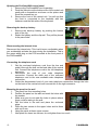
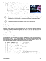
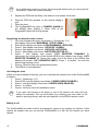
PROGUARD
800
PROGUARD800 SERIES
™
QUICK INSTALLATION GUIDE
ENGLISH
20213 / 20100604 • PROGUARD800TM ©
ALL RIGHTS RESERVED HAIBRAIN ®
Short installation manual
!!
If you follow the installation procedure mentioned below, you should not hear a
siren. Just to be sure, we recommend you to wear hearing protection during the
installation. This to prevent hearing impairment.
Quick installation of your ProGuard800 set
This manual is meant to install your ProGuard800 without having to read the regular
installation manual completely. Just the necessary operations are explained in this manual.
For safety warnings and a complete understanding of your ProGuard800 set please refer to
the installation- and user manual.
Requirements for the installation
x
x
x
x
x
x
Screwdriver, crosshead
Screwdriver, slot, blade size 0,6 x 5,0 mm
Screwdriver, slot, blade size 0,5 x 3,0 mm
Snap-off blade knife
Electric drill
Bit, stone 6 mm
Bit, metal 4 mm
Marker
ProGuard800 set consisting of:
x
Control panel
x
Motion sensor(MS845)
x
Keyfob remote control (KR814)
x
Door/window sensor (DS831)
x
Telephone cord with RJ11 Connectors
Installing the control panel
1
Do not install the wireless components yet!
Find the right place for your control panel
The ProGuard800 control panel should be placed inside in a room with adequate ventilation.
The panel should be accessible for maintenance and control.
Do not place the panel in rooms with a high atmospheric humidity or temperature, or where
the panel can get in contact with water or other fluids. Try to place the panel as centrally as
possible in the room that has to be guarded. Make sure there is a 230V and a telephone
connection (if you do not place a GSM800) close to the panel and do not place the panel
within 30 cm of the group box or large metal objects. This could adversely affect the range of
the wireless connections.
ProGuard800™
-2-
Opening the ProGuard800 control panel
1.
2.
3.
Remove the ProGuard800 from its packing.
Push the little pins at the bottom side of the central unit
gently with a screwdriver as shown on the picture and
move the screwdriver up.
Remove the front of the central unit. You will see that
the front is connected to the backside with two
fasteners and the flat-cable of the keyboard.
Removing the back-up battery
1.
2.
Remove the back-up battery by pushing the bottom
side of the clip.
Retain the battery and the clip well. They will be placed
in the panel later.
Disconnecting the internal siren
Disconnect the internal sire. This is a bit more comfortable when
you accidentally activate the siren during the installation. This is
the upper white plug on the PCB mounted at the front panel of
the ProGuard800.
Connecting the telephone cord
1.
2.
3.
Get the enclosed telephone cord from the box and
guide it through the hole on the back side of the central
unit. Connect the telephone cord to the left telephone
connector.
Disconnect the cord of your main telephone
connection. Connect the other end of the enclosed
telephone cord to the now available main telephone
connection.
Guide the disconnected cord of your main telephone connection through the hole
on the back of the central unit and connect this to the right connector.
Mounting the panel to the wall
1.
2.
3.
4.
5.
6.
7.
-3-
The panel has four mounting holes.
Position the panel on the wall and mark the holes with
the marker.
Make sure you do not mark the holes in places where
there could be wiring in the wall.
Drill the holes in the wall and place the enclosed
plugs.
Place the two screws in the upper holes and let them
stick out 5 mm.
Hang the panel at these upper screws.
Now place the lower two screws, do not tighten them too much.
© HAIBRAIN
Turning on ProGuard800 for the first time
1.
2.
3.
4.
1
1
Place the battery in the panel, but do not connect it yet.
Put the plug in the socket.
Because the tamper contact now is open, the panel
immediately generates an alarm warning. The siren is
disconnected, so the sound level is very low. Turn off
the alarm warning by typing 1 2 3 4 on the key board.
The display now shows: DISARMED SYSTEM
TROUBLE (it is normal for the panel to show this
notification). The red alarm indicator and the green
power supply indicator both flash.
Now connect the battery to the connector. Do not close the panel yet!
The green power supply indicator keeps on flashing until the battery is fully charged.
This takes about 24 hours. The red alarm indicator flashes because you triggered an
alarm warning. It stops flashing as soon as you activate the alarm system again.
The display now shows ProGuard800 and the not yet adjusted time.
Configuring the control panel
Control panel
When the control panel is in programming mode, the first line always indicates the subject.
The second line always indicates the options. With the / keys you can step through the
options. With 9 you can select or confirm what is stated on the bottom line and with 8 you
always go to a higher menu.
Setting the correct language
For programming the ProGuard800 you need an installation pin code. The default setting of
the installation code is 1111. Do not change this code until you are completely done
programming. When the panel is in programming mode and you do not press any keys, the
panel will automatically leave the programming mode after five minutes.
1.
2.
3.
4.
5.
6.
7.
8.
9.
10.
11.
12.
Press 9 followed by 1111.
Now enter 971 (the display now shows: SELECT DEF.).
Choose with till the display shows: DEF. EN XX.
Press 9.
The display shows: SELECT LANG.
Choose with till the display shows: ENGLISH.
Press 9.
The display shows: 1.INIT ALL. OK?.
Press 9.
The system will now restart with the English settings.
After a few seconds the display shows: DISARMED SYSTEM NOT READY.
After two minutes the display shows: PROGUARD800 and the not yet adjusted time.
ProGuard800™
-4-
Setting date and time
1.
2.
3.
4.
5.
Press 9 followed by 1111.
Press 7 99.
Now enter the correct time followed by 9.
Now enter the correct date followed by 9.
Press 8 3 times to leave the installation menu.
Switching off the siren
1.
2.
3.
4.
5.
Press 9 followed by 1111.
Now enter 9155 (the display shows: 5.WIRED SIREN ENABLED).
Now press (the display shows: 5.WIRED SIREN DISABLED).
Press 9 for confirmation.
Press 8 4 times to leave the installation menu.
The internal siren is still disconnected. You can now reconnect the plug of the internal siren
and attach the front of the central unit to the back using the hooks and then close the central
unit.
Registering of sensors
The ProGuard800 has 33 protected zones. Zones 1-32 are meant for wireless sensors.
Per zone 1 sensor can be registered. The Haibrain ProGuard800 supports various
wireless components like PIR sensors, magnet contacts and smoke detectors. Each zone
can be set to be a normal zone, or a zone with an entrance delay, or else. These zones are
factory set for various sensors by the manufacturer to make registering them very easy
for you. For an overview of the factory settings see the end of this installation manual. To
indicate that the ProGuard800 is still activated when you enter your house, it is
recommended to equip the entrance door with a Door/Window sensor with an
entrance delay. When entering the ProGuard800 indicates with sounds that the alarm is
still switched on.
You can now choose to install a Door/Window sensor with or without an entrance delay.
Registering a Door/Window sensor with entrance delay
1
Zones 1 and 2 are factory set for using a Door/Window sensor (DS831) with
entrance delay.
Programming
1.
2.
3.
4.
5.
6.
7.
8.
-5-
Go to the programming menu by pressing 9 followed by 1111.
(the display now shows: MAIN MENU 1.STOP COMM.).
Press 9 (the display now shows: 9.PROGRAMMING 1.DEVICES).
Press 9(the display now shows: 1.DEVICES 1.ZONES).
Press 9( the display now shows:1.ZONES ZONE #1).
Press 9( the display now shows:1.Z1 REGISTER TRANSMIT 1).
The ProGuard800 will now wait till the DS831 sends a signal.
Get the Door/Window sensor (DS831) from the box and open the housing by
sticking a screwdriver between the front and the back of the contact (near the
Haibrain logo at the bottom) and turning it.
Remove the red plate between the battery and the battery contact.
The ProGuard800 now makes a short beeping sound and the display shows: 1.Z1
REGISTER TRANSMIT 2. Wait for five seconds or push the sabotage contact and
you will again hear a short beep (the display now shows: 1.Z1 REGISTER SAVE?).
© HAIBRAIN
9. Press 9 to confirm. Now you will hear a long beep.
10. If you not wish to register any other sensors, press 8 5 times to leave the
programming menu.
11. The DS831 is now registered and is default set with an entrance delay of 30 sec.
12. Do not close the housing yet, hereafter in this manual you can learn how to place
the sensor.
Registering of a Door/Window sensor without entrance delay
1
1.
2.
3.
Zones 3 to 9 inclusive are factory set for the use of a DS831 without entrance
delay.
Follow the same routine as when reporting a Door/Window sensor WITH entrance
delay till you reached step four (the display now shows: 1.ZONES ZONE #1).
Choose with till the display says: 1.ZONES ZONE #3.
Now continue with step five (above).
Registering a movement detector
Opening MS845
1.
2.
Open the housing of the Motion sensor(MS845) by
removing the front. This is done easiest by sticking a
screwdriver in the unlock slot (at the bottom of the
detector, between front- and backside of the
sensor). Now move the screwdriver upward.
Supply the Motion sensor with power by removing the red plate which separates
the battery from the battery contacts.
1
Due to possible voltage delay in lithium batteries that have been stored, the
batteries might seem empty at first. When this happens, leave the sensor for
a few minutes till the voltage level is stabilised.
Programming
1
Zones 11 to 19 inclusive are factory set for using a MS845
If the ProGuard800 is still in programming mode after registering the door/window sensor,
then push 8 once (the display now shows: 1.ZONES ZONE #x). Follow the instructions from
step five (below).
If the ProGuard800 is not in programming mode, act as follows:
1.
2.
3.
4.
5.
6.
Log in to the programming menu by pressing 9, followed by 1111 (the display now
shows: MAIN MENU 1.STOP COMM.).
Press 9 (the display now shows: 9.PROGRAMMING 1.DEVICES).
Press 9 (the display now shows: 1.DEVICES 1.ZONES).
Press 9 (the display now shows: 1.ZONES ZONE #1).
Choose with till the display shows: 1.ZONES ZONE #11.
Press 9 (the display now shows: 1.Z11 REGISTER TRANSMIT 1).
ProGuard800™
-6-
7.
8.
Now press the tamper contact of the MS845.
The ProGuard800 now makes a short beeping sound
and the display shows: 1.Z11 REGISTER TRANSMIT
2. Now push the tamper contact again, you will again
hear a short beeping sound (the display now shows
1.Z11 REGISTER SAVE?).
9. Push 9 to confirm. You will now hear a long beeping
sound.
10. If you do not want to register any other sensors, push
8 5 times to leave the programming menu.
11. The MS845 is now registered and is default set without
entrance delay.
Testing of sensors
1
Should the reach of the ProGuard800 be inadequate, you can enlarge this with
the optionally available RP835 Repeater.
Test the chosen position of the central unit and the transmitters
When all transmitters are registered, we advice you to test the position of these transmitters
with regard to the central unit, before mounting it permanently. When you want to test the
signal strength of the transmitter, then use the transmitter test function.
To test the signal strength of the transmitter, do the following:
1. Log in to the programming menu by pressing 9, followed by 1111 (the display now
shows: MAIN MENU 1.STOP COMM.).
2. Enter 7072 (the display now shows: TX TEST).
3. Activate the transmitter you want to test (at the place you want to mount it) by
pushing the tamper contact or with the DS831 by moving the magnet from or to the
sensor or with the MS845 by generating some movement. The details of the
transmitter now appear on the LCD display of the central unit. Besides that you will
hear between 1 and 4 tones which indicate the strength of the received signal. 1
tone indicates signal strength 0-2, 2 tones indicate signal strength 3-5, 3 tones
indicate signal strength 6-8 and when you hear 4 tones the signal is at its strongest,
8-9, and that means the transmitter is at the best location possible.
4. You can leave the programming menu by pushing 8 4 times.
1
The MS845 Motion sensorsensor has a battery saving function; after every signal
transmission no more signals will be sent for four minutes. This makes your battery
last much longer.
Walk Test
With the Walk test, if you want to, you can check all reported sensors without causing an
alarm warning. This shows if all sensors are working properly.
To start the walk test:
1. Log in to the programming menu by pressing 9, followed by 1111 (the display now
shows: MAIN MENU 1.STOP COMM.).
2. Enter 706 (the display now shows: 6.WALK TEST ZONE #xx).
3. Activate every sensor by pushing the tamper contact or with the DS831 by moving
the magnet to or from the sensor or with the MS845 by generating some
movement; when the central unit receives a notification from the sensor, it
disappears from the list.
4. When all sensors have disappeared from the list, the display shows: End walk test.
-7-
© HAIBRAIN
Placing sensors
Placing the DS831
1.
2.
3.
4.
5.
The housing of the DS831 is still open after registering. If
you want to mount the housing with screws you have to
remove the PCB now. To remove the PCB you push the
PCB removal tab and carefully lift it from its holder.
Mount the back plate to the doorframe with the enclosed
countersunk head screws or double sided foam tape.
Make sure the line is pointed to the door.
If you have removed the PCB, now put it back by
carefully sliding it back into its housing and clicking it in
place.
When placing the magnet on the door, make sure that
the line of the magnet is placed at the same height as the
line of the sensor. If desired, you can turn the magnet
one quarter, like on the picture. By opening and closing
the door, you can see the LED light up, with the housing
open. When this is not the case, align the magnet more
precisely with the line of the sensor. Place the magnet on
the door using the two enclosed screws or the double
sided foam tape. If you use the screws, you can lift the
front of the housing with a small screwdriver. If
everything is placed properly, you can place the caps on
the magnet and the sensor.
The ProGuard800 has given a TAMPER ALARM for the
DS831 when placing it. Enter 1 2 3 4 on the Proguard800
when the caps have been replaced.
Placing the MS845
What to pay special attention to when picking a location?
x
Pick a location which is likely for a burglar to pass when he was to break into your
house.
x
Do not place any large objects in front of the detector.
x
Avoid a location close to a radiator, heating/cooling pipes, mirrors, air conditioners
and direct sunlight.
x
Choose an appropriate installation height of about two meters.
1.
2.
3.
4.
Remove the PCB by turning the Easy Lock to the left and remove it together with the
PCB – do not touch the surface of the pyrosensor!
Select two locations for screw holes in the housing and drill with a five mm drill to
open them. If the module is mounted flat against the wall, then use the lower two
holes (A). Is the sensor placed in a corner, then use two holes on the sides of the
sensor (B). You could also use the enclosed double sided foam tape.
Position the housing on the wall and mark the holes with a marker. Make sure you
do not mark the holes in places where there can be wiring in the wall.
Drill two holes at the marked places, place the plugs and attach the housing with the
two enclosed screws to the wall.
ProGuard800™
-8-
1
If you tighten the screws too much, the housing will deform and you cannot get the
lid back on. Fasten the screws manually.
5.
Replace the PCB with the Easy Lock and turn one quarter clock wise.
6.
Push the PCB fully upwards, so the vertical setting is
at 8
Place the front.
The ProGuard800 has given a TAMPER ALARM for
the MS845 when placing it. Enter 1234 at the
Proguard800 when the front is placed.
7.
8.
Registering the Keyfob remote control
1.
2.
3.
4.
5.
6.
7.
8.
Go to the programming menu by pressing 9 followed by 1111
(the display now shows: MAIN MENU 1.STOP COMM.).
Press 9 (the display now shows: 9.PROGRAMMING 1.DEVICES).
Press 9 (the display now shows: 1.DEVICES 1.ZONES).
Press (the display now shows: 1.DEVICES 2.KEYFOBS).
Press 9 (the display now shows: 2.KEYFOBS KEYFOB #1).
Press 9 (the display now shows: 1.KF1 REGISTER TRANSMIT 1).
Now press one of the keys of the keyfob (KR814) (the display now shows: 1.KF1
REGISTER TRANSMIT 2). Press once again one of the keys of the KR814 (the
display now shows: 1.KF1 REGISTER SAVE?). Press 9 to confirm. You will now
hear a long beeping sound.
Press 8 5 times to leave the programming menu.
The KR814 is now registered.
Activating the siren
When you have installed all sensors, you can re-activate the internal siren of the ProGuard800
if desired.
1. Press 9 followed by 1111
2. Press 9155 now (the display now shows: 5.WIRED SIREN DISABLED).
3. Press now (the display now shows: 5.WIRED SIREN ENABLED).
4. Press 9 to confirm.
5. Press 8 4 times to leave the installation menu.
1
If you open the housing of the panel or one of the sensors, the siren will now
always be activated. You can de-activate it by entering your user code on the
panel or pressing the key with the open padlock on the KR814 remote control.
Making a call
The ProGuard800 can make a call to an emergency centre or any number you choose. In this
manual we explain how you can set the ProGuard800 so it will call the number you have
chosen.
-9-
© HAIBRAIN
Setting a private number
1.
2.
3.
4.
5.
6.
7.
8.
Log in to the programming menu by pressing 9 followed by 1111 (the display now
shows: MAIN MENU 1.STOP COMM.).
Press 9 (the display now shows: 9.PROGRAMMING 1.DEVICES).
Press 5 (the display now shows 5.COMMUNICATIONS 1.ACCOUNTS).
Press 9 (the display now shows: 1.ACCOUNTS 1.CS ACCOUNT 1).
Press 4 (the display now shows: 4.VM ACCOUNT 1 1.PHONE NUMBER).
Press 9 (the display now shows: 1.PHONE NUMBER).
Enter the telephone number that has to be called followed by 9.
The other settings are all right at the moment. You can leave the programming
menu by pressing 8 6 times.
Testing a private number
The ProGuard800 is set to call the number you entered when a problem or alarm warning
occurs. This number will also be used to announce whether the alarm is switched on or off.
We are now going to use this option to test if it is functioning properly.
1
Make sure nobody walks past the MS845 during the test! An alarm warning would
also be generated immediately.
Activate the alarm system by pressing the key with the closed padlock on your Keyfob remote
control (KR814).
You will hear a voice saying: “full arming” and the timer for the exit delay will start running.
This will last for about 60 seconds. The display now shows: FULL ARMING XX TO EXIT.
After 60 seconds you will hear the notification “system armed” followed by a number of tones.
The ProGuard800 is now making a call.
If you pick up the telephone that is being called, you will hear the following notification:
“ProGuard800 alarm system, system armed. For the next message, press 1”. This notification
keeps repeating itself until you press 1 on your telephone. You will now hear “no further
messages” and the connection will be terminated.
You can switch off the alarm system by pushing the open padlock button on your KR814. The
ProGuard800 will confirm this with the announcement “system disarmed”. Also, an immediate
call will be made. If you answer this call you will hear: “ProGuard800 alarm system, system
disarmed. For the next message, press 1”. This notification keeps repeating itself until you
press 1 on your telephone. You will now hear “no further messages” and the connection will
be terminated. If you do not push 1, the connection will be terminated after a little while and
you will be called again, or a second number will be called if this is programmed.
Shutting off the announcement that the alarm system is switched on or off
If you don’t want the programmed telephone number to be called every time the alarm system
is switched on or off, you can switch off this option as follows:
Log in to the programming menu by pressing 9, followed by 1111 (the display now
shows: MAIN MENU 1.STOP COMM.).
2. Push 9 (the display now shows: 9.PROGRAMMING 1.DEVICES).
3. Push 5 (the display now shows: 5.COMMUNICATIONS 1.ACCOUNTS).
4. With you can step through the menu, till you reached step six or just press six
(the display now shows: 5.COMMUNICATIONS 6.VM EVENT OPT.).
ProGuard800™
- 10 1.
Press 9 (the display now shows 6.VM EVENT OPT. 1.BURGLARY).
With the / keys you can step through all events and with 9 confirm your choice.
( 6 is activating, 7 is deactivating) You could also enter the number of your choice
directly, followed by 9. The display now shows for instance: 6.ARM ENABLED.
With the key you can change this into DISARMED and confirm with 9. This way
you can enter your preferences for every spoken announcement.
5.
6.
Entrance codes
The ProGuard800 has several entrance codes for the various ways of use. You already know
two codes. Code 1111 for programming your ProGuard800 and code 1234 as Master code for
the user. Change these codes into your own codes after getting acquainted with the system.
Adding a user code
To add a code for your housemates who should be able to shut off the alarm system, you act
as follows:
1. Log in to the programming menu by pressing 9, followed by 1234 (the display now
shows: MAIN MENU 1.STOP COMM.).
2. Press 4 (the display now shows: 4.USER CODES).
3. Press 20 (the display now shows: 4.USER CODES USER 20 NON_CTRL).
4. Press 9 (the display now shows: USER 20 NON_CTRL 1.EDIT CODE).
5. Press 9 (the display now shows: 1.EDIT CODE 0000).
The cursor is located at the first number. Change the code into a code not used
before.
Push 9 to save the new code.
You can leave the programming menu by pushing 8 3 times.
6.
7.
8.
1
If you enter a code which matches an already existing code, the central unit will give
an error message by means of a tone. The new code will not be saved. 0000 is not a
valid user code. You can use this for removing a user code.
Code 1-29 can only be changed with the Master code. The installer’s code, guard
code and emergency room code can only be changed by the installer.
ProGuard800 display and status Indicators
System status indicators
The system status indicators inform you about the status of the system
like alarm ON, alarm OFF and electricity failure.
If the Armed LED
is…±
It means…
Off
The system is disarmed.
On
The system is armed.
Flashing
An alarm has occurred. Alarm indication is cleared the next time that an
arming sequence is initiated or after the relevant event has been viewed in
the event log.
Table 3.1: Alarm status indicators
-11-
© HAIBRAIN
1
The alarm warning does not appear on the display when a panic alarm is triggered.
If the Power LED is… a
It means…
Off
Both AC and Battery power are disconnected.
On
System Power is OK.
Flashing (slow)
Backup battery low or low battery from transmitters.
Flashing (fast)
AC loss.
Table 3.2: Power supply status Indicators
Arm Status Display
The Arm Status Display contains the current status of the display and possible error
messages in the system. You can choose whether you want to see this information
continuously or just for two minutes after switching the system on or off. By default this is set
for two minutes after switching the system on or off, so when someone is breaking into your
house he cannot see whether the ProGuard800 alarm system is switched on or off, and so the
system is able to sound a “silent alarm”.
To set the Arm Status Display to display always:
1. Log in to the programming menu by pressing 9 followed by 1111 (the display now
shows: MAIN MENU 1.STOP COMM.).
2. Press 94061 (the display now shows: 6.DISPLAY 1. ARM STATUS).
3. Press 9
4. Press (the display now shows: 1. ARM STATUS DISPLAY ALWAYS).
5. Press 9
6. You can leave the programming menu by pushing 8 5 times.
RP Pass code
The RP (remote programming) pass code is a six character code which allows remote
programming. When a RP connection is established, the programmed RP pass code on the PC
should be the same as the RP pass code of the central unit. The default RP pass code is 123456.
We advice you to change this code in your own unique code immediately.
To change the RP Pass code:
1. Log in to the programming menu by pressing 9 followed by 1111 (the display now
shows: MAIN MENU 1.STOP COMM.).
2. Enter 9522 (the display now shows: 2.RP PASSCODE 123456).
3. Enter six characters.
4. Push 9 when you are done changing.
You have now configured the basic settings of your ProGuard800 set. We refer to your
installation manual for further configuration possibilities of your ProGuard800 and to your user
manual for the daily use of your ProGuard800.
ProGuard800™
- 12 -
Important default settings
User codes
You can program up to 32 different user codes in to your ProGuard800 system. A user code
has four numbers. For most system functionalities you have to enter your user code.
User
Code
USER 1 MASTER
1234
USER 32 INSTALL.
1111
Zones
The ProGuard800 has 33 safe zones. Zones 1-32 are meant for wireless sensors. Per zone
one sensor can be registered.
Zone
Type
Descriptor
1 to 2
ENTRY/EXIT
DS831
3 to 9
NORMAL
DS831
11 to19
NORMAL
MS845
21 to 22
FIRE
SD833
23 to 24
FLOOD
WD861
25 to 26
24 HOURS
TS863
Keyfobs
Two kinds of Keyfob transmitters can be registered to your ProGuard800, the PR811 and the
KR814. You can register up to 19 Keyfobs to the system.
KR814 KEYFOB #1 to #10
PR811 KEYFOB #11 to 19
Keypads
The ProGuard800 can be operated with at most four wireless keypads. Except for the cancel
button the operation of the WK820 and the RC840 keypads is the same.
RC840 KEYPAD #1 to #2
WK820 KEYPAD #3 to #4
ProGuard800™
- 14 -
Entrance/exit delay
The entrance/exit delay shows how much time the user has to activate or deactivate the
system before an alarm warning is generated.
92
2.ENTRY/EXIT
9 1.EXIT DELAYS
9 1.EXIT FULL
60
9
d 2.EXIT PART
60
9
d 3.EXIT PERIMETER
60
9
9 1.ENTRY FULL
30
9
d 2.ENTRY PART
30
9
d 3.ENTRY PERIM.
30
9
d 3.ARM ON EXIT
9
ENABLED
9 d 4.SUPP.ENT.DELAY
9
DISABLED
9
d 5.ENT. DEVIATION
9
DISABLED
9
d 6.EXIT RESTART
9
DISABLED
9
d 2.ENTRY DELAYS
Communication
4.VM ACCOUNT 1 to 3
5.EVENT
OPTIONS
-15-
91.PHONE NUMBER
9
9
2.INTERFACE
9 PSTN
9
3.TWO-WAY AUDIO
9 ENABLED
9 1.BURGLARY
d 2.FIRE
d 3.OPEN/CLOSE
91.RAPPORTAGE
d2.RAPPORT HERST.
d3.TWO-WAY AUDIO
91.RAPPORTAGE
d2.RAPPORT HERST.
d3.TWO-WAY AUDIO
91.RAPPORTAGE
d2.RAPPORT HERST.
91.RAPPORTAGE
d 4.SERVICE
d2.RAPPORT HERST.
d 5.POWER
91.RAPPORTAGE
d2.RAPPORT HERST.
d 6.PERIPHERALS 91.RAPPORTAGE
d2.RAPPORT HERST.
91.RAPPORTAGE
d 7.RF JAMMING
d2.RAPPORT HERST.
d 8.MEDICAL
91.RAPPORTAGE
d2.RAPPORT HERST.
d3.TWO-WAY AUDIO
9ENABLED
9ENABLED
9ENABLED
9ENABLED
9ENABLED
9DISABLED
9ENABLED
9ENABLED
9DISABLED
9DISABLED
9DISABLED
9DISABLED
9DISABLED
9DISABLED
9DISABLED
9DISABLED
9ENABLED
9ENABLED
9DISABLED
9
9
9
9
9
9
9
9
9
9
9
9
9
9
9
9
9
9
9
© HAIBRAIN
Home Control modules
The Haibrain ProGuard800 supports the X-10 protocol. With this you can integrate a broad
range of Home Control products in your Alarm system.
9 1.HA UNIT#1
1.HA UNITS
d 2.HA UNIT#2
91.ON TIME #1
900:00
9
d2.OFF TIME #1
900:00
9
d3.SCHEDULE #1
9······· 1=S,2=M
9
d4.ON BY ZONE#1
900-00
9
d5.ON BY ARM #1
9DISABLED
9
d6.ON BY ALARM#1
9ENABLED
9
d7.KF CTRL .#1
9DISABLED
9
d8.TEL. CTRL #1
9DISABLED
9
d9.RANDOMIZE #1
9DISABLED
9
d10.PULSE TIME#1
9
d11.DESCRIPT. #1
92 MIN.
APPLIANCE
9MODULE
91.ON TIME #2
900:00
9
d2.OFF TIME #2
900:00
9
d3.SCHEDULE #2
9······· 1=S,2=M
9
d4.ON BY ZONE#2
900-00
9
d5.ON BY ARM #2
9DISABLED
9
d6.ON BY ALARM#2
9ENABLED
9
d7.KF CTRL .#2
9DISABLED
9
d8.TEL. CTRL #2
9DISABLED
9
d9.RANDOMIZE #2
9DISABLED
9
d10.PULSE TIME#2
92 MIN.
DIMMER
9MODULE
9
d11.DESCRIPT. #2
2.HOUSE CODE
9A HOUSE CODE
3.HA CONTROL
9ENABLED
1
9
9
If you make any changes in the ProGuard800 it will be very useful to write
down these changes. To help you with this, you can download a form from the
Haibrain website with all the default settings already filled in.
Copyrights
Copyright and all other proprietary rights in the content (including but not limited to model numbers, software, audio, video, text
and photographs) rests with Haibrain B.V. Any use of the Content, but without limitation, distribution, reproduction, modification,
display or transmission without the prior written consent of Haibrain is strictly prohibited. All copyright and other proprietary notices
shall be retained on all reproductions.
ProGuard800™
- 16 -
ZI0488B (1-09)