1
?IAXION??
USERMANUAL
i
AXTON Owners Manual
CONTENTS:
Introduction and Product Oveliew
1.0 The Chassissystern- description
1.1 The chassissystern
2.0 The Master section - description
2.t Solo section
2.2 CRM section
2 .3 Cornrnurricationsection
2.4 Rec.outAlternative P.A. section
2.5 Two track replay section.
2.6 Oscillator section
2.7 Mute CPU section
2.8 Auxilli"ry rnasteroutput section
2.9 VCA Grarrdrnastersection
3.0 The "Inputtn module - description
3.1
3.2
3.3
3.4
3.5
3.6
3.7
Channel assign section
The input section
The Equalizet section
The Auxilliairy section
The Solo rnute section
The fader/VcA section
Input rnodule in and ouput connectots
4.0 The *Stereo module)' - description
4.L Channel assign section
4.2 Balanee I stereo width section I Crain section
4.3 Crain section
4,4 EQ section
4.5
4.6
4.7
4.8
The Aux section
The solo/ Mute section
The fader I VCA section
Channel / meters
5.0 The *Group IMatrix/ VCA ))- description
5. 1 Matrix input section
5.2 Group output section
5.3 VCA master section
6.0 Instructions for operation
7.0 Installation - electrical
8.0 fnstallation - audio
8. 1 Interface rnonitor
8.2 The initial hook - up
8.3 Shielding and grounding
8.4 Typt"al interface table
8.5 Master sectionrnodule connectots
8.6 Connecting / configuring of the channel module
8.7 lurnper settings on the channel
8.8 Jurnpersettings on the stereochannel
8.9 Jurnpersetting* on the group / rnatrix rnodule
8.10 Jurnpersettrngson the rnasterrnodules
9.0 Linking of two or more consoles
10.0 Thoubleshooting
10. 1 Rernoving arnodule
Deat client
Thankyou for selecting the D&R Axion series.
The Axion was cteated using the latest in computet aided design
and assembling technology and incorporates the most advancedcitcuit components which rcsults in the Axion being another D&R
product unsulpassedin the electrcnics indusffy.
We ate confident that you will be using tlre Axion fot many years
and wish you much success.
We always value suggestiorrsfiom our clients and we would be
gtateful if you could comflete and retum the questionaire included
at the back of this manual once you become farniliar with your
Axion. We learn ftomyout comments and appreciateyour time.
With kind regards,
D- de Rijk
President,D&R Electronicab.v.
AXIOhI soundreinforcement
Console
The D&R Axion series is a balanced 8 buss Ftont Of House
(FOH) soundreinforcementmixing console designed to take the
central rcle in a life performance facility.
The Axion is completely modular and can be configured to precisely zuit your pafiicular system requirements.
To become completely familiar with your Axion and gain the maximum benefit from its use, \ile recornmend that you tead this manual thoroughly. It will ptovide impottatrt inforrnation about all
aspectsof the Axion including; installation, qleration, and setvicing.
Ilead Office / Factory
D&R Elecffonica B.V.
Rijnkade 158
L382 GS Weesp
The Netherlands
Tel: (-) 31 2940 18014
Fax: (-) 31 2940 16987
U.S.A. Office
D&R I.T.S.A.
Rt. 3, Box 184-4
Montgomery, TX 77356
Lr.s.A.
Tel: (409) 583-3411
Fax: (409) 588-3299
THE CHASSISSYSTEM
1.0 The ChassisSystem
The Axion is available in two frarne sizesoaccepting44 and 60 input rnodules.The basic frarne includes five blank rnodules,two
are located on the extrerne left and right of the frarne and two rnore
are on the left and right of the master sectior, and there is one
rnore right frorn the group rnafrix rnodules. The extrerneleft and
right blanks cannot be used for input rnodules as they conceal rnechanical constructions, wiring, and power distribution, as is the
casewith the blank right of the rnastersectiotr.However the blank
on the left side of the rnaster section and the right side of the group
maffix rnodules can b" r*placed with input rnodules if visual seperation of rnaster and group rnodules is not requested,in this case
the frames can accept 46 and 62 rnodules.
The frarne 44 will fit 44 input rnodules (32 input and 12 stereornodules), 6 rnasterrnodules, and I group/rnafrix tnodules.
The standardconfiguation has (from left to right) 1 blind rnodule,
32 input rnodules, 1 blind rnodule, 6 master rnodules, 1 blind rnodule, 8 group/rnatrix rnodules, 1 blind rnodule, 12 stereornodules
and 1 blind rnodule. Custorn configurations ete available at no extra charge.
The frarne 6Owill fit 6Oinput rnodules (48 input and 12 stereornodules), 6 rnasterrnodulesoand 8 group/rnatrix rnodules.
The standardconfiguation has (frorn left to right) 1 blind rnodule,
24 input rnodules, 1 blind rnodule, 6 master rndules, 1 blind module, 8 grouplmatrix rnodules, 1 blind rnodule,24 input rnodules,
12 stereoinput rnodules, 1 blind rnodule. Custorn configurations
are available at no extra charge.
Both the rnaster section and group/rnaffix rnodules can be installed
wherever rnost zuitable, but the requestrnust be rnade at the time
of ordering.
THE MASTER MOI}ULES
The Axion has six rnasterrnodules which are cornpletely modular.
A11inputs and outputs are located on the back of the rneter bridge.
The paruEraphsbelow gtve a description of eachrnodule sectiorl.
2.1 Solo section
The Solo section has a master PFL volume corrtrol with a center detent fot nominal levels and a master AFL volume control with a
cenhe detent and a Channel to Solo In Place switch with a switchcover to prevent fiom accidental switching dwing life performanoes.When this switch is in the up pmition, all solo switches on
the input modules are in the *PFL" mode when activated. A LED
indicator is also fitted next to the PFL level control to show when a
solo circuit is activated. Both AFL and PFL controls have a range
of + and - 20 dB.
2.ZTheMOMTOR section
The Monitor section contains the electronics fotmonitoring all signal paths in the Axion.
Monitor Source switching
Frorn the top of this sectionothere ate the five Monitor signal sources. With all theseswitches in the up position, the Monitor will not
receive any input signal. This has been d*rtgned to be able to listen
to any cornbination of input sorrce switching as is desired during
perforrnances.
The first switch activatesthe Listen rnicrophone fed firrrn a seperate rnic input at the back of the console. This rnic input can be used
for checking sound in the auditoriurn of a theatre where seperate
control roorns at€ used for the rnixing console. The listen Mic input can b* phantorn powered by juroper settings on the printed circuit board.
The secondand third switch rnake it possible to listen to 2 track inputs frorn CD players.
The fourth switch lets you check the Mono output of the console
and the fifth switch checks out the stereornain outputs, post rnain
faders.
The last switch lets you rnonitor pre or post the rnain rnono/stereo
faders. Now it is possible to check the rnain rnix without sending
signal to the speakersysterns.Al1 selectedinput sourcescan be
surnrned.
The monitor control has a sepetateoutput for nearfield monitoring. The Phones control has its own outputs on the frontpanel in a
t'ecessedsection close to the faders. A mute switch cuts the very powerfull headphonesamps.
The main stereo faders afe mono audiotapr faders and control the
overall outgoing level coming from the main stereo mix bussamps.
A 10 dB gain is available at the output which is set to be +4dBu
nominal.
Monitor level
The Monitot level controls the total outgoing level to the monitot.
of +4 dBu is
When in the full cloclapise positiorr, a balanced
glven out to the monitot amps. It is important to"igtul
have the monitot
arnps correctly adjusted. You should adjust the monitor amps (input level controls) to an undistorted level with the Monitot level
control fully clochvise.
NOTE: This alignment is imperative in order to avoid dnmage to
the speakers, or in some cases,damage to the ears of the listener.
T\vo monitor Systems
The Axion has two monitorsystetns intended foruse with headphones and nearfield monitors. V/e advise that nearfield monitors be
wired to the Monitor output.
Insert stereo
The insefi switch switches the signal processorsretums into the
main signal path for both left and dght outputs.
2.3 COMMT]NICATION SECTION
The cornnrunication section is a very cornprehensiveand irnportarrt
part of the Axion console. It is vital in life perforrnancesto be able
to cornrnunicate at arty point during the showhrside the rnastersection of the Axion there is a "Clearcorn"
*ASL" cornpatible rnasterstation to feed *Beltpack" systernsof
either bmrrdornaking coil]rnunication easy.
The Talkback rnicrophone (which has an input on the frontpanel
as well as on the connector panel at the back of the console) can be
phantorn powered by j,rtoper settings on the board.
The Talkback rnic can be assignedto the following sections of the
console individually or to all at the sarnetirne.
Direct output at the back of the console.
Aux ouput arnps (if the aux enable switches are active)
Matrix outputs ( if the aux enableswitches are active)
Group outputs (if the group enable switches are active)
Mono output
Stereooutput
Communications to phones
This switch brings the cornrmrrication systern into the phones to be
able to listen to stageengtneerscalling you through their
"beltpacks"
Phonesto communications
This switch allows you to pass the rnonitor signal to the beltpacks.
Stage englneers can pre fade listen to channels and have the sarne
acces to all relevant signal irnloutputs in the console as the rnain balance engrneef.
Side tone
These trirnrners allow you to reduce the send signal in the cornrnunication systerns tn be lower than the receive signal. This needs to
b* .djusted once depending upon how many "Beltpacks" are connected to the systern.
Comm
This switch assigns the talkback rnic signal to the cotffnunication
qystern only.
Call uL" l$R)?
These switches activate the optical call system with a flashing light
on all connected Beltpacks when hit once, after holding down the
call buffons a few seconds a sirene will start drawing attention
when the "called" station has not answered"
Insert mono
This switch switches the return of a connectedsignal processor
into the mono signat path.
2.4 RECORI) OUT / AUr P.A.
This section provides you with a second stereo output from the
Axion's nlaster section. It can be fed frorn the either the stero output or the rnono output. Both these srgnals can be taken pre or post
the rnain faders. Arl AIIL switch checks out the signal strength and
sorrcing.
2.5TWOTRACKREPLAY.
The Axion has a seperatetwo track replay input with lineair fader
and a two band equalizet.
Both 2 track A and B can be sumrned if necessaryand send to the
rnono and or stereornain outputs. The stereofader sendsthe 2
track signals post rnain faders directly into the stereoand/or rnono
output arnps. Smooth fading in and out of 2 track and lor rnain
rnix buss sound is easily achieved.
2.6 OSCNTATORSECTION
A sweeposcillator is fitted. The sweepfrequencies are;Z0Hzto
Zl<tlz,ffid 200Hzto 20kHz.1he level rangesfrorn -35 dB ta +2O
dB with a detentedrnid-p*ition of +4 dBu. The oscillator can be
switched to pink noise to be able to check out frequency response
of the auditorium.
The oscillator can be routed to the aux mix busses,group busses,
mono output, Ieft output only, right output only, and to a direct
output.
NOTE: The rnonitor will dim 20dB when the oscillator is active.
The rneters on the Axion are peak reading rneters and therefore
read +4 dB when a sine wave with a +4 dB outtrrutlevel is sent to
the rneter. Measuring the +4 dBu output level of the channel or
rnasterwith a AC voltrneter would grve a I .22 volt reading.
2.7MUTECPU SECTION
The Axion has the possibility to store/prograrnrnute settings in the
charrnels to a rnaxirnurn of 64 settings.
The RESET switch resets the CPU to a start position without era*ing rnute settings in the channels.
The SAFE switch prevents the cornputer frorn being activated.
The MIDI switch changes the diupluy frorn displaying patches into
rnidi channels
NOTE: THE MIDI SOFTWARE IS NOT YET IMPLEMENTED,
BUTWILL BE SOON BY A *ROM''UPDATE.
The CHANNELPATCH switch letsyou changethe display frorn
showing the rnidichannel nurnbers into showing the patch nurnbers
used for storing rnute patches.
The display seffes different rnodeswhich will be explained later.
The STORE switch lets you store mute settingsfrorn the channels
against a patch number.
The UP/DOWN switches let you step up and down through the 64
available patchnurnbere.
The PREVIEW switch shows the stored rnute setting under the displayed nurnber by flashing the channel mute larnps, without changrng the actual rnute settings.
The RECALL switch activates the rnute setting stored under the
actual display nurnber showed at that rnornent.
The A to H switches can be used to store 8 settings out of the 64
patchesto be able to instantly recall a stored setting.
To use the Mute CPU it is advisable to follow the next instructions.
When the Mute cornputer is "ernpty" ( does not have prograrnrned
rnute settings) it is advisable to set the disply to OO (rnax 63) by
hitting the up or down switches. Longer pushing of the up/down
switches will causethe diryluy to run faster after a while.
Now prograrn the necessary rnutes in the channelsand hit the STORE switch, which will store this setting under patch nurnber OO.As
soon as this patch is stored the display will show patch O1which
will be your next patch available for storing new tnute settings
from the channels.This sequencecanbe repeatedup to setting 63
to achieve a firaxirnurn of 64 different patches.
To RECALL patchessirnply choosethe patchnurnberby the
upldown switches and hit the recall switch to activate that patchnurnber.The recall switch will be lit now. As soon as you change the patch settings to another patch in the display the RECALL
buffon lurttp will turn off showing you that the display setting is
not the actual channel rnute setting.
The Preview firnction now shows the new dirpluy rnute setting by
flashing the related rnutes in the channel. THIS WILL NOT CHANGE MUTE SETTINGS!
To store a str)ecificrnute setting under one of the 8 large recall switches A to H, sirnply hit the store switch and assign this setting by
holding the store switch down followed by pushrng the requested
A to H recall switch.
2.8 AUXILLIARY MASTER SECTIOhI
All auxilliary rnastersections areidentical in function. All sections
have level corrtrol, a talkback enable switch, an AFL switch, a
Mute switch and a globul pr*lpost switch.
Each Aux rnastercontrols the bussesfrorn the channels. The solo
switch sendsthe aux buss signal to the rnonitors which is a post-fader signal. The associatedLED lights indicating the activated solo
switch.
The Aux rnute doesnot rnute the signal sent to the AIIL buss, but
rnutesthe outgoing signd to the aux outputs only.
The global prehost switching in the Axion console is a convenient
way of globully switching the pre/post feed of one aux buss for the
entire console.
Aux L lzand 3l4ateswitchedgloballyin pairs.Aux5to L2are
switched individually pre/post per aux bus.
2.9 Y C AGRANDMASIER SECTION
The grand mastet fader controls all assigned group VCA masters
with an extra gain of LOdBover the goup VCA master.
Idastet Metering
The Axion master is fitted with peak reading, high resolution, LEDbar meters with attack and rcleasetimes which conform to world
standards.The attack is l0msec. fot a2O dB range and the nelease
is 1.5msec.Thepeak reading ledbars will show 50 dB of dynarnic
range from -30 to +20d8. This enorneous range precisely tells
you what the actual headroom is that is available at any tirne.
The Axion has seperatemeters for PFL and stereo AFL as well as
stereo monitor.
The rnain lef{right outputs are displayed on VtI type meters to
give an averagelevel. The mono output is diplayed in VU on a ledbar, and the PFLIAFL and rnonitor signals are displayed on pealcreuding ledbars. The actual level displayed on the pea*reading
ledbars is the internal level of the console at that specific point.
There is no 6dB down adjusfinent on the ledbars in the Axion. We
did not want to createany doughts about the available headroom in
the console.
If analog meters are mounted, when reading o0" on the W meter you should have a +4 dBu or 7.22 volts on a vok / ohm tneten
THEII\PUT MOI}ULE
3.0 THE INPUT MODULE DESCRIPTION
The Axion input module is a basic input design whereby all signal
flow takes place ftom the micmphone to the main outputs. Each
input channel is shipped with a 25 segment LED bargraph meter
which is a peak teading device with attack and rclease times in conformance with world standards. It reads the level atfour points in
the channel. At the pre insert point, at the post insert point, at the
post EQ point, and at the post VCA point. The first LED in the
bargaph is a power supply indicator. The following sections explain the rnany functions and features of the input channel.
3.1 CHAhINEL ASSIGN SECTION
The channel assign switches are .located at the top of the rnodule
and send the signal to the 8 groups individually or to any cornbination of this. Assigrnent to the leftltight bussesand to a seperate
fnono output is possible.
The pan-pot can be inserted between the odd and even groups
when necessary.fJre pan-pot is always active on the Leftlnght buSES
3.2THEINPUTSECTION
The input section controls all incorning signals frorn rnicrophone
and line inputs.
The GROUND-LIFT switch lifts pinl frorn the )ftR type rnic input connector frorn grorrnd.
A +48V phantorn power switch for condenserrnicrophones or direct boxes can be switched in or out of the circuit.
NOTE: IT ISADVISABLE TO HAVE THE CHANNEL MUTED
WHEN SWITCHING INOROUTTHE PHANTOM POWER!
The ground lift switch is autornatically disabled when the phantorn
power is switched orr.
The groundlift LED will turn off accordingly.
Line switches the microphone input to line input on the channel.
The line input has its own balanced input amp and is corrtrolled by
the active (dual) gain contnol.
The GAIN control is the single most important conttol on the console. With this corrtrol accumtely set, it is possible to achieve the
very best signal to noise tatio and maximum headroom tequired
for high quahty life sound. This conmol is for adjusting the line /
mic input and has seperateelectronics although only one lcrob adjusts the dual pot.
Phase is used to leverse the phase of any mike / line input coming
from a mike or signal that may be out of phasewith other rnikes or
signals. A successfulmethod of checking for *out of phase" signals is to pan both signals to the centre and llisten closely to the
mix. If an unexpected sound is heard or if something appearsto be
missing ftom the mix, depressthe phaseswitches for those channels suspectedto be in error. If the sound improves, then that channel was out of phase with the others.
If using multiple mikes on the samesignal, such as drums, vocals,
homs, sftings etc., it is possible to create an acoustical phase cancellation. In rnost cases,physically moving the mikes a few inches
will correct this phase cancellation.
3.3 THE EQU LLIZER SECTTON
Just aheadthe equalizet section there is a variable 12 dB VCVS
high passfilter with a Butterworth cunre rarrging ftorn 2OHz to
IWIz switchable in or out of the circuit independant of equalizer
on/off switching.
The four-band pararnetricequallzer is unique in its design. There
are four bands, the high and low are sweepablefrequency with
shelving characteristicswith a boost or cut of 16 dB and the two
rnid bands each sweepablewith a boost or cut of 16 dB. The HMF
(High / I\fid Frequency)and LMF (Low 1tvfid Frequency)can be
switched to a nalrower bandwidth frorn Ll3 to 2 octaves.
The HF (htgh frequency) section is a variable frequency shelving
type sweepablefrorn 2,000 Hz to 20,000 Hz with a rnaxirnurn
boost or cut of 16 dB.
The LF (ow frequency) section is a varible frequency shelving
type sweepablefrorn 2OHz to 500 Hz with a rnaxirnurn boost crr
cut of 16 dB.
The HMF (High / Mid Freq.) section has level and frequency conttols and is a constant Q type, therefore the bandwidth setting will
rnatch that of the level control. The frequency rangesftorn 5OOHz
to 10,000 Hz and has a rnaxirnun boost or cut of 16 dB. The
bandwidth is switchable between Ll3 and 2 octaves.
The LMF (Low / I\fid Fteq.) section has level and ftequency controls and is also a constant Q type, therefore the bandwidth sefting
willmarch that of the level control. The frequency ranges from
50 Hz to 1000 Hz and has a maximurn boost or cut of 16 dB. The
bandwidth is switchable between Il3 md 2 octaves.
All level controls are center detentedmaking neutral pmitions easy
to establish.
All ftequency rangeshave been canefully selected following extensive examination of all types of music which makes this equalizer
a pleasure to work with. Noise and distottion are kept to an absolute minimum.
3.4 AUXILTIARY SENDSECTION
The Axion has twelve auxilliary send busses. Auxilli*ry sends
I&2 and 3&4 are on dual concentric controls. The top control is
the send control for aux 1 and 3 and the bottorn control is the send
for aux 2 and 4. TheseAux bussesare norrnally used for stereo
headphonesends. All four can be fed frorn either pre or post the
channel fader by the global pre/post switching in the rnaster aux
sections.
Aux 5 to l?have individual globul pr*lpost switching per buss located in the rnaster sectioll.
All aux sendshave individrral rnutes per send except for aux Llz
and 314.
Aux 12 has a direct switch redirecting the aux buss 12 signal to a
dedicatedoutput on the back of the console. This output can be
used for life tracking of individual channels,or as an aux send for
a specific channel.
3.5 THE SOIJOMUTE SECTION
*deThe SOLO switch has two modes, pfl (pr fade listen) or a
structive" stereo Solo-In-Place system. Master stafus switching
(ocated in the mastef section) selectsthe "Solo In-Place" or *PFL"
rnode for the entire console.
Activating the solo switch in the pflmode will send the prefader
of the rnonitor section to the monitor/headphone outputs. In
"igtul
the solo in-place mode, atl assignedsignals in that channels post fader is heand,and all other channels ale muted within the stereo
rnix. A solo indicator LED is fitted next to the solo switch. The
SAFE switches in the channel prevent the SIP system from muting
the channel.
The SAFE switch also ptevent the mute computer ftom controlling
the mute status of the channel. The MUIE lamp will have a higher
intensity when both the SAFE switch and MUTE switch is activated to indicate that local muting is active.
The peak led in the channelrnodulernonitors signal level on 4
points in the channel.
The MUTE ry"tern is a special soft-muting systerncontrolled
either by the local rnute switch or by the rnute cornputer located in
the master section. Low intensity rnuting will indicate that the
rnute function can be controlled by the rnute cornputer. The SAI1E
switch prevents the rnute being controlled by the rnute computer.
3.6 THE EAI}ER VCA SECTION
The Axion has a high quality l00rnrn ALPS fader, P&G faders are
optionally available. The lineair fader controls a high quahty dbx
VCA which in turn can be controlled by . group rnasterfader, if
the channel is assignedto such a fader.
Assignment of the channel VCA fader is as follows.
By hitting the *VCA" select switch once, one of the led indicators
1-8 will light, indicating which VCA rnasteris selected.By hitting
the VCA selectagain the next in nurnber VCA will be selected.ff
vca rnaster8 is o[, the next selectionwill be vca nr 1 and so on. If
you wish to de-selecta channel frorn a vca rnaster,sirnply push the
select switch for rnore than 1 secondand the assignswitch will
turn off indicating that the local fader has been selectedfor VCA
control.
NOTE: the VCA rnax led indicates whether there is still gain left
in the vca. If the VCA is corrtrolled by r rnasterVCA, it is very
easy to "overload" the VCA by bringlng up the rnasterVCA fader
above 0 dB, lets say to +5d8. If the channel VCA fader is already
set to +5dB the rnaxirnurngain of 10dB is already given away, and
no exffa gain could be expectedfrorn the VCA, even when the
channel fader indicates a further 5 dB of frontpnel gain.
CHANNELMETERS
The Axion is shipped wirh25 segrnentledbar rnetersin the standard configuation. The first LED in the bargraph is a power supply
indicator.
3.7INPUTMOI}ULEIN Ah[I} OUTPUT
CONNECTORS
Every charrnelhas the following 3 pin XLR connectorsat the back
of the housing.
The balancedMIC input
The balancedLINE input
The ground cornpensatedinsert send
The balancedinsert return
The balanceddirect output
On the rnain printed circuit board there is a provision for morrnting
a rnic input transforrnet allowing for ground separatiotr.
Note: The default setting on the direct output is +4 dBu. A setting
of - 10 dBV can be chosen on the channel boards using jurnpers.
Arry level between -80d8 and +6 dBu is adjustableon the direct
output.
A provision is rnade for inserting transformenson the line and
group outputs.
There arealso 3 pin locking headersfor connecting rnultipin wiring to any of the above mentioned in/output connectors.The backpanel has roorn for optional rnultipin connectors
THE STEREOMOI}ULE
4.0 THE STEREOMODULE I}ESCRIPTION
This stereornodule is in most ways a copy of the channel input rnodule with the exception of sorneextra iterns such as an irnage control and a ptelpost solo systern.
4,I CHAhINEL ASSIGNSECTION
The left and right signals frorn the balance control can be assigned
in pairs to the groups and to the Left/Right buses.The assigrnentto
the rnono bus is a surnrnedleft/right signal pffit VCA.
4.2 BALAhICE,I STEREOWIDTH SECTION
The balance and stereowidth controls are on concentricsfor reasonsof spacelirnitations.
The balanle control adjusts l*ft/nght irnbalances,while the stereo
width control changesthe signal frcrn rnono fully left, over stereo
(centre), to a huge stereowidth at the full right position.
The balance control is on the top knob and the width control on the
lower control. Both are centre detented.
4.3 GAIN SECTION
The input section consistsof a stereo GAIN control. The gain control is a dual pot used to actively adjust the gain of two line arnps
(stereoinput). The adjustrnentrange is frorn - 20dB to + 20 dB.
A phasereverseswitch revelsesthe left input connector pins to accornodatefor irnproper phaserelationshlp" between the two inputs.
4.4EQUALIZ.ERSECTTON
The tlrree band stereo qrnlizr;r was designed for the type of equaliz,attonneededfot steteo fetunrs. The high frequency band is a shelving type at t2,NO Hz. Mid range is a bell type equalizer rangtng
from 20OIJztoTOOOIIz. The low frequency band is a shelving
typoat 60 Hz.
Each band has a boost or cut of 16d8. The whole equalizeris switchable in or out the circuit.
4.5 AUX SEIYDSECTION
The Aux send section has dual concenftic pots to feed Aux busses
t&2 and 3&4 which is used for feeding stereo effects. Aux sends
L&2 and3&4 are globally pre / post switchable in the master section. The mono switch related to Aux 1-4 has the following functions.
In the up position the left input signal will feed aux 1/3 and the
dght input signal will feed u,tx2l4.
In the down position aux 1 to 4 will rcceive a summed left tight signal to be sent to the aux 14 buses.
Aux send 5 to 12 will send a pre or post summed mono signal to
the mastet aux 1 to 12 busses.
4.6 THE SOI,O I MUTE SECTION
The peak led will indicate a +18d8 level which is 4 dB prior to
clipping on the following points.
Pmt, left /right line &ffips,and post, left I ngltt equalizens.
The SOLO switches have two rnodes,PFL (pre fade listen) AFL
(after fade listening)or a "destructive" stereo Solo-In-Placesystern.
Master statusswitching (located in the rnastersection) selectsthe
"Solo In-Place" or "AFLPFL" rnode for the entire console.
Activating the solo switch in the afl or pfl rnode will send the fader
signal of the channel to the rnonitor/headphoneoutputs. In the
solo in-place mode, the post channel panpot rignul is heard, and all
other channelsare rnuted within the stereornix buss. A solo indicator LED is fitted next to the solo switch. The SAFE switch prevents the SIP systern frorn rnuting the channel.
The SAtiE switch also prevent the rnute cornputer frorn controlling
the rnute status of the channel. The MUTE lump will have a higher
intensity when the SAFE switch is activated to indi catethat local
rnuting is active.
The MUTE ryrtern is a special soft-rnuting systern controlled
either by the local rnute switch or by the rnute cornputer in the rnaster section. Low intensity muting will indicate that the rnute function can be controlled by the lnute cornputer. The SAFE switch
prevents the rnute being confrolled by the rnute cornputer.
4.7 Fader VCA section
The Axion has a high quality 100rnrnALPS fader, P&G fadensare
optionully available. The lineair fader controls the high quality
dbx VCA's which in turn can be controlled by u group rnasterfaderoif the channel is assignedto such a fader.
Assignrnent of the channel VCA fader is as follows.
By hitting the VCA select switch once, one of the led indicators 18 will light, indicating which VCA rnasteris selected.By hitting
the VCA relect again the next in number VCA will be selected.If
VCA rnaster I is or, the next selection will be vca nr 1 and so otr.
If you wish to de-selecta channel frorn a vca master, sirnply push
the select switch for rnore than 1 secondand the assigr switch will
turn off indicating that the local fader has been selectedfor VCA
control.
NOTE: the VCA max led indicates whether there is still gain left in
the vca. If the VCA is controlled by u master VCA, it is very easy
to "overload" the VCA by bringing up the rnaster VCA fader
above 0 dB, lets say to +5d8. If the channel VCA fader is already
set to +5dB the rnaxirnurn gain of lOdB is already given away, and
no extra gain could be expectedfrorn the VCA, even when the
channel fader indicates a further 5 dB of frontpanel gain.
4.8 Channel meters
The Axion is shipped with two 25 segrnentlrdbar rnetersin the
starrdardconfiguration. The first LED's in the bargraph's are power supply indicatons.
5.0 THE GROUP/ MATRTX / VCA MASTER
MOI}ULE
This rnodule consists out of three sectionsnthe Matrix , the Group
and the VCA section.
The upper part is the Matrix sectiotr. Above the Matrix section is
the ledbar input select switch selecting either the Mafrix outtrrutlevel or the Group ouput level.
5.1 MATRIX INPUT SECTION
The rnatrix in the Axion can be fed frorn 12 sourcesand has I outputs"
The top control is the input for an external source or a second
Axion console when two consolesare linked.
The Mono, Left and Right outputs can be rnixed into the rnatrix
outputs individually, pre or post rnain faders dependentupon jum-
persettingsin ttrernafrixrnodule.
The eight group outputs can be rnixed individually in the rnatrix.
These group outputs can be sent pte or post the group fader into
the matrix.
The overall level of the rnafrix signal is controlled by u short tmvel
lineair fader.
*talkback
A
enable" switch deblocks an already selected "talkback
to rnatrix" routing in the colnrnunications rnodule.
NOTE: The talkback srgnal is not changed by rnute and I or fader
settings in the Matrix output!
The PFL and MUTE switches speak for thernselves.
5.2 GROUPOUTPUT SECTION
The group outtrrutrnixes the assignedchannel routing and conffols
this rnix by u short travel lineair fader. The output of this fader can
be assignedto the MONO bussoand via the pan-pot to the stereo
busses.The group ouput can also be sent to the rnaffix. The *igtul
can be taken pre or post the group fader.
The insert switch inserts a connectedeffects device irrto the signal
path.
A *talkback enable" switch assignsan aheady selectedtalkback to
group routing in the cotffmrnications rnodule.
NOTE: The talkback srgnal is not changedby rnute and I or fader
settings in the Matrix output!
The PFL and MUTE switches speak for thern selves.
5.3YCA MASTER SECTION
A uniqpe feature of the Axion console is its ability to listen to DC
subgroups.By hitting the AFL switch in the lower pafi of the
Gr*pffatrix
module you can listen to all the assignedchannelsto
this VCA rnaster.The signal is a stereoAFL signal frorn the channels panpots in a non destnrctivernode.
The rnute switch is under control of the rnute cornputer and totally
mutes all assigred VCA faders to this master fader.
The Safeswitch isolatesthe rnasterVCA fader not to be controlled
by the rnute cornputer. The rnute lurtrp will light rnore intens when
usedowhen the safe switch is activated.
The eight VCA rnasters can be assignedto the grarrdrnasterto
have ovemll control over all VCA's in the console.
NOTE: It should be noted that "overload" of the channelVCA's is
very easily createdby bringlng up both group rnasterand grand
rnasterVCA faders above the 0 dB indication on the frontpanel.
The channel "fiIax" VCA ovedoad leds rnust be carefully exarnined frorn tirne to titne.
6.0 INSTRUCTIONS FOR OPERATION
The AXION is designed to be the perfect answer for life sound
reinforcement. In order to get more familiar with the Axion, we
shall discuss the entire sound prlccess.
LITE
This is the beginning of a session.All input channels are placed in
the mike mode by leaving the line switch in the up position if the
microphone input is to be used in this channel. Phantom powedng
is applied if necessary. The EQ switch should be in the up position
unless you requirc EQ on that mike. The signal flows through the
fader and is available posfader to be touted by way of the assignment switches which can feed either the steteo output, the
mono output, and or one ormore of the group outputs.
The LED bargaph reads the incorning signal post line amp or post
EQ, but prefader!.
Microphone / Line Gain
The amount of gain required may depend on the type of mictophone being use4 the sound pressurelevel, and the distance between
the sound source and microphone. When the line switch is activated, the same gain control varies the gain of the separateelectronics for the balanced line input. The "phase" switch affects both
the rnike and line inputs.
After plugging in a mike ot line
turn the gain control
"igtul,
cloclavise until a "0" ou@ut level is reached on the related channel
meter. Now slide up the channel fader to "0". If the signal seulce
gets loudet ot softet, it may be necessaryto rc-checkthis setting.
The volurne will also fluctuate if you boost or cut the equaliser section.
Multiple Modules Assigned to One or More outputs
When more than one micrcphone orline signal has to be processed
there are basically two ways of doing this. You choose an audio
subgroup or you use the VCA subgrouping facility.
Simply route to one of the 8 zubgroups by activating a channel
routing switch on as rnany inputmodules as required. Decide on
which group you wish to sutn these signals and activate the related
numbers
. The grcup metering will show the subgroup level which can be
changed ovetall by the short travel group fader. In order to rnonitor thesogroups on the group modules, simply push the pfl switch
in the grcup modules.
An alternative way of routing is by way of the VCA grouping system. Assign the channels which you want to conffol as a group to
hittingthevca
oneof theeightVCA mastem,
by momentarely
switch which will step thrcugh all vcamasterassign leds. If you
have assigned yout charrnel to the group VCA, the group mastet
VCA will control the channel VCA frrcm now on.
The audio will still be ptocessedthrough the audio summing amps.
This could be the mono, stereo and or audio gtoups.
Insert Channel / Group
For high dynamic fange types of inputs, a signal processot such as
a complessor / limiter can be inserted in the channel or in the
group insertif an entire group signal needs to be ptocessed.
Stage monitoring
During life performaces it is essential that the talent hear an independent mix of what the engineer and audience are hearing. Monitor mixes are usually detived from pre-fader auxilliaries. In the
Axion aux 1 & 2 and 3 & 4 are ideal for this pu{pose. Put the Aux
1-4 globally to pre fader in the master section. And set up the rcquired mix as requestedby the talents. Mostly a monitot eonsole will
go with the FOH Axion console to create the stagemix. V/e will
not go into detail concerning stagemixes.
Effect Sends
All unused aux sendscan be used to send signals to signal processors such as the D&R *Qverb" 16 bit digital reverb, effects processors, and digital delays. The aux sends are usually post-fadet in
otder that the right balance between untreated and tneatedsignals is
maintained however, it is possible to switeh to pre-fader.
Effects Returns
In modern life sound, there is a demandfotmany effect fetums
and inputs fot MIDI related gear. For that reason D&R has designed the Axion with full functioning stereo effects tefurn modules.
Seesection 4.0 of this rnanual for a complete description of this
module.
In life soun4 communication is essential fot a succesfull perforrnance of all artists. The intemal communication system makes it possible to do *last minute" sormd checks.
You have set up all rnikes and just before the show stalts, thete has
to be some changesin mike settings.
You have your main faders down andyou are sending CD music to
the audience through the 2 track fader with or without EQ. By hitting the PRE IIDR switch in the monitorsection you at€ able to listen to all the mikes assignedto the main outputs and or to the
MONO output. (NOTE: all these input signals can be zummed).
Either the stage engineet or you can call eacg other by way of the
CALL A or B switch, to contact each othet. You as main engineer
*COMM to PHOassignsboth the COMM 'A" switch and the
's
NES" switch to be able to hear what goiry on on stage.
You colnrnunicateby hittmg the *COMM" switch rnornentary in
its "down" position or pefinanently in its "up" positiorl.
The stageengineer tells you for instarrcethat he has to changernikes and you tell hirn which channel he has to plug in the rnic. Now
you hit *PHONES to COMM". in the corffnunications rnodule and
solo the rnentioned channel to listen what's going on in that specific channel.
Both you and the stageenglneer can hear that channel in your
headphones, while the audienceis still listening to CD rnusic.
*COMM to PHONES" you as rnix engineer
Ey switching off the
can continue in checking other iterns while the stageenginer still
got his solo'ed channelsin his headset.This is a situation you can
easily handle with the AXION. There are rnany rnol€ practical features to be experiencedduring life performancesand sound checks
in your {KION console.
7.OINSTAIIATIOhI . ELEC TRICAL
Local Electrical Voltage
Before connecting the Axion, check the AC supply voltage setting
by looking at the sticker on the back of the rack rnount power supply. This sould be 1lOV for use in areaswith an AC supply between 10OVand 120V, and 22OVfor use in areaswith an AC
supply between2}0v and 24OV.
The rnain fuse should be 10 arnp, 20rnrn (fast blow) for 110V service, and 6.3 arnp, 20mrn (fast blow) for 22OV sewice. If one or
more of the power supply LED indicatots should go out, turn off
the power supply and check the fuses on the back panel of the rackmount power supply. After replacing a blown fuse with the corect
size and rating, turn the power supplies on and check the three
LED indicatots. If you are still rnissing one or rnore of the power
rails, turn off the power supply and call the D&R Technical SupportDepartrnent. DO NOT REPLACE TI{E FUSEWITH AhIY
OTHER TYPE AS THIS CAN BECOME A SAFETY HAZARD
AhID WILL VOID THE WAIU{NTY.
Blectrical Wiring
To take full advantageof the excellent rignul to noise ratio of the
Axion, it is necessaryto read this part of the rnanual carefully.
Hurn, radio frequency interferance,buzzesand instability are often
carsed by irnproper widng and poor grounding. Sornetirnesthe incorning electrical ground is inadequateand a dedicatedgrourrd
would need to be instslled for the audio equiprnent.
Yout local elechic power corry)any will ptovide you with all local
electrical codes and safety regulations. Thete afe solne grcunding
rules to follow. All signals in a life sormd situation are rcfercnced
to gtound. This grormd must be clean and ftee of noise. A central
point should be selectedas the main grounding point and all
grounds should originate from this point. This is commonly referted to as a *staf ground system".
In some instances electtical conftactots will daiqy chain grolmd
corurections. This is rrnsuitahle fot a life performance. Ideally, run
a separategrcund wire fircm each outlet and a separateground wire
for each piece of equipment. A separatewire from each equipment
rack to the dedicated grcund point is useful in caseswhere AC outlet grounds are not satisfactory.
The dedicated ground point should be located at the rear of the console or equitrrnent rack Separateand identify *clean" and'ditly"
AC outlets. Use clean outlets for audio equilment and the dirty
ones for lighting, air conditioning, fleezers etc. Do not intermix
these two types of outlets. AC interferance can be grcatly rcduced
by using an isolation transformer (Juice Goose) to power clean outlets. Gtound this transformer directly to the dedicated ground
point or as close as possible to the incoming grnund.
A11equipment should be physically located as far as psible from
the main breaker panel. Unbalanced equipment may rcquire isolation frcm the equipment rack so that ground loop" ate avoided.
8.0 INSTALLATION - AUI}IO
S.L Interface l\fionitor Levels
The Axion in its standardconfiguration can interface with all available equiprnent.
Attention concerning Monitor output rnust be noted. This output
delivels a norninal +4 dBu level which is sornetirnestoo high for
power amps rated at 3OOrnVsensitivity for full outlrut. hr sorneinstancesan input attenuatorat the power arnp's input is required to
reduce this +4 dBu level by up to LZ dB. Contact the D&R Technical Suppofi Departrnentfor details.
8.2 The Initial Hook-Up
First connect the rack-rnountedpower supply to the console. All
*down" or "off' positiott.
faderrs,ffid effect returns rnust be in the
hr order to ensurethe best signal to noise ratio for your system, the
next stelx should be petforrned in the order th"y are printed.
Connect the Monitor outputs (located on the rnaster rnodule backplate) to the inputs of your control roorn speakerpower arnps.
Now turn on the console power supply and then turn the power
Slowlyrufii
amponandcheckfor anyhum,buzz,orinterferance.
the Monitor control cloclavise until it is wide open while listening
for excessivenoise. You should only hear a faint "hiss". If everything is O.K., continue. If any hurn or excessnoise is present,stop
and fiy different ground and shielding affangements until the system is clean.
NOTE: MAKE SURB THAT YOU CHECKFORHUMOR
NOISE AS EACH INPUT OR OUTPUT IS CONNECTED.
8.3 SHIELI}ING Ah[I} GROT]NI}ING OF
AUI}IOEQUIPMENT
The shield of any audio cable connection should be connected at
one end only. If not, grorrnd loops arrd high frcquency cross-talk
could rezult. Connect the shield a.sa general rule to the signal source (outpu$ of anything. In high RF areas it is wise to ground the
other end of the shield through a 0.01 rnicroFarad capacitor. This
will grormd the RF but will not affect audio frequencies.
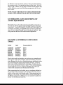
8.4 TYPICAT INTEREACE SITUATION
TABLE
Output
I nput
Gonnectshield at:
U nbalanoed
U nbalanmd
U nbalanoed
Baland
Balaned
Balanred
Differential
Differential
Differential
U nbalaned
Balaned
Differential
U nbalaned
Balaned
Differential
U nbalaned
Balaned
Differential
Output
Output
Output
I nput
Output
I nput
Output
Output
Output
Use the above table to interface your Axion to any external
"quipment such as multi-ttack machines, signal processing, and power
amps. Balanced (in the above illustration) means transformer balanced while differential means electronically balanced. Therc are
solne caseswhich net better results in practice. Connect one circuit at a time and check for hurn or noise. When connecting balanced microphones, use two conductor shielded audio cable and
connect both conductors and the shield at both ends.
When connecting line level cables, use two conductor shielded cable and follow the instructions in the interface table. The only exception to these rules is with patch co'rds. These grounds are tied
together in the console. \tr/e realize that the colaect interfacing of
all different equipment is difficult, but once goperly installed the
systern will be clean and noise free.
It is irnportant to understand the terrn balanced. Elalanced does not
rnean the input or output is professional, the single factor that norrnally deterrnines whether sornething is professional is the level of
the input or the output. +4 dBu is considered professional. -10
dBv i s c onsidered serni -professi onal . Elecause rnany serni-professi onal tape rnachines afe built to professional specifications, D&R
builds into the Axion console the ability to interface with both levels.
8.5.MASTER SECTION MODULE
CONNECTORS
All connectorson the Axion console are of the XLR 3 pin t14rc.
All audio connectors are wired as follows
Pin 1: ground
Pin2 : Hot (in phase)
Pin3 : Cold (out of phase)
The lamp connectors are differently wired and \ilill accept a 12
volt 5 watt lamp as a maximum.
Pin 1 :ground
Pin2: r l?volt
Pin3 : not connected
S/e recorffnand the use of t'Littlite" type 18XRA 18"
NOTE: The *Littlite" lurnp wiring has to be rnodified to rnatch the
*iring of the consoleslighting fernale XLR's. The reasonis that if
we did not modify this you could easily destnoya mictophone connected to these XLR sockets.
8.6 COhINECTING/ CONFTGURTNGOF
THE CIIAhINELMODULE
The channel backplate has the following 3 pin )(LR connectors:
IWc input
Line input
Insert send
Insert return
Direct outtrrut.
All connectors ate of the )(LR 3 pin type and have the international standard wiring whereby
pinl =ground,
piro=hot,
pin3:cold.
On the connector pcb's there are Molex 3pin locking connectors to
be used to wire rnultipin connectors to sorne or all of the irrloutputs. There ate also 4 pin headers to interface with optional trarrsforrners for the Line and Direct
output. The optional mic transforrner should be placed on the rnain pinted circuit board.
8.7JUMPER SETTINGS ON THE CIIAhINEL
The following changesin srgnal flow could be rnadeby jurnp"r settings on the printed circuit channel boards.
FU NCTION CONN. TYPE
DEFAULT SETTING
ALTERNATIVE SETTING
Dired output level (mnn-2)
Dired output (onn-3)
Meter seled (mnn-l)
Aux pre seled (onn-4)
PFL (onn-l0)
AFL (mnnl1)
+4 dBu
post cfrannelfader
linerutput
post M utdpct EQ
PFL-ON
AFL OFF(nojumpers)
-10dBV
Pre cfrannelfader
posnEQ output
pre M ute, pre EQ
PFL-OFF
AFL ON (bothjumpers)
The output level of the balanced output of the channel can be udj*ted by the VR1 trimmer, which mnges frcm infinity up to +6 dBu
if necessary.
Channel and gtoup inserts (sendsand returns) are used to patch
(rre-fade, pre EQ, post High passfiltet in the channel) into the
channel or group, any signal pocessing equipment such as compressorrs,limitets, equalisers etc.
The LINE INP[.)'I is used for plugging in the outputs of digital reverbs, digital delays, drum machines, samplets, keyboards, CD
players, cassettemachines and any machines with line level outputs.
The MIC INPUT is used for plugging in all types of microphones
or direct boxes. This is an active balanced input using the latest circuit technology available today. Each channel module has 48 volt
phantom powering indivually switchable.
DO NOT USE EXTERNAL PHANTOM POWERAND THE POWERING IN THE CONSOLE AT THE SAME TIME!
8.8JUMPER SETTINGS ON THE STERBO
CHAh[NEt
The following changesin signal flow could be rnadeby jurttper settings on the printed circuit stereochannel boards.
FUNCTION CONN TYPE
Aux 3 (onn-7)
Aux 4 (mnn-8)
DEFAULT SETTING
Left/summed mono
right/summedmono
ALTERNATIVE SETTING
fdlcnrysleft only
f ollouusright only
Ctrannel inserts (sendsand returns) are used to patch (pre-fade, pre
EQ, post High 1lrr filter in the stereo channel) into the stereo channel any signal processing equipment such as compressors,limitets,
equalisets etc.
8.9JUMPER SETTINGS ON THE GROUPI
MATRIXMOI}ULE
The following jurnper settings are available on the group rnatrix
rnodules.
FU NCTION CONN TYPE
DEFAULT SETTING
ALTERNATIVE SETTING
Mono to matrix (onn-8)
Right to matrix (onn-7')
Left to matrix (onn-g)
Group to matrix pr{post
group mute (onn-l)
Pre f ader to m at rix
Pre fader to matrix
Pre f adeer to mat rix
Posfifader to matrix
Pmt fader to matrix
Post fader to matrix
Pct grflp mute Pre grqrp mute
The following levels carrbr udjusted.
Matrix output levelfrorn infinity to +6dBu (+4dBu is the default
setting)
Group output level frorn infinity to +6dBu (+4 dBu is the default
setting)
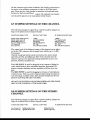
8.10 JUMPER SETTINGSAh[I} LEVELS ON
THE MASTER MOI}ULES
MODULEAUX rl7
The following levelscanb* udjustedfrorn infinity to +6dBu
(++dgu is the defaultsetting)
Aux 1,Aux 7,
MOIIULE AUX 218
zuNCTIONCONNTYPE DEFAULTSETTING
SETTING
Pharrtorn to Listen rnic
ALTERNATTVE
No phantorn power
The following levels can b* udjustedfrorn infinity to +6dBu
(++dgu is the default setting)
+48volt pharrtornpower
Aux 2, Aux8, Ivlain Left, I\{ain Right, PFL outtrrut,AFL left, AFL
right, Monitor left, Monitor right.
MODULB AUX 3le
FUNCTION CONNTYPE
SETTING
DEFAULT SETTING
ALTERNATTVE
Phantornto T.B. mic
No phantorn power
+48volt phantornpower
The following levels can b" udusted frorn infinity to +6dBu
(++deu is the default setting)
Aux 3, Aux9, Main Left, I\{ain Mono, Talk Back direct outtrrut,
On the frontpanel the side tone levels of the cotnrnunication systern
can be adjusted.
MODULE AUX 4lr0
FU NCTION CONN TYPE
DEFAULT SETTING
ALTERNATIVE
SETTING
Recout ldt, (onn-4)
Recout right, (mnn-s)
2Trad<A ldt in, (mnn-6)
2 TrackA right in, (onn-7\
2Track B left in, (mnn-8)
2Track B right in, (conn-g)
+4dBu
+4dBu
+4dBu
+4dBu
+4dBu
+4dBu
-10dBv
-1odBV
-10dBV
-1OdBV
-1odBV
-10dBV
The following levels can be adjustedfrorn infinity to +6dBu
(+4dgu is the default setting)
Aux 4, Aux 10, Record out left, Record out right,
MODULBAUX sftr
NO IUMPERS ON THIS MODULE
The following levels can b* udusted frorn infinity to +6dBu
(++deu is the default setting)
Aux 5, Aux 11,
Adjusfrnents can be rnade on the following ftitntners
VR5
VR6
VR7
VR4
distortion mcillator
distortionGdllator
output level ccillator only
output level pink noisegeneratoronly
MOrluLE
AUX 6112
NO JUMPERS ONTHIS MODULE
The following levels can be adjustedfrorn infinity to +6dBu
(++dgu is the default setting)
Aux 6oAux 12,
9.0 LINKING TWO AXION CONSOTES
It is possible to link two or rnore Axion consolesby "daisy chaining the rnale and fernale "'Link" corrrectots by "ordinairy" balanced rnic cables.
NOTE: It is advisable to cut the shield at the master consoleside!
As soon as two or rnore consolesare linked the solo systern is active on all consoles.Arry solo switch in any of two or rnore consoles, always activatethe rnonitoring in all consoles.So is the case
with the destructive solo in place systern.Any depressedsolo
switch will always put all other channelsinto rnute (if the consoles
are linked).
The usual way of linking two (or more) consolesis to connect
allGroups/h,latrixes/Auxesflrft/RightMono/PITI-/AFL-L/AFL-R
frorn one console to the next to createa masterfslaveconfiguration
whereby all rigtuls frorn the "slave" enter the "master" console.
NOTE:
It is very important to ground/connect the two consoles only at
their starground point and have the master slave conectors
only have their shields connected at the output of the slave console.
Power supplies can be grounded both if necessary. If ground
Ioops occur, remove the slave power supply grounding.
Every installation is different, so it is irnportant to be as consequent
as possible with reason,you rnust follow logic and only one systern of grounding for the best tesults.
Troubleshooting and servicing
10.0 Tboubleshooting
It is qssentialto study the signal flow chart carefully, only then can
you hope to isolate problerns. By tracing the signal frorn input to
output XLR's, it is possible to locate a ptoblern. If for any reason
you are unable to isolate a problem, contact the D&R Technical
Suppott Departrnent for advice. If the problern cannot be corrected
over the phone, D&R will despatch a replacenrent rnodule (ground
freight prepaid) the same day. Most problerns can be forHrd using
logical thinking and sirnply replacing socketed integrated circuits.
LO.LRemoving a Module
The Axion is a complex piece of equipment and some understa:ndingof its internal layout is necessarybefore removing a rnodule.
An input module has wiring to the master section and backplates
and the stargtound wire. Every 8 modules thete is a power
".tpplya
*iring. A11of these wires must be rcmoved before withdrawing
module from the console. Each module has computer grade connectors for easeof the disconnecl
Turn off the power supply. Remove the upper sfrip which covers
the module and the plexiglass.
Remove the two module retaining scl€ws. It is often easier to also
remove the modules positioned left and right of the module rmder
test. It is now possible to carefully lift the module until the module
*idng can be unplugged. Now temove all flat cables from the bottom of the module PCB. At this point extendet cables (if ordercd)
can be connected.
The master sections can be rernoved ftom the ftame in the sarne
way.
Becauseof the many flat cables on the bottom of the master section, it is wise to temove all retaining screws from all mastet sections, and remove the blankmodule on the left/nght side of the
master section. This willallow all the mastermodules to be moved slightly without unplugging all the flat cables. A qualified service technician will be able to service the modules in this way.
Dear Axion owner,
In this rnanual we have tried to grve you an ovenriew of all that the
Axion has to offer. If you have any questions, do not hesitate to
contact us o'r the D&R USA customer support department. With
the Axion series there is no limit to your creativity. We wish you
rnany years of enjoyable rnixing.
Best regards,
Duco de Rijk
PRESIDENTD&R, HOLLAND
This rnanual was written by Duco de Rijk (D&R Holland) and Paul
'We
hop" you will find it to be useful and
Westbrook (D&R USA).
easy to understand. As always, we are open to any suggestions
about this rnanual or any D&R product.
A person can feel a shock becausethe musclesin
a body respond to electrical current and because
the heart is a muscle it can affect, when the
curent is high enough. Current can also be fatal
This product is manufactured with the
when it causesthe chest musclesto contract and
highest standards and is double checked in
stop breathing. At what potential is current
our quality control department for reliability
in the
dangereous.
Well the first feeling of current is a tingle at
"HIGII VOLTAGE" section.
0.001 Amp of current. The current between0.1
Amp and 0.2 Amp is fatal.
CAUTION
Imagine that your home fuses of 20 Amp can
Never remove any panels,or open this
handle 200 times more current than is necessaq/
equipment.No user servicableparts inside.
Equipment power supply must be grounded at all to kill. How does resistanceaffect the shock a
person feels. A typical resistancebetween one
times.
product
hand to the other in udry" condition could well
in
user
Only use this
as described,
manualor brochure.
over 10Q000 Ohm.
Do not operatethis equipmentin high humidity
If you are plnying on stageyour body is
perspiring &emively and your body resistance
or exposeit to water or other liquids.
Check the AC power supply cableto assure
is lowered by more than 504/o.
securecontact.
This is a situation inwhich eutrent can easily
Have your equipment checkedyearly by a
Ilorr,. Current will flow when there is a difference
qualified dealerservicecenter.
in ground potential between equipment on stage
Hazardous electrical shock can be avoided by
and in the P.A. system.Pleasedo check ifthere
carefully following the above rules.
is any potential between the housing of the mikes
and the guitarsynth amps, which will be linked by
your body on stage. Imagine, a guitar in your
EXTRA CAUTION FOR LI\rE SOUND
Ground all equipmentusing the ground pin in the hand and your lips close to the mike! A ground
potential difference of above l0 volts is not
AC power supply cable.Never remove this pin.
Ground loops should be eliminatedonly by use
unusual, in improperly wired buildings it can
possiblybe as high as24Ovolts.
of isolation transfoffnersfor all inputs and
outputs. Replaceany blown fuse with the same
Allthough removing the ground wire sometimes
type and rating only after equipmenthas been
cures a systemhurL it will create a very
hazardeoussituation for the performing
disconnectedfrom AC power. If problem
persists,return equipmentto qualified selvice
musician.
Always earth all yoar equipment by the
technician
grounding pin in your mnins plug.
Hum loops should be only cured by propr
PLEASE READ THE FOLLOWING
wiring and isolation input/ouQut transformerc.
INTORMATION
Especially in sound equipment on stagethe
following information is essentialto know.
An electrical shock is causedby voltage and
Replace fuses always with the sametype and
rating after the equipment has been turned off
current, actually it is the current that sausesthe
shock.
and unplugged.
Ifthe fuse blows again you have an equipment
In practise the higher the voltage the higher the
failure, do not use it again and return it to your
current will be and the higher the shock.
dealer ficr repair.
But there is anotherthing to considerand it is
resistance.When the resistancein Ohms is high
And last but not least be carefull not to touch a
between two poles, the current will be low and
personbeing shockedas you, yourselfcould also
vica versa.
be shocked.
All three of these;voltage, current. and
resistanceare important in determiningthe effect Once removed from the shock, have someone
send for medical help inmediately
of an electrical shock.
Aways keq the a.bovementionedinfarmdion
However, the severity of u shock prtmurily
in mindwhen using electrically powered
determined by the &moant of current Ilnring
PROI}UCT SAFETY
throughupercon.
equipntent.
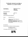
Conformity statementaccordingto
ISOIIEC Nr. 22 and EN 45014
Name Manufacturer
Addres manufacturer
D&R Electronica Weesp b.v.
Rijnkade 158,
1382 GS Weesp,
The Netherlands
declaresthat this product
Name product
Modelnumber
Produktoptions
AXION series
n.a.
AII
passedthe following product specifications:
Security
EN 60950:1988+Al , A2
EMC:
CISPR-ZZ:1985/ EN 55022:1988classB (*)
EN 50082-1:1992
- 3kV CD,8kV AD
IEC 801-221991
/ prEN 55024-2i1992
- 3 V/m
IEC 801-3:1984
/ prEN 55024-3:1991
- 0.5kV signalcables,
IEC 801-421988
/ prEN 55024-421992
I kV powercables.
Extra information:
The product passedthe specificationsof the following regulations;
Low voltageT3123I EF,G
EMC-regulations89 / 336 / EEG.
(*) The product is testedin a normal usersenvironment.
Dffi