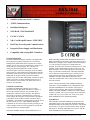
1
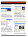
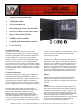
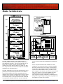
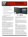
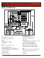
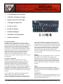
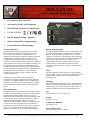
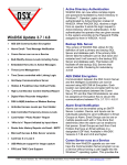
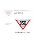
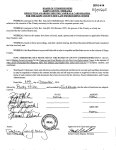
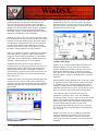
WinDSX ® Microsoft Access™ and SQL Server™ Editions WinDSX is a powerful access control and system monitoring application that harnesses the power of the Windows XP, Vista, and 7 Professional™ operating systems. WinDSX combines point monitoring and access control with Photo ID Badging, Time and Attendance, Alarm Graphics, DVR/NVR Integration, Elevator Control, Alarm Email/Text Message Notification, Threat Level Management, HazMat / Emergency Lockdown, and FIPS/TWIC card compatibility. Graphic alarm maps can be configured to provide detailed information about any I/O point in the system. The graphic map displays the true real time status of each I/O point and allows the operator to perform manual overrides of the inputs and outputs directly from the map. WinDSX can support your access control needs from a single PC or multi-user Local Area Network to an enterprise solution with SQL Server as the database engine. The system utilizes TCP/IP network communications to provide user interaction and real time monitoring to the workstation PC’s located anywhere on the LAN or WAN. Password protection allows for operator specific capabilities at each workstation. There are two Editions of Software. WinDSX comes standard with a Microsoft Access database engine. WinDSX SQL is designed to work with Microsoft SQL Server as the database engine. Both editions of WinDSX have similar features and capabilities. Microsoft SQL Server is user supplied. WinDSX implements Point and Click operation with hierarchical tree views and pop up menus for ease of use. I/O monitoring and control is achieved through animated icons that depict the real time status of each input or output. I/O points can also be assigned to an Override Group to allow for multiple inputs and outputs to be monitored and controlled from a single icon. Scheduled Overrides can be assigned to individual Inputs and Outputs as well as Override Groups. These schedules allow operators to quickly assign time and date sensitive instructions determining the open/secure status of outputs and the armed state of inputs. Graphic Alarm Maps Cameras can be controlled with standard pan/tilt and zoom functions when the system is connected to a matrix type switcher. WinDSX has the ability to integrate with over 20 different DVR and NVR systems. This integration allows stored and live video from the DVR to be accessed within the WinDSX software. All video is transmitted across a network connection. WinDSX flexible linking capabilities allow for any card, input or output in a location to link (interlock) with any other input or output in that location. Complicated applications such as mantraps are simply a matter of programming and require no additional equipment. This allows for custom solutions such as floor select elevator control and automatic handicap doors. Custom History reports can be defined choosing any combination of locations, doors, events, and cardholders providing as general or specific a report as needed. The reports can be previewed before printing and can be sent to a local printer or any printer on the LAN. Report configurations can be saved and run at any time. History reports can be preconfigured and automatically run up to twice a day each day of the week and even Emailed from the workstation they were created on. Workstation Desktop With the new Global Access Level Manager an unlimited number of temporary and permanent access levels can be assigned to card holders. These Access Levels now span across grouped locations. Temporary Access Levels are date controlled. DSX Access Systems, Inc. 10731 Rockwall Road Dallas, Texas 75238 / 888-419-8353 / 214-553-6140 / www.dsxinc.com 11/2012 The Card Holder Name Search window is available by clicking on the Binocular Icon button in the top left corner of the Workstation Program. It can be used to Search for a Card Holder by Name, or a more in depth search can be made. Full or partial spelling can be used in the search. The results of the Name Search are displayed here along with their current In/Out Status, location of last card use, and other information. The following picture is the Card Holder data entry screen. This is where the card holder data is entered, images are imported or captured, and badge printing takes place. Card Holder Data Entry Screen Card Holder Name Search By clicking on the Search button without entering a name, a list of all cardholders is returned which can be scrolled through viewing UDFs and status of each card holder. If the In/Out button is selected the In/Out Status screen is displayed. The blue status bar at the top displays the door, date and time of the highlighted cardholder’s last card use. Green indicates the card holder is “In” and Red indicates the cardholder is “Out”. All Cardholders that are “In” (green) are alphabetically sorted to the top. All Cardholders that are “Out” are alphabetically sorted to the bottom. This In/Out display is updated once a minute. Left click one time on any cardholders name to refresh that person’s information. The digital images are permanently stored on the hard disk with other cardholder data. These images can be sized, cropped, edited, and placed anywhere on any badge background. Any number of images can be stored with each cardholder, including front and side views, signatures, finger prints, etc. Badge templates are created using “What You See Is What You Get” drag and drop tools with new features such as transparent backgrounds, image ghosting, text centering, text shrink to fit, right alignment, bring to front - send to back layering, and rotation to any degree. The ability to create unlimited badge templates allows for all departments and user groups to have unique badges. Single sided or two sided color and monochrome badges can be printed one at a time or in a batch mode. In / Out Status Screen WinDSX is the one stop solution for Video Imaging/Photo ID Badging and Access Control applications. The WinDSX system can produce photo ID badges for employees and visitors. The system allows the user to create badge backgrounds (templates) on which digital images and card holder data is imposed when the card is printed. Video Imaging is a standard feature of the WinDSX system that is provided at no extra charge. Images can be captured with a digital camera and imported into the WinDSX system without any additional hardware or expense. If live video display and capture is desired a DSX Badging Camera can now be used without the need of a DSX Features Key. The DSX Camera allows the operator to capture still shots from a high resolution live feed USB connected Camera. Badge Print Preview/Edit A print preview feature displays the assembled badge prior to printing. All images on the print preview can be zoomed in and out and adjusted from left to right for last minute changes. DSX Access Systems, Inc. 10731 Rockwall Road Dallas, Texas 75238 / 888-419-8353 / 214-553-6140 / www.dsxinc.com 11/2012 WinDSX Software Specifications and Features Microsoft Access or SQL Server Editions 32,000 Locations 128 Doors / Readers per location 50,000 Access Codes per location 32,000 Time Zones with 3 Holiday overrides each 32,000 Access Levels 32,000 Inputs 32,000 Outputs 32,000 Companies 32,000 Holidays 99 User Defined Fields 32,000 System Operators 32,000 Password Profiles 999 Operator Comments 32,000 Graphic Alarm Maps 32,000 Custom Action Messages Import Graphic Alarm Maps of 21 file types 240 + Card Reader, Keypad format compatibility FIPS/TWIC Card Compatibility up to 17 digits 32,000 ASCII Output Messages Time and Attendance Guard Tour CCTV & Pager System Interface - ASCII / Relay Output DVR/NVR Integration Auto Incremental Downloads (changes only) Floor Select Elevator Control and Reporting High Level Elevator Control Interface/Report After Hours HVAC Zone Control Global Input/Output Linking Global Code to Input/Output Linking 4 Zone Global Anti-Passback w/Hard, Soft, and Timed Integral Database Backup and Restoration System –Access only Auto-Backup procedure/ Backup to any storage media Integral Custom Report Generator w/Report Pre-viewing Schedule Automatic History Reports / Email using SMTP “Who Is In” One Button Report including Input Activated Card Holder “Photo Roster” Report Code Tracing - Reader and User selectable Regional Time Zones for Workstations and Remote Sites Fail Safe or Fail Secure Relay Action Icons for Input Normal/Abnormal states Icons for Output On/Off states Direct, Dial-up Modem, and TCP/IP Panel Communications DSX-LAN(M) Interface w/ Modem Backup Communications Schedule or defer downloads Limit Number of Card Uses 1-10,000 / Card Disable Reader TCP/IP Network Protocol support Integral Photo ID Badging and Photo Verification w/Image Auto/Manual Image Recall Workstation Event Filtering Operator Audit Trail Alarm Echo - Offsite Alarm Monitoring / Remote Control Visitor Management Multiple De-activate Dates for Cards Auto Incrementing Badge Number Threat Level Management Continued…. Global Access Level Manager Unlimited Access Levels Per Card Holder Date Controlled Temporary Access Levels Card Use It or Lose It automatic deactivation by Company Precision Start Times and Dates for Card Activation Precision Stop Times and Dates for Card De-activation Card Holder Biometric Enrollment Export Embedded Hot Links in Action Messages Multiple Dates on Scheduled Overrides Time Zones controlled with Linking Logic Hot-Swap Backup Communications Server – SQL only Hidden & Predefined User Defined Fields Alarm Email Notification / Text Messaging Comm Server (CS.exe) runs as a Service Bulk modification to Card Holder Access Levels AES Encryption from Comm Server to all Controllers AES Encryption from Comm Server to all Workstations Startup Map (always displayed) + Custom Map Sizes Device Locator- shows which Access Levels contain a Device WinDSX Badge System Features Digital Camera Pan and Tilt Batch Card Printing Image / Signature Importing Multiple Video Input Compatibilities Image Capture Transparent Backgrounds Multiple Images for each Person Image Cropping and Editing Auto Image Editing Rotate Text and BarCodes Encode Magstripe Track 1, 2, 3 with equipped card printer Prints to any Windows Compatible Card Printer Manual Image Recall by Clicking on Card Read Event Auto Image Recall by Device, up to two time zones each Generates 3 of 9 and interleave 2 of 5 Barcodes Single Sided or Double Sided Badges Color and/or Black and White Badges Text Centering Shrink to Fit text and data fields Right Alignment Font and Text Color selection for each printed field Text Underlining WYSIWYG + XY Coordinates File Import using Digital Camera Import 18 different Graphic Image file formats Resize Image and Maintain Aspect Ratio Shapes with custom colors available Name field concatenation Image Ghosting Bring to Front / Send to Back Layering Auto Badge Template selection Auto-Incrementing Badge Number Card Holder Photo Roster Report CR-80 to CR-100 Card Sizes USB WebCam Support – No Features Key Required DSX Access Systems, Inc. 10731 Rockwall Road Dallas, Texas 75238 / 888-419-8353 / 214-553-6140 / www.dsxinc.com 11/2012 Video Imaging Components DSX CamKit = USB Badging WebCam, Remote Control, USB Cables, and power adapter. All components have a 1-year warranty. CPUs Minimums Pentium 2.8 GHz Dual Core (or better) Pentium 2.3 GHz Dual Core (or better) Pentium 3.3GHz Dual Core (or better) Camera Specifications: Motorized pan, tilt and zoom USB video class (UVC) supported applications Full HD 1080p Camera and remote control 10-foot range remote control Pan, tilt and zoom Carl Zeiss Optics with 9 point auto focus 78-degree field of view 180-degree pan, 55-degree tilt USB 2.0 compliant 8-foot USB cable 8-foot universal power adapter 9-inch extender stem for elevation Windows 7, XP, and Vista Printers: WinDSX prints to any Windows™ compatible direct card printer such as Zebra and Fargo. Application Host PC for single PC, single location, or LAN workstation for single location system. 2G RAM LAN Comm Server or File Server for single location, or workstation for multi-location system. 2G RAM LAN Comm Server and/or combination File Server for multilocation. 4G RAM - minimum Memory Minimums 2G 4G+ Application Basic System, Single PC Multi-Location Comm Server and Badging Drive Minimums CD/DVD 16x or better 1G Hard Drive Space minimum Application Software Installation Basic System requires 50M LAN Communications Adapter 10/100Mbit or better Requires TCP/IP Protocol Comm Server LAN Modules Comm Server to Controller Comm Server to Workstation 100M is recommended MS LoopBack Adapter for no LAN Static IP Address Static IP Address UDP - ports 4000 to 5000 TCP - ports 22223 / 22224 Sound Windows™ compatible sound card. Application WAV files for input alarms. Backup Gear Windows™ compatible Backup gear. Application WinDSX can send backups to logical drive. WinDSX SQL uses SQL Server for backups. Modem DSX External dial-up DSX only supports DSX modems Serial Ports DSX-USB Communications adapter USB to RS-232 / RS-485. Direct and Dialup communications require a serial port. Client Operating Systems Windows™ 8 Professional Windows™ 8 Pro 64 bit Windows™ 7 Professional Windows™ 7 Pro 64 bit Windows™ Vista Business Svc Pack 1 Windows™ XP Professional Svc Pack 2 The Comm Server Program can run on a Client Operating System. Server Operating Systems Server 2003 Server 2008 Server 2008 R2 Server Operating Systems require the use of Active Directory. SQL Server SQL 2005 Svc Pack 3 SQL 2008 SQL 2008 R2 SQL 2012 DSX Version 3.7 / 4.7 and higher 3.7 / 4.7 and higher 3.7 / 4.7 and higher 3.7 / 4.7 and higher Peripherals require 64 bit drivers. 3.7 / 4.7 and higher 3.5 / 4.5 and higher 3.5 / 4.5 and higher 3.7 / 4.7 and higher 3.7 / 4.7 and higher WinDSX SQL requires Microsoft SQL Server. WinDSX uses Microsoft Access. 3.7 / 4.7 and higher 3.7 / 4.7 and higher Additional configuration required DSX Access Systems, Inc. 10731 Rockwall Road Dallas, Texas 75238 / 888-419-8353 / 214-553-6140 / www.dsxinc.com 11/2012 DSX-1022 Intelligent Two Door Controller 8 Supervised Programmable Inputs 4 Fused Relay Outputs TCP/IP Communications 240+Card/Keypad Formats also FIPS/TWIC Flexible I/O Linking - Local & Panel to Panel Installs in 1021 and 1022 Enclosure 512K RAM / 512K Flash ROM Compatible with all existing DSX Controllers UL 294 / UL 1076 General Information The DSX-1022 is an independent processing, two door intelligent controller designed to be a cost effective building block of the DSX hardware platform that allows expansion in a scalable manner. Up to 2 doors can be controlled from 1 enclosure allowing it to be strategically deployed where a few number of readers are required such as parking garages, gates and other remote situations. This newly designed controller has several new features such as fuses in line with the common terminals on all four relay outputs. Battery Test and Load Shed are also new features incorporated into the panel to protect the panel and its backup battery. The DSX-1022 carries a Limited 2 Year Warranty. Time Zone control with Holiday overrides for Inputs, Outputs, and Cards even when communication to the PC or other Controllers is not available. Reader Technologies The DSX-1022 is compatible with Wiegand, Barium Ferrite, Proximity, Bar Code, Magnetic Stripe, Biometrics and Smart Card readers. Any combination of reader technologies may be used in the same system. A keypad may be added to most readers to create a Card and/or PIN controlled entry point. The DSX-1022 is compatible with over 240 different card readers / keypads and card formats which make it the perfect panel for retrofits. DSX Controllers support FIPS and TWIC Cards. Controller Architecture The DSX-1022 Intelligent Controller (panel) is designed as a unitized (processor and I/O board combined) controller with small space requirements that accommodates two discreet reader/keypad controlled doors. The DSX-1022 can be used in conjunction with all other DSX Controllers as a Master or Slave in the Controller Network. The first Controller of each location is designated as the Master. The Master is responsible for communications to the PC and to the Slave Controllers. The unitized DSX-1022 controller contains an AM186 processor, RAM, ROM, power supply, and removable field wiring terminals. Each DSX-1022 operates as a fully distributed processing control panel that retains all data necessary for system operation in its own RAM. Each DSX1022 checks its database to make decisions about access control, alarm monitoring, and time zone changes. The DSX1022 has an integral real-time clock and calendar which allows Memory The DSX-1022 has a standard configuration of 512K of Flash ROM and 512K of RAM. The RAM memory allocation is dynamic between database and event storage and set for optimum use by the Host PC according to data entered for that location. Inputs The DSX-1022 has 8 EOL supervised Inputs capable of two, three, and four state point monitoring with status LEDs. The armed status of each Input can be controlled by up to 4 Time Zones, I/O & Card Linking, and manually from the PC. Two Inputs (input 7s) are designated as the Door Position Inputs for the reader controlled doors. Two Inputs (input 8s) are designated as the Exit Request Inputs for the reader controlled doors. The remaining four Inputs are then left for point monitoring of any contact closure output device. DSX Access Systems, Inc. 10731 Rockwall Road Dallas, Texas 75238 / 888-419-8353 / 214-553-6140 / www.dsxinc.com 11/2012 Outputs The DSX-1022 has six Outputs. Two Outputs (output 1s) are the Form- C, fused at 1 Amp, relay outputs to control the locks for the reader controlled doors. Two Outputs (output 2s) are also Form-C, fused at 1Amp, relay outputs that are programmed and used in the same ways as all other outputs. All Relay Outputs have 1A fuses in series with the Common terminal. Two Pre-Warn Outputs of the DSX-1022 are used to indicate the controlled doors are being held open and about to go into alarm. If the door is locked, armed, and opened, the output pulses low starting at 1/3 of the door open too long time and changes to a steady low anytime the door is in alarm. These open collector outputs reset automatically when the door is closed. Communications The DSX-1022 Intelligent Controller can communicate with the Comm Server (Host PC) via TCP/IP, Direct serial port, and dial-up modem. TCP/IP LAN Communications can be utilized from the WinDSX Comm Server PC to a Master Controller. The WinDSX Software without the use of any additional Hardware or Software will redirect what would typically be serial port communications to a TCP/IP address. A DSX-LAN(M) serial device at the Master Controller receives the communications over the LAN converts it to RS-232/RS-485 for the Master Controller. The end result is real time communications similar to that of a direct serial port connection. Direct Connect Communications to the PC from the Master 1022 Controller is performed with the use of the MCI module which connects to the comm port of the PC and converts the RS-232 signal from the PC to RS-485. The RS485 communications from the MCI to the Master utilizes two twisted pair cable for the data and one pair for power. The RS485 output of the MCI will support up to 4000 feet of cable distance. The controller communicates with the PC at a default baud rate of 9600. As long as the communications signal arrives at the Master as RS-485 and RS-232 at the PC in an asynchronous, full duplex mode, operating at 9600 baud, the method of communication in between can be just about any mode of transport such as Direct Wire, T1, Lease Line, or Fiber Optics. Dial-Up Modem Communications from the DSX-1022 Master Controller to the PC utilizes a DSX-Modem and DSXMCI module at the Controller and a DSX-Modem at the PC. At the DSX-1022 Master, the RS-485 Host Communications Port connects to a DSX-MCI module which converts the RS485 of the Controller to RS-232 for the Modem (the MCI is not required for the new DSX-Modem). The DSX-MCI and Modem derive power from the 12VDC output of the DSX1022 panel. The Controller will auto-dial to the PC all alarm and supervisory conditions. The controller can also be programmed to dial the PC when its event buffer is 80% full. Panel to Panel Communications is a true point to point, regenerative, RS-485, 4-wire, communications method. This allows the panel to panel network communications to be regenerated at each controller providing up to 4000 feet of distance between controllers over two twisted pair cable. Panel to Panel communications can be configured in a series loop, star configuration, or both. Star configurations require a DSX1035 Quadraplexor. DSX-1022 Specifications Size Cabinet 15.5” W x 13.5” H x 6.0”D DSX-1022 10.5” W x 7.5” H x 1.5” D Weight Cabinet 11.00 lb. DSX-1022 1.60 lb. Package Total 12.60 lb. Finish Black Powder Coat on Enclosure and Black Enamel on Shield Temperature/Humidity Operating 32 to 131 F / 0 to 95% relative - Storage -35 to 150 F Supply Voltage Panel Voltage 16.5 VAC 40VA – For UL 1076 use two transformers. Power Requirements 33 Watts (112.6 BTU) Panel Current Draw 540 ma UL Listed or CSA Certified Class II Transformer Required. Output Voltage Panel Output 12VDC 1A - Fused Panel Output 5VDC 1/2A - Fused Inputs EOL Supervised 8 UL Installations require a Tamper Switch to be connected to an Input programmed with a 24hr Time Zone. Outputs Form C Relays (1-2) 4 fused at 1A Relay Ratings 5 AMP 30 VDC LED Outputs 6 - 3 per reader - open collector 100ma Pre-Alarm Outputs 2 - 1 per door - open collector 100ma Access Controlled Entry Points Card Reader or Keypad 2 Any combination of card readers, keypads, or card and keypad controlled entry points may be used. Over 240 types available including FIPS/TWIC cards up to 17 digits. Battery Charging Output Trickle Charge 13.5 VDC 500ma Fused / Standby Time 3.3 hours under maximum load. For UL Installations, battery must be Powersonic PS-1270, Interstate PC-1270, or a SBS S-1272. For UL1076 use two batteries. Communication Ports RS-485 In (2) 1 for Master to PC, 1 From Slave RS-485 Out 1 To Subsequent Slaves DSX-1022 Master Controller requires a MCI Module for direct serial port communications. Processor AM186 20Mhz RAM Memory Standard 512K * The transaction buffer automatically adjusts to utilize any RAM not allocated for system parameters. Warranty Limited 2 Years DSX Access Systems, Inc. 10731 Rockwall Road Dallas, Texas 75238 / 888-419-8353 / 214-553-6140 / www.dsxinc.com 11/2012 DSX-1048 Intelligent Controllers Scalable Architecture from 2 - 8 doors TCP/IP Communications Individual Intelligence 512K RAM / 512K Flash ROM UL 294 / UL 1076 240+ Card/Keypad Formats - FIPS/TWIC Real Time Processing and Communications Integrated Power Supply and Distribution Compatible with existing DSX Controllers General Information The DSX-1048PKG Intelligent Controller is an independent processing 8 door package designed to be a cost effective building block platform that allows expansion in a scalable manner. Up to 8 doors can be controlled from 1 enclosure for an efficient space saving package. The controllers are strategically placed throughout the customer location connected together with a two twisted pair cable. Each DSX1048 operates as a fully intelligent and independent controller that retains all data necessary for system operation in its own RAM. With its integral real-time Clock and Calendar it performs Time Zone control with Holiday overrides for inputs, outputs, and cards even when communication to the PC or other controllers is not available. The DSX-1048 carries a Limited 2 Year Warranty. Controller Architecture The DSX-1048 Intelligent Controller may be used in conjunction with all other DSX Controllers as a Master or Slave in the controller network. Any controller may be designated as a Master or Slave controller. The Master or Slave mode of operation is determined by the panels dip switch settings. The first panel of each location is designated as the Master while all others would be considered Slaves. The Master is responsible for communications to the PC and to the Slave panels. Up to 16 - DSX-1048PKG Intelligent Controllers can be used in a single Location providing for 128 readers. Multiple Locations can be grouped for systems that require more than 128 readers/keypads. Each DSX-1048PKG includes a DSX-1040E Enclosure, a DSX-1040CDM Communication Distribution Module and 4 DSX-1042 Intelligent Controllers. Each DSX-1048 provides 8 Reader Ports, 32 Inputs, and 16 Outputs. Each DSX-1042 has a 12 volt fused power output for its Card Readers and Keypads. The DSX-1042 contains an AM186 processor, 512K of RAM, 512K of Flash ROM, and a Real Time Clock. The DSX-1048 allows all door and field wiring connections to be made via removable terminal blocks. The DSX-1040CDM receives RS-485 communications from a possible previous panel and regenerates the 4 wire-RS485 to the next DSX1048PKG. The DSX-1040CDM also distributes Slave Controller communication to those Slave panels located within the same enclosure. Used in conjunction with the DSX-1048PKG Intelligent Controller is a DSX-1040PDP or Power Distribution Panel. The DSX-1040PDP houses the controller and lock power supplies, backup batteries, and fused power distribution module. The DSX-1040PDP is comprised of a DSX-1040PE enclosure, an SWS-150 15V power supply for the controllers, a SWS-150[15] or [27] for either 12V or 24V locks, and a DSX-1040PDM or Power Distribution Module. System Power Each Controller in the DSX-1048PKG is powered from an individually fused 12 volt output from the DSX-1040CDM distribution module located in the same enclosure. The module also provides 5 volt power for those Readers and or Keypads that require it. The DSX-1040CDM receives power from the DSX-1040PDP Power Distribution Panel. DSX Access Systems, Inc. 10731 Rockwall Road Dallas, Texas 75238 / 888-419-8353 / 214-553-6140 / www.dsxinc.com 11/2012 The DSX-1040PDP houses the controller and lock power supplies, backup batteries, and fused power distribution module. The DSX-1040PDP is comprised of a DSX-1040PE Enclosure, an SWS-150 15V power supply for the controllers, an SWS-150-[15] or [27] for either 12Vor 24V locks, and a DSX-1040PDM Power Distribution Module. The DSX1040PDM performs several critical functions. First, it takes the 15V power from the SWS-150 and provides two 3A Class II, Power Limited, fused outputs to power the DSX-1040CDM which distributes the power to the DSX-1042 Controllers in the DSX-1048PKG. It provides a 12VBattery Charging Circuit to charge backup batteries for the controllers. It also provides a charging circuit for the optional batteries used to backup the 12 or 24 volt lock power from the SWS-150 lock power supply. The Power Distribution Module has 3 N.C. Relay Outputs, two to signal Loss of AC (one for lock power and one for controller power) and one to signal Low Battery. These Outputs can be connected to spare Inputs in the DSX1048PKG. The module also has a Battery Test Input. This Input when activated shuts off the charging circuit and load tests the battery for 1 minute. This Input can be connected to a spare Output in the DSX-1048PKG and programmed by time zone to occur when desired. The DSX-1040PDM routes Lock Power through individual fuses for each of the 8 Class II, Power Limited, outputs. The module also has an input for a Fire Override relay contact to break Lock Power and has a Fire Override Output to connect to the next 1040PDM. All Outputs are Class II, Power Limited. When the Controller is in service the amount of RAM and the version of ROM can be viewed from the DSX communications software. Reader Technologies The DSX-1048PKG Intelligent Controller can communicate with the WinDSX Communications Server via TCP/IP LAN communications, Direct Serial Port connection, and Dial-Up Phone Modem. TCP/IP LAN Communications can be performed from the WinDSX Comm Server PC to a Master Controller. The WinDSX Software without the use of any additional Hardware or Software will redirect what would typically be serial port communications to a TCP/IP address. A DSX-LAN(M) serial device at the Master Controller receives the communications over the LAN from the WinDSX PC and converts it to RS-232/RS-485 for the Master Controller. The end result is real time communications similar to that of a direct serial port connection. The DSX-1048 is compatible with Wiegand, Barium Ferrite, Proximity, Bar Code, Magnetic Stripe, Biometric, and Smart Card readers. Any combination of reader technologies may be used in the same system. A keypad may be added to most readers to create a card and/or PIN controlled entry point. The DSX-1048 is compatible with over 240 different card readers / keypads and card formats which make it the perfect panel for retrofits. Conversion modules exist for some types of other manufacturers proprietary card readers. The panel is compatible with two wire wiegand and clock and data outputs without the use of any modules. Each reader port has 3 LED open collector outputs for Door Secure, Door Open, and Access Denied/Keypad PIN Entry. This will accommodate almost any reader and LED configuration. It is possible to connect the sounder control line of most card readers directly to the Pre-Warn output for door held open annunciation. Memory Each Controller has a standard configuration of 512K of Flash ROM and 512K of RAM. The RAM memory allocation is dynamic between database and event storage and set for optimum use by the Host PC according to data entered for that location. Flash ROM allows for the Controllers’ operating system to be upgraded without the changing of chips (EPROMS). Having 512K of RAM eliminates the necessity of increasing the memory in controllers as the system grows. Inputs The DSX-1048PKG has 32 EOL supervised Inputs capable of two, three, and four state point monitoring with trouble reports. The armed status of each Input can be controlled by up to 4 Time Zones, I/O & Card Linking, and Manually from the PC. Eight Inputs are designated as Door Position and eight Inputs are designated as Exit Request Inputs for the reader controlled doors. The remaining sixteen Inputs are then left for additional monitoring points. Outputs The DSX-1048PKG has 16 Programmable Outputs. Eight Outputs are Form-C, 5 Amp rated relays used to control the locks for the reader controlled doors. Eight Outputs are the open collector type, both have an LED for status and are fully programmable. In addition to the 16 programmable Outputs there are 8 Pre-Warn Outputs, (1 for each door) and are used to indicate the reader controlled doors are being held open and are about to go into alarm. Once the door is opened the Output begins pulsing low starting at 1/3 of the door open too long time and changes to a steady low anytime the door is in alarm. These open collector (switched negative) outputs reset automatically when the door is closed. Communications Direct Connect Communications from the PC to the Master Controller is performed with a connection from the Host Port of the Master to a USB port of the PC. RS-232 is used for short distance connections. RS-485 communications is used when the direct serial port connection is from 50 to 4000 feet from Controller to PC. In order to communicate with the Master Controller with RS-485 communications requires two MCI modules. One DSX-USB module is placed at the PC to convert the USB to RS-485 and a DSX-MCI (second module) is placed at the Master Controller to convert the RS485 back to RS-232. The Controller communicates with the PC at a default baud rate of 9600. DSX Access Systems, Inc. 10731 Rockwall Road Dallas, Texas 75238 / 888-419-8353 / 214-553-6140 / www.dsxinc.com 11/2012 Dial-Up Modem Communications from the DSX-1042 Master Controller to the PC utilizes a DSX modem at the Controller and one at the PC. At the DSX-1042 Master, the RS-232 Host Communications Port connects to the Modem. The Modem derives its power from the DSX-1042 panel. The Controller auto-dials to the PC all Alarm and Supervisory conditions. The Controller can also be programmed to dial the PC when its event storage buffer is 80% full. Controller Communications is handled at each DSX-1048 by a DSX-1040CDM (communications distribution module) using true point to point, regenerative, RS-485, 4-wire communications. This module has 2 RS-485 ports for in and out 4 wire communications to other Controllers. The Controller network communications is regenerated at each DSX-1040CDM allowing up to 4000 feet of distance between Controllers over two twisted pair cable. The DSX-1040CDM has 2 RS-232 Communication Ports. One is used to connect to the Master Controller and is only used in the DSX-1048PKG Enclosure where the Master Controller resides. The other RS232 port connects to the RS-232 port of each Slave Controller in that same enclosure. DSX-1048PKG Controllers are connected in a series loop configuration unless a DSX-1035 Quadraplexor is used for Star wiring. DataBase Downloads The Controllers utilize a synchronized database that is maintained with the incremental and automatic or scheduled downloading of changes only. This intelligent, independent processing increases the speed of the panel’s actions and reactions, providing more stability and security to the overall system. The Controllers are downloaded with all parameters the first time they are brought on-line. Once the initial full download occurs all database changes such as the adding and deleting of card holders are sent to the Controllers by way of incremental downloads. The Controllers’ transaction buffer automatically adjusts its size to utilize any RAM not allocated for data. Diagnostic, Supervisory and Status LEDs The DSX-1048 has 88 diagnostic LEDs to indicate panel status. Thirty two are for Input Status, and sixteen are for Output Status. The rest are for Communications, Fuse Status, and Processor Status. DSX-1048 Specifications Size DSX-1040E Cabinet 15.5" W x 22.5" H x 6" D DSX-1040CDM 11" W x 4.5" H x 1.5" D DSX-1042 11" W x 4.5" H x 1.5" D Weight DSX-1040E Cabinet 19.2 lb. DSX-1040CDM 1.0 lb. DSX-1042 1.2 lb. DSX-1048 - Total 25.0 lb. Finish Black Powder Coat with White Silkscreen on Enclosure and Black Enamel on DSX-1042. Enclosure / Conduit Knockouts Concentric knockouts in Top, Bottom, and Sides. Knockouts accommodate 1/2, 3/4, 1, 1 3/4 inch conduit. Nema Type 1 equivalent enclosure with lift-off hinged door, lock/key, and tamper switch. Temperature Operating 32 to 131 F Storage -35 to 150 F Humidity Operating 0 to 95%, relative Power Requirements DSX-1042 13.5 VDC @ 300ma from 1040CDM DSX-1040CDM 13.5 VDC @ 150ma from 1040PDP Total Maximum Current 13.5 VDC @ 6.0A Output Voltage Panel outputs provide a regulated, fused, DC voltage. DSX-1042 9-13.5VDC - 12VDC nominal - 1A Fused DSX-1040CDM 9-13.5VDC - 12VDC nominal - 1.5A Fused DSX-1040CDM 5VDC - .5A Fused All Outputs are Class II, Power Limited Inputs EOL Supervised 32 16 Inputs are used for standard point monitoring. 16 Inputs are used for door position and exit request monitoring. All Inputs support two, three, and four state monitoring with five programmable circuit types. Outputs Form C Relays 8 Relay Output Ratings 5 AMP - 30VDC Open Collector Outputs 8 - negative 100ma LED Outputs 24 - 3 per reader port - negative 100ma Pre-Alarm Outputs 8 - 1 per door - negative 100ma Access Controlled Entry Points Card Reader or Keypad 8 Card and Reader Formats 240+ including FIPS/TWIC Any combination of card readers, keypads, or card and keypad controlled entry points may be used. Communication Ports DSX-1042 RS-232 In 1 Master to PC RS-232 Out 1 Panel to DSX-1040CDM 1040CDM RS-232 In 1 Master to DSX-1040CDM RS-232 Out 1 Slave Communications RS-485 In 1 From previous DSX-1048 Package RS-485 Out 1 To subsequent DSX-1048 Packages Processor AM186 20Mhz RAM/ROM Memory Flash ROM 512K Standard RAM 512K Warranty - Limited 2 Years DSX Access Systems, Inc. 10731 Rockwall Road Dallas, Texas 75238 / 888-419-8353 / 214-553-6140 / www.dsxinc.com 11/2012 Basic Architecture The DSX-1048PKG includes a DSX-1040E Enclosure, a DSX-1040CDM Communication Distribution Module and 4 – 1042 Intelligent Controllers. This provides 8 Reader Ports, 32 Inputs, and 16 Outputs. The DSX-1048 Package comes complete with 32-1K ohm EOL Resistors, Lock & Key, Wire Ties, Tamper Switch, an External Power Indicator and a DSX1040PDP Power Distribution Panel. The DSX-1040CDM receives RS-485 communications from a possible previous panel and regenerates the 4 wire-RS485 to the next DSX-1048PKG. The DSX-1040CDM module also distributes Slave Controller communication to the Slave panels within the same enclosure. Each DSX-1042 is powered from an individually fused 12 volt output from the DSX-1040CDM Communications Distribution Module. The DSX-1040CDM receives power from the DSX-1040PDP Power Distribution Panel. Used in conjunction with the DSX-1048PKG is a DSX1040PDP or Power Distribution Panel. The DSX-1040PDP houses the panel and lock power supplies, backup batteries, and fused power distribution module. The DSX-1040PDP is comprised of a DSX-1040PE Enclosure, an SWS-150 15V power supply for the Controllers, an SWS-150-[15] or [27] for either 12Vor 24Vlocks, and a DSX-1040PDM. The DSX1040PDM performs several critical functions such as supervising Power Supplies and Batteries, distributing power through fused outputs, and providing battery charging circuits. All Outputs are Class II, Power Limited. DSX Access Systems, Inc. 10731 Rockwall Road Dallas, Texas 75238 / 888-419-8353 / 214-553-6140 / www.dsxinc.com 11/2012 DSX-1040PDP Power Distribution Panel 12VDC / 6A Power for Controllers Battery Backup for Controllers Optional Battery Backup for Locks Lock Power 12VDC-8A/24VDC-4A-8A UL 294 / UL 1076 AC Loss/Low Battery Supervisory Outputs All Outputs - Class II, Power Limited Fire Override Input & Output General Information The DSX-1040PDP Power Distribution Panel is the supervised power plant for the DSX-1048PKG Intelligent Controller. The DSX-1040PDP houses the panel and lock power supplies, and backup batteries. The DSX-1040PDP is comprised of a DSX1040PE enclosure, an SWS-150 15VDC power supply for the controllers, an SWS-150-[15] or [27] for either 12 or 24VDC locks, and a DSX-1040PDM Power Distribution Module. The DSX-1040PDP carries a Limited 2 Year Warranty. Power Architecture The DSX-1040PDP contains an SWS-150 Power Supply that converts 115VAC to 15VDC for Controller Power. Also present is an SWS-150 15/27 Power Supply which converts 115VAC to either 12 or 24VDC for Lock Power. Both Power Supplies feed power to the DSX-1040PDM Power Distribution Module. The DSX-1040PDM provides fused 12VDC/6A power to the DSX-1040CDM located in the DSX1048 enclosure. The DSX-1040CDM redistributes the power through individually fused outputs to each Controller in the DSX-1048. The Controllers have 12VDC/1A fused power outputs for Card Readers and Keypads. Power Distribution Module The DSX-1040PDM performs several critical functions. First, it takes the 15VDC power from the SWS-150 and provides two 12VDC 3 amp, Class II, Power Limited, Fused Outputs to power the DSX-1040CDM which distributes the power to the DSX-1042 Controllers in the DSX-1048PKG. It provides a 12VDC Battery Charging Circuit to charge backup batteries for the Controllers. It also provides a charging circuit for the optional batteries used to backup the 12 or 24 volt lock power from the SWS-150 power supply. The Power Distribution Module has outputs to signal Loss of AC and Low Battery. The module also has a Battery Test Input and Load Shed capabilities. The DSX-1040PDM routes Lock Power through individual fuses for each of the 8 outputs. All Outputs are Class II, Power Limited. Inputs The DSX-1040PDM has a Battery Test Input. This Input when activated shuts off the charging circuit and load tests the battery for 1minute. This Input can be tied to a spare Output in the DSX-1048PKG Controller and programmed by Time Zone to occur when desired. The module also has connection points for a Lock Power Fire Override Relay to break Lock Power to all 8 Outputs. Outputs The DSX-1040PDM Power Distribution Module has 3 normally closed Relay Outputs, two to signal Loss of AC (one for panel power and one for lock power) and one to signal Low Battery. These Outputs can be connected to three spare Inputs in the DSX-1048PKG. The DSX-1040PDM routes Lock Power through individual fuses for each of the 8 Outputs with connection points for the lock wiring and for the Output relays located in the DSX-1048. There is also an output from the Lock Power Fire Override that can be connected to an input in the 1048 or can be used to connect to the Fire Override Input on the next 1048 and 1040PDP. Diagnostic, Supervisory and Status LEDs The DSX-1040PDP has 17 diagnostic LEDs for power and blown fuse indication. There are Power On LEDs for each of the two power inputs, LEDs for Low Battery and Battery Test, and for AC Loss, and Fire Override. The DSX-1040PDM also has 1 LED for each of the eight fused Outputs for Lock Power. DSX Access Systems, Inc. 10731 Rockwall Road Dallas, Texas 75238 / 888-419-8353 / 214-553-6140 / www.dsxinc.com 11/2012 Basic Architecture Size DSX-1040PE Cabinet 15.5" W x 14" H x 6" D DSX-1040PDM 8" W x 4" H x 1.5" D SWS-150-15/27 3.9" W x 7.8" H x 2.0"D Power Input Requirements DSX-1040PDM 15VDC/6A for Panels 15VDC/8A or 27VDC/ 4 - 8A for Locks SWS-150 120VAC (88-264VAC) auto Weight DSX- 1040PE Cabinet 11.00 lb DSX-1040PDM 1.30 lb SWS-150 15/27 1.60 lb Power Outputs DSX-1040PDM 10-15VDC, 12VDC nominal 2 – 3A outputs 8 - 12VDC@8A or 24VDC@4 -8A for Locks 12VDC/3A Panel Battery Charging Circuit 12/24VDC/3A Lock Battery Charging Circuit SWS-150/15 15VDC 8.0A 150 Watts 511.8 BTUs SWS-150/27 27VDC 4.0A 150 Watts 511.8 BTUs SWS-320/27 27VDC 8.0A 320 Watts 1091.8 BTUs *All 1040PDM Outputs are Class II, Power Limited Finish Black Powder Coat with White Silkscreen Enclosure / Conduit Knockouts Concentric knockouts in Top, Bottom, and Sides. Knockouts accommodate 1/2, 3/4, 1, 1 3/4 inch conduit. Nema Type 1 equivalent enclosure with lift-off hinged door, lock/key, and tamper switch. Supervisory Outputs Low Battery N.C. Relay Loss of AC 2 - N.C. Relays Inputs Battery Test Active Low from spare Output on DSX-1048 Fire Override Connection point for N.C. relay contact to control PDM relay that enables all Lock Power Warranty Limited 2 Years DSX Access Systems, Inc. 10731 Rockwall Road Dallas, Texas 75238 / 888-419-8353 / 214-553-6140 / www.dsxinc.com 11/2012 DSX-1043 Intelligent Output Controller 16 Programmable Form C Relays 4 Time/Day Schedules per Output Output Control (Override) Input Two Inputs for supervision UL 294 / UL 1076 Flexible I/O Linking Individual Intelligence 512K RAM / 512K Flash ROM Scalable Architecture General Information The DSX-1043 is an independent processing, 16 output, intelligent controller designed to be a cost effective building block in the DSX hardware platform that allows expansion in a scalable manner. Up to 64 outputs can be controlled from 1 enclosure for an efficient space saving package. Each DSX1043 operates as a fully intelligent and independent controller that retains all data necessary for system operation in its own RAM. With its integral real-time Clock and Calendar it performs Time Zone control with Holiday overrides for outputs even when communication to the PC or other controllers is not available. The DSX-1043 carries a Limited 2 Year Warranty. Controller Architecture The DSX-1043 Intelligent Controller may be used in conjunction with all other DSX Controllers as a Master or Slave in the controller network. Any controller may be designated as a Master or Slave controller. The Master or Slave mode of operation is determined by the panel’s dip switch settings. The first panel of each location is designated as the Master while all others would be considered Slaves. The Master is responsible for communications to the PC and to the Slave panels. Up to 64 Controllers can be used in a single Location. Up to four DSX-1043 controllers can be placed in a DSX1040E Enclosure along with a DSX-1040CDM Communication Distribution Module. The controller can be placed in a 1042PKG mixed with DSX-1042 and DSX-1044 Controllers. The DSX-1043 contains an AM186 processor, 512K of RAM, 512K of Flash ROM, and a Real Time Clock. The DSX-1043 allows all door and field wiring connections to be made via removable terminal blocks. The DSX-1040CDM receives RS-485 communications from a possible previous panel and regenerates the 4 wire RS-485 to the next DSX Controller. The DSX-1040CDM also distributes Slave Controller communication to those Slave panels located within the same enclosure. Outputs The DSX-1043 has 16 Programmable, Form-C, 5 Amp rated Relay Outputs. The on/off state of the outputs can be controlled by up to 4 Time Zones, I/O & Card Linking, and Manually from the PC. The Relay Override Input requires a closure for the outputs to operate. When the Override Input is open the outputs are de-energized. All Outputs have an LED for status. Inputs The DSX-1043 has 2 non-supervised inputs for tamper monitoring. The armed status of each input can be controlled by up to 4 Time Zones, I/O & Card Linking, and Manually from the PC. System Power Each DSX-1043 is powered from an individually fused 12 volt output from the DSX-1040CDM distribution module located in the same DSX-1040E enclosure. DSX Access Systems, Inc. 10731 Rockwall Road Dallas, Texas 75238 / 888-419-8353 / 214-553-6140 / www.dsxinc.com 11/2012 DSX-1044 Intelligent Input Controller 32 Programmable Inputs 2, 3, and 4 State Monitoring 4 Digital (open collector) Outputs LED Status for each Input UL 294 / UL 1076 Flexible I/O Linking Individual Intelligence 512K RAM / 512K Flash ROM Scalable Architecture General Information The DSX-1044 is an independent processing, 32 input, intelligent controller designed to be a cost effective building block in the DSX hardware platform that allows expansion in a scalable manner. Up to 128 inputs can be controlled from 1 enclosure for an efficient space saving package. Each DSX1044 operates as a fully intelligent and independent controller that retains all data necessary for system operation in its own RAM. With its integral real-time Clock and Calendar it performs Time Zone control with Holiday overrides for inputs even when communication to the PC or other controllers is not available. The DSX-1044 carries a Limited 2 Year Warranty. Controller Architecture The DSX-1044 Intelligent Controller may be used in conjunction with all other DSX Controllers as a Master or Slave in the controller network. Any controller may be designated as a Master or Slave controller. The Master or Slave mode of operation is determined by the panel’s dip switch settings. The first panel of each location is designated as the Master while all others would be considered Slaves. The Master is responsible for communications to the PC and to the Slave panels. Up to 64 Controllers can be used in a single Location. Up to four DSX-1044 controllers can be placed in a DSX1040E Enclosure along with a DSX-1040CDM Communication Distribution Module. The controller can be placed in a 1042PKG mixed with DSX-1042 and DSX-1043 Controllers. The DSX-1044 contains an AM186 processor, 512K of RAM, 512K of Flash ROM, and a Real Time Clock. The DSX-1044 allows all door and field wiring connections to be made via removable terminal blocks. The DSX-1040CDM receives RS-485 communications from a possible previous panel and regenerates the 4 wire RS-485 to the next DSX Controller. The DSX-1040CDM also distributes Slave Controller communication to those Slave panels located within the same enclosure. Inputs The DSX-1044 has 32 Programmable Inputs. The armed status of each input can be controlled by up to 4 Time Zones, I/O & Card Linking, and Manually from the PC. Each input has its own status LED that is on when the input is normal. Each input individually supports 2, 3, and 4 state point monitoring. Outputs The DSX-1044 has 4 digital (open collector) outputs that have the same programmability and functionality as all other DSX outputs. The on/off state of each output is reflected by their status LEDs. The outputs can be controlled by up to 4 Time Zones, I/O & Card Linking, and Manually from the PC. System Power Each DSX-1044 is powered from an individually fused 12 volt output from the DSX-1040CDM distribution module located in the same DSX-1040E enclosure. DSX Access Systems, Inc. 10731 Rockwall Road Dallas, Texas 75238 / 888-419-8353 / 214-553-6140 / www.dsxinc.com 11/2012 DSX-1043 Specifications DSX-1044 Specifications Size DSX-1043 11" W x 4.5" H x 1.5" D Size DSX-1044 11" W x 4.5" H x 1.5" D Weight DSX-1043 1.6 lb. Weight DSX-1044 1.2 lb. Finish Black Powder Coat with White Silkscreen on Enclosure and Black Enamel on DSX-1043. Finish Black Powder Coat with White Silkscreen on Enclosure and Black Enamel on DSX-1044. Temperature Operating 32 to 131 F Storage -35 to 150 F Temperature Operating 32 to 131 F Storage -35 to 150 F Humidity Operating 0 to 95%, relative Humidity Operating 0 to 95%, relative Power Requirements DSX-1043 13.5 VDC @ 800ma from 1040CDM Power Requirements DSX-1044 13.5 VDC @ 550ma from 1040CDM Inputs Non-Supervised 2 2 Inputs are used for standard point monitoring. Relay Override Input 1 UL Installations require a Tamper Switch to be connected to an Input programmed with a 24hr Time Zone. Inputs Supervised 32 2, 3, 4 State Monitoring UL Installations require a Tamper Switch to be connected to an Input programmed with a 24hr Time Zone. Outputs Form C Relays 16 Relay Output Ratings 5 AMP 30 VDC Communication Ports RS-232 In 1 Master to PC RS-232 Out 1 Panel to DSX-1040CDM Processor AM186 20Mhz RAM/ROM Memory Flash ROM 512K Standard RAM 512K Warranty Limited 2 Years Outputs Digital (open collector) 4 Output Ratings 12VDC @ 100ma sinking Communication Ports RS-232 In 1 Master to PC RS-232 Out 1 Panel to DSX-1040CDM Processor AM186 20Mhz RAM/ROM Memory Flash ROM 512K Standard RAM 512K Warranty Limited 2 Years DSX Access Systems, Inc. 10731 Rockwall Road Dallas, Texas 75238 / 888-419-8353 / 214-553-6140 / www.dsxinc.com 11/2012 DSX-LAN (M) LAN Communications Interface Powered from DSX Controller Auto-sensing 10/100 / Auto-Duplexing RS-232/RS485 Controller Communication UL 294 / UL 1076 Dial-Up Modem Backup – Optional Static or Dynamic IP Communications Password Protected Programming General Application Dial-up Modem Backup The DSX-LAN(M) module is typically used to connect a Master Controller to the Host or Comm Server PC over a Local or Wide Area Network. The WinDSX software is inherently TCP/IP capable and redirects communications that would normally be transmitted out a serial port, over a LAN/WAN to a particular IP address. The DSX-LAN(M) module receives that communication and converts it to RS-232 or RS-485 that connects directly to the Master Controller. This adds another avenue of flexibility to WinDSX by utilizing TCP/IP communications as well as dial-up modem and direct serial port connectivity. All three means of communication can be used at the same time in the same system. The DSXLAN(M) is powered from the DSX Controller which can provide battery backup. The DSX-LAN(M) module has a 9 pin serial port that is used to connect a DSX modem for communications redundancy. When the LAN(M) module determines a loss of network connectivity it switches to “Modem Mode” which allows the controller to call the Comm Server or Host PC via the modem when necessary. When the Network connection is reestablished the Controller reconnects over the LAN. The modem and the LAN(M) module are powered from the Controller and are connected to each other via the supplied serial cable. The DSX-LAN(M) module is sold in two different configurations. The DSX-LAN has IP as the only method of connectivity. The DSXLAN(M) has dial up modem backup. The DSX-LAN module must be ordered with the (M) option along with the DSX modem to support the dial-up backup feature. Power The DSX-LAN(M) is powered from one of the Controllers 12VDC outputs requiring a mere 300ma. Powering the module from the DSX Controller provides a good stable battery backed up source. Mounting The DSX-LAN(M) is designed to fit in the same Equipment Cabinet as the DSX-1048 and DSX-1022 Controllers. It can mount on the inside or rest in the bottom of the enclosure. It has three mounting holes and removable terminal blocks. Other Applications The DSX-LAN can also be used at Slave Controllers with the use of the PC Master Software. PC Master is a DSX software application that emulates a Master Controller. It gets its download from the Comm Server PC and communicates with all of the Slaves just like a Master Controller does. What is different about the PC Master software is its ability to communicate with each Slave Controller via TCP/IP or with a serial port connection. This allows Slave Controllers to be placed on the LAN and each one or each group of controllers to have a LAN connection using a LAN module. Modem backup is not available for slave controller communication. Size DSX-LAN(M) 5.5" W x 3.5" H x 1.0" D Weight DSX-LAN 12.0 oz. Temperature/Humidity Operating 0 to 70 C Power Requirements DC Input Voltage 12VDC @ 300ma DSX Access Systems, Inc. 10731 Rockwall Road Dallas, Texas 75238 / 888-419-8353 / 214-553-6140 / www.dsxinc.com 11/2012