1
BOARD OF COMMISSIONERS
SARPY COUNTY, NEBRASKA
RESOLUTION AWARDING BID FOR CAMERAS & CARD READERS
FOR THE SARPY COUNTY NEW LAW ENFORCEMENT CENTER
WHEREAS, pursuant to Neb. Rev. Stat. §23-104(6)(Reissue 1997), the County has the power to do all acts in
relation to the concerns of the County necessary to the exercise of its corporate powers; and,
WHEREAS, pursuant to Neb. Rev. Stat.§23-103 (Reissue 1997), the powers of the County as a body are
exercised by the County Board; and,
WHEREAS, bids for this matter have been solicited, made, opened and reviewed pursuant to applicable Nebraska
State Statutes; and,
WHEREAS, based on those proceedings, and after a public hearing, this Board has duly deliberated and considered
the bids received; and,
WHEREAS, this Board desires to proceed forthwith in order to expedite and facilitate service to the citizens of Sarpy
County.
NOW, THEREFORE, BE IT RESOLVED BY TillS BOARD OF COUNTY COMMISSIONERS THAT: the low
bid of Dakota Security Systems for the Cameras and Card Readers for the New Law Enforcement Center in the amount of
Fifty Seven Thousand One Hundred Fifty Two Dollars and Eighty One Cents ($57.152.81) is accepted, ratified, and
confirmed.
1.
This Board's Chairman, Clerk, and Attorney are hereby authorized and directed to execute such ancillary documents
as may be required to evidence the contract and take any and all steps necessary or required in order to carry out the
terms of such contract after said documents have been reviewed by the Attorney, Fiscal Administrator, and County
Administrator.
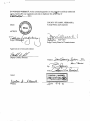
Dated this
Moved by
Carried.
IL}-t:b.
:BU,S+i
day ofDCember ,2010.
+.}i I-<e..
, and seconded b;r(M t:", )elLu.d~ that the above Resolution be adopted.
NAYS:
ABSENT:
b;tSY\Q..,
Y\pN.
ABSTAIN:
Approved as to for~ and7~t:
~,f~
Sarpy County Deputy Attorney
AGREEMENT
This Agreement is entered into by and between the County of Sarpy, in the State of
Nebraska, a body politic and corporate, and hereinafter "County", and Dakota Security Systems,
Inc., hereinafter "Vendor".
WHEREAS, County is desirous of contracting for Cameras and Card Readers for the
Sarpy County Law Enforcement Center; and,
WHEREAS, the Vendor has been awarded this Agreement as a result of the bid made by
V endor in response to the Specifications and Request for Proposals prepared by County;
NOW, THEREFORE, for and in consideration of the declarations and mutual promises
and covenants contained herein, the County and Vendor agree as follows:
I.
DUTIES OF VENDOR:
A.
Services to be rendered by Vendor under this Agreement shall be all those
services necessary and proper for the installation and materials for Cameras and
Card Readers in conformity with each and every term, condition, specification,
and requirement of the Bid Specifications and the Bid submitted by the Vendor.
B.
All provisions of each document and item referred to in Paragraph A above shall
be strictly complied with the same as if rewritten herein, and in the event of
conflict among the provisions of said documents, the provisions most favorable to
the County shall govern.
C.
Prior to the commencement of any work, Vendor will place on file with the Sarpy
County Clerk, the required certificates of insurance, if applicable.
D.
The Vendor agrees to comply with the residency verification requirements of Neb.
Rev. Stat. §4-108 through §4-114. The Vendor is required and hereby agrees to
use a federal immigration verification system to determine the work eligibility
status of new employees physically performing services within the State of
Nebraska. A federal immigration verification system means the electronic
verification of the work authorization program authorized by the Illegal
Immigration Reform and immigrant Responsibility Act of 1996,8 U.S.C. 1324a,
known as the E-Verify Program, or an equivalent federal program designated by
the United States Department of Homeland Security or other federal agency
authorized to verify the work eligibility status of a newly hired employee.
If the Vendor is an individual or sole proprietorship, the following applies:
1.
The Vendor must complete the United States Citizenship Attestation
Form, available on the Department of Administrative Services website at
www.das.state.ne.us.
E.
2.
H the Vendor indicates on such attestation form that he or she is a
qualified alien, the Vendor agrees to provide the u.s. Citizenship and
Immigration Services documentation required to verify the Vendor's
lawful presence in the United States using the Systematic Alien
Verification for Entitlements (SA VE) Program.
3.
The Vendor understands and agrees that lawful presence in the United
States is required and the Vendor may be disqualified or the contract
terminated if such lawful presence cannot be verified as required by Neb.
Rev. Stat. Sect. 4-108.
Vendor will submit an invoice to County for work completed based on the
amounts specified in Vendor's bid. Such invoices shall be submitted to:
Beth Cunard
Sarpy County Purchasing
1210 Golden Gate Drive
Papillion, NE 68046
F.
II.
The County and Vendor hereto specifically acknowledge, stipulate and agree that
each and every term of the Bid Specifications and the Vendor's bid constitutes an
essential term of this Agreement, and that, therefore, any violation of any term,
condition, provision, or requirement constitutes a material breach hereunder, for
which County shall have every right under the law to terminate this Agreement,
and obtain any and all relief necessary.
DUTIES OF COUNTY:
In return for full, faithful and diligent rendering of services set forth above, County agrees
to pay to Vendor the amount specified in Vendor's bid upon submission of the required
invoice and satisfactory completion of all required work.
III.
BREACH:
Should Vendor breach, violate, or abrogate any term, condition, clause or provision of
this agreement, the County shall notify Vendor in writing that such an action has
occurred. H satisfactory provision does not occur within ten (10) days from such written
notice, the County may, at its option, terminate this agreement and obtain an alternate
provider to provide all required materials. This provision shall not preclude the pursuit of
other remedies for breach of contract as allowed by law.
,
"
SAVINGS CLAUSE:
This Agreement shall be interpreted, construed and enforced under the laws of the State
of Nebraska. It is understood and agreed by the County and Vendor hereto that if any
part, term, condition, or provision of this Agreement is held to be illegal or in conflict
with any law of the State of Nebraska or of the United States, the validity of the
remaining parts, terms, conditions, or provisions shall not be affected, and the rights and
obligations of the County and Vendor shall be construed and enforced as if the
Agreement did not contain the particular part, term, condition, or provision held to be
invalid.
SCOPE OF AGREEMENT
This Agreement, along with the Bid Specifications, and Bid by Vendor contains the entire
Agreement between the County and Vendor, and there are no other written or oral
promises, contracts or warrants which may affect it. This Agreement cannot be amended
except by written agreement of both the County and Vendor. Notice to the County and
Vendor shall be given in writing to the agents for each party named below:
County:
Ms. Debra Houghtaling
Clerk of Sarpy County
1210 Golden Gate Drive
Papillion, NE 68046
Vendor:
Mr. Matt Vellek
Dakota Security Systems, Inc.
12020 Shamrock Plaza, Suite 200
Omaha, NE 68154
~
,
.,
IN WITNESS WHEREOF, we the contracting parties, by our res~ctive and duly authorized
ac;:' hereto affix our signatures and seals in duplicate this ~ day of
,2010.
, t'e.Yhber
(Seal)
COUNTY OF SARPY, NEBRASKA,
A body Politic and Corporate
ATTEST:
OJ.lYu. ( ,a,--'\~
e on Id.-) /4/10
Sarpy County Board of Commissioners
Approved as to form and content:
Deputy County Attorney
Vendor:
By:
Attest:
r:.E
J_SE~AL. i:~l!~~
~I
SOUTH DAKOTA
+~,..,c"':II"":f,.,c.e:pIGrf:JI~.,,.lft,+
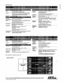
Bid Opening:
2:00 p.m., Thursday
December 2,2010
Bid Tab
Cameras Card Readers
for the
Law Enforcement Center
Electronic Engineering
Unit Price Extended Price
Quantity
Option 1 - Card Reader_System
DSX·1048PKG
DSX LAN Module
Card Readers with Request to Exit
Card Readers
Contact Switches
Labor
Option 1 Subtotal
Option 2 - Cameras
Toshiba IK-WB30A
Toshiba IK-WRI2A
Axis ZX1755·E
Toshiba Network Video Recorder
Labor
Option 2 Subtotal
Option 3 - Card Reader System - Garage
DSX LAN Module
Request to Exit and Door Position
Contact Switches
Labor
Option 3 Subtotal
$607.10
$711.10
$2,228.20
$8,716.50
1
3
3
Sierra Detention Systems
Unit Price Extended Price
$13,416.00
$344.00
$4,320.00
$280.00
$128.00
$10,670.00
$29,158.00
$3,565.00
$295.00
$230.00
$165.00
$8.00
$10,695.00
$295.00
$3,680.00
$330.00
$128.00
$8,000.00
$23,128.00
$3,900.00
$300.00
$260.00
$211.00
$5.00
$11,700.00
$300.00
$4,160.00
$422.00
$80.00
$11,818.00
$28,480.00
$3,642.60
$6,399.90
$4,456.40
$8,716.50
$12,575.00
$35,790.40
$683.33
$1,358.45
$2,186.00
$8,498.17
$4,099.98
$12,226.05
$4,372.00
$8,498.17
$9,450.00
$38,646.20
$670.00
$970.00
$1,825.00
$8,468.00
$4,020.00
$8,730.00
$3,650.00
$8,468.00
$8,120.00
$32,988.00
$685.00
$1,169.00
$2,994.00
$10,625.00
$4,110.00
$10,521.00
$5,988.00
$10,625.00
$9,972.00
$41,216.00
$0.00
$0.00
$0.00
$344.00
$199.00
$8.00
$344.00
$597.00
$24.00
$1,040.00
$2,005.00
$295.00
$85.00
$8.00
$295.00
$255.00
$24.00
$2,400.00
$2,974.00
$300.00
$55.00
$5.00
$300.00
$165.00
$15.00
$2,490.00
$2,970.00
No Bid
6
9
2
1
Safe-N-Secure
Unit Price Extended Price
$4,472.00
$344.00
$270.00
$140.00
$8.00
$0.00
$0.00
$0.00
$0.00
$0.00
3
1
16
2
16
Security Equ~ment Inc.
Unit Price Extended Price
No Bid
I
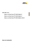
Total
_._-
$69,809.20 .
$59,090.00
$72,666.00
~
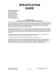
Bid Opening:
2:00 p.m., Thursday
December 2,2010
Bid Tab
Cameras Card Readers
forlhe
Law Enforcement Center
Dakota Security Systems
Unit Price Extended Price
Quantity
Option 1 - Card Reader System
DSX-1048PKG
DSX LAN Module
Card Readers with Request to Exit
Card Readers
Contact Switches
Labor
Option 1 Subtotal
Option 2 - Cameras
Toshiba IK·WB30A
Toshiba IK·WR12A
Axis ZX1755-E
Toshiba Network Video Recorder
Labor
Option 2 Subtotal
Option 3 - Card Reader System - Garage
DSX LAN Module
Request to Exit and Door Position
Contact Switches
Labor
Ofltlon 3 Subtotal
3
1
16
2
16
$2,620.32
$189.00
$273.10
$115.52
$0.00
Control Masters, Inc.
Johnson Hardware
Unit Price Extended Price Unit Price Extended Price
$7,860.96
$189.00
$4,369.60
$231.04
$0.00
$11,839.50
$24,490.10
$2,808.00
$216.00
$187.00
$187.00
$8.00
6
9
2
1
$444.73
$774.72
$1,571.47
$6,223.00
$2,668.38
$6,972.48
$3,142.94
$6,223.00
$10,009.36
$29,016.16
$473.00
$626.00
$1,991.00
$14,064.00
1
3
3
$189.00
$247.85
$0.00
$189.00
$743.55
$0.00
$2,714.00
$3,646.55
$216.00
$187.00
$8.00
$8,424.00
$216.00
$2,992.00
$374.00
$128.00
$12,163.00
$29,962--
$2,838.00
$680.33
$5,634.00 $1,121.33
$3,982.00 $2,072.50
$14,064.00 $10,459.00
$6,586.00
$37,417--
$216.00
$561.00
$24.00
$2,521.00
$4,347--
Miller Electric Co.
Unit Price Extended Price
$0.00 $1,660.00
$0.00 $1,289.00
$0.00
$453.00
$0.00
$411.00
$0.00
$3.60
No Bid
$4,081.98
$646.00
$10,091.97 $1,146.00
$4,145.00 $2,737.00
$10,459.00 $8,498.00
$11,019.00
$39,796.95
$0.00 $1,289.00
$0.00
$369.00
$3.60
$0.00
No Bid
$4,980.00
$1,289.00
$7,248.00
$822.00
$57.60
$12,330.00
$26,726.60
$2,975.30
$225.00
$196.79
$130.99
$15.86
$8,925.90
$225.00
$3,148.64
$261.98
$253.76
$11,061.41
$23,876.69
$3,876.00
$555.39
$10,314.00
$826.01
$5,474.00 $1,794.26
$8,498.00 $10,641.49
$9,450.00
$37,612.00
$3,332.34
$7,434.09
$3,588.52
$10,641.49
$9,821.54
$34,817.98
$1,289.00
$1,107.00
$10.80
$1,935.00
$4,341.80
I
Total
$57,152.81
Prime Communications
Unit Price Extended Price
$225.00
$197.40
$47.58
$1,932.97
$2,402.95
$225.00
$65.80
$15.86
I
$71,726.00
$68,680.40
$61,097.62
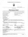
THE AMERICAN INSTITUTE OF ARCHITECTS
II
Bond No. NEC 57300
AlA Document A312
Performance Bond
Any singular reference to Contractor, Surety, Owner or other party shall be considered plural where applicable.
CONTRACTOR (Name and Address):
SURETY (Name and Principal Place of Business):
Dakota Security Systems, Inc.
Merchants Bonding Company (Mutual)
2201 East 54th Street North
2100 Fleur Drive
Des Moines, IA 50321-1158
Sioux Falls, SO 57104
OWNER (Name and Address):
County of Sarpy
1210 Golden Gate Drive
Papillion, NE 68046
CONSTRUCTION CONTRACT
Date: January 3, 2011
Amount: $61,384.20
Sixty One Thousand Three Hundred Eighty Four Dollars and 20/100
Description (Name and Location): Cameras and Card Readers for the Sarpy County Law Enforcement
Center
BOND
Date (Not.earlier than Construction Contract Date): January 4, 2011
Amount: $61,384.20
Sixty One Thousand Three Hundred Eighty Four Dollars and 20/100
Modifications to this Bond:
I!l None
0 See Page 3
CONTRACTOH AS PRINCIPAL
Company:
(Corporate Seal)
SURETY
Company:
(Corporate Seal)
Merchants Bonding Company (Mutual)
Signature: _~~~~~~~~=-Name and Title:
I ,
11'1
II
___
(FOR INFORMA T/ON ONL Y - Name, Address and Telephone)
AGENT or BROKER:
Holmes Murphy & Associates, Inc.
5120 S. Solberg Avenue
Sioux Falls, SO 57108
605-336-1090
~~ ~
Signature:
Name and TltlE;KirntJerll"Own
Attorney-in-Fact
OWNER'S REPRESENTATIVE
(Architect, Engineer or other
party) .'
AlA DOCUMENT A312. PERFORMANCE BOND AND PAYMENT BOND. DECEMBER 1984 ED .• AlA ®
THE AMERICAN INSTITUTE OF ARCHITECTS. 1735 NEW YORK AVE., NW .. WASHINGTON. D.C. 20006
THIRD PRINTING. MARCH 1987
A312-1984
1
1 The Contractor and the Surety. jointly and severally,
bind themselves, their heirs, executors, administrators,
successors and assigns to the Owner for the performance
of the Construction Contract, which is incorporated herein
by reference.
2 If the Contractor performs the Construction Contract,
the Surety and the Contractor shall have no obligation
under this Sond, except to participate in conferences as
provided in Subparagraph 3.1.
3 If there is no Owner Default, the Surety's oblig.Uion
under this Bond shall arise alter:
3.1 The Owner has notified the Contractor and the
Surety at its address described in Paragraph 10 below
that the Owner is considering declaring a Contractor
Default and has requested and attempted to arrange a
conference with the Contractor and the Surety to be
held not later than fifteen days afler receipt of such
notice to discuss methods of performing the Construction Contract. If the Owner, the Contraclor and the
'Surety agree, the Contractor shall be <lUowed a reasonable time 10 perform the Construction Contract, bul
such an agreement shall not waive the Owner's right, if
any, subsequently to declare a: Contr<lctor Default; and
3.2 The Owner has declared a ConlraClor Default and
formally terminated the Contractor's right to complete
the contr<lci. Such Contractor Default shall not be de·
dared e<lrlier than twenty days after the Contractor and
the Surety have received notice as provided in Sub·
paragraph 3.1; and
3.3 The Owner has agreed to pay Ihe Balance ot the
Contract Price to the Surety in accordance with the
terms of the Construction Contract or to a contractor
selected 10 perform the Construction Contract in accordance with the terms of the contract wilh the Owner.
4 When the Owner has satisfied Ihe conditions of Para·
graph 3, the Surety shall promptly and at the Surety's expense take one of the following actions:
4.1 Arrange for the Contractor, with consent of the
Owner, to perform and complete the Construction
Contract~ or
4.2 Undertake to perform and complete the Construction Contract itself, through its agents or through inde·
pendent contractors; or
4.3 Obtain bids or negotiated proposals from
qualified contractors acceptable to the Owner for a
contract for performance and completion of the Con·
struction Contract. arrange for a contract to be pre·
pared for execution by the Owner and the contractor
selected with Ihe Owner's concurrence, to be secured
with performance and payment bonds executed by a
qualified surety equivalent to the bonds issued on the
Construction Contract. and pay 10 the Owner the
amount of damages as described in Paragraph 6 in excess of the Balance of thc Contract Price incurred by the
Owner resulting from the Conlractor's default; or
4.4 Waive its right 10 perform and complete, arrange
for completion. or obtain a new contractor and with
reasonable promptness under the circumstances!
.1
After investigation, determine the amount for
which it may be liable to the Owner and, as
soon as practicable .-siler the amount Is determined, tender payment therefor to the
Owner; or
.2 Deny liability in whore or in part and notify the
Owner citing reasons therefor.
S If the Surety does not proceed as provided in Paragraph
4 with reasonable promptness, the Surety shaU be deemed
to be in default on this Bond fiheen days afler receipt of an
additional written notice from the Owner to the Surety
demanding that the Surely perform its obligations under
this Bond, and the Owner shall be entitled to enforce an\'
remedy available to the Owner. If the Surety prO('eeds
provided in Subparagraph 4.4, and the Owner refuses the
payment tendered or the Surety has denied liability, in
whole or in part, without further notice the Owner shall be
entitled to enforce any remedy availab~e to the Owner.
as
6 After the (hvner has terminated the Conlr&lctor's righl
to complete the Construction Contract, and if the Surety
elects to act under Subparagraph 4.1, 4.2. or 4.3 above,
then the responsibilities of the Surety to Ihe Owner Sh.lll
not be greater Ihan those of the Contractor under the
Construction Contract, and the responsibilities of the
Owner to the Surety shaU not be greater than those of the
, Owner under the Construction Contract. To the limit of the
amount of this Bond. bul subject to commitment by the
Owner of the Balance of the Contract Price to mitigation of
costs and damages on the Construction Contract, the Surety is Obligated without duplication for:
6.1 The responsibilities of the Contractor for cortee·
tion of defective work and completion or the Construction Contract;
6.2 Additional legal. design profeSsional and delay
costs resulting from the Contractor'S Default, and resulting from the actions or failure to act of the Surety
under Paragraph 4; and
6.3 liquidated damages, or if no liquidated damages
are specified in the Construction Conrracl, actual dam·
ages caused by delayed performance or non-perlor'
mance of the Contractor.
7 The Surety shall not be liable to the Owner or others for
obligations of the COntractor thaI are unrelated to the Con·
s.ructlon Contract. and the Balance of the Contract Price
shall not be reduced or set off on account of any such
unrelated obligations. No right of acSion shall aCCrue on
this Bond 10 any per!'ion or entity other than the Owner Of
its heirs, executors, administrators or successors.
8 The Surety hereby waives notice of any change. inc:lud·
ing changes of time. to the Construction Contract or co
related subcontracts, purchase orders and other obligations.
9 Any proceeding, legal or equitable, under this Bond
may be instituted in any court ot competent jurisdiction in
the location in which the work or part olthework is located
and shall be instituted within two years after Contractor
Default or within Iwo years after the Contractor ceased
working or within two years after the Surety refuses or fails
to perform ilS obligations under this Bond, whichever occurs first. If the provisions of this Paragraph are void or
prohibited by law, the minimum period of limilation avail-
AlA DOCUMENT A312. PERFORMANCE BOND AND PAYMENT BOND. DECEMBER 1984 ED .• AlA ®
THE AMERICAN INSTITUTE OF ARCHITECTS, 1735 NEW YORK AVE., N.W., WASHINGTON, D.C. 20006
THIRD PRINTING. MARCH 1987
A312-1984
Z
able to sureties as a defense in the jurisdiction of the suit
shall be applicable.
10 Notice to the Surety, the Owner or the Contractor shall
be mailed or delivered to the address shown on the signature page.
11 When this Bond has been furnished to comply with a
statutory or other legal requirement in the location where
the construction was to be performed, any provision in this
Bond conflicting with said statutory or legal requirement
shall be deemed deleted herefrom and provisions conforming to such statutory or other legal requirement shall
be deemed incorporated herein. The intent is that this
Bond shall be construed as a statutory bond and not as a
common law bond.
12 DEFINITIONS
12.1 Balance of the Contract Price: The total amount
payable by the Owner to the Contractor under the
Construction Contract after all proper adjustments
have been made, including allowance to the Con-
tractor of any amounts received or to be received by
the Owner in settlement of insurance or other claims
for damages to which the Contractor is entitled, reduced by all valid and proper payments made to or on
behalf of the Contractor under the Construction Contract.
12.2 Construction Contract: The agreement between
the Owner and the Contractor identified on the signature page. including all Contract Documents and
changes thereto.
12.3 Contractor Default: Failure of the Contractor.
which has neither been remedied nor waived, to perform or otherwise to comply with the terms of the
Construction Contract.
12.4 Owner Default: Failure of the Owner, which has
neither been remedied nor waived. to pay the Contractor as required by the Construction Contract or to
perform and complete or comply with the other terms
thereof.
MODIFICATIONS TO THIS BOND ARE AS fOllOWS:
(Space is provided below for additional signatures of added parties, other than those appearing on the cover page.)
CONTRACTOR AS PRINCIPAL
Company:
SURETY
(Corporate Seal)
Company:
(Corporate Seal)
I,
,I
iI,1
I
I
Signature: _ _ _ _ _ _ _ _ _ _ _ _ _ _ __
Name and Title:
Address:
Signature: _ _ _ _ _ _ _ _ _ _ _ _ _ __
Name and Title:
Address:
AlA DOCUMENT A312. PERFORMANCE BOND AND PAYMENT BOND. DECEMBER 1984 ED .• AlA ®
THE AMERICAN INSTITUTE OF ARCHITECTS, 1735 NEW YORK AVE., NW., WASHINGTON, D.C. 20006
THIRD PRINTING. MARCH 1987
A312-1984
3
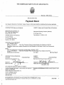
THE AMERICAN INSTITUTE OF ARCHITECTS
Bond No. NEC 57300
AlA Document A312
Payment Bond
II
Any singular reference to Contractor, Surety, Owner or other party shall be considered plural where applicable.
II
'1'1
1
CONTRACTOR (Name and Address):
SURETY (Name and Principal Place of Business):
Dakota Security Systems, Inc.
2201 East 54th Street North
Sioux Falls, SD 57104
2100 Fleur Drive
OWNER (Name and Address):
Des Moines, IA 50321-1158
Merchants Bonding Company (Mutual)
County of Sarpy
1210 Golden Gate Drive
Papillion, NE 68046
CONSTRUCTION CONTRACT
Date: January 3, 2011
Amount: $61,384.20
Sixty One Thousand Three Hundred Eighty Four Dollars and 20/100
Description (Name and location):Cameras and Card Readers for the Sarpy County law Enforcement
Center
BOND
Date (Not earlier than Construction Contract Date): January 4, 2011
Amount: $61,384.20
Sixty One Thousand Three Hundred Eighty Four Dollars and 20/100
Modifications to this Bond:
0 None
00 See Page 6
,
II
II
: 11,1
I
'I'
CONTRACTOR AS PRiNCIPAL
Corr.pany:
Dakota Security Systems, Inc.
Signature
Name and Title:
(Corporate Seal)
~£
SURETY
Company:
(Corporate Seal)
Merchants Bonding Company (Mutual)
~~~~t~~~it;~ow~
Attorney-in-Fact
(Any additional signatures appear on page 6)
(FOR INFORMA TlON ONL Y - Name, Address and Telephone)
AGENT or BROKER:
Holmes Murphy & Associates, Inc.
5120 S. Solberg Avenue
Sioux Falls, SD 57108
605-336-1090
OWNER'S REPRESENTATIVE (Architect, Engineer or other
party) :
AlA DOCUMENT A312. PERFORMANCE BOND AND PAYMENT BOND. DECEMBER 1984 ED .• AlA ®
THE AMERICAN INSTITUTE OF ARCHITECTS, 1735 NEW YORK AVE .• N.W., WASHINGTON, D.C. 20006
THIRD PRINTING. MARCH 1987
'I,I'
, III!
- -
- _. .
--------------
A312-1984
4
1 The Contractor and the Surety, jointly and severally,
bind themselves, their heirs, executors, administrators,
successors and assigns to the Owner to pay for labor,
materials and equipment furnished for use in the
performance of the Construction Contract, which is
incorporated herein by reference.
2 With respect to the Owner, this obligation shall be null
and void if the Contractor:
2.1 Promptly makes payment, directly or indirectly, for
all sums due Claimants, and
2.2 Defends, indemnifies and holds harmless the
Owner from claims, demands, liens or suits by any
person or entity whose claim, demand, lien or suit is for
the payment for labor. materials or equipment furnished
for use in the performance of the Construction Contract,
provided the Owner has promptly notified the
Contractor and the Surety (at the address described in
Paragraph 12) of any claims, demands, liens or suits
and tendered defense of such claims, demands, liens
or suits to the Contractor and the Surety, and provided
there is no Owner Default.
Ii
~'I
II
3 With respect to Claimants, this obligation shall be null
and void if the Contractor promptly makes payment,
directly or indirectly, for all sums due.
4. The Surety shall have no obligation to Claimants under
this Bond until:
4.1 Claimants who are employed by or have a direct
contract with the Contractor have given notice to the
Surety (at the address described in Paragraph 12) and
sent a copy, or notice thereof, to the Owner, stating that
a claim is being made under this Bond and, with
substantial accuracy, the amount of the claim.
4.2 Claimants who do not have a direct contract with
the Contractor:
Ii
,
,1.1
II
r
.1 Have furnished written notice to the Contractor
and sent a copy, or notice thereof, to the
Owner, within 90 days after having last
performed labor or last furnished materials or
equipment included in the claim stating, with
substantial accuracy, the amount of the claim
and the name of the party to whom the
materials were furnished or supplied or for
whom the labor was done or performed; and
.2 Have either received a rejection in whole or in
part from the Contractor, or not received within
30 days of furnishing the above notice any
communication from the Contractor by which
the Contractor has indicated the claim will be
paid directly or indirectly; and
.3 Not having been paid within the above 30
days, have sent a written notice to the Surety
(at the address described in Paragraph 12)
and sent a copy, or notice thereof, to the
Owner, stating that a claim is being made
under this Bond and enclosing a copy of the
previous written notice furnished to the
Contractor.
5 If a notice required by Paragraph 4 is given by the
Owner to the Contractor or to the Surety, that is sufficient
compliance.
6 When the Claimant has satisfied the conditions of
Paragraph 4, the Surety shall promptly and at the Surety's
expense take the following actions:
6.1 Send an answer to the Claimant, with a copy to the
Owner, within 45 days after receipt of the claim, stating
the amounts that are undisputed and the basis for
challenging any amounts that are disputed.
6.2 Payor arrange for payment of any undisputed
amounts.
7 The Surety's total obligation shall not exceed the
amount of this Bond, and the amount of this Bond shall be
credited for any payments made in good faith by the
Surety.
8 Amounts owed by the Owner to the Contractor under the
Construction Contract shall be used for the performance of
the Construction Contract and to satisfy claims, if any, under
any Construction Performance Bond. By the Contractor
furnishing and the Owner accepting this Bond, they agree
that all funds earned by the Contractor in the performance of
the Construction Contract are dedicated to satisfy
obligations of the Contractor and the Surety under this
Bond, subject to the Owner's priority to use the funds for the
completion of the work.
9 The Surety shall not be liable to the Owner, Claimants or
others for obligations of the Contractor that are unrelated to
the Construction Contract. The Owner shall not be liable for
payment of any costs or expenses of any Claimant under
this Bond, and shall have under this Bond no obligations to
make payments to, give notices on behalf of, or otherwise
have obligations to Claimants under this Bond.
10 The Surety hereby waives notice of any change,
including changes of time, to the Construction Contract or to
related subcontracts, purchase orders and other obligations.
11 No suit or action shall be commenced by a Claimant
under this Bond other than in a court of competent
jurisdiction in the location in which the work or part of the
work is located or after the expiration of one year from the
date (1) on which the Claimant gave the notice required by
Subparagraph 4.1 or Clause 4.2.3, or (2) on which the last
labor or service was performed by anyone or the last
materials or equipment were furnished by anyone under the
Construction Contract, whichever of (1) or (2) first occurs. If
the provisions of this Paragraph are void or prohibited by
law, the minimum period of limitation available to sureties as
a defense in the jurisdiction of the suit shall be applicable.
12 Notice to the Surety, the Owner or the Contractor shall
be mailed or delivered to the address shown on the
Signature page. Actual receipt of notice by Surety, the
Owner or the Contractor, however accomplished, shall be
sufficient compliance as of the date received at the address
shown on the signature page.
13 When this Bond has been furnished to comply with a
statutory or other legal requirement in the location where the
construction was to be performed, any provision in this Bond
"
II
AlA DOCUMENT A312. PERFORMANCE BOND AND PAYMENT BOND. DECEMBER 1984 ED .• AlA ®
I'
'1,1
I!
THE AMERICAN INSTITUTE OF ARCHITECTS, 1735 NEW YORK AVE .. NW., WASHINGTON, D.C. 20006
THIRD PRINTING. MARCH 1987
A312-1984
5
conflicting with said statutory or legal requirement shall be
deemed deleted herefrom and provisions conforming to
such statutory or other legal requirement shall be deemed
incorporated herein. The intent is that this Bond shall be
construed as a statutory bond and not as a common law
bond.
II
service or rental equipment used in the Construction
Contract, architectural and engineering services
required for performance of the work of the Contractor
and the Contractor's subcontractors, and all other
items for which a mechanic's lien may be asserted in
the jurisdiction where the labor, materials or
equipment were furnished.
14 Upon request by any person or entity appearing to be a
potential beneficiary of this Bond, the Contractor shall
promptly furnish a copy of this Bond or shall permit a copy
to be made.
15.2 Construction Contract:
The agreement
between the Owner and the Contractor identified on
the signature page, including all Contract Documents
and changes thereto.
15 DEFINITIONS
I,
15.3 Owner Default: Failure of the Owner, which has
neither been remedied nor waived, to pay the
Contractor as required by the Construction Contract or
to perform and complete or comply with the other
terms thereof.
15.1 Claimant: An individual or entity having a direct
contract with the Contractor or with a subcontractor of
the Contractor to furnish labor, materials or equipment
for use in the performance of the Contract. The intent
of this Bond shall be to include without limitation in the
terms "labor, materials or equipment" that part of
water, gas, power, light, heat, oil, gasoline, telephone
j'
:1'11
MODIFICATIONS TO THIS BOND ARE AS FOLLOWS:
§ 6 When the Claimant has satisfied the conditions of Section 4, the Surety shall promptly and at the
Surety's expense take the following actions:
§ 6.1 Send an answer to the Claimant, with a copy to the Owner, within #60 days after receipt of the claim,
stating the amounts that are undisputed and the basis for challenging any amounts that are disputed.
I'
§ 6.2 Payor arrange for payment of any undisputed amounts.
§ 6.3 The Surety's failure to discharge its obligations under this Section 6 shall not be deemed to constitute
a waiver of defenses the Surety or Contractor may have or acquire as to a claim. However. if the Surety
fails to discharge its obligations under this Section 6, the Surety shall indemnify the Claimant for the
reasonable attorney's fees the Claimant incurs to recover any sums found to be due and owing to the
Claimant.
II
,,
iH
I'
(Space is provided below for additional signatures of added parties, other than those appearing on the cover page.)
SURETY
CONTRACTOR AS PRINCIPAL
Company:
(Corporate Seal)
Signature: _ _ _ _ _ _ _ _ _ _ _ _ _ __
Name and Title:
Address:
Company:
(Corporate Seal)
Signature: _ _ _ _ _ _ _ _ _ _ _ _ _ __
Name and Title:
Address:
AlA DOCUMENT A312. PERFORMANCE BOND AND PAYMENT BOND. DECEMBER 1984 ED .• AlA ®
THE AMERICAN INSTITUTE OF ARCHITECTS, 1735 NEW YORK AVE., N.W., WASHINGTON, D.C. 20006
THIRD PRINTING. MARCH 1987
I'
A312-1984
6
,
•
.
MERCHAN~
BONDING COMPANY
I
POWER OF ATTORNEY
Ii
Know All Persons By These Presents, that the MERCHANTS BONDING COMPANY (MUTUAL), a corporation duly organized under
the laws of the State of Iowa, and having its principal office in the City of Des Moines, County of Polk, State of Iowa, hath made,
constituted and appointed, and does by these presents make, constitute and appoint
Greg A. Krier, Nancy DeNeui, Bonnie Merz, Cheryl Havelaar, Kurt Ratzlaff, Douglas Muth,
Tracey Anderson, Lori Klein, Grace Hatting, Kimberly Brown
Sioux Falls
and State of
South Dakota
its true and lawful Attorney-in-Fact, with full power
of
and authority hereby conferred in its name, place and stead, to sign, execute, acknowledge and deliver in its behalf as surety any
and all bonds, undertakings, recognizances or other written obligations in the nature thereof, subject to the limitation that any such
instrument shall not exceed the amount of:
FIFTEEN MILLION ($15,000,000.00) DOLLARS
and to bind the MERCHANTS BONDING COMPANY (MUTUAL) thereby as fully and to the same extent as if such bond or
undertaking was signed by the duly authorized officers of the MERCHANTS BONDING COMPANY (MUTUAL), and all the acts of
said Attorney-in-Fact, pursuant to the authority herein given, are hereby ratified and confirmed.
This Power-of-Attorney is made and executed pursuant to and by authority of the following Amended Substituted and Restated ByLaws adopted by the Board of Directors of the MERCHANTS BONDING COMPANY (MUTUAL) on November 16, 2002.
ARTICLE II, SECTION 8 - The Chairman of the Board or President or any Vice President or Secretary shall have power and
authority to appoint Attorneys-in-Fact, and to authorize them to execute on behalf of the Company, and attach the Seal of the
Company thereto, bonds and undertakings, recognizances, contracts of indemnity and other Writings obligatory in the nature
thereof.
ARTICLE II, SECTION 9 - The signature of any authorized officer and the Seal of the Company may be affixed by facsimile
to any Power of Attorney or Certification thereof authorizing the execution and delivery of any bond, undertaking,
recognizance, or other suretyship obligations of the Company, and such signature and seal when so used shall have the
same force and effect as though manually fixed.
II
In Witness Whereof, MERCHANTS BONDING COMPANY (MUTUAL) has caused these presents to be signed by its President and
its corporate seal to be hereto affixed, this 23rd day of December, 2010.
........ -.
• ' \\lG CO~·
.'~~......... ~",4".
..~ .. ~\\PO~';""~"
:,_. ~
......... ;..L.
-.... ot"",..
I
11,1
I,
:~:-
............
".
0:-.:~:
-0-
. .....
~iV' .... "'\"":.'
• "",".
• .........
1933
••.::;:t •
......'-.
~.
STATE OF IOWA
COUNTY OF POLK ss.
'. ........
~
MERCHANTS BONDING COMPANY (MUTUAL)
BY~7~
President
On this 23rdday of December, 2010 , before me appeared Larry Taylor, to me personally known, who being by me duly sworn did say that
he is President of the MERCHANTS BONDING COMPANY (MUTUAL), the corporation described in the foregoing instrument, and that the
Seal affixed to the said instrument is the Corporate Seal of the said Corporation and that the said instrument was signed and sealed in behalf
of said Corporation by authority of its Board of Directors.
In Testimony Whereof, I have hereunto set my hand and affixed my Official Seal at the City of Des Moines, Iowa, the day and year first
above written.
~
•
,'t
o •
w
CINDY SMYTH
Commission Number 173504
My Commission Expires
March 16. 2012
Cu~~
Notary Public, Polk County, Iowa
STATE OF IOWA
COUNTY OF POLK ss.
II
II
I, William Warner, Jr., Secretary of the MERCHANTS BONDING COMPANY (MUTUAL), do hereby certify that the above and foregoing
is a true and correct copy of the POWER-OF-ATIORNEY executed by said MERCHANTS BONDING COMPANY (MUTUAL). which is
still in full force and effect and has not been amended or revoked.
In Witness Whereof, I have hereunto set my hand and affixed the seal of the Company on this 4th
:1'1
..... -.
• ' :\\lG co;~·
.'~~""""<"~'•
..~~.. ~\\PO.-9~""~'.
• ,_:~
" ......... ;..L.
• -.. :ot"",..
:;:-
.
•• "",:.
.......
~.
POA 0001 (1/09)
- - -
-
_._--------
-0-
1933
c:-.
3::
•: c:::- •
.~.
'. ~"
.. ,J..~ •
••••
~JV"'"'' ,,,.....
{::t
.-
.......
day of January
• 2011 .
V~g~~,
Secretary
II,
~
.
""'~,:;,'~""-;~'
·s~·
~
~',..-----------,---,------,
-_.~,~. ", --- - .- -'
. ,\~,
~~.
"
. \ " ~~. ,.;m.':w:
~
;.
'"
.,b'l<
;
~
"
r
f"
.
,
.
.
\""'".,
.
Mike Abraham
.ecuri ty
.
Regional Account Manager,
SYSTEMS, INC.
.
I
,..
~12020 Shamrock Plaza . ,
Suit~200
Omaha, NE 68154
402.778.5081 ext. 353
-800j65.562-5
,- ,
cell:
402.981.4417
\
e-mail: ·[email protected] ':
web:
www.dakotasecurity.coml~
office:
\~~4!k~~~:
\~
,.~~
~\
, I'
.'
'/
·7
b~\) ~\O'\)9 \\+4tl'~j
5a.rp~ COc..>Nt-y 8,oa. r cl £'uSiN~S.5
\ ~\d GoLJe.tJ GG.~e bn...\ve.
? 0.
f i \\ i "\t-l ~
0
(,,'2, D4; (0
I
IiI
.
-~\
."
o Pb'vJ \N &- - :2:,00 P, M \T~o"'sJa.y' t
'1,-'
Dec~I'"'\b-e1L 2 \ '20 (0. ~(,
.J. .
.
. ,,:,
::.
.
~
"',
"
.
I,
TABLE OF CONTENTS
Cover
Bid Form - Sarpy County Cameras and Card Readers
OPTION 1 - Card Reader System
Bid Form - Sarpy County Cameras and Card Readers
OPTION 2 - Cameras
Bid Form - Sarpy County Cameras and Card Readers
OPTION 3 - Card Reader System - Garage
Bid Form - References, Addendums Acknowledgement, Company
Information
Dakota Security Systems, Inc. Proposal Factors Summary List
Manufacture's Specification Information
•
•
•
DSX Access Systems - Dakota Security Systems, Inc. Authorized and
Factory Trained Dealer Letter
Access Control System - Card Readers
Video System - Cameras
Dakota Security Systems, Inc. Company Information
•
•
•
•
•
•
Experience
We know Government Security
We know the Steps to Security
Dakota Security Systems, Inc. Quality Assurance Program
Dakota Security Systems, Inc. Change Management Process
Dakota Security Systems, Inc. - Why Choose Us?
Dakota Security Systems, Inc. Proposal
Sarpy County Nebraska
Law Enforcement Center Project - Cameras & Card Readers
Bid Opening - December 2, 20102:00 PM CST
,
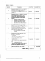
COMPANY NAME: Dakota Security Systems, Inc.
Sarpy County, Nebraska
Cameras and Card Readers
Bid Form
Option 1 - Card Reader System
Quantity
Description
Unit Price
Extended Price
3
PSX-I048PKG which includes:
~ 2,620.32
DSX-I040E Enclosure,
DSX-I040CDM Communication
Distribution Module,
4-1042 Intelligent Controllers, and
DSX 1040 PDP Power Distribution
Panel with emergency recharge
power
batteries, per package.
1
PSX LAN Module
~
189.00
$
189.00
~ard Readers with Request to Exit
~
273.10
$
4,369.65
16
~nd
Door Position Switches
$ 7,860.98
115.52
2
~ard Readers
16
to.L. Listed contact switches
--
Labor (inGludes labor, mise, bonds) -
Option 1 Total
$
$
231.04
Included Above
$ Included Above
----------
$
11,839.50
24,490.17
Card Readers are compatible with the following types of cards:
FlexCard®
FlexlSO®
FlexISO®XT
MIFARE®
DESFire™
iCLASS®
FlexTag™
FlexKey®
P:\l..aw Enforcement Center Relocation\Cameras & Card Readers\Specifications_Security.wpd
16
.,
Option 2 - Cameras
Quantity
6
Description
Unit Price
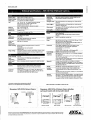
Toshiba IK-WB30A-KlT28-12, 2 megapixel
esolution, color day/night cameras w/
YV43X28SA-SA2 Megapixel Lens 1/3",2.812mm,F1.4
Extended Price
$ 444.73
$ 2,668.40
9
Toshiba IK-WRI2A, 2 megapixel resolution,
l;olor day/night cameras with 3-9 mm
varifocallens. Optional accessories per
instillation requirement of each camera
ocation:
• JK-PHOI2 Outdoor Housing
• JK-PMAI2 Pole Mount Adapter
• JK-WMI2 Wall Mount Adapter
• JK-CMA12 Corner Mount Adapter
~ 774.72
$ 6,972.48
2
Axis Q1755-E 60 Hz, 5 megapixel high
definition camera with f5.1-51mm, F1.8 - 2.1
auto
focus, auto day/night lens. Includes
I
external housing, wall mount bracket, sun
~hield, and 16 ft. Ethernet cable.
• VT POLE MOUNT ADAPTER
WSFPA
$ 1,571.47
~ 3,142.94
~ 6,223.00
~ 6,223.00
-
$
1
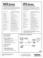
Iroshiba Network Video Recorder, model
NvS32-2T - 32 channel
3GBRAM
Recording rate (30) PPS per camera
Compression MPEG4, H.264
Internal RAID5
(8) TB total hard drive capacity expanded
~ith
• 3 additional HDD-2TB
Includes video manager software, and SCS
~oftware with Embedded Windows XP.
-
Labor (includes labor, misc, bond)
Option 2 Total ~
10,009.36
29,016.18
~.
P:\Law Enforcement Center Reiocation\Cameras & Card Reader.;\Specifications_Security. wpd
17
Option 3 - Card Reader System - Garage
Quantity
Description
Unit Price
Extended Price
1
bsx LAN Module
$ 189.00
$ 189.00
3
Request to Exit and Door Position Switches
$ 247.85
$
3
p.L.Listed contact switches
$ Included Above $ Included Above
--
rL-abor
-
743.57
$ 2,714.00
Option 3 Total ~ 3,646.57
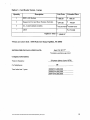
*Prices are to be F.O.B. - 8335 Platteview Road, Papillion, NE 68046
ESTIMATED INSTALLATION DATE:
April 15, 2011 **
"As detailed in specifications, page 8, item 1
Company Information:
Years in business:
# of employees
Total sales last 3 years
P:\Law Enforcement Center Relocation\Cameras & Card Readers\Specificatioos_Security.wpd
34 years (since June 1976)
98
200~1 $13,000,000
20081 $14,000,000
20071 $16,500,000
18
References:
Company Name: Omaha Police Department
Address: 505 South 15th Street Omaha, NE 68102
Contact Name: Captain Adam Kyle
Phone Number: 402-444-5600
Fax Number:
Date of Purchase: 02/01/2009
CompanyName: Concordia University
Address: 800 North Columbia Avenue Seward, NE 68434
Contact Name: John Townsend
Phone Number: 402-643-7286
Fax Number:
Date of Purchase: 03/01/2010
Company Name: University of Nebraska - Omaha
Address: 6001 Dodge Street Omaha, NE 68182
Contact Name: John Larson
Phone Number: _4...!.:0><.!2=--~5~54..!...-.....,2,"",9~2.=.2_ __
Fax Number: _ _ _ _ _ _ _ _ _ _ _ _ Date of Purchase: --=0=2.. ,10<.. .:1c.:/2
. .:=0=-1:....:0'---_ __
I certify that this bid is submitted in accordance with the specifications issued by Sarpy County.
I acknowledge receipt of the following addenda (if applicable):
Addendum # 1
Addendum #2
Attachments:
X
X
-----=--=-----------'--'------
Literature/Cut-sheets
Warranty Information
Dakota Security Systems, Inc.
Company Name
Mike Abraham
Company Representative (Please print)
402-778-5081
Authorized Signature
12020 Shamrock Plaza, Ste 200
Address
Telephone Number
605-271-7001
Fax Number
Omaha, NE 68154
City, State & Zip
[email protected]
E-Mail Address
*NOTE: Sarpy County is tax exempt and will provide the proper form upon request.
P:\Law
Enforcem~t
Center Relocation\Cameras & Card Readers\SpecificatioDS_Security.wpd
19
Dakota Security Systems, Inc. Proposal Factors Summary List
A. Compliance with all requirements - YES.
B. Price - Provided as per RFP.
C. The ability, capability, and skills of vendlor to perform - YES see
Dakota Security Systems, Inc. company information.
D. The character, integrity, reputation, judgment, experience, and
efficiency of the vendor
Excellentsee Dakota Security Systems, Inc. company information.
E. The quality of previous performance - Excellent see Security
Systems, Inc. company information and referell1ces.
F. Weather vendor can perform within time specified - YES see bid
form.
G. The previous and existing compliance of the supplier with laws Excellent see company information and references.
H. The life-cost of the personal property or services in relation to the
purchase price and specified use.
Industry standard, Dakota Security Systems, Inc. bid systems
and products as detailed within the RFP.
I. The life-cost of the personal property or services taking into
consideration any commonly accepted standards tests and
standards of products, service, usability and user requirements
Industry standard, Dakota Security Systems, Inc. bid systems
and products as detailed within the RFP.
J. The energy efficiency ratio as stated by the supplier.
Industry standard, Dakota Security Systems, Inc. bid systems
and products
, as detailed within the RFP.
Continued
K. The life-cycle costs between alternatives for all classes of
equipment. the evidence of expected life. the repair and
maintenance costs and the energy consumption on a
per year basis.
No alternates utilized.
L. Other positive information bearing a decision to award Dakota
Security Systems. Inc. this project.
Dakota Security Systems is an authorized and factory trained dealer
in good standing for DSX Access Systems which is the system
specified in this projects RFP documents and is the current system
utilized by Sarpy County.
Dakota Security Systems is national industry leader with excellent
local references.
Dakota Security Systems, Inc. Proposal
Sarpy County Nebraska
Law Enforcement Center Project - Cameras & Card Readers
Bid Opening - December 2, 2010 2:00 PM CST
DSX ACCESS SYSTEMS, INC.
The Security Professionals' First Choice
November 30,2010
To Whom It May Concern:
This letter is to certify that Dakota Security Systems located in Sioux Falls, South Dakota
is an authorized andfactory trained dealer in good standing for DSX Access Systems. As
such, Dakota Security Systems has committed to maintaining a fully trained sales and
technical staff and will receive the full support and resources that DSX has to offer.
Dakota Security Systems has been a DSX Access Systems dealer since February 2010.
Dakota Security Systems is highly qualified to d~sign,· sell, install and service the
complete line of card access and ID badging products from DSX Access Systems.
DSX Access Systems is pleased to have Dakota Security Systems as a business partner,
and we are confident that any customer will be eminently pleased with the quality of
work and professionalism exhibited by their staff.
If anyone should have any questions regarding this subject please call my office at 888419-8353 extension 142.
Sincerely,
J~~
Scott Bennett
National Sales Manager
10731 Rockwall Road • Dallas, Texas 75238-1219
24l:iour No. (888) 419-8353· (214) 553-6140. Fax (214) 553-6147
www.dsxinc.com
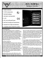
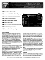
V Scalable Architecture
V TCP/IP Communications
V Individual Intelligence
@-
V 512K RAM / 512K Flash ROM
V UL294
V 150+ Card and Keypad Formats
CE:
V Real Time Processing and Communications
V Integrated Power Supply and Distribution
V Compatible with all existing DSX Controllers
.
I
I
I
'.
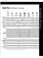
General Information
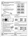
The DSX-1048PKG Intelligent Controller is an independent
processing 8 door package designed to be a cost effective building
block platform that allows expansion in a scalable manner. Up to 8
doors can be controlled from 1 enclosure for an efficient space
saving package. The controllers are strategically placed throughout
the customer location connected together with a two twisted pair
cable. Each DSX-1048 operates as a fully intelligent and independent controller that retains all data necessary for system operation in
its own RAM. With its integral real-time Clock and Calendar it
performs Time Zone control with Holiday overrides for inputs,
outputs, and cards even when communication to the PC or other
controllers is not available.
Controller Architecture
The DSX-I 048 Intelligent Controller may be used in conjunction
with all other DSX Controllers as a Master or Slave in the controller
network. Any controller may be designated as a Master or Slave
controller. The Master or Slave mode of operation is determined by
the panels dip switch settings. The first panel of each location is
designated as the Master while all others would be considered
Slaves. The Master is responsible for communications to the PC and
to the Slave panels. Up to 16 - DSX-1048PKG Intelligent Controllers can be used in a single Location providing for 128 readers.
Multiple Locations can be grouped for systems that require more
than 128 readerslkeypads.
Each DSX-1048PKG includes a DSX-1040E Enclosure, a DSX1040CDM Communication Distribution Module and 4 DSX-1042
Intelligent Controllers. Each DSX-1048 provides 8 Reader Ports, 32
Inputs, and 16 Outputs. Each DSX-I042 has a 12 volt fused power
output for it's Card Readers and Keypads. The DSX-I042 contains
an AM 186 processor, S12K of RAM, S12K of Flash ROM, and a
Real Time Clock. The DSX-1048 allows all door and field ~iring
connections to be made via removable termInal blocks. The DSX1040CDM receives RS-48S communications from a possible
previous panel and regenerates the 4 wire-RS48S to the next DSXl048PKG. The DSX-I040CDM also distributes Slave Controller
communication to those Slave panels located within the same
enclosure.
Used in conjunction with the DSX-1048PKG Intelligent Controller
is a DSX-l 040PDP or Power Distribution Panel. The DSX1040PDP houses the controller and lock power supplies, backup
batteries, and fused power distribution module. The DSX-I 040PDP
is comprised of a DSX-I040PE enclosure, an AS-ISO ISV power
supply for the controllers, an AS-I 00[12] or [24] for either 12V or
24 V locks, and a DSX-1 040PDM or Power Distribution Module.
System Power
Each Controller in the DSX-l 048PKG is powered from an individually fused 12 volt output from the DSX-1040CDM distribution
module located in the same enclosure. The module also provides S
volt power for those Readers and or Keypads that require it. The
DSX-1040CDM receives power from the DSX-1040PDP Power
Distribution Panel. The DSX-1040PDP houses the controller and
lock power supplies" backup batteries, and fused power distribution
module. The DSX-1040PDP is comprised of a DSX-l 040PE
Enclosure, an AS-ISO lSV power supply for the Controllers, an AS-
o
Q
I
,
'
Outputs
100-[12] or [24] for either 12V or 24V locks, and a DSX-1040PDM
Power Distribution Module. The DSX-1040PDM perfonns several
critical functions. First, it takes the 15V power from the AS-150 and
provides an 8 amp fused output to power the DSX-1040CDM which
distributes the power to the DSX-l 042 Controllers in the DSX1048PKG It provides a 12V Battery Charging Circuit to charge
backup batteries for the Controllers. It also provides a charging
circuit for the optional batteries used to backup the 12 or 24 volt lock
power from the AS-I 00 power supply. The Power Distribution
Module has 2 N.O. Relay Outputs, one to signal Loss of AC and one
to signal Low Battery. These Outputs can be connected to spare
Inputs in the DSX-l 048PKG The module also has a Battery Test Input.
This Input when activated shuts off the charging circuit and load
tests the battery for I minute. This Input can be connected to a spare
Output in the DSX-l 048PKG and programmed by time zone to occur
when desired. The DSX-1040PDM routes Lock Power through
individual fuses for each ofthe 8 outputs. The module also has
connection points for a Fire Override relay to break Lock Power.
Reader Technologies
The DSX-I048 is compatible with Wiegand, Barium Ferrite, Proximity, Bar Code, Magnetic Stripe, and Biometric readers. Any combination of reader technologies may be used in the same system. A keypad
may be added to most readers to create a card and PIN controlled
entry point. The DSX-I048 is compatible with over 140 different
card readers / keypads and card fonnats which makes it the perfect
panel for retrofits. Conversion modules exist for some types of other
manufacturers proprietary card readers. Th~ panel is compatible with
two wire wiegand and clock and data outputs without the use of any
modules. Each reader port has 3 LED open collector outputs for Door
Secure, Door Open, and Access DeniedlKeypad PIN Entry. This will
accommodate almost any reader and LED configuration. It is possible
to connect the sounder control line of most card readers directly to
the Pre-Warn output for a clean and concealed installation providing
door held open and alann annunciation.
The DSX-I 048PKG has 16 Programmable Outputs. Eight Outputs
are Fonn-C, 5 Amp rated relays used to control the locks for the
reader controlled doors. Eight Outputs are the open collector type,
both have an LED for status and are fully programmable. In addition
to the 16 programmable Outputs there are 8 Pre-Warn Outputs, (1 for
each door) and are used to indicate the reader controlled doors are
being held open and are about to go into alarm. Once the door is
opened the Output begins pulsing low starting at 1/3 of the door open
too long time and changes to a steady low anytime the door is in
alarm. These open collector (switched negative) Outputs reset
automatically when the door is closed.
Communications
The DSX-I048PKG Intelligent Controller can communicate with the
WinDSX Communications Server via TCPIIP LAN communications,
Direct Serial Port connection, and Dial-Up Phone Modem.
TCPIIP LAN Communications can be perfonned from the WinDSX
Comm Server PC to a Master Controller. The WinDSX Software
without the use of any additional Hardware or Software will redirect
what would typically be serial port communications to a TCPIIP
address. A LAN serial device at the Master Controller receives the
communications over the LAN from the WinDSX PC and converts it
to RS-232IRS-485 for the Master Controller. The end result is real
time communications similar to that of a direct serial port connection.
Direct Connect Communications from the PC to the Master Controller is perfonned with a connection from the Host Port of the Master to
a serial port of the PC. RS-232 is used for short distance connections.
RS-485 communications is used when the direct serial port connection is from 50 to 4000 feet from Controller to PC. In order to communicate with the Master Controller with RS-485 communications requires
two MCI modules. One DSX MCI module is placed at the PC to
convert the RS-232 signal to RS-485 and a second module is placed at
the Master Controller to convert the RS-485 back to RS-232. The
Controller communicates with the PC at a default baud rate of9600.
Memory
Each Controller has a standard configuration of 512K of Flash ROM
and 512K of RAM. The RAM memory allocation is dynamic between
database and event storage and set for optimum use by the Host PC
according to data entered for that location. Flash ROM allows for the
Controllers' operating system to be upgraded without the changing of
chips (EPROMS). Having 512K of RAM eliminates the necessity of
increasing the memory in controllers as the system grows. When the
Controller is in service the amount of RAM and the version of ROM
can be viewed from the DSX communications software.
Inputs
The DSX-l 048PKG has 32 EOL supervised Inputs capable of two,
three, and four state point monitoring with trouble reports. The anned
status of each Input can be controlled by up to 4 Time Zones, I/O &
Card Linking, and Manually from the PC. Eight Inputs are designated
as Door Position and eight Inputs are designated as Exit Request
Inputs for the reader controlled doors. The remaining sixteen Inputs
are then left for additional monitoring points.
Dial-Up Modem Communications from the DSX-I042 Master
Controller to the PC utilizes a DSX modem at the Controller and one
at the PC. At the DSX-I 042 Master, the RS-232 Host Communications Port connects to the Modem. The Modem derives its power
from the DSX-1042 panel. The Controller will auto-dial to the PC all
Alann and Supervisory conditions. The Controller can also be
programmed to dial the PC when its event storage buffer is 80% full.
Controller Communications is handled at each DSX-I048 by a DSX1040CDM (communications distribution module) using true point to
point, regenerative, RS-485, 4-wire communications. This module
has 2 RS-485 ports for in and out 4 wire communications to other
Controllers. The Controller network communications is regenerated at
each DSX-l 040CDM allowing up to 4000 feet of distance between
Controllers over two twisted pair cable. The DSX-1 040CDM has 2 RS232 Communication Ports. One is used to connect to the Master
Controller and is only used in the DSX-J 048PKG Enclosure where the
Master Controller resides. The other RS-232 port connects to the RS-
Q
~.
0
Temperature
Operating
Storage
32to131F
-35 to 150 F
Humidity
Operating
o to 95%, relative
The Controllers utilize a synchronized database that is maintained
with the incremental and automatic or scheduled downloading of
changes only. This intelligent, independent processing increases the
speed of the panels actions and reactions, providing more stability
and security to the overall system. The Controllers are downloaded
with all parameters the first time they are brought on-line. Once the
initial full download occurs all database changes such as the adding
and deleting of card holders are sent to the Controllers by way of
incremental downloads. The Controllers' transaction buffer automatically adjusts its size to utilize any RAM not allocated for data.
Power Requirements
DSX-I042
DSX-I040CDM
Total Maximum Current
13.5 VDC @ 300ma from 1040CDM
13.5 VDC @ 150ma from 1040PDP
13.5 VDC @ 8.0A
Diagnostic, Supervisory and Status LEDs
Inputs
EOL Supervised
32
16 Inputs are used for standard point monitoring.
16 Inputs are used for door position and exit request monitoring.
All Inputs support two, three, and four state monitoring with five
programmable circuit types.
UL Installations require a Tamper Switch to be connected to an
Input programmed with a 24hr Time Zone.
232 port of each Slave Controller in that same enclosure. DSX1048PKG Controllers are connected in a series loop configuration
unless a DSX-1035 Quadraplexor is used for Star wiring.
DataBase Downloads
The DSX-1048 has 88 diagnostic LEOs to indicate panel status.
Thirty two are for Input Status, sixteen are for Output Status, the rest
are for Communications, Fuse Status, and Processor Status.
Input / Output / Code Linking
The DSX-l048PKG has powerful Linking capabilities that provide
flexible input and output control. Codes, Inputs, and Outputs can Link
to other Inputs and Outputs, on the same or different controller, in
order to control their armed or on and off state. Linking to Inputs
allows for control oftheir armed state. Linking to Outputs allows for
control oftheir on/off state. Linking responses include: Pulse, Latc~,
Follow, Toggle, and Time Zone. Inputs can Link to Inputs and
Outputs. Outputs can Link to Outputs and Inputs. Codes can Link to
both Inputs and Outputs. All I/O Linking is performed at a local
(panel) as well as a global (location) level.
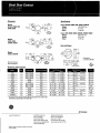
DSX-I048 Specifications
Size
DSX-1040E Cabinet
DSX-I040CDM
DSX-I042
15.5" W x 22.5" H x 6" 0
11" W x 4.5" H x 1.5" 0
11" W x 4.5" H x 1.5" 0
Weight
DSX-1040E Cabinet
DSX-I040CDM
DSX- 1042
DSX-1048 - Total
19.2 lb.
1.0 lb.
1.2 lb.
25.0 lb.
Finish
Black Powder Coat with White Silkscreen on Enclosure and Black
Enamel on DSX-1042.
Conduit Knockouts
1-1/4" to 2" concentric knockouts in Top, Bottom, Sides and Back of
enclosure.
@--
Output Voltage
Panel outputs provide a regulated, fused, DC voltage.
DSX-1042
12VDC
1A - Fused
DSX-I040CDM
12VDC
5 - 1.5A fused outputs
DSX-1040CDM
5VDC
3/8A fused
Outputs
Form C Relays
Relay Output Ratings
Open Collector Outputs
LED Outputs
Pre-Alarm Outputs
8
5 AMP 30 VDC 1 5 AMP 125 VAC
8 - negative 100ma
24 - 3 per reader port - negative 100ma
8 - 1 per door - negative 100ma
Access Controlled Entry Points
Card Reader or Keypad 8
Card and Reader Formats 140+
Any combination of card readers, keypads, or card and keypad
controlled entry points may be used.
Communication Ports
DSX-1042
RS-232 In
RS-232 Out
1040CDM
RS-232 [n
RS-232 Out
RS-485 In
RS-485 Out
Master to PC
Panel to DSX-I040CDM
Master to DSX-I040CDM
Slave Communications
From previous DSX-1048 Package
To subsequent DSX-l 048 Packages
Processor
AM186
20Mhz
RAMIROM Memory
Flash ROM
Standard RAM
512K
512K
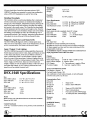
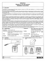
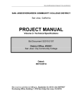
1048PKG Intelligent Controller Package
r---------------------------l
1040E (Enclosure)
:
DOOR CONTACT /INPUT 7
I
I MAGLOCK I OUTPUT 1 -----.
SLOT
1
SLOT
2
I
EXPANSION
SIDE A
READER,
INPUTS,
OUTPUTS
COMM IN
TRS-232/PC
SIDEA
READER,
INPUTS,
OUTPUTS
POWER IN
SIDES
READER,
INPUTS,
OUTPUTS
1042
SLAVE
A
READ\
'--'IT[ :
I
\
I I~
:
0
: S MAX DOOR PER l040E
I
2 DOORS PER 1042
I
I
I
I
I
I
I
I
~--------------------------~
B
I
COMM
EXIT REQUEST I INPUT S
,-i\,_
: Typical Door
B
A
COMM
SLOT
3
1042
MASTER
SIDES
READER,
INPUTS,
OUTPUTS
i
i
i
:
" I
1040PDP
POWER IN
1040PE (Enclosure)
SLOT
4
SIDE A
READER,
INPUTS,
OUTPUTS
1042
SLAVE
A
SLOT
5
S
I
COMM
SIDEA
READER,
INPUTS,
OUTPUTS
SIDES
READER,
INPUTS,
OUTPUTS
POWER IN
SIDES
READER,
INPUTS,
OUTPUTS
1042
SLAVE
A
B
I
COMM
POWER IN
TO
AS-150
l
AS-150
15V-8A
Ie e e e eel
1040CDM
SLOT
6
COMM
~
COMM
OUT
POWER
IN
~EXT
- . - TO
"POWER IN"
_
OF 1040CDM
POWER
OUT
r
FROM 1040PDM (SA)
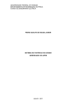
The DSX-1048PKG includes a DSX-1040E Enclosure, a DSX1040CDM Communication Distribution Module and 4 - lO42
Intelligent Controllers, This provides 8 Reader Ports, 32 Inputs,
and 16 Outputs, The DSX-I048 Package comes complete with 32lK ohm EOL Resistors, Lock & Key, Anchors and Wire Ties,
Tamper Switch, an External Power Indicator and a DSX-I040PDP
Power Distribution Panel.
The DSX-1040CDM receives RS-485 communications from a
possible previous panel and regenerates the 4 wire-RS485 to the
next DSX-1048PKG The DSX-I040CDM module also distributes
Slave Controller communication to the Slave panels within the
same enclosure. Each DSX-1042 is powered from an individually
CONTROLLER
POWER SOURCE
1
AS-100
I
I12V-8A I 24V-4A
1
Ie e e e e el
LOCK POWER
SOURCE
t-=TQ,-----l
AS-600R
AS-l00
' - - - - - - - - - - - ' - - - - - - . , 110VAC INPUT
~
~
.--------'-,
BATIERY(S)
FOR CONTROLLERS
(OPTIONAL)
BATIERY(S)
FOR LOCKS
fused 12 volt output from the DSX-l 040CDM Communications
Distribution Module. The DSX-I040CDM receives power from
the DSX-l 040PDP Power Distribution Panel.
Used in conjunction with the DSX-I048PKG is a DSX-1040PDP
or Power Distribution Panel. The DSX-I040PDP houses the panel
and lock power supplies, backup batteries, and fused power
distribution module. The DSX-I040PDP is comprised ofa DSX1040PE Enclosure, an AS-ISO 15V power supply for the Controllers, an AS-IOO-[12] or [24] for either 12V or 24V locks, and a
DSX-I040PDM. The DSX-I040PDM performs several critical
functions such as supervising Power Supplies and Batteries,
distributing power through fused outputs, and providing battery
charging circuits.
DSX Access Systems, Inc. 10731 Rockwall Road Dallas, Texas 75238
888-419-8353 Phone 214-553-6140 Phone 214-553-6147 Fax www.dsxinc.com
~
Powered from DSX Controller
~
Auto-sensing 10/100 Base-T / Auto-Duplexing
~.
RS-232 / RS485 Controller Communication
~
Configured through serial port
, . . Dial-Up Modem Backup - Optional
~
Built by DSX for DSX
~
Static or Dynamic Communications Server IP
~.
Simple to Configure w/ 3 entries
~.
Password Protected Programming
General Application
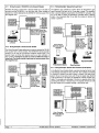
The DSX-LAN(M) module is typically used to connect a
Master Controller to the Host or Comm Server PC over a
Local or Wide Area Network. The WinDSX software is
inherently TCPIIP capable and can redirect communication,
that would nonnally be transmitted out a serial port, over a
LANIWAN to a particular IP address. The DSX-LANCM)
module receives that communication and converts it to RS232 or RS-485 that connects directly to the Master Controller. This adds another avenue offlexibility to WinDSX by
utilizing TCPIIP communications as well as dial-up modem
and direct serial port connectivity. All three means of communication can be used at the same time in the same system. The
DSX-LAN(M) is powered from the DSX Controller which
can provide battery backup.
The DSX-LAN(M) module is sold in two different configurations. The DSX-LAN which is the module with IP communications as the only method of connectivity. The DSXLAN(M) has dial up modem backup. The DSX-LAN module
must be ordered with the (M) option along with the DSX
modem to support the dial-up oackup feature.
Other Applications
The DSX-LAN can also be used at Slave Controllers with the
use ofthe PC Master Software. PC Master is a DSX software application that emulates a Master Controller. It gets its
download from the Comm Server PC and communicates with
all ofthe Slaves just like a Master Controller does. What is
different about the PC Master software is its ability to com-
municate with each Slave Controller via TCPIlP or with a
serial port connection. This allows Slave Controllers to be
placed on the LAN and each one or each group of controllers
to have a LAN connections using a LAN module. Modem
backup is not available for slave controller communication.
Dial-up Modem Backup
The DSX-LAN(M) module has a 9 pin serial port that is used
to connect a DSX modem for communications redundancy.
When the LAN(M) module detennines a loss ofnetwork
connectivity it switches to "Modem Mode" which allows the
controller to call the Comm Server or Host PC via the modem
when necessary. When the Network connection is re-established the Controller reconnects over the LAN. The modem
and the LAN(M) module are powered from the Controller
and are connected to each other via the supplied serial cable.
Call for availability ofthis feature
Power
The DSX-LAN(M) is powered from one ofthe Controllers
12VDC outputs requinng a mere 300ma. Powering the
module from the DSX Controller provides a good stable
battery backed up source.
Mounting
The DSX:LAN(M) is designed to fit in the same Equipment
Cabinet as the OSX-l 048 and DSX-l 022 Controllers. It can
mount on the inside or rest in the bottom ofthe enclosure. It
has three mounting holes and removable tenninal blocks.
DSXAccess Systems, Inc. 10731 Rockwall Road Dallas, Texas 75238 / 888-419-8353 /214-553-6140/ www.dsxinc.com
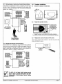
Location 1
Slave
Slave
Slave
Slave
Slave
Slave
Slave
Master
RS-485
"~
DSX-LANIMJ
Location 2
Slave
Slave
Slave
Slave
Slave
Slave
Slave
Master
Slave
Slave
Slave
with
Dial Backup
"~
. DSX-LANiMJ
1-------------------------------------------------
-----------,
I
:
:
:
I
I
Slave
Slave
Slave
Slave
:
:
:
Slave
I
:
RS-485"
I
I
I
I
I
I
I
I
~
DS}{-LANiMJ
I
I
I
I
I
I
I
I
Location 3
:
:
I
:
:
Slave
Slave
Slave
Slave
:
:
Slave
:
I
:
RS-485"
I
I
I
I
~
:
DSX-LANiMJ
I
I
I
I
~---------------------------------------------------------------~
Dialup Modem Backup is not available for Slave Communications
DSX-LAN(M) Specifications
Power Requirements
Size
DSX-LAN(M)
55"Wx3S'Hx 1.0"D
DC Input Voltage
12.0 oz.
RS-232 for Controller
RS-232 for Modem
RS-485 for Controller
10/100 Base-T
Communication Ports
Weight
DSX-LAN
12VDC@300ma
Finish
Black Powder Coat with White Silkscreen_
Temperature/Humidity
Warranty
Operating
Limited
0 to 70 C
1- 50 feet max
I-Optional
1 - 4000 feet max
1 - Autosensing
2 Year
DSX Access Systems, Inc. 10731 Rockwall Road Dallas, Texas 75238
888-419-8353 Phone 214-553-6140 Phone 214-553-6147 Fax www_dsxinc.com
LANCOM/0104.p65
The Indala 125 kHz Standard product line is part of HID's latest line of highly-secure proximity
readers. With a read range of up to five inches, Indala Standard Proximity readers are suitable
for a variety of applications. These high-quality Indala Proximity Readers deliver outstanding and
consistent performance with intelligent programming technology, uniform core modules, and a
range of stylish bezel designs including Curve, Arch, Linear, and Wave in a variety of colors. All
Indala Standard Proximity readers are available in three popular form factors: Classic, Mullion (Slim)
and Wallswitch for the ultimate choice.
Exclusive FlexSecu'-® Security Technology.
All HID Indala 125 kHz Proximity Readers feature FlexSecur technology, which provides an added
level of access system security through a verification process at the reader. A feature unique to the
HID Indala product line, FlexSecur screens out unauthorized cards prior to sending access control
data to the host system.
This additional verification step enhances the security of your access system in two ways:
I. The entire card data field is encrypted prior to programming the card. Therefore, the data on
the card cannot be decoded to determine the actual information on the card. Only the
reader is able to decrypt the data and transmit it to the access control system.
2. Cards and readers can be programmed uniquely for each site, protecting the end user against
unauthorized entry attempts by using cards from another facility. Again, this is unique to the
HID Indala product line.
Key Features:
Classic Reader
D Uniquely designed to replace a Wiegand Reader.
~ Dimensions are the same as the Classic Wiegand Swipe reader. Mounting holes match.
D Ideal for transitioning existing Wiegand users to proximity.
Mullion (Slim) Reader
& Can be mounted on any wall where limited space is an issue or where a slim, modern look is
preferred to a wallswitch-size reader.
D Ideal for mounting on door frames.
~
Suitable for indoor or outdoor use.
Wallswitch Reader
& The Wallswitch reader is similar in size to most U.S. switch plates.
I) Wallswitch reader can be mounted on a single gang box.
I) Suitable for indoor or outdoor use.
An ASSAABLOY Group brand
"
,.
0'·
Reader Fonn Factors
and Bezel Style Choices
',~~m~
"
,
Stylish readers are available in mullion-mount and
wallswitch in many attractive. "snap-on" bezel styles
and colors.
Indoor/Outdoor
Flexibility
All readers are fully potted and have weatherproof
electronics assemblies. making them suitable for
internal and external applications.
Easy Installation
Readers easily mount on a door mullion or single
gang electrical box.
Audio Tone
Programming Flexibility
Independently controllable audio tone can be tied to
LED function or separately controlled.
Classic
... ,
.
Compatible with Any Control Panel
Wiegand or Magnetic Stripe (Clock & Data) output easily interfaces with most existing
access-control panels,
Unbeatable Warranty and Technical Support
Customers can select HID Indala 125 kHz Proximity Readers with confidence because
HID offers a lifetime product warranty and global Technical Support.
Card Programming
The ProxSmith® Programmer System and Application Programming Interface puts flexibility and convenience in the hands of OEM and security professionals. With the ability
to quickly program a card or reader on site. users no longer need to rely on the factory
for custom formatted cards or readers. Plus. the ProxSmith Programmer System delivers the high level of security you expect from the HID Indala product line.
Mullion (Slim)
Wallswitch
Mounting
Dimensions
Power Supply
Current Requirements
Operating Temperature
Operating Humidity
Transmit Frequency
Environemntal
Certifications
Base Part Number
Color
Options
Warranty
Read Ranges**
FlexlSO" Card
FlexISO"XT
FlexCard"
FlexTag™
FlexKey'"
FlexlSO" MIFARE"
FlexlSO" DESFire TM
FlexlSO" iCLASS"
"'Package includes Core Electronics Module and bezel.
** Dependent upon installation conditions.
SpecificRtions are subject to change without notice.
© 2009 HID Global Corporation. All rights reserved. HID. the HID logo, Indala,
ProxSmith. FlexSecur and iCLASS are trademarks or registered trademarks of HID
Global in the U.S. andl or other countries. All other trademarks, service marks. and
product or service names are trademarks or registered trademarks of their respective
owners. Rev. 0512009
. MKT-STANDARD-DS-EN
Indala Prox
125 kHz Proximity - Credentials
t·:': -. \-:::.-~;-=::
iJ
FlexlSOilll
Base Part Number
Read Range:
*
Wallswitch Reader
Mullion (Slim) Reader
Mid-Range Reader
Long-Range Reader
Heavy-Duty PinProx
Keypad Reader
Membrane Keypad
Reader
Contact Smart Chip
Module Embeddable
Wiegand Strip
Magnetic Stripe
Visual Security Options
'=~
j~·.i .
.C~1 ..
FlexlSOilllXT
FlexlSOilll
DESFlre~
FlexlSQiIII
iCLASSiIII
FlexTag~
wwwGE,/nter/ogix,com
Steel Door Contact
all' and 1" contacts
1078/1076 Series
Overview
The GE Interlogix 1078 Series Steel Door contacts are designed
specifically for use in the steel doors commonly found in
commercial building applications, The unique housing design
features a rugged unibody construction with flexible ribbed sides
for quick, secure installation without gluing, The magnet housing
isolates the magnet from the surrounding steel for maximum gap
distances, both make and break, Over seven models including:
Wide Gap, SPOr, OPOr, and Biased for High Security applications
make the 1078 Series the most widely used and comprehensive
line available,
On available models a terminal connection (T) makes installation
easier. Simply strip the wire, insert it into the terminal block and
tighten. The terminal accepts any wire size from 14 to 22 gauge,
and has a unique one piece design for added strength
An optional Rare Earth Magnet is available, It is designed for use
inm~ta/:entry/exitgoors with a channel in the top of the door. The
,;,,:,:,~:::.t:~;~h~f£li~in~t~~'t~~:~~e,qtgCYU!rnounting hole in the door
. . ".;,":,. "., •,.,.:' .~'":. •:.,':., :. :.i.',.~~j~~:~;ji;.,/,·'··
.~~)~Jl~2l:\~~~;"(r:i:bl:~.~~{Jfeilid&§ihg~~Nj£~.:·~~~~ressed
:.;;:.,}""'" .:.' t:.1;:;~#::
Optional 1840
Rare Earth Magnet
:~~l;!~:;~~~;:~i:~~~e~::;:~;:;idthS'tQ~:~~f~;~;ie,:~y
. ·j~~:~~~!j!f~~:,~iim;/irjt{!;li~1:I[fJ~~.I~~;~.
·t·~~~),~;;~~~~»r~fi~(~1~'A~~fjj£~~t~~1tll£1;~~t,:'!'''::=:::::,:::::....
•,;;:i;;;;,:.'
1:
'\:,~f1eCifica.'iOn~ .• ,. p~/yKre:tijan~base9'qQrnPO~~d.fc,gntact'and~fg~et·bouSing:.~hall '.'.' ,,~ta~dard Features
"'ii·'
/'"
grey or mahogaiJY pr?'1n.· The m~giJetshall qe~f)de:otIj/IJIC():V.'
.
,I' . " " , ' ".
::~Al)~ ~~~it~··;~~;~~~~~tf~~I~!?1' ";:~dJi;:;:=:~7'=::::iI~
;~I'.
s;;
.,,~80th "'liit"&!~9OO'
PI"!f(:~ji;g;;~~~*i~f~~';~~7':~t:=.:
..
;~·
.::;
::::.
of
,''','; "~~' one piece thick-walled ABS plastic faY rT]aximilm s.trengtf1?~~;;;~~~ifels ~~~~~able
;':;;',:
amj"~~tJbility." ;.l~!Mi~;')''';'''··'' ".
0 Rare:Earth'iMagnet designed for steel door with top
','fjt'.~~~~~:r;"
.c~:\i~';.:(;: '"~"/
,,:.,,3?,:\~.:,(.1.
c·
-
channel ~':ailable
';.~.~ :
.~ ;,;"i.', :..~.
~~~'
.~tt~;>:~~
_
_
.,:
t
•
,:;
.,;.. Wk\',;·
:,Model numberS,.
1076, 1076W, 1076C, 1076CW, 10760, 1078, 1078W,
10mC, Jol.lier. (R)1078, 1078CTW
;;':;':Z;I:'\
Dimensions
Specifications
L
1.125'
1- 2.88
cm
Models:
(R)1078, 1078W, 1076,
1076W, 10760
~'563'
---l
3.97 cm 'I
T
0
100'
2.5ym
I ,I
Magnet
Part No. 1921
lincluded)
1.125
2.86 cm
L 1.125' --l
I' 2.86cm -I
Models:
1078C, 1076C,
1076CW, 1076CH
I - 1.563' ---l .375'
I'
3.97cm ' l i 2 ; -
~08=PT1.~~
J.¥j
Magnet
Part No. 1921C
lincluded)
2'22cm
.
Models:
1078Cr; 1076CTW,
_
1.625'
4.13 cm
--l
I - 1.56'
1
1
3.96 cm
~
~O&E
1
o
~
.. I
'I
(R) prefix indicates
Rare Earth Magnet
•
0.938'
2.36 em
I-
r
Fonn A: (R)1078, 1078W, 1078C, 1078er; 1078C1W
Voltage
100V AC/DC max.
Current
0.5 A max.
Power
7.5 W max.
Fonn C: 1076, 1076w, 10760, 1076C(O), 1076CW, 1076CH
Voltage
30V AC/DC max.
Current
0.25 A max.
Power
3.0 W max.
Rare faith Magnet
0.375'
0.64 em
j~
07~
J~m
Magnet
Part No. 1929
(included)
Protected by
U,S. Patent 5,844,458.
0.625'
FiJ-"~'i:C~=:...:.:::..cL1..59 cm
1.625' - - I
4.13cm
I
c@us
legs may
becutlor
Height Adjustment
USTED
Ordering Information
1076
1076W
10760
1078
1078W
1076C
1076CW
1078C
{R)1078
1078CT
1078CTW
1"
1"
1"
1"
1"
~
T
T
-1"%"
T
Electrical Config.
Open or Closed
Open or Closed
Open or Closed
Closed
Closed
Open or Closed
Open or Closed
Closed
Closed
Closed
Closed
SPOT
SPOT
OPOT
N/O
N/O
SPOT
SPOT
N/O
N/O
N/O
N/O
Hole Required
:
Contact
Magnet:
1" x 1.125"
1" x 1.125"
1" x 1.125"
1"x1.125"
1" x 1.125"
.75" x 1.125"
.75" x 1.125"
.75" x 1.125"
1" x 1.125"
.75" x 1.625"
.75" x 1.625"
1" x 1.563"
1" x 1.563"
1" x 1.563"
1" x 1.563"
1" x 1.563"
.75" x 1.563"
.75" x 1.563"
.75" x 1.563"
1" x 1.563"
.75" x 1.56"
.75" x 1.56"
Wood'
1"
2"
3/4"
1"
2"
7/8"
Gap Distance*
Steel'
Rare Earth
Up to l/Z"
Up to
%"
Up to 1"
Up to 3/8"
Up to l/Z"
Up to 5/8"
Up to 5/8"
Upto 1"
Up to 3ts"
Up to %"
2"
1/z"
N/A
1"
Up to l/Z"
7/8"
l/Z"
5/8"
Upto%"
N/A
* Gap distances are nominal make distance ±20%. Gap specifications are fur switch to make.
Break distance is approximately 1.1 to 1.5 times make.
•
www.GE-lnter/ogix.com.
©2002 GE Interlogix. All trademarks are properties 01 their owners.
C·3617-flGl0K-Il4IJ3
GE Interlogix
12345 SW Leveton Drive
Tualatin, OR 97062
Phone: 503-692-4052
USA & Canada: 800-547-2556
Technical Service: 800-648-7424
Faxback: 800-483-2495
2266 Second Street North
North St. Paul, MN 55109
Phone: 651-777-2690
USA & Canada: 800-777-5484
Technical Service: 800-777-2624
M,N,G
M,N,G
M,N,G
M,N,G
M, N,G
M, N,G
M,N
M,N,G
M,N
M,N
N
DS160/161
Request To Exit PIR sensors
Installation Instructions
1.0
Description
The OS160/161 is a passive-infrared (PIR) detector designed for request to exit (REX) interior applications. It is UL Listed as an access
control device under the UL 294 Standard.
The technology designed into the OS160/161 is based on the principal that all objects emit infrared energy. The warmer an object is, the more
infrared energy emitted. Its PIR technology allows the OS160/161 to detect the change in infrared energy that occurs when a person passes
through its field of view.
The OS160/161 has features such as Sequential LogiC Input (SLI) to eliminate unauthorized entry. SLI allows you to arm the detector using
any dry contact device, such as a second detector, card reader, or the access control system. This provides better control for this type of
application.
A built-in sounder can be automatically activated if the door is propped open. The sounder can be controlled from any dry contact device. The
OS160/161 detection pattern provides dense C-shaped coverage ideal for most REX applications. In addition, complete pattern control
allows it to be adjusted to a single zone or placed over a doorknob, for example. There are fifteen possible coverage patterns to accommodate most applications. This, combined with the ability to monitor the door and intelligently control the lock, adds considerable security to
these types of applications.
The OS160/161 uses Motion Analyzer II signal processing to help prevent false activation due to environmental conditions. The relay output
consists of two Form "C" contacts that can be adjusted to latch from approximately 0.5 to 64 seconds. The latch time features two modes of
operation, resettable (where the relay timer will not time out as long as someone is in the field of view) and non-resettable (where the relay
will remain latched for a fixed period of time). The relay can also be programmed to fail safe or fail secure in the event of power loss.
The OS160/161 may either be ceiling or wall mounted, and its pattern may be aimed and/or masked for more effective use based upon
installation needs. It is not designed as a primary means of exit for emergency egress applications.
The OS160/161 is available in a light grey (OS160) or a black (OS161) enclosure along with an optional trim plate (light gray TP160 or black
TP161) that can cover a single gang box. Panic hardware must be used with this or any other egress device.
2.0
Specifications
• Input Power:
• Temperature:
-20°F to +120°F (-29°X to +49°C). For UL
Listed installations, the temperature range
is +32°F to + 120°F (O°F to +49°C).
• Humidity:
0% to 95% non-condensing. 0% to 85%
non-condensing
for
UL
Listed
installations.
12 VOC to 30 VOC or AC
• Current Draw: 39 mA at 12 VAC, 76 mA at 30 VAC Alarm 39 mA at
12 VOC, 60 mA at 30 VOC Alarm 8 mA nominal
standby current
• Relay:
Two Form "C" contact sets rated for 1 A each at
30 VOC or AC max for resistive loads.
• Dimensions (xWxD):
1.8 in. x 7 in. x 1.75 in.
(4.5 cm x 17.8 cm x 4.4 cm)
• Sounder:
85 dB with adjustable volume
• Trim plate (HxW):
Optional. TP160 (light gray); TP161 (black)
3 in. x 8.25 in. (7.6 em x 21 cm)
3.0
Installation
3.1
Remove the cover using a small flat blade screwdriver.
)E
~
3.2
Rotate the detector clockwise to remove it from the
base.
3.3
Select a mounting location
.i" mDillD 0
~~::====ln=s=~=rt=~I=~=~=eW=d=r=iv~e~r
On the Ceiling
Secu rlt~fS~stems
BOSCH
~
Before you mount the unit, review Section 7 Coverage
Patterns for more information on the placement and
location of the OS1601161.
4.2
Contact Output Wiring
The normal settings of the contact outputs change depending on the
setting of the Relay Mode Switch (S3). See Section 5.3.
IMPORTANT
3.4
Route the wiring through the base before mounting the
base to the wall or ceiling. See Section 3.5when using the
optional trim plate (TP160 orTP161).
3.5
When using the optional trim plate (TP160 or TP161), run
the wiring through the trim plate and into the base before
mounting the base and trim plate onto a single gang
electrical box.
~
The arrows on the base indicate its correct mounting
orientation relative to the door.
IMPORTANT
3.6
DIP Switches
4.3
NCC NONCC NO
NCCNONCCNO
Motion Detected
Motion Detected
Wiring Examples
4.3.1 Basic Hookup
The basic hookup includes the DS160/161, a power supply, and a
magnetic lock. When the sensor sees motion, power is removed
from the magnetic lock.
Note the location of detector features.
Sounder
Fail Secure
(Switch 3 Off)
LED
NCCNONCCNO
-+RDTT
Control
Relay contacts shown with Switch 3 ON (Failsafe Mode) and Power On
4.0
Wiring
4.1
Power, Remote Input, Door Contacts, and Tamper
Many magnetic locks and electric door strikes have built-in spike
protection (also be called diode protected). If your lock is not spike
protected, install a bridge rectifier, such as a KBL005, between the
relay contacts and the magnetic lock/door strike as shown below.
(-). Connect to the negative side of the power supply.
(+) Connect to the positive side of the power
supply. The voltage must be between
12 VAC and 30 VAC or DC.
(R) Terminal R is for Sequential Logic Input
(SLI), the keycard input or for remote control
of the sounder. The contact must be
Normally Closed (NC). See Section 5.7 for
more information.
1m
ROTT
(D) Terminal D allows the detector to monitor
door contacts. See Sections 5.6 and 5.7
for more information. If used, these
contacts must be Normally Closed (NC) door contacts. Do Not
share these contacts with any alarm systems.
~
V1
Relay contacts shown with Switch 3 ON (Failsafe Mode) and Power
On.
(T) and (T) Normally Closed (NC) Tamper contacts.
IMPORTANT
.Page 2
4.3.2 Spike Protection
Before wiring the unit, review Wiring Examples in
Sections 4 and Sfor more information on the wiring
of the OS160/161.
~
Fa;'u", to sp.ke p.oteet the detecto. can shorten the
life of the relay contacts.
IMPORTANT
© 2004 Bosch Security Systems
DS160/161 Installation Instructions
5.0
Switch Settings
You can change the switch
settings by pressing the rocker
to the ON or OFF position.
5.5
111 DO
l§i
~c::::Ju.
~~
ON
5.1
LED Operation - Switch 1
Switch 1 ON - LED operates normally when motion is
detected.
Switch 1 OFF - LED is turned off.
5.2
Timer Reset Mode - Switch 2
Relay Mode - Switch 3
Switch 3 ON - The relays operate in the Fail Safe Mode.
See Section 4.2 Contact Output Wiring for the contact
information.
Relay Timer - Switches 4, 5, and 6
Setting Switches 4, 5, and 6 determines the amount of
time the output relays energize (between 0.5 sec and
64 sec) when motion is detected.
Use the following chart to set the relay timer.
Switch 7 ON - High sensitivity (REX Mode).
Switch 7 OFF - Low sensitivity (security sensor).
5.6
Door Secure Mode - Switches 8, 9, and 10
If the detector activates, but the door does not open, the
relay drops out after 10 sec. If the detector activates and the
door opens and then closes, the relay drops out after
2 sec. This prevents unauthorized people from entering.
Set the relay timer (see Section 5.4) for 16 sec or
longer for the Door Secure Mode to operate properly.
IMPORTANT
Switch 3 Off - The relays operate in the Fail Secure Mode.
The Fail Secure Mode must be authorized by your Local
Authority. See Section 4.2 Contact Output Wiring, for the
contact information.
5.4
The Signal Processing setting determines how sensitive
to movement the detector is.
llJ
Switch 2 ON - The relay timer starts when the detector
sees motion and restarts if there is additional motion. The
relay only drops out when there is no more motion and the
timer expires.
Switch 2 OFF - The relay timer starts when the detector
sees motion. It drops out when the timer runs out, even if
the motion continues. If the motion continues, the timer
restarts.
See Section 5.4 to select the time period.
5.3
OFF
Signal Processing - Switch 7
Switches 8, 9, and 10 ON - Door Secure Mode is enabled. Wire
according to Section 5.7.5 for door
secure.
Switches 8, 9, and 10 OFF - Door Secure Mode is disabled.
5.7
Remote Input Function - Switches 2,9, and 10
The Remote Input Function switches determine what the DS160/161
does when the contact attached to Terminal R is closed.
~
Keycard Input - An input to the Terminal R activates the
detector. Normally, this is used with a keycard reader outside
of the door/building. The internal sounder does not activate
when the keycard input is selected. The keycard inputs are ~B
affected by Resettable/Non-resettable Mode (Switch 2). The ic::::::::J-o
relay remains activated for as long as the keycard input is
closed. The timer starts when the keycard input is force ~
activated. If Switch 2 is on, toggling the keycard input again restarts
the timer ( the suggested setting). When Switch 2 is off, toggling the
keycard input does not restart the timer.
Direct Sounder Enabled - The sounder is turned on for long as the
contact on Terminal R is open. It does not affect the relay or timer.
Sequential Logic Input - The detector only activates if the Sequential
Logic Input (Terminal R) is open, or for 10 sec after it closes again.
Movement after 10 sec after the contact on Terminal R closes is
ignored.
Monitor Door Contacts - Door contacts connected to Terminal D
monitor if the door is open or closed. If the detector activates and the
door is open when 10 sec remain on the timer, the sounder turns on.
If the door opens without activating the detector, the sounder turns on.
The sounder remains on until the door closes or the detector activates.
For this feature to work, set the timer a minimum of 16 sec.
ic::::J-:
iiii:
Use the following chart to set the Remote Input function.
DS160/161 Installation Instructions
© 2004 Bosch Security Systems
Page 3
5.7.1 Wiring Example: DS160/161 and a Keycard Reader
5.7.3 Wiring Example: Sequential Logic Input
Normally, this setup is used when a keycard reader is on one side of
the door and the DS160/161 is on the other side. Either swiping a
keycard or a motion detected by the DS160/161 removes power from
the magnetic lock.
The detector only activates by motion when the Sequential Logic
Input (Terminal R) is open, or for 10 sec after it closes. For example,
when a second detector placed before the DS160/161 activates, and
for 10 sec after it resets, the DS160/161 activates when it detects
motion. Any movement after 10 sec after the contact on Terminal R
closes is ignored.
Relay contacts shown with
Switch 3 ON (Failsafe Mode)
Switches 9 & 10 are OFF
(Keycard Mode)
Relay contacts
shown with
Switch 3 ON
(Failsafe Mode)
Switch 9 is ON and
Switch 10 is OFF
(Monitor Extemal
Device Mode)
Keycard Reader
(Normally Open
contacts)
Input Devices
(Normally Closed
contacts)
5.7.2 Wiring Example: Direct Sounder Enable
The Direct Sounder Enable setting can be used to activate the DS160/
161 sounder from a remote contact. The DS160/161 internal sounder
remains on as long as the external contacts remain open. The
sounder input can come from devices such as a door controller or
door contacts. Turning the sounder on does not affect the relay or
relay timer. The direct sounder input does not remove power from
the magnetic lock.
B
PIRs
Keycard Readers
Photoelectric Beams
NCCNONCCNO
-+RDTT
Door Controller
(Normally Closed
contacts)
Relay contacts
shown with
Switch 3 ON
(Failsafe Mode)
Switch 9 is OFF
and Switch 10 is
ON (Direct
Sounder Mode)
In the Monitor Door Contacts Mode, a person entering the field of view
of the detector activates the relay and timer. Door contacts connected
to Terminal D monitor if the door is open or closed. If the relay timer
gets to 10 sec or less (only if set up for 16 sec or greater [see Section
5.4]) and the door is still open, the DS160/161 internal sounder activates. The sounder also activates if the door is opened without first
activating the detector or keycard input. The sounder remains on until
the door closes or by someone moving in the field of view.
Door Contacts
(Normally Closed
contacts)
Page
4
Floor Switches
5.7.4 Wiring Example: Monitor Door Contacts (First Option)
© 2004 Bosch Security Systems
Relay contacts
shown with
Switch 30N
(Failsafe Mode),
Switch 8 is OFF,
Switch 9 is ON and
Switch 10 is ON
(Monitor Door
'--_ _ _ _----' Contacts Mode)
DS160/161 Installation Instructions
5.7.5 Wiring Example: Monitor Door Contacts (Second Option)
6.0
Complete Insta"ation
If the detector is activated but the door is not opened, the relay drops
out after 10 sec. If the detector is activated and the door opens, then
closes, the relay drops out after 2 sec. This prevents unauthorized
people from entering.
r------,
6.1
Secure the detector inside base.
0
'LOll
,
1"
.
i
.
y
L
Relay contacts
shown with
Switch 3 ON
(Failsafe Mode)
Switch 8 is ON
(Door Secure
Mode)
..
"I,'
,1
",
'0;
.-'-.- .
D
+'
".' .' il
~
Rotate the barrel to the
desired location.
6.2
[
Secure by tightening the
lock-down screw.
Adjust the sounder volume.
To test the volume,
tum Switch 10 on
and apply power.
The sounder will turn
on as long as
Terminal R is open.
Door Contacts
(Normally Closed
contacts)
To adjust the volume, tum the Volume Control with a screwdriver.
Tum clockwise to increase the volume, and counterclockwise to decrease.
6.3
Floor Switches
or other inputs
Replace the cover and secure with screw.
Use a drill to remove screw knockout in the cover only, then start
screw and tighten to secure.
5.7.6 Disabling the Request-To-Exit (Example 1)
The 08160/161 can be disabled by using Terminal R and an external
device such as an access control or burglar alarm system. When the
contact connected to Terminal R closes, the 08160/161 disables
after a 10-sec delay. The 08160/161 returns to normal operation as
described in Section 5.7.3 after the contact closes.
Access Control
8ystem
Contacts
Self-Tapping
Screw
(provided)
Relay contacts
shown with
Switch 3 ON
(Failsafe Mode)
Switch 9 is ON and
Switch 10 is OFF
(Monitor External
Device Mode)
1
v~
The NFPA 101 Life Safely Code' ,""U,..S secu,,",
doors to have a "manual release device that shall
result in direct interruption of power to the lock independent of the access control system
IMPORTANT electronics".
08160/161 Installation Instructions
© 2004 Bosch 8ecurity 8ystems
Page 5
7.0
Coverage Patterns
7.2
The coverage (detection area) of the 081601161 varies depending
on the mounting height above the floor, angle of the lens, and if the
unit is mounted on a wall above the door or on the ceiling.
Masking
The 08160/161 is supplied with three masking wedges used to
disable any part of the coverage pattern. Each wedge covers
approximately 25% of the coverage pattern.
The unit can also be masked to allow only some parts of the coverage
pattern to be active.
7.1
Masking
wedge
Examples
When the unit is mounted on the wall and the lens is pointed straight
down, some detection zones point toward the wall and do not detect
movement.
Front View
.,
·I
-
.,
Views of coverage pattem with the unit mounted at 7.5 ft
(2.3 m) above the floor with the "eye" pointed straight down.
Zones that are polnted toward the wall are not shown.
w!':O:= :Or
!J
~.
.
,.i'
(~u~l1n ~~~i~t~:!!'r
Masking
wedge
Masking
wedge
Masking
wedge
Pattem on Floor
iN
['2]G'J
01:"3
'*65±%'
DElDDDO
000000
EJB
[3El
Insert a masking wedge by placing the bottom peg in first. Then
press on the center of the wedge until it snaps into place.
Side View
Select a section of the lens to mask
Insert the tab on the end of the wedge
in the hole in one side of the lens
~extured
I!/"f,
side
lacing out
Press here to snap
into place
2.5 ft.
(.7Sm)
The higher the unit is mounted, the larger the coverage area. 00 not
mount the 08160/161 more than 15 ft. (4.6 m) above the floor.
Side view 01 coverage pattem with the unit mounted at 15 It.
(4.6 m) above the floor with the "eye" pOinted straight down
Remove a wedge by placing the tip of a small screwdriver behind the
wedge and prying it up. 00 not scratch the lens when removing the
wedge.
Insert screwdriver behind wedge
Pry up to remove
5 It.
10ft.
(1.5m)
(3m)
Mounted on
wall above door
Mounted
on ceiling
When the 08160/161 is mounted on the wall above the door, you can
move the coverage pattern away from the wall by rotating the detector's
lens.
Page
6
© 2004 Bosch 8ecurity 8ystems
08160/161 Installation Instructions
Up to three masking wedges can be used if you only want to detect in
a very small area, such as around a doorknob or crash bar.
Masking
wedges
v~1The
cove,.ge pattem depends on how h;gh Ihe D81601
161 is mounted, location of the unit and the position of
the detector lens. If you want a setup as shown above,
mount the OS160/161 just above the door, on the hinge
IMPORTANT side, with the lens pointed down and slightly out.
OS160/161 Installation Instructions
© 2004 Bosch Security Systems
Page 7
AL400ULACM, AL400ULACMCB
Power Supply/Chargers w/Multi-Output
Access Power Controllers
Rev. DSAL400ULACM - A25F
Overview
• The AL400ULACM I AL400ULACMCB converts an 115VAC 60Hz input
into eight (8) independently controlled 12VDC or 24VDC Fail-Safe and/or
Fail-Secure outputs with a total of 4 amp @ 12VDC or 3 amp @ 24VDC
continuous supply current. Outputs are activated by an open collector sink or
normally open (NO) dry trigger input from an Access Control System, Card
Reader, Keypad, Push Button, PIR, etc. These units will route power to a
variety of access control hardware devices including Mag Locks, Electric
Strikes, Magnetic Door Holders, etc. The outputs will operate in both
Fail-Safe and/or Fail-Secure modes. The units are designed to be powered by
one common power source (factory installed) which will provide power for
both the board operation and locking devices, or two (2) totally independent
power sources, one (1) providing power for board operation and the other for
lock I accessory power. The FACP Interface enables Emergency Egress,
Alarm Monitoring, or may be used to trigger other auxiliary devices. The fire
alarm disconnect feature is individually selectable for any or all of the
eight (8) outputs.
AL400ULACM
AL400ULACMCB
• Eight (8) independently controlled
fuse protected outputs.
• Eight (8) independently controlled
PTC protected outputs.
Specifications
• 12VDC or 24VDC outputs.
• 12VDC @ 4 amp supply current
or 24VDC @ 3 amp supply current.
• Class 2 Rated power limited outputs.
• Power supply input options:
a) One (1) common power input for ACM81
ACM8CB and lock power (factory installed).
b) Two (2) isolated power inputs - One (1) to power
the ACM8/ACM8CB and one (1) for lock
accessory power, (external power supply
is required). (Current is determined by the
power supply connected, not to exceed a
maximum of 10 amp total).
• Eight (8) Access Control System trigger inputs.
Input options:
a) Eight (8) normally open (NO) inputs.
b) Eight (8) open collector inputs.
c) Any combination of the above.
• Eight (8) independently controlled outputs.
Output options:
a) Eight (8) Fail-Safe and/or Fail-Secure power outputs.
b) Eight (8) form "C" 5 amp rated relay outputs
(AL400ULACM only).
c) Any combination of the above (AL400ULACM only).
• Eight (8) auxiliary power outputs (unswitched)
• Output ratings:
- Fuses are rated @ 3.5 amp (AL400ULACM).
- PTCs are rated @ 2.5 amp (AL400ULACMCB).
• ACM8 board main fuse is rated at 10 amp.
• Input 115VAC 60Hz rated @ 1.9 amp.
• Filtered and electronically regulated outputs
(built-in power supply).
• Red LEDs indicate outputs are triggered (relays energized).
• Fire Alarm disconnect (latching or non-latching) is
individually selectable for any or all of the
eight (8) outputs.
Fire Alarm disconnect input options:
a) Normally open (NO) or normally closed (NC)
dry contact input.
b) Polarity reversal input from FACP
signaling circuit.
• Alarm output relay indicates that FACP input
is triggered (form "C" contact rated @ 1 amp 28VDC
not evaluated by UL).
• Green LED indicates when FACP disconnect
is triggered.
• Built-in charger for sealed lead acid or gel type batteries.
• AL400ULXB (Power Supply Board)
maximum charge current. 7 amp.
• Automatic switch over to stand-by battery
when AC fails.
• AC input and DC output LED indicators.
• Zero voltage drop when unit switches over to battery
backup (AC failure condition).
• Short circuit and thermal overload protection.
• AC fail supervision (form "C" contact).
• Battery fail and battery presence supervision
(form "C" contact).
• Enclosure accommodates up to two (2) 12AH batteries.
• Product weight:
- AL400ULACM: 11.1 lbs.
- AL400ULACMCB:1O.1Ibs.
• Shipping weight:
- AL400ULACM: 9.8Ibs.
- AL400ULACMCB: 11.4 lbs.
Agencv Approvals
.
L0 UL
Listed for Access Control Systems Units
(UL 294).
~"
MEA
Approved
CUL Listed - CSA Standard C22.2
No.20S-M1983 Signal Equipment.
MEA - NYC Department of
Buildings Approved.
CSFM - California State Fire
Marshal Approved.
Enclosure Dimensions
lS.S"H x 12"W x 4.S"D
..
,
..r
.875'
_1.22"--
~.
"
/.
lJ.2!l"
",
53'
r--< 7-
r
l~T
rt ~
f? ~
~IJI
.n'
~2.25
~
as,
rt ~
~
IJI
IJI
4.56"
\ltl'onh Curp. - 14115Sth Slrl'l't. B,rnokhll. N' 1112(1- 7IS-507-SIXI· SSS-25S-766<)· altrunh.l'HIll
!
"
"
Maxim70
AccessPowerConuoHer
Rev. DSMAXIM7D - H 13J
OvelYiew
This unit distributes and switches power to access control systems and
accessories. Unit converts a 115VAC 60Hz input into sixteen (16) independently
controlled 24VDC Class 2 Rated PTC protected power-limited outputs. The outputs
are activated by an open collector sink or normally open (NO) dry trigger input from
an Access Control System, Keypad, Push Button, REX PIR, etc. Units will route
power to a variety of access control hardware devices including: Mag Locks, Electric
Strikes, Magnetic Door Holders, etc; Outputs will operate in both Fail-Safe and/or
Fail-Secure modes. The FACP Interface enables Emergency Egress, Alarm Monitoring, or may be used to trigger other auxiliary devices. The fire alarm disconnect
feature is individually selectable for any or all of the sixteen (16) outputs. All interconnecting equipment must be UL Listed.
Specifications
•
•
•
•
•
•
•
•
•
•
•
•
24VDC outputs.
Maximum output current: 24VDC @ 9.4 amp.
Class 2 Rated power limited outputs.
115VAC 60Hz, 6.5 amp input.
Input fuse rated @ 10 amp/250V.
Power supply input options:
a) Two (2) common power input for either ACM8CB
and lock power (factory installed).
b) Two (2) isolated power inputs (external power
supply is required), (current is determined by the
power supply connected, not to exceed a
maximum of 10 amp total).
Sixteen (16) Access Control System trigger inputs.
Input options:
a) Sixteen (16) normally open (NO) inputs.
b) Sixteen (16) open collector inputs.
c) Any combination of the above.
Sixteen (16) independently controlled outputs can be
Fail-Safe and/or Fail-Secure power outputs.
Sixteen (16) auxiliary power outputs (unswitched)
(outputs are rated @ 2 amp).
ACM8CB boards main fuse is rated at 10 amp.
Output PTC are rated @ 2.5 amp.
Red LEDs indicate outputs are triggered
(relays energized).
Fire Alarm disconnect (latching or non-latching) is
individually selectable for any or all of the
sixteen (16) outputs.
• Fire Alarm disconnect input options:
a) Normally open (NO) or normally closed (NC) dry
contact input.
b) Polarity reversal input from FACP signaling circuit.
• Alarm output relay indicates that FACP input is
triggered (form "c" contact rated @ 1 amp 28VDC).
• Green LED indicates FACP disconnect is triggered.
• Filtered and electronically regulated outputs
(built-inpower supply board(s».
• Built-in charger for sealed lead acid or gel type
batteries.
• Maximum charge current 3.6 amp.
• Automatic switch over to stand-by battery when
AC fails.
• Zero voltage drop when unit switches over to battery
backup (AC failure condition).
• Thermal and short circuit protection with auto reset.
• AC input and DC output LED indicators.
• AC fail supervision (form "c" contact).
• Low battery and battery presence supervision
(form "c" contact).
• Enclosure accommodates up to four (4)
12AH batteries.
• Product weight: 39.0 lbs.
• Shipping weight: 43.0 lbs.
Agencv Approvals
®
Iii:\ CUL Listed - CSA Standard C22.2
UL Listed for Access Control System Units
(IlL 294).
~
No.205-M1983, Signal Equipment
CSFM
California State Fire Marshal Approved.
Enclosure Dimensions (approximatel
26"H x 19"W x 6.2S"D
14.5"
4.5"
f----4.5"----j
4.0"
6.5"
1.5"
1.25"-
1.5"
1.1.
:\0"
'''-
-f{--Hf}------f-1.5"
-f+-+-lft-----f-4.0"
18"
18"
18"
10"
*+-J+------+l0.0"
1l
l'r
1 - - - - 4.5"----1
)
p=
D:1
1
='1.5~
1.
r
4.5"
4.5"
.l
If ~
~ l}'
If ~
If ~
7.25"
2.75"
~ bJI
~ l}'
1"j
2.75"
14.5"
•
\11 !"lIlIlX LUI p. - l-tll ::iXt h Sit "l'l. ~I lIol,h'lI. !\ \' 112211 • 71 H~~(,7-X I XI· XXX-l':;X-7M)l) •. lIt rUIlh:
I
((Jill
•
I
.
"
•
Universal SLA-VRLA Batteries UB-1270 (40800)
Group Type: UB -12 V SLA 0.8 to 10Ah Weight: 6 Lbs
Voltage: 12 V
AH: 7 AH
Terminal: F1
BCI:
Length: 6
Width: 2.6
Height: 3.7
PRODUCT DATA SHEET
Controlled Document - Engineering Drive
1530 Shields Drive
Waukegan,IL 60085
Toll-Free (800) 323-9355
Fax: (847) 689-1192
PART NUMBER:
DESCRIPTION:
CONSTRUCTION:
APPROVALS:
APPLICATION:
71702
1612 STRANDED CMP/CL3P FT6 PLENUM CABLE
This cable consists of two bare copper insulated conductors and an overall jacket.
UL Standard 13, 444; NEC Articles 725 & 800.
Communications Cable, Class 3 Power Limited Circuit Cable used for Plenum Applications.
Construction Parameters:
Conductor
Stranding
Insulation Material
Insulation Thickness
Insulated Conductor Diameter
Number of Conductors
Lay Length
Jacket Material
Jacket Thickness
Overall Cable Diameter
Approximate Cable Weight
Flame Rating
16 AWG Bare Copper
19/.0117"
Low Smoke PVC
0.006" Nom.
0.070" Nom.
2
5.00" Nom.
Low Smoke PVC
0.014" Nom.
0.168" Nom.
25.6 Lbsl1 M' Nom.
NFPA 262 Steiner Tunnel Smoke and Flame Test
Electrical Properties:
Temperature Rating
Operating Voltage
Capacitance Between Conductors @ 1 KHz
Capacitance Between Conductors to Shield @ 1 KHz
DC Resistance per Conductor @ 20°C
-20°C to 75°C
300V Max per NEC Article 800
45 pF/ft Nom.
Insulation Colors
Jacket Color
Black Red
Beige
Legend (Surface Ink Print)
COLEMAN CABLE 71702 16 AWG 21C C(ETL) US (ETL CODE) TYPE CMP/CL3P 75C
TYPECMP FT6
3.92 Ohmsl1M' Nom.
This product complies w~h European Directive 2002/95/EC (RoHS)
On special orders, the customer will accept all factory lengths and +/-10 percent of total order nequested.
Cable has a rip cord for easy jacket nemoval. The jacket is sequentially footmarked.
The information pnesented here is, to the best of our knowledge, true and accurate. Since conditions of use ane beyond Coleman Cable's
control all product data presented is for informational purposes onty and does not create a binding obligation or liability on Coleman Cable
or confer any rights on any customer. The sale of products(s) is conditioned upon acceptance of
apurchase order subject to Coleman
Cable's standard terms and conditions contained thenein, induding without limitation Coleman Cable's standard warranty. Coleman Cable
disdaims all liability in connection wilh the use of information contained herein or otherwise.
This specification is proprietary intellectual property of Coleman Cable. Any information contained henein shall not be disdosed to any
party without written consent of Coleman Cable.
Customer Name._ _ _ _ _ _ _ _ _ _ _ _ _ _ _ _ Date Signed _ _ _ _ _ _ _ __
Customer Approval _ _ _ _ _ _ _ _ _ _ _ _ _ _ _ __
Specification Issue Date: April 19, 2006
1-OOQ..323-9355 (Phone)
1-847-689-1192 (Fax)
Designed By: PEM
71702
@ 2006 Coleman Cable, Inc.
PRODUCT DATA SHEET
Controlled Document - Engineering Drive
1530 Shields Drive
Waukegan, IL 60085
Toll-Free (800) 323-9355
Fax: (847) 689-1192
PART NUMBER:
DESCRIPTION:
CONSTRUCTION:
APPROVALS:
APPLICATION:
72304
2214 STRANDED CL3P/CMP FT6 PLENUM CABLE
This cable consists of four bare copper insulated conductors and an overall jacket.
UL Standard 13 and 444, NEC Articles 725 and 800.
Class 3 Power Limited Circuit Cable and Communications Cable Used in Plenum Applications
Construction Parameters:
Conductor
Stranding
Insulation Material
Insulation Thickness
Insulated Conductor Diameter
Number of Conductors
Lay Length
Jacket Material
Jacket Thickness
Overall Cable Diameter
Approximate Cable Weight
Flame Rating
22 AWG Bare Copper
7/30
Low Smoke PVC
0.006" Nom.
0.041" Nom.
4
Parallel
Low Smoke PVC
0.014" Nom.
0.127" Nom.
15.8 Lbsl1M' Nom.
NFPA 262 Steiner Tunnel Smoke and Flame Test
Electrical Properties:
Temperature Rating
Operating Voltage
Capacitance Between Conductors @ 1 KHz
Capacitance Between Conductors to Shield @ 1 KHz
DC Resistance per Conductor @ 20°C
-20°C to 75°C
300V Max per NEG Article 800
31 pFIft Nom.
Insulation Colors
Jacket Color
Black Red White Green
Beige
Legend (Surface Ink Print)
COLEMAN CABLE 72304 22 AWG 4/C C(ETL) US (ETL CODE) TYPE CMP/CL3P 75C
- TYPE CMP FT6
16.19 Ohms/1 M' Nom.
This product complies with European Directive 2002l95IEC (RoHS)
On special orders, the customer will accepl all factory lengths and +/- 10 percent of total order requested.
Cable has a rip cord for easy jacket removal. The jacket is sequentially footmarked.
The information presented here is, to the best of our knowledge, true and accurate. Since conditions of use are beyond Coleman Cable's
control all product data presented is for informational purposes only and does not create a binding obligation or liabilily on Coleman Cable
or confer any rights on any customer. The sale of products(s) is conditioned upon acceptance of a purchase order subject to Coleman
Cable's standard terms and conditions contained therein, including without limitation Coleman Cable's standard warranly. Coleman Cable
disclaims aliliabilily in connection with the use of information contained herein or otherwise.
This specification is proprietary intellectual properly of Coleman Cable. Any information contained herein shall not be disclosed to any
parly without written consent of Coleman Cable.
Customer Name_ _ _ _ _ _ _ _ _ _ _ _ _ _ _ _ Date Signed _ _ _ _ _ _ _ __
Customer Approval _ _ _ _ _ _ _ _ _ _ _ _ _ _ __
Specification Issue Date: July 19, 2006
1-800-323-9355 (Phone)
(Fax)
1-847~9-1192
72304
Designed By: PEP
@2006 Coleman Cable, Inc.
PRODUCT DATA SHEET
Controlled Document - Engineering Drive
1530 Shields Drive
Waukegan, IL 60085
Toll-Free (800) 323-9355
Fax: (847) 689-1192
PART NUMBER:
DESCRIPTION:
CONSTRUCTION:
APPROVALS:
75906
18/6 STRANDED SHIELDED CL3P/CMP/FPLP FT6 PLENUM CABLE
This cable consists of six bare copper insulated conductors, cabled with an overall shield
and drain wire, and an overall jacket.
UL Standard 13 and 444, NEC Articles 725 and 800.
Power Limited Circuit Cable And Communications Cable Used in Plenum Applications
Construction Parameters:
Conductor
Stranding
Insulation Material
Insulation Thickness
Insulated Conductor Diameter
Number of Conductors
Lay Leng1h
Shield
Drain
Jacket Material
Jacket Thickness
Overall Cable Diameter
Approximate Cable Weight
Flame Rating
Cable Cross-Section
18 AWG Bare Copper
71.0152"
Low Smoke PVC
0.010" Nom.
0.066" Nom.
6
5.00" Nom.
AlumlMylar
24 AWG 7/24 Tinned Copper
Low Smoke PVC
0.017" Nom.
0.232" Nom.
51.4 LbS/1M' Nom.
NFPA 262 Steiner Tunnel Smoke and Flame Test
Electrical & Enviromental Properties:
Temperature Rating
Operating Voltage
Capacitance Between Conductors @ 1 KHz
Capacitance Between Conductors to Shield @ 1 KHz
DC Resistance per Conductor @ 20°C
-20°C to 75°C
300 V RMS Max.
50 pFlI! Nom.
92 pFIft Nom.
6.29 Ohms/1M' Nom.
Insulation Colors
Jacket Color
Black Red White Green Brown Blue
Beige (Other colors available for minimum order)
Legend (Surface Ink Print)
COLEMAN CABLE 75906 18 AWG 6/C C(ETL) US (ETL CODE) TYPE CMP/CL3P/FPLP
75C - TYPE CMP FT6
This product complies with European Directive 2002l95/EC (RoHS)
On special orders, the customer will accept all factory lengths and +/- 10 percent of total order requested.
Cable has a rip cord for easy jacket removal. The jacket is sequentially footmar1<ed.
The infonnation presented here is, to the best of our knowledge, true and accurate. Since conditions of use are beyond Coleman Cable's
control all product data presented is for informational purposes only and does not create a binding obligation or liabilily on Coleman Cable
or confer any rights on any rustomer. The sale of products(s) is conditioned upon aoceptance of a purchase order subject to Coleman
Cable's standard tenns and conditions contained therein, including without limitation Coleman Cable's standard wanranly. Coleman Cable
disclaims aliliabilily in connection with the use of information contained herein or otherwise.
This specification is proprietary intellectual property of Coleman Cable. Any infonnation contained herein shall not be disclosed to any
party without written consent of Coleman Cable.
Customer Name--,_ _ _ _ _ _ _ _ _ _ _ _ _ _ _ Date Signed _ _ _ _ _ _ __
Customer Approval _ _ _ _ _ _ _ _ _ _ _ _ _ _ _ __
Specification Issue Date: July 19, 2006
1-800-323-9355 (Phone)
1-847-089-1192 (Fax)
Designed By: PEP
75906
@ 2006 Coleman Cable, Inc.
TOSHIBA
Leading Innovation
NVS/I PS Series
:J»>
Network Video Recorders
Advanced Network Based Digital Recording
":,:'
::'.'
•
Record up to 32 network-based cameras.
•
Records IP based cameras both locally and globally
via the Internet.
•
Recorded image resolutions as high as the network
camera supports .
•
Complete remote access, setup control, user administration,
video backup, live viewing, and powerful search capabilities.
".
.~"$oJ~~
-~~~.
'.
"
.
.
II
Megapixel camera support for super high resolution images.
•
Dual monitor support on all systems.
II
Support for majOr network video device manufacturers
including Toshiba, Sony, Panasonic, AXIS, Lumenera, ACTi,
Arecont Vision, and Vantage.*
,'.,'-,
~Detailed
list at 'v\'\t\IVI.toshibasecurity.com
NVS Series
IPS Series
Network Video Recorders
Network Video Recorders
With available Internal RAID 5 HOD capabilities and field-replaceable hard
disk drives, the NVS series is designed to support network-based cameras.
Capable of recording at super high resolutions and at speeds of up to 30
PPS per camera, the NVS offers unmatched versatility.
Designed to support both video encoders and network cameras, the IPS
is a robust network based video surveillance solution in a streamlined
3U chassis. Capable of recording at megapixel resolutions and up to 30
PPS per camera, cameras can be connected both locally or from remote
locations over the Intemet.
Recording Resolutions
. Recording resolutions dependent on the
supported resolutions of the network cameras
IP Video Input
Upto 32 Ch.
Recording Resolutions
Recording resolutions dependent on the
supported resolutions of the network cameras
IP Video Input
Upt032Ch.
DVI-Dx 1, SVGAx l '
Video Output
DVI-D x 1, SVGAx 1
Video Output
Recording Rate
Up to 30 PPS Per Camera'
Recording Rate
Up to 30 PPS Per Camera"
Audio Recording
Up to 16 CH (on suppaned net'MOr1< caCOOrRS)
PTZ Controls
Via IP Protocols
PTZ Controls
Via IP Protocols
Storage Capacity
Up to 4 Terabytes
Image Compression
Proprietary MJPEG, MPEG4, H.264
LAN
100/1000 Gigabit Ethernet
Storage Capacity
Up to 8 Terabytes
Critical Recording Archive
DVID Multi Burner, Network, USB
LAN
100/1000 Gigabit Ethernet
Password Control
User Defined Access Level
Critical Recording Archive
DVID
Power Interruption Recovery
Automatic restart after power interuption!
recording operation resumes
Mu~i
Burner, Network, USB
Password Control
User Defined Access Level
Power Interruption Recovery
Automatic restart after power interuption!
recording operation resumes
TCP~P, UDP, Internet, LAN. WAN
............................... ..................................................
.
Remote Connection
;
UDp, Internet. LAN. WAN
Remote Connection
TCP~R
Power Input
AC 100-240V Input (50 Hz/50 Hz)
Power Input
AC 100-240V Input (50 Hz/50 Hz)
Central Processing Unit
Intel® Core TM2 Quad 2 Ghz+
RAM
2 GB (8/16 CH ~IS), 3 GB (32 CH models)
Central Processing Unit
Intel® Core TM2 Quad 2 Ghz+
Operating System
Microsoft® Windows® XP Embedded
RAM
2 GB (8/16 CH models), 3 GB (32 CH model~)
Dimensions (h x w x d)
5.8" x 17.25" x 19.5" (14Bmm x 438mm X 495rrm)
Operating System
Microsoft® Windows® XP Embedded
Weight
Dimensions (h x w x d)
7" x 17.3" x 21.75"
30-33 Ibs (13.6-15 kg)
40-43 Ibs (18-195 kg) w~h packaging
Weight
47-52 Ibs (21.3-23.5 kg)
64 - 84 Ibs (29·38 kg) with packaging
(18Omm
x MOmm x 552mm)
• Monitor not included. Monitor is required for setup and maintenance.
U
Total recording throughput dependent on multiple factors including: system specs, camera eodee,
camera settings, camera resolution, and network bandwidth. Refer to the Toshiba IF platform
estimator for mOl'e inforrnation on tt18 specifics of your installation.
Specifications subject to change without notice
NVS SERIES PART NUMBERS
SAMPLE NVS/IPS CONFIGURATION
NVS32-1T12T13T14T16T18T
NVS1 6-1T/2T13T/4T16T18T
NVS8-500G/1T/2T/3T/4T/6T/8T
OPTIONAL ACCESSORIES FOR NVS
• Internal RAID5 (DVR-R5)
• Additional Hard Drives (1TB: HDD-1T8, 2T8: HDD-2TB)
• Redundant Power Supply (2-RDNT-PS)
• 16CH Audio Card (16-AUD)
• Extended Warranties (EW-S3Y/S4Y/S5y)
For more inforrnation, contact your sales representative.
IPS SERIES PART NUMBERS
IPS32-500G/1T/2T/4T
IPS16-500G/1T/2T/4T
IPS8-500G/1 T12T14T
SCSManagemenlStalIO'1
OPTIONAL ACCESSORIES FOR IPS
• Extended Warranties (EW-S3Y/S4Y/S5y)
• SCS-OPT SCS Connectivity Upgrade
For more information, contact your sales representative.
c@us
02009 Toohba AA"erl;a Inb:maton Systems, In::. NI oghts reserve:I. II! pn::ducIs a'"d nanos rrer::x::n3d
are lr-e property r:J It'elr resP'lClM'l owners. wtlile Toshtba has maoe f:NfSY effort fit Ire nme of po.dcat01
to ensure ttle !ICC.racy :1 th(llntO'lna~OI1 (fOVded "ernn, p'oduc~ speclfJ:allorls, c:rrg.rnllons pn:es
~oomOQ('lMtS.anloOllans1l'ladat)~tyarealsu/:ljeC\lOcnangeW\lto.Jlrw:JllCe.
29499AA Rev1
Toshiba America Information Systems, Inc.
Surveillance & IP Video Products, Imaging System Division
9740 Irvine Boulevard, Irvine, Califomia 92618
(877) 855-1349 • www.toshibasecurity.com
TOSHIBA
Leading Innovation
»>
Leading Innovation
IK-WR12A
»>
IP NETWORK MEGAPIXEL DOME WITH
EXTREME LOW LIGHT CAPABILITIES
• IP66 rated weatherproof for outdoor with'
built-in heater/blower (-22 0 F to 122 0 F)
I
• IR LEDs .provide 0,0 lux min, illuminatior)
1
'I
• IR LEDs enables video capture in total
darkness for true 24/7 surveillance
I
• Vandal-resistant housing protects camera
against tampering and damage
'j
• 2MP resolution (1600 x 1200)
I
• VarHocal 3-9 mm with 4x digital zoom
j
• Quad streaming MPEG4 and Motion JPEG
!
• Two-way audio
I
• Power over Ethernet, 12V DC or 24V AC
• Day/night imaging
_~
.
1
':'~~~--=-~:---~_=_ ~.=:'::
.~---<::
--:~~·'~"-·-·-",··-·--:l
.,
..::,,:::'::-• SD/SDHG cara.s,lot:fofI0catreGording:::::-_-=~,=.~:·~-:'-·-'
:::- ~
•
~-c:'~-~::;:-~c:,,-~,:_c:-.:..._.: :_.__
~ : : : :~=~= =: .;. : :.:.c,~.:=,·
:_:_:::::,_7C
"':7"'::>
__ ~_)~'
_ ' ......
""~""""'.u,..,
_'-.',..,
IK-WR12A
IP NETWORK MEGAPIXEL DOME
IMAGING
!~~g.~ ..~~~~9.~....................................................................!!?!.:~.:!~~~ .. .9.~.Q$ ..
~!f~!i~~.. f.\c.!l!.~~..~!~.~~D.t. ........................................................~.~Q.9..x.... ~.?Q.9. ..
§~.~~f.1.i~g..~y.?!~.~......................................................................... er.~g.~~§§.i~.E? ..
Lens
Vari-Focal f=3mm to 9mm
....................................................................................................................................
~f.1g!~ ..~f.y.i.E?~.................................................t!: ..~Q.~..!9.. ~T.!.Y: ..~?~..!9.. ~.~~ ..
f.~~.y.~.§y.?!~.~.........................................................................................~.~~l!.~!..
!~~g.~ ..q~~P.!.~~§!9.~ ..~~.~.~!......................~p.~~! ..~.p.~Q~.(~~~! ..c.9.~~.<?1 ..
Minimum illumination
0.0 luxlF1.2 with IR LED on
....................................................................................................................................
White Balance
AWB
....................................................................................................................................
Gain AGC
Auto
....................................................................................................................................
BLC
Yes
....................................................................................................................................
f.1!~.~~~.E??~......................................................... .Y~.i?.'.. ~.Q!:!y.~.9.t!~ ..i?.E?.!~~~~~.I.E?. ..
P.r.i~.~c.y...~9.?~ .................................................................................................X!?? ..
!.~~p.~!..Q~.~~~.~~~f.1.........................................................................................XE?? ..
Motion Detection
Yes
....................................................................................................................................
ePTZ
Yes
....................................................................................................................................
~~9.~................................................................................~0..9.p.~.i.~!! ..~~..~!g.i~~! ..
Q9.y!f.1.i.g~~ ...................................................................f3.~~~~.~q!~.. !R~.c.~~..~!~~!. ..
. ENVIRONMENT
IP Code
IP66
....................................................................................................................................
!:!.~~!~~I.~~.t:l.. (B.19.~~r) ..............................................................................!?~!!!..i.~ ..
!.E?~p.~!:~!l!.~~.E~ng.E? ..........................:?.~~.F..~.~ ..~.??~.. F... (~.~Q.~..g.~.~U?Q.~ ..q ..
NE1WORKING
Support-protocol
TCP/ IP, HTIP, HTTPs, UPnP, SNMP
RTSP/RTP/RTCP, IGMP, SMTp, FTp,
.................................................................Q.Ij.9.e ..~m:~. p.~$!.pp.~.~.'.. p.p.p~~ ..
!f.1.~~!:~~.~.F?~9.~~.C.~! ...............................................................................I.~.~! ..I.~~ ..
9.9.~.E?~~..~.~!.y.p...P..~~.g~~.~................................. !f.1.?~~!!~~ig~..Y.Y.!~~!:~.A~~!~~0. ..
MP.~.G.~/~p.~.~ ............................................ .$.!f.I:l.~!!9.~~.~~§..f9.y.r..?!r.E?~~!~g.? ..
!?9~g..~!g.~~..c.9~!!.~! ....................................................................... 99.~!....G.~$ ..
Image Sizes
1600x1200, 1280x960, 800x600,
........................................................................~Qx...~~.Q! ..~?Q~?~9.'.. .1.!.~.x...!.¥ ..
Frames per second (fps)
SVGA: 30 fps (MPEG, JPEG)
..........................................................~.~9A.:.. ~.t?~p.~..(~e~Q)!.. ~.t?..fp.~..(~P~91 ..
The IK-WR12A is weatherproof and vandal-resistant. It has an IP66 rating, meaning that its electronics are protected against dust, water/moisture/humidity, and impact. It will also detect tampering by blockage or
spray paint. Install it with confidence in high-risk schools, jails, retail,
parking lots, warehouses, airports, or anywhere outdoors. The advanced
codec technology allows you to easily view, control, and manage all networked cameras using a standard web browser or Toshiba's surveillance management software from any networked computer.
MECHANICAL
Q!~~~?igf.1.? ..........................................................................~:.?:'.. (~).~..t?:.~:'..(t!)..
!B..I.I!l!.~.if.1.~!g~§.......................................................~ff~.c.!!~~.. l!p..~~..?Q..f.I:l.~!~~~..
!:!.y.~.i.~!!Y..gf.gF?~r.~~!9~ ....................................................................~9. .t.~.~.Q%. ..
~~.i.g~~................................................................................ ~:~.~.. !.~q.i?(?.'.}.~~..g)..
p.9.~~r..R~q~!r.E?f.I:l.E?~~? ..................... Q9...~.?.Y.*-.1.Q.%!..~g .?~Y.~}9.%.'.. P.9.~..
P.9.~~!:.9.9.~§.':l.~p.!!9.~.............................. !.:.~~..(~?Y.g.9L~.~:A~..(?~Y~9.L
B9..Ij.~...................................................................................................~~p.!!~~!..
Standards
FCC/A and B, IC (lCES-003),
Multi levellDlPassword, IP address
filtering, HTTPS, 802.1x port-based
authentication
....................................................................................................................................
.......................................................................................y~~.Q~.t?Q.'.. 9.§~.9..?~:.~..
QQ.r:-!.~......................................................................t:lg.:!p.:g().~ ..c.~9.~g.E?!p.:~.~~ ..
~!:l.~!~.. !~9.. ......................................M!9...1.r:-!./.\:..I!~.~.q\!.T.~~~~y..~.':l.9!9.. (§!PL
Multi-casVUni-cast
Yes
....................................................................................................................................
~~!!f.1.. r~~~r.~!~g ............................................................................................X!?? ..
B~.c.~!.g!f.1.g.!f.1.. ~!i~.t:l.~ ..p.9.. ...............................................................................XE?? ..
.13~.c.~!.g!f.1.g.~~..~q.g~r.g........................................................y~§..($p.! ..~P.Ij.q ..
.~p..~ry.y.p.!9.~g..fl!~c.~.i.~~...............................................................................XE?? ..
~~.~9.i!!.. f.!?.....................................................................................................X!?? ..
Q9.Y.i.ig~~.~~~.i.~g§............................................................................................XE?? ..
~.~.:p.t!9..~.~............................................................................9l!.~gg~!..!:!gl!§.i.t:l.g..
~.~.:P.~A.~.? ..................................................................... p.9!~.~gl!n!..M9.p.~.E?~..
~.~.:9..~~~? ................................................................g~!.f.1.E?~..~9.~f.1.~.9.~9.p.!.E?~..
JK-PMH12
Pendant Mount Head
....................................................................................................................................
Wall Mount..
.JK-WM12
.................................................................................................................................
~.~.:p~.P..~.~.....................................................................p.~.~g.~~!.. ~gl!~!..P..ip.~..
Security
INTERFACE
Ethernet Connectors
10 Base-T/1 00 Base-Tx RJ-45
....................................................................................................................................
~l!.~i~..i.~I.~~~.. !.E?~in~.I................................................XE??.(~!c. ..I.~.(.I,-!.~~ ..~!:lv. ..
~~.q ..qr9.~§.E?~........................ ................ !~~~!.~~.~ ..~P..I.~r~.~y?:.9. ..~~..I.~~~!. ..
9p~!.~~.i.~g ..~y.?t~~ ..........................................M~.. ~if.1.~9.~~~.. Xp.,.. Y.!~!9.! ..1... .
02010 Toshiba America Inlormation Systems, Inc. All rights reserved. All prodt£ts and
names mentioned 819 the property of their respective 0WIl8lS. WhIle Toshiba has made
everyetlort at the time of publication tcensurethe acancy of the inIormation provided
tKnin. produCI specificatklns. configurations. prices. syshtm'componamoptlons avaIabIIItv are all subject 10 change wIthouI notk:e.
OPTIONAL ACCESSORIES
INCLUDED ACCESSORIES AC adaptor, Bottom base, User's
manual and install software (CD-ROM), Quick Start guide &
Important Safeguards, Warranty, Alignment Sticker, Ceiling hole
template sticker, Hex Key Wrench, RJ45 Female/Female Coupler,
Silica Gel, Screws (x7), Anchors (x4)
Toshiba America Information Systems, Inc.
Surveillance & IP Video Products, Imaging Systems Division
9740 Irvine Boulevard, Irvine, Califomia 92618
1-877-855-1349· www.toshibasecurity.com
T--' O· 'S H'·, I·,. B' A'"
_,
Leading Innovation »>
TOSHIBA
IK-W830A
Leading Innovation »>
IP NETWORK VIDEO CAMERA
• 2-Megapixel CMOS' Se'nsor
Clear, crisp video ,surveillance images up
. to 1600 x 1200. resolution
• True Day-NightCCipability .
, Acts as both an IRnight vision camer,a '
and a high-resolution color camera during
the daylight hours
• Quad Streaming MPEG4 and MJPEG
Simultanuous compression transfers
MPEG4 images over limited bandwidth
networks, plus stores high-resolution
MJPEG to anNVR
• Power over Ethernet (PoE)
Reduces time, cost and complexity of IP
camera installations by ru.!!!]ll'}g_q~J<:l._ ~lJd
power over sameCAT5ED)r~6a:ca6Ie_2=~~'-":'
C~[(rS;~~~~~;~~{i:~-j~j;'~~~_;~~~~::~:i
• SO.
" Record "afcamera'!: on:SD-card-'-"~-"-·~::-:_~~::,·
." :. ,~,:,-::,~: ~:.,~.:::-:.~.:~ .~-:r:~~~:--=;:; :~:::.:=--~.~~..:::..:-:-:;::.:-::::.-:::.::.....-_:': :-~:. :::-:~:-.,: '=:::.~' ~.:'::~:::~':
.'
.'
, ~?~~~~:~S;~-:~: ~ _. __
r"'"
"-
-::~::'~.~Electronic~pari;;Tilt~Zoom~(ePTZy7';::c.:::: ':=:::C:o..:~':::'
/<,<:~~~;~f~jinsnilfs~ttfgElb-n~il'im~'itQCenlYi:eJi~fQ:~'~,,;~,
/::;::-::-:.',·<:'::;:-:-::;;;:6f.:.view~anaallows-y6Uto instantly move
~~:~~~;:;:::;~~~)o'~~Jargefregion for close-up shots
~~~c;':~-CCc;~~:;~E~:;J/3}f;~/:··
.
.._.....
SUGGESTED
APPLICATIONS
IK-W830A
• Schools
IP NETWORK VIDEO CAMERA
• Public spaces
• Casinos
• Military
CAMERA SPECIFICATIONS
• Border security
Lens mount
CS (lens not included)
Zoom (Digital)
4x
Image Sensor
Effective Picture Element
1/3.2 Inch CMOS
• Corporate
1600 (H) x 1200 (V)
• many more ...
• Retails outlets
Scanning System
Progressive
Compression Format
JPEG, MPEG4 dual codec
Compression rate steps
JPEG IMPEG4 6 steps
Audio 1/0
MIC IN I LINE OUT,
2-way audio (SIP) supported
Minimum illumination *1
0.04 lux I F1.4
(Night mode, Max gain 4x, 1/30 sec)
0.01 lux I F1.4
(Night mode, Max gain 8x, 1/5 sec)
Electric shutter
Day/Night (mechanical )
Removeable IR-cut filter
1/5-1/40,000 sec
White Balance
AWB
AGC
Auto
BLC
Yes
Flicker less
Yes 50Hz/60Hz selectable
Privacy Mask
Yes
Tamper Detection
Yes
Motion Detection
Yes
INTERFACE SPECIFICATIONS
NETWORK SPECIFICATIONS
Support-protocol
TCP/IP, HTTP, HTTPs, UPnP,
Ethernet Connectors
10 Base-T/100 Base-Tx RJ-45
RTSP/RTP/RTCP, IGMP, SMTP,FTP,
Built-in microphone
Yes
DHCP,NTP,DNS,DDNS,PPPoE, SNMP
Audio in/out terminal
2-way audio (Mic In I Line out)
Internet protocol
IPv4,IPv6
Digital input/output terminal
in x 1, out x 1
Camera setup program
Installation Wizard
RS485 (PT base control)
Pelco-D protocol supported
Application plug-in
ActiveX
MPEG4/JPEG
Maximum access user
Simultaneous four streamings
Up to 10 clients (Live view)
Web browser support
Internet Explorer® Ver 7.0 or 8.0
Band width control
OoS, CoS
Available OS
Windows XP®,
Image sizes (JPEG)
NETWORK Uti SPECIFICATIONS
Windows Vista BusineSS®
1600 x 1200, 1280 x 960,800 x 600,
640 x 480, 320x240, 176 x 144
Image sizes (Mpeg4)
Max frames-per-second (fps) *1
Security
1600 x 1200,1280 x 960,800 x 600,
OVERALL SPECIFICATIONS
640 x 480,320 x 240, 176 x 144
Dimensions
6.0" (L) x 2.8" (W) x 2.2" (H)
30fps at SVGA, 15fps at UXGA (MJPEG)
(excluding protusion)
153mm (L) x 72mm (W) x 55mm (H)
30fps at SVGA, 15fps at UXGA (MPEG4)
Temperature of operation
Multi level ID/Password, IP address
Humidity
filtering, HTTPS, 802.1 x port-based
Weight
1.34 Ibs (606 g)
authentication
Power requirements
DC 12V±10%, 24VAC ±10%,
20% to 90%
and PoE
DONS
nO-ip.com
Multi-castlUni-cast
Yes
changelP.com
Current consumption
12 VDC/0.6A, 24 VAC/0.6A
Alarm recording, e-mail, FTP
Yes
Linux Ver2.6
Recording on SO card
Yes (supported SO, SDHC card)
OS
Camera rating
ePTZ
Yes
AC adapter rating
Export/upload function
Daylight savings
Yes
Yes
FCC/B verification, IC (ICES-003)
UL609050-1, CSA C22.2
FCCIB verification
RoHS
Yes
*1 Individual results may vary.
C2010 Toshiba America Information Systems, Inc. All rights reserved. All
products and names mentioned are the property 01 their respective owners.
While Toshiba has made every effort al the time of publication to ensure the
accuracy of the information provided herein, product specifications, configurations, prices. system/component/options availability are all subject to
change without notice.
Toshiba America Information Systems; Inc.
Surveillance & IP Video Products, Imaging Systems Division
9740 Irvine Boulevard, Irvine, California 92618
1-8n-855-1349 • www.toshibasecurity.com
TOSHIBA
Leading Innovation
»>
Gooseneck Wall Mount
TOSHIBA
JK-WM
f--------l1.88------.f-
R
4'~951
.250' plot hole.
for conduit
----- -
+--r---
2.19
I
J
+1.0----------'--10.89------+
DESCRIPTION
With its distinctive gooseneck design, the JK-WM presents a sleek,
attractive look. This wall mount is designed to be used with Toshiba's JKPHI and JK-PHO housings.
FEATURES:
• Durable powder coat finish
• All aluminum construction
• 1 1/2" pipe thread on end for quick and easy dome mounting
• 60 Ib load rating
APPLICATIONS:
The JK-WM is designed to be used with the JK-PHI and JK-PHO housings
Model
WM20G
Unit
Shipping
Shipping
Weight
Weight
Box Dim,
Call manufacturer for details
• Shipping weights depend on box dimensions.
Toshiba America Information Systems, Inc. Imaging Systems Division, Security Products Group
9740 Irvine Boulevard, Irvine, California 92618' 1-800-550-8674' www.cctv.toshiba.com
©2002 Toshiba America Information Systems, Inc.
All specifications are subject to change.
Pole Mount
Adapter JK-PMA
Corner Adapter
JK-CMA
TOSHIBA
21] 76~ ~
L~·88
I.
4.00---+
~
2X0.75
5.50
7.25
;:1'=======~=':-1-1.-8-1C::::::::::::::==~.-+1~
DESCRIPTION:
DESCRIPTION
Constructed of aluminum, the JK-CMA is a corner adapter designed to
THE JK-PMA is an aluminum pole bracket which allows Toshiba's dome
work with Toshiba's JK-PHI, JK-PHO housings in conjunction with the
housings to be mounted to an existing pole. Use with the JK-PHI and JK-
JK-WM wall mount.
PHO housings with the JK-WM wall mount bracket.
FEATURES:
• Mounts to poles 3" - 15" dia.
• Durable powder coat finish
• Durable powder coat finish
• All aluminum construction
• All aluminum construction
FEATURES
• Threaded bolt inserts to make installation easier and quicker
• Threaded bolt inserts to make installation quicker and easier
• 75 Ib load rating
• 75 Ib load rating
Model
ACA2
Unit
Shipping
Shipping
Weight
Weight
Box Dim.
Call manufacturer for details
• Shipping weights depend on box dimensions.
Model
APM3
Unit
Shipping
Shipping
Weight
Weight
Box Dim.
Call manufacturer for details
• Shipping weights depend on box dimensions.
Toshiba America Information Systems, Inc. Imaging Systems Division, Security Products Group
9740 Irvine Boulevard, Irvine, California 92618' 1-800-550-8674' www.cctv.toshiba.com
©2002 Toshiba America Information Systems, Inc.
All specifications are subject to change.
AXIS~
DATASHEET
COMMUNICATIONS
AX~S G.1155/=fE. Network Cameras
HDTV network cameras with zoom and H.264.
The indoor AXIS Q1755 and the outdoor-ready model, AXIS Q1755-E, are day and night HDTV
cameras, designed for securing areas where high-quality identification is needed, for example, at
casinos, passport controls, airports, railway stations and for perimeter surveillance.
AXIS 01755/-E Network Cameras deliver HDTV 1080i or
720p in compliance with the SMPTE 274M and 296M
standards regarding resolution, color fidelity, 16:9 format
and full frame rate. The cameras enable mUltiple, individually configurable streams in H.264 and Motion JPEG.
H.264 greatly optimizes bandwidth and storage without
compromising image quality.
AXIS 01755/-E cameras have lOx optical zoom, 12x digital zoom and autofocus. They provide the desired field of
view immediately and in perfect focus. The cameras can
also pan and tilt when an optional pan/tilt motor is used.
Installation is made easy with Power over Ethernet (PoE,
IEEE 802.3af), which eliminates the need for power cables.
The cameras also have an SD/SDHC memory card slot for
storing recordings locally.
AXIS Q1755/-E cameras offer video motion detection,
audio detection, active tampering alarm and the
Gatekeeper functionality, which enables the cameras to
automatically zoom in when there is activity in the scene,
and then zoom out after a preset time interval.
The IP66-rated outdoor-ready model operates in temperatures from -40°C to 45°C (-40 of to 113 of) using PoE
and High PoE, and features Axis' unique Arctic Temperature Control for powering up at very low temperatures
following a power failure.
www.axis.com
:',:',
I.'
"
"
,:~, Te~~nical Specifications.:"" AXIS Q175S/':'E Network ·eamera~
<., ",'
~~,.'
'--:,."
~
.,
,Camera
~
' '~'
"
,
:"
'
'_.-
.,
Models: Indoor
AXIS 01755 60 Hz; AXIS 01755 50 Hz
Models: Outdoor
AXIS 01755-E 60 Hz; AXIS 01755-E 50 Hz
I'
,
f 5.1 - 51 mm, F1.8 - 2.1, autofocus, automatic day/night
Near focus limit 10 mm (wide) or 800 mm (tele)
Horizontal angle of view: 50' - 5.4'
M37xO.75 mounting thread for optional lens adaptor
Lens
Minimum
illumination
Color: 2 lux at 30 IRE, F1.8
B/W: 0.2 lux at 30 IRE, F1.8
Shutter time
1/10000 s to 1/2 s
Video
.
.,
Video
compression
H.264 (MPEG-4 Part 10/AVC)
Motion JPEG
Resolutions
HDTV 1080i 1920xl080, HDTV 720p 1280x720
Standard NTsC/PAL for installation
Frame rate
30/25 fps in all resolutions
,
Multiple, individually configurable streams in H.264 and
Motion JPEG
Controllable frame rate and bandwidth
VBR/CBR H.264
Image settings
Compression, brightness, sharpness, white balance, exposure control,
backlight compensation, rotation, mirroring of images, text and
image overlay, privacy mask
"
-
,•
"
Audio streaming
Two~way
Audio
compression
MC LC 8/16 kHz, G.711 PCM 8 kHz, G.726 ADPCM 8 kHz
Configurable bit rate
Audio input/
output
Built-in microphone, external microphone or line input, line output
Password protection, IP address filtering, HTTPS encryption',
IEEE 802.1 X network access control', digest authentication,
user access log
IPv4/v6, HTTP, HTTPS', 005 Layer 3 DiffServ, FTP, sMTP, Bonjour,
UPnP, sNMPv1/v2c/v3(MIB-II), DNs, DynDNs, NTP, RTsP, RTP, TCP,
UDP, IGMP, RTCP, ICMP, DHCP, ARP, SOCKS, Pelco-D
Supported
protocols
'This product includes software developed by the OpenSSL
Project for use in the OpenSSL Toolkit (www.openssl.org)
Dimensions: AXIS Q1755 Network Camera
14 mm
(0'6·)rn§17~3~m~m~(~6.~8";)~
;:1;
'.
".
',-
~
"
~
•
:IJ~
, '
Video motion detection, active tampering alarm, audio detection,
temperature, external input
Alarm events
Rle upload via FTP, HTTP and email; notification via email, HTTP and
TCP; external output activation
96 MB pre- and post alarm
,
'
<
'
':
,:
"
't,.,
,
<
,,'~
Casing
Camera: Metal (zinc)
AXIS 01755-E: IP66-rated, IK10 impact-resistant aluminum
enclosure
Processor and
memory
ARTPEC-3, 256 MB RAM, 128 MB Flash
Power
AXIS 01755: 8-20 V DC max. 11.2 W; 20-24 V AC max. 17.4 VA;
Power over Ethernet IEEE 802.3af Class 3
AXIS 01755-E: Power over Ethernet (PoE) IEEE 802.3af Class 3 or
High Power over Ethernet (High PoE)
Connectors
RJ-45 10BAsE-T/l00BASE-TX PoE, terminal block for power
I/O terminal block for two configurable inputs/outputs
3.5 mm mic/line in, 3.5 mm line out
Rs-422/Rs-485
.
Video out: 3x RCA Y/Pb/Pr (HD), lx RCA Composite (sD)
local storage
sD/sDHC memory card slot (card is not included)
Operating
conditions
AXIS 01755: 0 'c to 45 'c (32 'F to 113 'F); Humidity 20-80% RH
(non-condensing)
AXIS 01755-E: -30 OC to 45 'C (-22 'F to 113 'F) with PoE; down to
-40 'C (-40 'F) with High PoE
Arctic Temperature Control enables camera start-up at temperatures
as low as -40 'c (-40 'F) with High PoE
ApprovalS
EN 55022 Class B, EN 61000-3-2, EN 61000-3-3, EN 55024,
EN 61000-6-1, EN 61000-6-2, EN 60950-1, FCC Part 15, Subpart B,
Class B, VCCI, Class BITE, C-tick AS/NZS ClsPR 22, ICES-003, Class B
AXIS 01755-E: IP66, IKlO
Weight
AXIS 01755: 1.0 kg (2.2 lb.); AXIS 01755-E: 3.5 kg (7.7 lb.)
Included
accessories
Connector kits, Installation Guide, CD with installation tools,
recording software and User's Manual, Windows decoder l-user
license
AXIS 01755-E: wall mount bracket, sunshield, 5 m (16 ft.) Ethernet
cable with pre-mounted gasket
Optional
accessories
Wall bracket accessories, AXIS PoE Midspan 1-port, AXIS T8123 High
PoE Midspan 1-port, AXIS T90A Illuminators, YP3040 Pan-Tilt Motor,
AXIS T8412 Installation Display, AXIS Camera Station and video
management software from Axis' Application Development Partners
More information is available at www.axis.com
Dimensions: AXIS Q1755-E Network Camera including
wall mount bracket with internal cable channel
t!J!
~
.S
E
E ~
N
E
N
E
.:. .
., ' ".'
. . . . . .,
Alarm triggers
,i
Network
Security
.."
Video motion detection, active tampering alarm, audio detection,
Gatekeeper
H.264/
Video streaming
'"
Intelligent video
Motion JPEG
"Audio • .
""
Open API for software integration, including VAPIX'" from Axis
Communications, available at www.axis.com
General
"
"
Application
Programming
Interface
Video buffer
lOx optical and 12x digital, total 120x
Zoom
•
System integration
1/3" progresSive scan CMOS 2 mega pixel
Image sensor
, .
N
e
E
E
M
085 mm (3.4")
jl fC~:Ul~
N
343mm(13.5"}
Without sunshield
I
.,
I
mm(l. )
11,11 _--------lilit
_.-
aOmm(3.11
405 mm (15.9")
With sunshield
02010 Axis Communications AB. AXIS COMMUNICATIONS, AXIS, ETRAX, ARTPEC and VAPIX are registered trademarks or trademark applications of Axis AB
in various jurisdictions. All other company names and products are trademarks or registered trademarks of their respective companies. We reserve the right
to introduce modifications without notice.
Wall mount arm
Back side of
wall mount bracket
AXIS~
COMMUNICATIONS
AXIS~
DATASHEET
COMMUNICATIONS
a
Hig~ Pewer Olver !Et~erll1et m~o1slPall1§
§Pl~~tters
High Power over Ethernet for Axis PTZ Et PTZ dome network cameras.
A}ds
Axis High Power over Ethernet midspans and splitters offer an easy, fast and cost-effective
solution for powering network video products - specifically PTZ (pan/tilt/zoom) and PTZ dome
network cameras - without the need to install power outlets and electrical cabling.
Axis High Power over Ethernet (High PoE) midspans and
These midspans and splitters are used to power network
splitters enable Axis network video products to receive
devices that require more power. as specified by the IEEE
data and power over the same Ethernet cable.
802.3at standard. The midspans are also IEEE 802.3af
compliant. meaning that they can be used with all Axis
The High PoE products make it easier to install network
network video products with built-in PoE support.
video products in areas where power cabling and outlets
are unavailable. thereby reducing installation costs.
The function of a midspan is to inject power into a
network cable. A splitter. which separates data and power
coming over an Ethernet cable. is used for a network
video product without built-in support for PoE.
www.axis.com
Model
AXIS T8123 High PoE 30 W Midspan l-port
AXIS T8124 High PoE 60 W Midspan l-port
Display and
indicators
Data and power are fed to a network video product through
an Ethernet cable; use together with a High PoE splitter for a
network video product without built-in PoE support
Port interfaces are located on the front panel
System indicator: AC power
Channel indicator: power
For more information. see www.axis.com/techsup
Function
Data rate
Compliance
IEEE 802.3at, IEEE 802.3af, RoHS, WEEE, CE
10/100/1000 Mbps
Mounting
Wall or shelf mounting
Approvals
FCC Part 15, Class B with FTP cabling
CE: EN 55022 Class B (Emissions), EN 55024 (Immunity), VCCI
Safety: CB, UL/cUL per EN 60950-1, GS Mark per EN 60950-1,
KCC, UL-AR
Operating
conditions
AXIS T8123: 0 - 40" C (32 - 104"F)
Humidity max. 95% RH (non-condensing)
AXIS T8124: -10 - 45'C at 60W (14 - 113'F)
-10 - 55'C at 30W (14 - 131'F)
Humidity max. 95% RH (non-condensing)
Dimensions
(HxWxD) and
weight
51.3 x 87.9 x 166 mm (2.0" x 3.46" x 6.53")
AXIS T8123: 350 g (0.771 Ibs)
AXIS T8124: 400 9 (0.881 Ibs)
Connectors
Shielded RJ-45. EIA 568A and 568B
Network cables
Shielded category 5 (or higher)
Wiring
Data provided over pairs 1/2 and 3/6 for 10/100 Ethernet, over
all four pairs for Gigabit Ethernet
Power over spare pairs 4/5 (+) and 7/8 H
Output power
AXIS T8123: 55 V DC (max. 30 W)
AXIS T8124: 54-57 V DC (max. 60 W)
Input power
AXIS T8123:
AC Input Voltage: 100 to 240 V AC (max. 37 W)
AC Frequency: 50 - 60 Hz
AXIS T8124:
AC Input Voltage: 100 to 240 V AC (max. 74 W)
AC Frequency: 50 - 60 Hz
Installation and
management
Plug-and-play installation; automatically detects PoE and High
PoE-enabled devices and supplies inline power
Local LED management display
Models
AXIS T8126 High PoE Splitter 12V
AXIS T8128 High PoE Splitter 24V
Function
Connectors
Data Et power in: Shielded RJ 45
Data out: Shielded RJ-45
Power out: DC barrel connector; with '+' centered
Output current
AXIS T8126: 2 A at 12 V DC
AXIS T8128: 1 A at 24 V DC
Input power
max. 30 W
Installation
Plug-and-play installation between midspan and camera
Compliance
WEEE, CE
Operating
conditions
0- 40" C (32 - 104"F)
Humidity max. 900/0 RH (non-condensing)
Approvals
FCC Part 15 Class A HP. Class A UTP
EN55022 (CISPR 22) Class A
Immunity EN55024 (CISPR 24)
Dimensions
(HxWxD) and
weight
94 x 31 x 73 mm (3.7" x 1.12" x 2.87")
112 g (O.247Ibs)
Included
accessories
AXIS T8126 - cable adapters for AXIS 213 PTZ, AXIS 214 PTZ,
AXIS 215 PTZ, AXIS 225FD, AXIS 210, video encoders
AXIS T8128 - cable adapter for AXIS 2310+. AXIS 2320+,
AXIS 2330
For a complete list of supported products, please refer to
www.axis.com/products/pol/high_poe/supported.htm
More information is available at www.axis.com
System overview
e2010 Axis Communications AB. AXIS COMMUNICATIONS, AXIS. ETRAX. ARTPEC and VAPIX are rogistered trademarks or trademark applications of Axis AB
in various jurisdictions. All other company names and products
to introduce modifications without notice.
an~
trademarks or registerc:d trademarks of their respc:ctivc: campa nits. We: reserve the right
AXIS~
COMMUNICATIONS
Acer® V243H (EPEA T)
Enjoy a big 24" wide-screen display that features a DVI (HDCP) connector and 2ms
gray-to-gray response time.
This environmentally friendly LCD has earned the EPEAT® (Electronic Product
Environmental Assessment Tool) Silver rating, meaning that in addition to meeting the
23 required criteria, they have also met at least 50% of the 28 optional criteria.
•
•
•
PermaLink
Pricing & Upgrades
Print
. Technical
·fi t·
BenefitsConfiguratlOns
specl lca Ions
•
•
•
•
Fast response time
The 2ms gray-to-gray response
time means your games and
video will move more smoothly.
High-definition digital imaging
High-definition graphics are
optimised via the digital DVI
interface with HDCP support.
You get expanded connectivity
possiblities with multiple media
devices with real high-definition
content.
•
•
•
•
•
•
Sharp, crisp viewing
The generous dynamic contrast
ratio of 80000: 1 synchronized
with a brightness of 300cd/m2
•
•
Environmentally friendly
EPEA T® assesses eight
categories of environmental
attributes, such as energy
conservation, end-of-life
creates brilliant images.
V243HAJbd
Size/Type
Panel
Technology
Maximum
Resolution
Maximum
Refresh Rate
Horizontal
Frequency
Vertical
Frequency
Dynamic
Contrast Ratio
Horizontal
Viewing Angle
Vertical Viewing
Angle
management,
reduction/elimination of
environmentally sensitive
materials and material selection.
V243H AJbd 24" wide-screen TFT LCD, 1920 x 1080 resolution,
80000: 1 dynamic contrast ratio, 170°/160° horizontal/vertical
viewing angles, VGA and DVI (HDCP) connectors, 300 cd/m2
brightness, 2ms gray-to-gray response time, black color
Part NumberET.FV3HP.A02 Where to Buy
•
24" wide-screen TFT LCD
• TN (twisted nematic)
•
1920 x 1080
• 60Hz
•
30KHz - 80KHz
• 55Hz -75Hz
• 80000:1
•
170°
•
160°
Brightness
•
300 cd/m2
Response Time
•
2ms gray-to-gray
Pixel Pitch
• 0.276mm
Maximum Colors
•
Color Saturation
• 72% NTSC
Bit
•
Six + HiFRC (high frame rate control)
Acer®
CrystalBrite
•
No
16.7 million
Technology
Signal
Connectors
•
VGA, DVI (HDCP)
•
100V - 240V power supply
Power
Internal AC adapter
•
Energy Star® on: 32.5W
Energy Star® sleep: I.2W
Energy Star® off: 0.8W
•
No speakers
•
Tilt: _5° ~ 15°
Swivel: No
Pivot: No
Height adjustment: No
Detachable foot-stand: Yes
•
Supported
•
Supported
•
22.3" (567.0mm) W x 7.9" (200.0mm) D x 15.8" (402.0mm)
H
Power
Consumption
Audio
Mechanical
Adjustments
Kensington®
Lock
VESA Wall
Mount
Dimensions &
Weight
11.7 lb. (5.3 kg)
•
Energy Star®
EPEAT® Silver
•
Black
•
Three-year parts and labor limited warranty*
Compliance
Chasis Color
Limited
Warranty *
*For a free copy of the standard limited warranty end-users
should see a reseller where Acer products are sold or write to
Acer America Corporation, Warranty Department, P.O. Box
6137, Temple, TX 76503.
Specifications are subject to change without notice.
PRODUCT DATA SHEET
--=
---= --_.
- -..
-----~
-~
~-~
Controlled Document - Engineering Drive
~
~,...-
~
PART NUMBER:
1530 Shields Drive
Waukegan, IL 60085
Toll-Free (800) 323-9355
Fax: (847) 689-1192
966956
DESCRIPTION:
24 AWG 14 Pair PLENUM CATEGORY 5e DATA CABLE
COMPLIANCE:
~
(Meets or exceeds)
~
~
~
UL Listed Type CMP
C(UL) Listed CMP FT6
ETL Verified Category 5 & 5e
UL Classified Category 5
~
~
~
ANSIITIAIEIA 568
ICEA S-90-661
TIAIEIA 568
Construction Parameters:
DIAMETER"
Conductors:
Dielectric:
Assembly:
Jacket
0.020
0.036
Solid Copper
Solid FEP
Each pair has different lay length for cross-talk prevention and ripcord added.
PVC
0.200
*
= Nominal value
Electrical Properties:
DC Resistance Max.(ohmsl100m@20°C):
DC Resistance Unbalance Max.(%):
Characteristic Impedance (ohms):
Pair-la-Ground Cap. Unbal. Max.(pF/100m):
1.0-20.0 MHz:
SRL Minimum (dB) @
20.0-100.0 MHz:
Attenuation Max. @100MHz(db/100m):
9.38
5
85-115
330
23
23 -101og10(F/20)
22.0
The attenuation value is for information only. The maximum loss for any pair at
room temp. is to be determined using the formula
Att (I)::.. 1.967 [SQR (I) J + 0.023 (I) + O.OSOlSQR (I)
Crosstalk
NEXT @100 MHz (db/100m):
PSNEXT@100MHz(db/100m):
ELFEXT @100 MHz (db/100m):
PSELFEXT @100 MHz (db/100m):
35.3
32.3
23.8
20.8
The cross talk values are for information only. The min. crosstalk loss for any pair
combination at room temp. is to be greater than the value determined using the
formulas:
NEXT(f...,)2NEXT(O. 772)-15/09,.(f..,/O. 772),
PSNEXT(f...,)2PSNEXT(O. 772)-15/0g,.(f..,/O. 772)
ELFEXT(f...,)2ELFEXT(O. 772)-20/09,,//..,/0. 772),
PSELFEXT(fMl,,)2PSELFEXT(O. 772)-20/09 "if..,,/0.772).
Miscellaneous Information:
Pair Colors:
Jacket Color:
Jacket Print:
Flame rating:
Applicable NEC Article:
Applicable TIAIEIA:
Approx. Weight (lb/1000 ft):
W/BL with BL, W/OR with 0, W/GR with GR, W/BR with BR
Standard colors are Blue and Gray
COLEMAN CABLE CATEGORY 5e E# 24 AWG TYPE CMP (UL)c(UL)---FT6
(ETL) VERIFIED TO CATEGORY 5e TESTED TO 350MHz
(Also printed with sequential footage, date code and reel #)
UL-910 Steiner Tunnel Smoke and Flame Test
800
568-A-5 & 568-8B (draft)
26
ThiS product complies with European Directive 2002l951EC (RoHS)
On special orders the customer will accept aI/ factol}' lengths and ± 10% of total order requested.
The information presented here is, to the best of our knowledge, true and accurate. Since conditions of use are beyond Coleman Gable's control, aI/ product data presented is
for informational purposes only and does not create a binding obligation or liability on Coleman Cable or confer any rights on any customer. The sale of product (s) is
conditioned upon· acceptance of a purchase order subject to Coleman Cable's standard terms and conditions contained therein, including without limitation Coleman Cable's
standard warranty. Coleman cable disc/aims aI/liability in connection with the use of information contained herein or otherwise
Issued:
02117/06
* = Nominal value
By: PEP
© 2006 Coleman Cable, Inc.
2201 E. 54th St. North Sioux Falls, SO 57104
Toll Free 800.365.5625 Fax 605.271.7001
www.dakotasecurity.com
Experience
Founded in 1976, Dakota Security Systems, Inc. designs, installs and services state of the art electronic and physical
security systems to protect our clients' property and personnel. With a focus on security and security only, Dakota
Security Systems has developed extensive.expertise and a reputation to overcome the toughest security challenges.
Supported by a network of regional offices, Dakota Security Systems successfully delivers nation-wide installation
and service to customers within Govemment, Healthcare, Agriculture, Education, Financial and Correction industries.
Dakota Security is a privately-held, veteran owned company, providing exceptional customer service for a demanding
customer base. Dakota Security Systems has a dedicated staff of experienced security technicians, IT professionals,
systems engineers, certified project managers, in addition to a strong team of focused leaders, managers and
customer service professionals with over 450 years of combined experience.
Dakota Security Systems prides itself on being a total solution provider, capable of managing the complete lifecycle
of a security system from commissioning to retirement. In all of our projects, the focus is on three critical phases of
the customer relationship:
1.
Design
•
Take pride in our knowledge of the security industry and the use of that knowledge
•
Take a personal approach to understanding the customer's individual needs
•
Evaluate customer's standard operating procedures and help determine the most
effective security methods and systems to reach their objectives
•
Make recommendations for a system that is both effective in its function and is cost
effective
2.
Implementation
•
Certified Security Project Managers continually monitor the progress of the projects
and assure that project milestones and functional objectives are reached
•
Precision installation crews are trained to deliver results, working closely with
customer pOints of contact to ensure job site harmony with employees and other
trades
3.
Support
•
Highly-trained team of experienced service technicians dedicated top resolving
technical problems quickly
•
Twenty-Four hour service call response for critical security systems
•
Real time communication with central station to inform customers of alarm conditions
="""""'''----..;......---------~---'--~--
. .--....-......... ,. ,
In the aftermath of 9/11, the government is under tremendous pressure to secure its borders,
its facilities and protect its people. Dakota Security Systems provides integrated systems that can schedule
and control the movement of people, employees, and goods to and from critical areas, as well as monitor those
areas continuously. This is particularly important in complex security environments such as government buildings
that must be both highly secure and accessible to the public. Dakota Security Systems understands that you face
unique challenges and can limit your vulnerability to risks by addressing the following items:
FIPS 2.0
Terrorism
Infrastructure Monitoring
Public Safety
Access Control
Theft
Liability Claims
Regulatory Compliance
Surveillance
www.dakotasecurlty.com
Understand
One size definitely does not fit all, especially when it comes to security. Dakota
Security focuses on identifying the unique security needs of your organization by
assessing not only your facility but also your business objectives and policies.
Solve
There are many options available when it comes to choosing
a security partner. That choice is often the difference between
simply having equipment installed and actually solving security
problems. When you choose Dakota Security, we provide a
tangible connection between the security problems you have
and the solution we deploy.
Support
We know that our job doesn't end with the
installation of equipment. The most important part
of our job is ensuring that your system continues to
provide you with peace of mind that your security
goals are being accomplished. We will be there
when you need us. 24/7/365.
"e;:~rjty
dakotasecurity.com
2201 E. 54th St. North Sioux Falls, SO 57104
Toll Free 800.365.5625 Fax 605.271.7001
www.dakotasecurity.com
Quality Assurance Program
The Dakota Security Systems Quality Assurance Program is designed to maintain overall
customer satisfaction by providing a security system comprised of quality components, installed
with unequalled workmanship standards. Through careful monitoring of this program, Dakota
Security Systems is well equipped to offer this type of service to our clients. Our comprehensive
quality assurance program includes the following elements:
Purchased Product Controls
A supplier rating system monitors performance and provides data to assist suppliers in assessing
their improvement efforts.
Controls include:
•
Supplier audits
•
Receiving inspection
•
Project material kitting and outgoing inspection
Employee Training
The philosophy that underpins our Quality Assurance Program is that the untapped resources
inherent in employees and the development of their skills and knowledge are the most valuable
assets any organization can possess. Our commitment to training is based on widely accepted
research which confirms that the development of employees within organizations improves
overall performance. Our Training Program "Dakota University" consists of a series of training
courses that provide specific knowledge about systems, product, and installation and service
standards that are vital to the success of our partnerships. Consistently high standards in
program presentation have earned Dakota Security Systems, Inc. an excellent reputation in the
industry to our approach to training and learning.
We are committed to:
•
•
•
Encouraging our employees to grow and develop professionally
Train new employees quickly using our standardized "Dakota University" Training
Program available for every office·location
Provide a variety of formal training sessions utilizing vendors, manufacturers, industry
professionals and associations and veteran employees including
•
Security Industry Association Certified Security Project Management Program
http://www.siaonline.org/education/CSPmanager.html
•
National Institute for Certification in Engineering Technologies - NICET
•
PSA Security Network
Process Control
Custom Job Control Sheets and "As-Planned" drawings, including Riser Diagrams, are generated
for each project. Detailed instructions and "punch-list" sheets accompany the installation or
service data package. Standard Operating Procedures and technician sign-off sheets are
maintained in the employee handbook.
July 31, 2008
Dakota Security Quality Assurance Program 1
Inspection and Testing
Pre- and post-installation material and equipment inspection and testing ensure defect
prevention. Data generated by technicians and inspectors is recorded and reviewed at the final
audit inspection by the project manager. Digital photography is used extensively during all stages
of a project to ensure results.
Statistical Techniques
Statistical software is used throughout the process to facilitate process capability studies along
with in process monitoring of critical quality characteristics. Historical data is constantly used to
assess the effectiveness of process improvements.
.
Continuous Improvement
To maintain the highest levels of customer satisfaction, Dakota Security Systems uses the
elements listed above as well as other methods to ensure continuous improvement throughout
our operation.
July 31,2008
Dakota Security Quality Assurance Program 2
.DAKOTA.
~fm1fs,Ct ty
Change Management
•
Dakota Security Systems, Inc. focuses on managing and controlling the inevitable changes in project scope. The need
for scope change can come from customers, project team members, the environment, product obsolescence,
technological advances and funding changes. Members from all interested parties (the customer, project manager,
property manager, etc.) must approve change orders.
The Dakota Security Systems Change Management Procedure outlines how scope changes are evaluated, processed and
integrated into the project. The following steps are taken in Dakota Security Systems Change Order System.
1.
2.
3.
4.
5.
6.
7.
8.
The need for a change in the scope of work is identified by either the customer or the project manager. If the
request originates with the customer, he/she notifies the project manager of the request.
The Project Manager reviews the request and determines if the change is achievable. If the request cannot be
accomplished, the Project Manager notifies the originator of the request of the outcome, and files the request
for historical reference.
If the Project Manager determines that the request is achievable, he/she determines the material requirements
and cost impact to the project.
If the change affects the contractual scope of work, the Project Manager documents the required change in the
form ofa "Change Order", which clearly describes the change and how it will impact the budget, schedule, and
project deliverables.
The Change Order is issued to the customer for review and approval prior to any change order work
commencement.
If the Change Order is not approved, the information is documented in the Job Notes register for historical
reference, and no changes are made to the scope of work. If the Change Order has been approved, the project
determines if AutoCAD drawings need to be updated.
Project AutoCAD drawings are revised if necessary.
The Project Manager implements the scope of work change and the Change Order documentation is filed in the
customer file for historical reference.
CHANGE MANAGEMENT PROCESS
A. Change 'Order
A. requirement for
a .change is'
requested',
Request is
submitted to the
Project Manager
~
Project'Manager"
Reviews the
'Requested
, Change
Can the Request
be Accomplish,e,d?·
Project Manager
notifies originator'
Of outcome
Change Order is
Documented in
Project File for
,Historical
Reference
Project'Mamiger
Detemnines
, Material
Requirements and
Cost Impact
Project Manager
Generates,a
Formal Change
Order
Project Manage
Subrn~s Ch ange
Order
,to Customer
,
'
Is The Change
Order,Approved?
Update Drawings
No'I---.-----.I
Manager CloSes
'Release'Change I_ _ _ _ _ _ _~ Implement,Change \_ _ _ _ _ _ _-.1, Project
Change Order',
DAKOTA • .
eCUrtty·
,
SYSTEMS INC.
.
.
.
..
. www.dakotasecurity.com
--_0
We tlllOW
. . ··Securit,,-·- - -
With the focus on security and security only, Dakota Security Systems has developed extensive
expertise to overcome the toughest security challenges. Our experienced personnel will handle the entire
life cycle of your project by providing a turnkey solution for every critical stage of your project. From
design to service, you can count on Dakota Security Systems to have the solution. We know security and
are looking forward to getting to know your organization.
Founded in 1976.
Average growth of 30% annually.
20,000 square foot headquarters located in Sioux Falls, South Dakota.
Supported by a network of regional offices.
Currently serving mUltiple Fortune 100 companies throughout the United States.
Nation-wide installation and service capabilities.
Extensive network of service partners throughout the United States.
Dakota Security University training provides extensive product and industry education
to employees.
--_0
We IIIIJOW
··ourMission-·- - -
Dakota Security Systems Inc. designs, installs and services state of the art electronic and physical security
systems to protect our clients' property and personnel. These systems utilize the best equipment the
industry has to offer and provide the features, performance and reliability that our customers demand
from their security systems. Our highly-trained experts can design, install and service these systems.
We strive to develop business partnerships with our customers that provide the best quality, value and
the highest level of customer service the industry has to offer. Loyalty and honesty above all else are the
characteristics that will define the relationships that we have with our employees, customers and vendors.
--_0
Wall•••
·····koiltoDellverr·-·- DESIGN
In the initial stages of your project, Dakota Security focuses on
understanding the needs of your organization and developing a
solution to meet those needs. We will put our security experts to
work for you to design a system that protects your property and
Consulting
Design
Bidding
personnel.
INSTALLATION
The next step in our relationship will focus on the precise
delivery of your designed system, keeping you informed
throughout every step of the process. Our highly trained
professionals will take the time to ensure that every
Project
Management
component is installed with meticulous detail.
Installation
SUPPORT
The final and ongoing stage in our relationship is support. To
ensure that your system provides you with years of reliable
service, Dakota Security will continue to provide exemplary
support after the installation. We will be available 24/7/365 to
Training
Monitoring
Maintenance/
Service
respond in the event of an emergency. We guarantee we will be
there when you need us.
___ ___ ._.__
~
=-~~--:--~~~~
~
"""""""""-....--......c..;....""'-'-'_ _-'-'----'-'-'---"----''-'=~~''''-=~'--'-_''''-'-_ _ _ _.___ '" _. _____
.~
0-
.eo
Tlfts/;"
o
DAKTRONICS
*
[!libank"
FedEle Kinko's.
Firstii)
THE
BANK OF
NEW
':'n%ii
~
•
lj" enalBank
lI!i.. FlrstNa
~6""
~lrS1 Na~ID,..al o.u
The-
n. in $;0">
GRACO
If ..
II .. J i f ' ,
.
'Gateway
•
GE Medical Systems
HSBC~
a
t·..,
. Bankcard
. YOI~K·.
~,.
~
-'~MIER
~A"
Mjodcontinent
cftl
Nestle
WELLS
FARGO
a. 11
We know Security
We know our Mission
We know the Products
'~~~~I'~~~)\~ :'.ru, ~.~ ~ai~ !~~~\~
'I..
.i::' . . ';;~nil!;1.111:.1~1~~~f.·~,,;,...::a~if;11..(
'=:
·itt.i-;t~~~l~I~~~i~#. ~M·,c..JI:«,j,';c4·:
.-(k\'!.knj:' ..
.
~.; i\TM~;.i.'~"~:"";"~~'1..1"~~llt~t:htj~·~',
"
::d:.to~! •• ..,.I~,J'-d'N!....'tt*f.~~'Ui\oe-
~: 'it.t"w.;o.4c1:! ~':d~h~~~ln«1WU~ ::Int..~~oi':lreG·
. 'ro!,~;t::'l1T'41J e.:;·/'fe1~.~Y)\'\.'l·
r.-: Tl'~ !;tIVC~ :ect~'itu" ...~r.cc):a'n.JU'l,.drd
.
't:r:wfM~:ont1
.. .
, '.
'S:'
"I~.S.r:~.~~~]Ifi>-~j
~~1}I~F,M]tQ~j .
!iI1R~E)1
Dtu~.llMd("'-"I~:,
_ ' ..... _. . :
... ,"
r:"'~'~~''')'$t.n!~,tn'-'9.M~i... ,(i;I::''"~''''''~<A?II1I'~,""1~ '"
.~oonIJn'r:-! 10. Rf'..t ,'?J. \¥.e.'tlW-,~*nlCO~..d "il',";Il'IUUiutd Il~
'-:;o>J,*,~ mirtl:lld~~I'~ It-" h:I.Ia.~ i;.~01I'- Y,'t"4~Ltb~ ,
~.1 b.u.l~II'o.'n:J~.'e!:.il ~OO"'~~~'~.J_~oP,fll...t;' .!~I"':::TI\~.
t~ . f b':'l"~ iri~~ 1I";"~t~lhlll:.'::lIIlli' I~';' '~""~'t
.o'Q:'~"'L.
~:.. ·I~ ..~~~ ~Ifr"~ =till:rr..,.}.IU I~ ."';~l4r.~j ~
.:tmft;tfTU~~.
..
);>,t~'~~"~tGiJl'*~1twcri~$",!~
'·'lJl1I.lIl.ItA'V''''~I~
....
)~~~~~nl'~tn"V!·~~tr~lU....t tOlili,,'I~~"
:4.........~P~:~.,..~\ffl:.
.
.
~.•.Iff, u:uhe<! !MIry, IRe ,,*U~l<eT.Jlt,;~.·~ ~I.:'I
.
..' I!.: ,'J~ ~>1 n-tP.rsfliai:""I.' fi'1T":":'~~ KCU!'" irflt:Ir.U.'./i')q
....
.
. .,
.,m:,r..~~:-~'Iq:t
We know your Business
We know how to Deliver
We know our Customers
'.
...... -
.~
....
:" f.'7I .... :iJ.~Wf!~i!'iP~~"'i:,hitlpW¢ta:.\n:Jr~"'"·
~~~:t $«um.· ",..t:'n1..
.
·
~- .
r.., ..
..
.
.
..
r=\
...,........~
.~--k
,5-,-,
•
,c,.
•
www.dakotasecurity.com