1
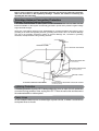
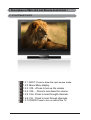
THIS PRODUCT HAS BEEN TESTED AND FOUND TO COMPLY WITH REGULATORY SAFETY CYRTIFICATIONS. This product is designed and manufactured to operate within defined design limits, and misuse may result in electric shock or fire. To prevent the product from being damaged, the following rules should be observed for the installation, use and maintenance of the product. Read the following safety instructions before operating the display. Keep these instructions in a safe place for future reference. • To avoid the risk of electric shock or component damage, switch off the power before connecting other components to the LCD TV. • Unplug the power cord before cleaning the LCD TV. A damp cloth is sufficient for cleaning the LCD TV. Do not use a liquid or a spray cleaner for cleaning the product. Do not use abrasive cleaners. • Always use the accessories recommended by VISIONQUEST to insure compatibility. • When moving the LCD TV from an area of low temperature to an area of high temperature, condensation may form on the housing. Do not turn on the LCD TV immediately after this to avoid causing fire, electric shock or component damage. • Do not place the LCD TV on an unstable cart, stand, or table. If the LCD TV falls, it can injure a person and cause serious damage to the appliance. • A distance of at least 3 feet should be maintained between the LCD TV and any heat source, i.e. radiator, heater, oven, amplifier etc. Do not install the product close to smoke. Operating the product close to smoke or moisture may cause fire or electric shock. • Slots and openings in the back and bottom of the cabinet are provided for ventilation. To ensure reliable operation of the LCD TV and to protect it from overheating, be sure these openings are not blocked or covered. Do not place the LCD TV in a bookcase or cabinet unless proper ventilation is provided. • Never push any object into the slot on the LCD TV cabinet. Do not place any objects on the top of the product. It could short circuit parts causing a fire or electric shock. Never spill liquids on the LCD TV. • The LCD TV should be operated only from the type of power source indicated on the label. If you are not sure of the type of power supplied to your home, consult your local power company. • The power cable must be replaced when using different voltage from that specified in the User Manual. For more information, contact VISIONQUEST. • The LCD TV is equipped with a three-pronged grounded plug, a plug with a third (grounding) pin. This plug will fit only into a grounded power outlet as a safety feature. If your outlet does not accommodate the three-wire plug, have an electrician install the correct outlet, or use an adapter to ground the appliance safely. Do not defeat the safety purpose of the grounded plug. • Do not overload power strips and extension cords. Overloading can result in fire or electric shock. • The wall socket should be installed near the equipment and should be easily accessible. • Do not touch the power cord during lightning. To avoid electric shock, avoid handling the power cord during electrical storms. • Unplug the unit during a lightening storm or when it will not be used for long period of time. This will protect the LCD TV from damage due to power surges. • Do not attempt to repair or service the product yourself. Opening or removing the back cover may expose you to high voltages, the risk of electric shock, and other hazards. If repair is required, please contact VISIONQUEST and refer all servicing to qualified service personnel. • Keep the product away from moisture. Do not expose this appliance to rain or moisture. If water penetrates into the product, unplug the power cord and contact VISIONQUEST. Continuous use in this case may result in fire or electric shock. • Do not use the product if any abnormality occurs. If any smoke or odor becomes apparent, unplug the power cord and contact VISIONQUEST immediately. Do not try to repair the product yourself. • Avoid using dropped or damaged appliances. If the product is dropped and the housing is damaged, the internal components may function abnormally. Unplug the power cord immediately and contact VISIONQUEST for repair. Continued use of the product may cause fire or electric shock. • Do not install the product in an area with heavy dust or high humidity. Operating the product in environments with heavy dust or high humidity may cause fire or electric shock. • Hold the power connector when removing the power cable. Pulling the power cable itself may damage the wires inside the cable and cause fire or electric shock. When the product will not be used for an extended period of time, unplug the power connector. • To avoid risk of electric shock, do not touch the connector with wet hands. • Insert batteries in accordance with instructions while using the remote control. Incorrect polarities may cause damage and leakage of the batteries, operator injury and contamination of the remote control. • If any of the following occurs, please contact VISIONQUEST: z The power connector fails or frays. z Liquid sprays or any object drops into the LCD TV. z The Display is exposed to rain or other moisture. z The Display is dropped or damaged in any way. z The performance of the Display changes substantially. • Operating environment: Temperature: 40°F ~ 95°F, Humidity: 10% to 90% non-condensing, Altitude: 0~10,000 ft. 1 Note: In some countries or regions, the shape of the power plug and power outlet may sometimes differ from that shown in the explanatory drawings. However, the method of connecting and operating the unit is the same. Television Antenna Connection Protection External Television Antenna Grounding If an outside antenna/satellite or cable system is to be connected to the LCD TV, make sure that theantenna/satellite or cable system is electrically grounded to provide some protection against voltage surges and static charges. Article 810 of the National electrical Code, ANSI/NFPSA 70, provides information with regard to proper grounding of the mast and supporting structure, grounding of the lead-in wire to an antenna discharge unit, size of the grounding conductors, location of antenna discharge unit, connection to grounding electrodes, and requirements of the grounding electrode. GROUND CLAMP ANTENNA LEAD-IN WIRE A NTENNA DISCHARGE UNIT (NeC SeCTION 810-20) GROUNDING CONDUCTORS (NeC SeCTION 810-21) GROUND CLAMPS POWER SERVICE GROUNDINE ELECTRODE SYSTEM ELECTRIC SERVICE EQUIPMENT (NeC ART 250, PART H) Lightning Protection For added protection of your LCD TV during a lightning storm or when it is left unattended or unused for long periods of time, unplug the LCD TV from the wall outlet and disconnect the antenna/satellite or cable system. Power Lines Do not locate the antenna near overhead light or power circuits, or where it could fall into such power lines or circuits. 2 Opening the Package The VISIONQUEST TV is packaged in a carton. Any standard accessories are packed separately in another carton. The weight of the LCD display is approximately 31.5Kg. Since the glass can be easily scratched or broken, please handle the product gently. Never place the unit on a surface with the glass facing downwards unless it is on protective padding. When opening the carton, check that the product is in good condition and that all standard accessories and items are included. Save the original box and all packing materials for future shipping needs IMPORTANT: Save the original box and all the packing material for future shipping needs. Package Contents VISIONQUEST HDTV Remote Control by Universal electronics Audio Video Cable (yellow, red and white connectors) Power Cord This User guide Quick Setup guide Registration Card Batteries 3 Additional VISIONQUEST Certified Accessories for the VISIONQUEST HDTV are sold separately: Wall Mounts High Definition Cables extra or replacement Remote Installation Preparation Please read the user manual carefully before performing the installation. The power consumption of the display is approximately 350 watts, please use the power cord designated for the product. When an extension cord is required, use one with the correct power rating. The cord must be grounded and the grounding feature must not be defeated. The product should be installed on a flat surface to avoid tipping. Space should be maintained between the back of the product and the wall for proper ventilation. If you would like to mount the TV to the wall, please see “Preparing the LCD for Wall Mounting” below for additional information. Avoid installing the product in the kitchen, bathroom or other places with high humidity, dust or smoke, so as not to shorten the service life of the electronic components. Please ensure the product is installed with the screen in landscape orientation. Any 90° clockwise orcounterclockwise installation may induce poor ventilation and excessive component damage. Preparing Your LCD TV for Wall Mounting The VISIONQUEST can either be kept on the stand base or mounted to the wall for viewing. If you choose to mount the HDTV to the wall, please follow the instructions below for removing the base stand. To remove the stand base: 1. Unplug all the cables and cords from your LCD TV. 2. Place the LCD TV face down on a soft and flat surface (blanket, foam, cloth, etc) to prevent any damage to the display. see Figure 3.3a 3. Remove the 6 screws on the back panel of the TV located near the bottom so that the base stand can be removed. (see Figure 3.3a) 4. gently pull the stand away from the di splay by grasping firmly to the base. see Figure 3.3b 5. Now the display can fit securely to a mount (sold separately) by utilizing the mounting holes in the center of the back panel of the display (see Figure 3.3b). Please make sure to read the directions of your specific wall mount to properly hang the HDTV. Make sure the wall mount is rated to support at least 31.5Kg. 4 CONTENTS 1. Descriptions of Main Unit and Remote-Control Unit..................................................6 1.1 Front Panel Control ..................................................................................................6 1.2 Remote-Control Unit.................................................................................................7 1.3 Illustration of the Interface Panel................... ...........................................................9 2. Connection and Preparation........................................................................................10 2.1 Connect Antenna or Video Facility..........................................................................10 2.2 Battery Installation of Remote-Control Unit.............................................................10 2.3 Auto Search the Channels.........................................…..........................................10 ....................................................................................................... 11 3. Connecting Equipment 4. Specifications...............................................................................................................18 5. The OSD Menus.............................................................................................................19 6. PC display mode............................................................................................................29 7. Trouble Shooting.....................………………...............................................................3 30 5 1. Descriptions of Main Unit and Remote-Control Unit.1 1.1 Front Panel Control 1.2.1. INPUT: Press to show the input source mode. 1.2.2. Menu:Menu display. 1.2.3. VOL +:Press to turn up the volume 1.2.4. VOL - : Press to turn down the volume. 1.2.5. CH+: Press to scan throught channels. 1.2.6. CH- : Press to scan through channels. 1.2.7.POWER: Press to turn on and off the TV. 6 .2 Remote-Control Unit TV PC HDMI Lock Recall List MTS EPG 7 CC POWER MUTE 0~9 DASH Source VOL+/VOLCH+/CHFAVS ZOOM MENU Enter Ÿ ź Ż Ź TV PC HDMI OK EXIT Recall DISPLAY LOCK LIST MTS EPG CC Freeze SLEEP PMODE SMODE Press this button to switch on the TV when at standby mode or enter standby mode. Press this button to mute or restore sound. Press the number buttons to select a channel. Press this button to select the sub-channel.(for example:10-1) Press this button to switch among TV broadcast, AV input program and other source. Volume decrease or increase choice. Press these buttons to select channels in descending or ascending order. Favorite television programs. Press this button to select the desired display mode. Press this button to enter the menu screens for various optional adjust able settings. Press this key enters chose item. Menu up. Menu down. Menu right. Menu left. Press this button to direct enter the desired TV mode. Press this button to direct enter the desired PC mode. Press this button to direct enter the desired HDMI mode. Press this button enters chose item. Press this button to exit from the current menu. Switch between the current TV channel and the last. . Show that the current mode of information. Press this button to lock the channel you want . Press this button to preview the channel list. Mono,Stereo and Sap. Use EPG button on the remote control to display the EPG menu directly. Press this button to open or close caption. Press this button to select freeze on or off. Press this button to set the sleep timer. When the preset length of time has passed, the TV set enters standby mode. Press this button to select the desired picture mode. Press this button to select the desired sound mode. 8 1.3 Illustration of the Interface Panel Back panel control 1 2 3 4 5 6 7 8 9 10 HDMI1 HDMI2 PC-VGA PC-AUDIO CVBS+AUDIO(R+L) YPBPR+AUDIO(R+L) AUDIO(R+L)-OUT S-VIDEO SPDIF TV NOTE:R=Right audio(Red);L=Left audio(White).S-video and CVBS share a audio . 9 2. Connections and Preparation 2.1 Connect Antenna or Video Facility 1. Use 75ȍ coaxial cable plug or 300-75ȍ impedance converter to plug in antenna input terminal on the rear of the cabinet. 2. Connect the video facility to the audio, video in jack on the rear of the cabinet. 2.2 Battery Installation of Remote-Control Unit 1. Turn the remote-control unit upside down. Scratch the grip of the battery compartment 2. Install two new 1.5V AAA batteries, make sure the anode and cathode of the batteries matches the “+”, “–” marks inside the battery compartment. Or not it would damage the unit. 3. Close the battery compartment cover. 2.3 Auto Search the Channels 1. Press the POWER On/Off button on the local machine or Remote-Control Unit. 2. Press the MENU button on the remote-control unit, then the screen displays the OSD menu. Select your native language in Menu Language which is in the Setup directory 3. Start Auto Channel Search 10 3. Connecting Equipment 3.1 - Which Video Connection Should I Use? This HDTV has six different ways to connect your video equipment from a basic connection to the most advanced for digital displays. ConnectionQuality(type) Connector Description Digital HD (HDMI - High-Definition Multime-dia Interface) - It is the first and only industry-supported, uncompressed, all-digital audio/video interface. HDMI provides an interface between any audio/video source, such as a set-top box, DVD player, or A/V receiver and an audio and/or video monitor, such as a digital television (DTV), over a single cable. best(digital) DTV Coaxial RF.When used for MPEG2 encoded bit streams from ATSC broadcast programming, this input takes advantage of the High Definition content. best(digital)Left Analog RGB (VGA) - This video input has seperate red, green and blue color components. The signal carries horizontal and vertical sync information on the green signal. This is most commonly used for PC input Analog HD (Component) - The video signal is separated into three signals, one containing the black-and-white information and the other two containing the color information. This enhancement over S-Video takes advantage of the superior picture provided by progressive scan DVD players and HDTV formats. S-Video (AV)- The video signal is separated into two signals, one containing the black-and-white information and the other containing the color information. Separating the color in this way avoids ‘cross color’ effects where closely spaced black and white lines are erroneously displayed in color. It also enables text to be displayed more sharply. AV (Composite) - The complete video signal is carried through this single pin connector. This is the most commonly used video connection. TV Coaxial RF. This is the connection for standard NTSC TV using antenna or cable. If you have a VCR, you can connect your antenna/cable to the VCR RF Input and connect the VCR RF Output to this connector. best(analog) better(analog) good(analog) good(analog) good(analog)Right 11 3.2 - Connecting Your DVD Player you have several options for connecting your DVD player to your new HDTV – HDMI (Digital HD), YPBPR (Analog HD), S-Video (AV), and Composite (AV) inputs. based on your home theater configu-ration, you can decide which option is the right one for you. 3.2.1 - Using HDMI (Digital HD) DVD players that have a digital interface such as HDMI (High-Definition Multimedia Interface) should be connected to the HDMI input of the HDTV for optimal results. Connecting DVD Player (Best): 1. Turn off the power to the LCD TV and DVD player. 2. Connect a HDMI cable to the HDMI output of your DVD player and the other end to the HDMI input (white color area) in the rear of your LCD TV. 3. Turn on the power to the LCD TV and your DVD player. 4. Select Digital HD using the INPUT button on the front of the LCD TV or directly by pressing the SOURCE button on the Remote Control. Note: Refer to your DVD player user manual for more information about the video output requirements of the product. 12 For DVD Players with DVI: 1. Turn off the power to the LCD TV and DVD player. 2. Using a HDMI-DVI cable, connect the DVI end to your DVD Player and the HDMI end to the HDMI input (located in the white area) in the rear of your LCD TV. 3. Using an audio cable (white and red connectors), connect cable to the audio output connecters associated with the DVI out put on the rear of your DVD Player, and connect the other end to the audio c onnectors (white area) associated with the HDMI input in the rear of your LCD TV. 4. Turn on the power to the LCD TV and your DVD Player. 5. Select digital HD using the input button on the front of the LCD TV or directly by pressing the SOURCE button on the remote control. 13 3.2.2 - Using Component (Analog HD1) Video Connecting DVD Player (Better): +'0, +'0, 9*$,1 $8',2,1 5 / &9%6 < 3% 35 5287 /287 5 / 69,'(2 63',) 79 1. Turn off the power to the LCD TV and DVD player. 2. Using the connectors in the green color area, connect the Y (green color) connector on the rear of your DVD player to the corresponding Y (green color) connector in the Component Analog YPBPR1 group (green color band) in the rear of your LCD TV. 3. Connect the Pb (blue color) connector on the rear of your DVD player to the corresponding Pb (blue color) connector in Component Analog YPBPR group (green color band) in the rear of your LCD TV. 4. Connect the Pr (red color) connector on the rear of your DVD player to the corresponding Pr (red color) connector in the YPBPR Analog HD group (green color band) in the rear of your LCD TV. 5. Connect the R (red color) and L (white color) audio connectors on the rear of your DVD player to the R (red color) and L (white color) audio input connectors in the Component Analog YPBPR group (green color band) in the rear of your LCD TV . 6. Turn on the power to the LCD TV and DVD player. 7. Select YPBPR Analog HD using the INPUT button on the remote or front of the LCD TV or directly by pressing the SOURCE button on the Remote Control. Note: a) If you are already using the YPBPR Analog HD input for another component, you do not want to use the YPBPR Analog HD input for the DVD player, you can connect the DVD player to the YPBPR Analog HD connections coded by the blue color area. b) Refer to your DVD player user manual for more information about the video output requirements of the product. 14 3.2.3 - Using Composite (AV) Video Connecting DVD Player (Good): +'0, +'0, 9*$,1 $8',2,1 5 / < 3% &9%6 5287 /287 35 5 / 69,'(2 63',) 79 1. Turn off the power to the LCD TV and DVD player. 2. Connect the S-Video jack on the rear of your DVD player to the S-Video jack in the AV In group on the side of your LCD TV. 3. Connect the R (red color) and L (white color) audio connectors on the rear of your DVD player to the R (red color) and L (white color) audio input connectors in the side of your LCD TV. 4. Turn on the power to the LCD TV and DVD player. 5. Select AV using the INPUT button on the remote or front of the LCD TV or directly by pressing the SOURCE button on the Remote Control . Note: Refer to your DVD player user manual for more information about the video output requirements of the product. 15 3.2.4 - Using Your Antenna or Cable TV 1. Turn off the power to your LCD TV. 2. Connect the coaxial (RF) connector from your antenna, cable or cable box to the TV connector on the rear of your LCD TV. 3. Turn on the power to your LCD TV. 4. Select TV using the INPUT button on the front of your LCD TV or directly by pressing the TV button on the Remote Control. 3.2.5 - Using the Antenna or Cable through Your VCR +'0, +'0, 9*$,1 $8',2,1 5 / &9%6 < 3% 35 5287 /287 5 / 69,'(2 63',) 79 Note: If you have an off-air antenna or cable TV, connect the off-air antenna or TV cable to the RF connec tor on the rear of your VCR. 16 3.5 - Connecting a Computer +'0, +'0, 9*$,1 $8',2,1 5 / &9%6 < 3% 35 5287 /287 5 / 69,'(2 63',) 79 VGA 1. Turn off the power to your LCD TV and Computer. 2. Connect a 15-pin D-sub RGB (VGA) cable to the RGB output of your computer and the other end to the RGB input (purple area) in the rear of your LCD TV. 3. Connect the Audio Out on your computer to the RGB Audio (purple band) at the rear of your LCD TV. 4. Turn on the power to your LCD TV and computer. 5. Select RGB using the INPUT button on the front of your LCD TV or directly by pressing the SOURCE button on the Remote Control. Note: a) For the best picture quality when connecting a computer through RGB, set your computer timing mode. Please refer to the graphic Card’s user guide for additional information on how to set the timing mode. b) Refer to your computer user manual for more information about the video output requirements of the product. c) Stereo mini jack cable is not included and can be purchased at an electronic store. 17 4. Specifications Items Relevant illustrations Screen size, visible 47“LCD TV Screen format 16:9 Resolution 1920X1080 Maximum contrast ratio Active Display Area Maximum brightness Response time The whole machine parameters 1000:1 1039.68(H)X584.82(V) 500 cd/m² 8ms Display colors Maximum viewing angle Maximum lifetime of Dimension (packed) Accessories 16.77M 178° (Horizontal) / 178° (Vertical) 30,000 hours 1244X350X905mm Remote-Control, Power cord, Attention card,regidtration card User Guide, quick Set up Guide,batteries Power requirement Normal Power Dissipation Standby Power Dissipation TV system AC 100̚240V, 50/60Hz 350W ˘3W NTSC +ATSC Audio Output 2×10W +2×5W OSD language TV English/French/Spanish Local control keys AV INPUT,MENU , VOL+, VOL-,CH+, CH -,Power HDMI1,HDMI2;ONE-ROAD S-VIDEO;CVBS IN;YPBPR;SPDIF. PC-Audio IN;PC-VGA IN two-road L/R audio IN and one-road L/R audio OUT Note: All specifications are subject to change without notice. 18 . 5. The OSD Menu See the table for details: PICTURE menu -Press MENU to display the OSD menu, to select the menu PICTURE,press -Press MENU to return to the main menu from the submenu. to enter the submenu. Picture Mode Press to select picture mode.Vivid,Standard,Mild,Custom .Press ENTER to confirm and return to preview menu. Contrast Press to adjust the contrast. Brightness Press to adjust the brightness. Saturation Press to adjust the saturation. Tint Press to adjust the Tint. Sharpness Press to adjust the Sharpness. Color Temp Press to select the color temp.normal,cool,warm.press ENTER to confirm. 19 Audio menu -Press MENU to display the OSD menu, to select the menu Audio, press -Press MENU to return to the main menu from the submenu. to enter the submenu. Audio Mode Press to select Audio mode.Music,Standard,Custom,Sports,Movie .Press ENTER to confirm and return to preview menu. Bass Press to adjust the Bass. Treble Press to adjust the Treble. Balance Press to adjust the Balance. Surround Press to select Surround on or off.Press ENTER to confirm and return to preview menu. AVL Press to select AVL on or off.Press ENTER to confirm and return to preview menu. SPDIF Type Press to select SPDIF Type PCM or RAW.Press ENTER to confirm and return to preview menu. Audio Language Press to select Audio language .Press ENTER to confirm and return to preview menu. 20 Time menu -Press MENU to display the OSD menu, to select the menu Audio,press -Press MENU to return to the main menu from the submenu. to enter the submenu. Sleep Press to select Sleep 10ms,20ms,30ms,40ms,50ms,60ms,90ms,120ms or off. Press ENTER to confirm and return to preview menu. Time Zone Press to select Time Zone mountain,central,alaska,eastern,hawaii,palific. Press ENTER to confirm and return to preview menu. Daylight Saving Time Press to select Daylight Saving Time on or Off.Press ENTER to confirm and return to preview menu. Data/Time Press to select Audio language .Press ENTER to confirm and return to preview menu. 21 SETUP menu -Press MENU to display the OSD menu, to select the menu SETUP,press -Press MENU to return to the main menu from the submenu. Menu Language Press to select the Menu Language.english,French/Spanish. Menu Opacity Press to select the Menu Opacity. Zoom Mode Press to enter the submenu. to select the Zoom Mode.normal,wide,zoom. DNR Press to select the DNR.off,minimum,maximum,medium. Closed Caption Press to enter the Closed Caption menu. CC Mode Press to select the CC Mode. Basic Selection Press to select the Basic Selection.Off,CC1,CC2,CC3,CC4,TEXT1,TEXT2,TEXT3,TEXT4. Advanced Selection Press to select the Advanced Selection. Option Press to enter the Option menu. 22 banklight Press to adjust the banklight. Restore Default Press to restore the factory mode . Lock menu Enter Password press digital button enter password and Press to check password.the password of factory mode is "0000". Change Password Press to change password. 23 System Lock Press to select the system lock on/off. US Press to select and enter the US menu. TV Press to adjust TV. MPAA Press to select the MPAA. Canada Press to select and enter the Canada menu. Canada english Press to select the Canada english. Canada French Press to select the Canada French. RRT seting Press to select and enter the RRT seting menu. 24 Humor level Press to select and enter the Humor level menu. intellgence level Press to select and enter the intellgence level menu. Reset Press Press to select and enter the reset menu. to select No/Yes and press ENTER to confirm.this function restore the RRT setting. 25 Channel menu Antenna Press to select Cabel and Air. AUTO Scan Press to select and enter the auto scan menu. Cable system Press to select cable system.AUTO HRC,IRC,STD. Start to Scan Press to select and enter the Start to scan menu. 26 Favorite Press to select and enter the Favorite menu. Show/Hide Press to select and enter the Show/Hide menu. Channel NO. Press to select Channel NO. Channel Lable Press to select and enter the Channel Lable menu. Press to select the location.and press to edit. 27 PICTURE menu under PC SETUP menu under PC PC Press to select the PC and press to enter the PC menu. H-Pos Press V-Pos to adjust the H-Pos. Press Clock to adjust the V-Pos Press to adjust the Clock. Phase Press to adjust the Phase. AUTO Press to select the AUTO and press to enter the AUTO menu. 28 6. PC display mode Resolution Horizontal Frequency(K HZ) 48.36 Vertical Frequency(K HZ) 60 Pixel Clock(MHZ) Standard mode 65.00 VESA Guidelines 56.48 70 75.00 VESA Standard 60.02 75 78.75 VESA Standard 63.981 60 80.45 VESA Guidelines 79.976 75 85.41 VESA Standard 47.7 60 85.5 VESA Guidelines 1400X1050 64.7 60 101.0 VESA Guidelines 1680X1050 64.7 60 119.0 VESA Guidelines 1920X1080 67.5 60 148.5 VESA Guidelines 1024 x768 1280 x768 1360X768 29 7. Trouble Shooting Before arranging for service, firstly know the status and then check simply as follows: Problems Check No picture or sound. Check if the power supply is plugged in. Check if the power switch is in “on” position. Picture is OK, but no sound Check if the volume control is set to the minimum or mute position. Remote control doesn’t work No TV signal No external video signal Picture lacks color or picture too dark Check if the power switch is in “on” position. Check if the batteries are out of use or not connected well. Make sure that there is no strong light striking the sensor window of remote control unit. Check there are no obstacles between the sensor window and remote control unit. Check if the INPUT button is set to TV status. Check if the antenna is well connected. Check if you installed the TV correctly. Check if you installed the TV correctly. Check if the INPUT button is set to AV position. Check color, brightness and contrast controls are correctly adjusted. All channels lose color Intermittently Check if the antenna is broken. Check if the antenna is disconnected. Check if the antenna is damaged. Poor reception, loss of color with certain channels Diagonal stripes appear on picture Check if channels are correctly tuned. Picture has ‘snow’ Check if the antenna is broken. Check if the antenna is disconnected. Check if the antenna is damaged. Ghost images appear The receiver may be affected by interference (e.g. from nearby radio broadcasting transmitter or from another TV receiver). Check if the antenna direction has been changed by a storm or strong wind, etc. (because ghost images are caused by the arrival at the antenna of both the signal which has traveled directly from the transmitter and the signal which has been reflected from a hill or a large building. The direction of the antenna should be chosen for minimized ghosting.) 30