1
STEP-200 User Manual
Version 3.0
02/2001
STEP-200
2-axis stepping/servo motor control card
User Manual
Version 3.0 02/2001 Edition
Driver update : http://www.icpdas.com
Warranty: All products manufactured by ICP DAS are warranted against
defective materials for one year from the date of delivery to the original
purchaser
Warning: ICP DAS assumes no liability for damage consequent to the
use of this product. ICP DAS reserves the right to change this manual at
any time without notice. The information furnished by ICP DAS is
believed to be accurate and reliable. However, no responsibility is
assumed by ICP DAS for it’s use, nor for any infringements of patents or
other rights of third parties resulting from it’s use.
Copyright
Copyright 2001 by ICP DAS. All right are reserved
Trademark
The names used for identification only maybe registered trademarks of
their respective companies.
http://www.icpdas.com
-1-
ICPDAS
STEP-200 User Manual
Version 3.0
02/2001
STEP200 2-axis Stepping/Servo Motor Control Card
STEP200 card is a 2-axis command-type stepping motor control card, it
also can be used in servo motor control (pulse input type). This card has an
embedded CPU which perform motion commands transfered from PC to
increase the system performance. A 2Kbytes-FIFO is introduced as command
buffer. This buffer can provide 1360ms buffer time. Therefore, STEP200 card
is design for windows operation system. STEP200 card provide DOS,
windows 95 and windows NT driver, let you have real time motion control
solution in windows system.
Features
•
2-axis independent, simultaneous stepping motor control / servo motor
control(pulse input type)
• step rate : 1pps~250Kpps
32
• Max. step count : 2 − 1 steps
• DOS, windows 95, windows NT driver
• embedded CPU
• command type interface
• linear, circular interpolation
• automatic trapezoidal acceleration / deceleration
• output pulse modes : CW/CCW or pulse / direction
• output polarity can be programmable
• 2500Vrms optical isolated signal output
• 5 optical isolated digital inputs per axis for limit switches
http://www.icpdas.com
-2-
ICPDAS
STEP-200 User Manual
Version 3.0
02/2001
Contents
1. Introduction
1.1 System Block Diagram
1.2 DDA technology
2. Hardware setup
2.1 Address selection
2.2 Register of STEP200 card
2.3 Hardware configuration
2.3.1 Limit switch configuration
2.3.2 Output pulse mode configuration
2.3.3 Direction configuration
2.3.4 Turn Servo ON/OFF (Hold ON/OFF)
2.3.5 Protection
2.4 Connection
3. Software
3.1 Functions
3.1.1 Loading and unloading driver commands(only for windows)
3.1.2 Setting commands
3.1.3 Stop commands
3.1.4 Simple motion commands
3.1.5 Interpolation commands
3.1.6 Others
3.1.7 New Command
3.2 Start up and end of program
4. Driver
DOS Driver(C,C++)
Windows 95 Driver
Windows NT Driver
5. Example
5.1 DOS example
5.2 Windows example
http://www.icpdas.com
-3-
ICPDAS
STEP-200 User Manual
Version 3.0
02/2001
1. Introduction
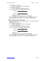
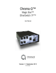
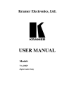
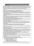
1.1 System Block Diagram
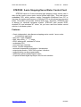
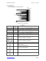
STEP200 Stepping motor control card is a micro-computer controlled, 2
axes pulse generation card. It includes a 2Kbytes-FIFO to receive motion
command from host PC, a micro-computer for profile generation and
protection, two axes DDA chip to execute DDA function when interpolation
command is called, 2500Vrms optical isolation inserted for industrial
application.
CPU
2K FIFO
DDA Chip
Profile Generation
Interface Buffer
X-axis
Protection
ISA
BUS
DDA Chip
CPU Status
Optical
Isolation
Y-axis
Limit Switch
Input Port
Connector
Limit Switch Signal
Limit Switch
Input Port
Figure(1) block diagram of STEP200
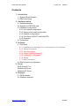
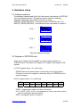
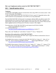
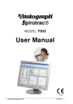
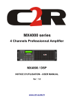
1.2 DDA Technology
The DDA chip is heart of STEP200 card, it will generate equal-space
pulse train corresponding to specific pulse number during a DDA period.
This mechanism is very useful to execute pulse generation and
interpolation function. The DDA period can be determined by DDA cycle.
Table(1) shows the relation among DDA cycle, DDA period and output
pulse rate. When DDA cycle set to 1, the DDA period is equal to 8.192ms.
The output pulse number can be set to 0~2047, therefore the maximum
output pulse rate will be 249.877kpps. The minimum output pulse rate is
0.96pps when set DDA cycle=254 (DDA period = 1040.384ms).
DDA period
DDA cycle
X pulse (n=4)
Y pulse (n=12)
Figure(2) DDA mechanism
http://www.icpdas.com
-4-
ICPDAS
STEP-200 User Manual
Version 3.0
02/2001
Table(1) The Relation among DDA cycle, DDA period and output pulse rate.
DDA cycle
DDA period
Max. pulse
Min. pulse rate (n=1)
rate(n=2047)
1
8.192ms
249877pps
122pps
2
12.288ms
166585pps
81pps
3
16.384ms
.
.
.
.
.
.
N
(N+1)*4.096ms 2047/(DDA period)
1/(DDA period)
.
.
.
.
254
1040.384ms
1967pps
0.96pps
The DDA cycle can be set by MSTEP2_SET_VAR(DDA_cycle, Acc_Dec,
Low_Speed, High_Speed) command which decribed in charpter 3. The
selection criterion of DDA cycle describes as following.
(1) The required max. output pulse rate.
V max
PRmax =
60 * N
2047
PRmax =
( DDAcycle + 1) * 4. 096ms
PRmax : max. output pulse rate.
Vmax : max. speed (rpm).
N
: the pulse number of stepping motor per revolution.
(pulse/rev).
2. The required speed resolution.
The maximum output pulse number is Np(0~2047), therefore
the speed resolution is Vmax(max. speed)/Np. The DDA cycle
can obtain as following.
Np
PRmax =
( DDAcycle + 1) * 4. 096ms
3. Large DDA cycle (DDA period), it will occur vibration between
different pulse input which generally can be observed during
acceleration or deceleration. So, the small DDA cycle , the
smooth acceleration/deceleration curve as long as the speed
resolution can be acceptable.
Example: Stepping Motor
The specification of stepping motor is 500 pulse/rev, max. speed 500
rpm, speed resolution 2 rpm.
http://www.icpdas.com
-5-
ICPDAS
STEP-200 User Manual
Version 3.0
02/2001
The required max. pulse rate
PRmax = 500 rpm/60 * 500 = 4166.67 pps
The maximum output pulse
Np = 500rpm/2rpm =250 pulse number
The DDA cycle can be calculated by follow equation
Np
PRmax =
( DDAcycle + 1) * 4. 096ms
250
4166.67 =
( DDAcycle + 1) * 4. 096ms
DDA cycle = 14
High Speed = 256 pulse (4166.67*15*0.004096)
The above results means that maximum speed is 500rpm when send
command MSTEP2_SET_VAR(14, 1, 10, 256) to STEP200 card.
Example: Pulse type input Servo Motor
The specification of servo motor is 4000 pulse/rev, max. speed 3000 rpm,
speed resolution 2 rpm.
The required max. pulse rate
PRmax = 3000 rpm/60 * 4000 = 200,000 pps
The maximum output pulse
Np = 3000rpm/2rpm =1500 pulse number
The DDA cycle can be calculated by follow equation
Np
PRmax =
( DDAcycle + 1) * 4. 096ms
1500
200,000 =
( DDAcycle + 1) * 4. 096ms
DDA cycle = 1
High Speed = 1638 pulse (200,000*2*0.004096)
The above results means that maximum speed is 3000rpm when send
command MSTEP2_SET_VAR(1, 5, 20, 1638) to STEP200 card.
http://www.icpdas.com
-6-
ICPDAS
STEP-200 User Manual
Version 3.0
02/2001
2 Hardware setup
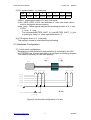
2.1 Address selection
The address is determined by A3~A9, there exist a dip switch on STEP200
card for address selection. The address can be select as following
examples. Relatively, this address must be set using
MSTEP2_REGISTRATION( ) command to select STEP200 card. The
MSTEP2_REGISTRATION( ) command has been described in chapter 3.
0
300H =
ON
1
1 2 3 4 5 6 7 8
A3 A4 A5 A6 A7 A8 A9
0
240H =
ON
1
1 2 3 4 5 6 7 8
A3 A4 A5 A6 A7 A8 A9
0
280H =
ON
1
1 2 3 4 5 6 7 8
A3 A4 A5 A6 A7 A8 A9
Figure(3) Address selection
2.2 Register of STEP200 card
There are 4 registers which resided in selected address (base) on
STEP200 card. It includes FIFO register, DI1 register, DI2 register, STS
register.
(1) FIFO register (base + 0) (write only)
STEP200 driver will send motion command by way of this register.
Please do not use this register to write any thing, or STEP200 will not
operate properly.
(2) DI1 register (base + 0) (read only)
MSB 7
6
5
/EMG
xx
xx
4
3
2
1
0 LSB
/LS14 /LS13 /LS12 /LS11 /ORG1
/ORG1 : original point switch of X-axis, low active.
/LS11, /LS12, /LS13, /LS14 : limit switches of X-axis, low active, which
must be configured as next session.
/EMG : emergency switch, low active.
http://www.icpdas.com
-7-
ICPDAS
STEP-200 User Manual
Version 3.0
(3) DI1 register (base + 1) (read only)
MSB 7
6
5
4
ystop
xstop
xx
3
2
1
02/2001
0 LSB
/LS24 /LS23 /LS22 /LS21 /ORG2
/ORG2 : original point switch of Y-axis, low active.
/LS21, /LS22, /LS23, /LS24 : limit switches of Y-axis, low active, which
must be configured as next session.
xstop, ystop : These signals indicate the operating situation of X, Y axis
in CPU.
1 : busy, 0 : stop
The commands MSTEP2_WAIT_X( ) and MSTEP2_WAIT_Y( ) just
to waiting for 'xstop' or 'ystop' signal become to '0'.
(4) STS register (base + 2) (read only)
This register is used for manufacturing and testing.
2.3 Hardware Configuration
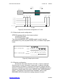
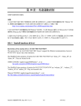
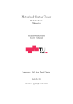
2.3.1 Limit switch configuration
Because the profile generation and protection is executed by the CPU
on STEP200 card, the limit switches must configure as following diagram.
The motion command just can work properly.
CCW/BW
CW/FW
Motor
ccm
LS11 ORG1 LS12
LS13
LS14
/LS11
/ORG1
/LS12
/LS13
/LS14
EXT_GND
X axis
/EMG
Emergency
Figure(4) Limit switch configuration of X axis
http://www.icpdas.com
-8-
ICPDAS
STEP-200 User Manual
Version 3.0
CCW/BW
02/2001
CW/FW
Motor
ccm
LS21 ORG2 LS22
LS23 LS24
/LS21
/ORG2
/LS22
/LS23
/LS24
EXT_GND
Y axis
Figure(5) Limit switch configuration of Y axis
2.3.2 Output pulse mode configuration
STEP200 card provide two kind output method.
(a) CW/CCW mode
(b) Pulse/Direction mode
The command MSTEP2_SET_MODE( modeX, modeY) provide
parameters CW_CCW (0) and PULSE_DIR (1) to define output pulse
mode.
CW
Mode = 0 (CW_CCW)
CCW
Pulse
Mode = 1 (PULSE_DIR)
Direction
Figure(6) Output pulse mode
2.3.3 Direction configuration
Sometimes, the output direction of X-axis, Y-axis is undesired
direction due to motor connection or gear train. In oder to unify the
output direction as shown in Figure(4) and Figure(5). Where CW/FW
direction is defined as toward outside from motor, CCW/BW direction is
defined as toward inside from motor. MSTEP2_SET_DEFDIR(defdirX,
defdirY ) command provide parameters NORMAL_DIR (0) and
REVERSE_DIR (0) to define the rotating direction of motor.
http://www.icpdas.com
-9-
ICPDAS
STEP-200 User Manual
Version 3.0
02/2001
2.3.4 Turn Servo ON/OFF (Hold ON/OFF)
To turn servo motor into servo ON(OFF) state, or turn stepping motor
into hold ON(OFF) state, the command
MSTEP2_SET_SERVO_ON(sonX, sonY) provide parameters ON (1)
and OFF (0) to turn ON or OFF.
2.3.5 Protection
STEP200 card is a automatic protected system.
(a) If X-aixs command is executing and moving toward CW/FW direction,
X-axis will immediately stop when LS14 is touched. To release this
protection as long as X-axis move toward CCW/BW direction.
(b) If X-aixs command is executing and moving toward CCW/BW
direction, X-axis will immediately stop when LS11 is touched. To
release this protection as long as X-axis move toward CW/FW
direction.
(c) If Y-aixs command is executing and moving toward CW/FW direction,
Y-axis will immediately stop when LS24 is touched. To release this
protection as long as Y-axis move toward CCW/BW direction.
(d) If Y-aixs command is executing and moving toward CCW/BW
direction, Y-axis will immediately stop when LS21 is touched. To
release this protection, as long as Y-axis move toward CW/FW
direction.
http://www.icpdas.com
-10-
ICPDAS
STEP-200 User Manual
Version 3.0
02/2001
2.4 Connection
(1) Pin Assignment of connector CN1
CN1
DB25
DB25/FEMALE/90
+5V
CW_PULSE1
CW_PULSE2
CCW_DIR1
CCW_DIR2
HOLD1
HOLD2
/ORG1
EXT_VCC
/ORG2
/LS11
/LS21
/LS12
/LS22
/LS13
/LS23
/LS14
/LS24
/EMG
1
14
2
15
3
16
4
17
5
18
6
19
7
20
8
21
9
22
10
23
11
24
12
25
13
EXT_GND
Figure (7) CN1 connector
Table(2)
pin name
CW_PULSE1
CCW_DIR1
HOLD1
which
axis
X
X
X
CW_PULSE2
CCW_DIR2
HOLD2
Y
Y
Y
/ORG1,
/LS11, /LS12
/LS13, /LS14
/ORG2,
/LS21, /LS22
/LS23, /LS24
/EMG
+5V
pin 1
pin 14
GND
pin 5
pin 18
EXT_VCC
pin 6
pin 19
EXT_GND
pin 13
pin 25
X
http://www.icpdas.com
Y
can be configure as CW or PULSE pin
can be configure as CCW or DIR pin
servo ON/OFF or hold ON/OFF signal 1: ON, 0:
OFF
can be configure as CW or PULSE pin
can be configure as CCW or DIR pin
servo ON/OFF or hold ON/OFF signal 1: ON, 0:
OFF
orginal point ,limit switches, low active
should be configure as Figure(4)
original point, limit switches, low active
should be configure as Figure(5)
emergency switch, low active
internal supplied voltage, only used for output
pulse. (50mA)
don't use for other device
internal ground, only used for output pulse.
don't use for other device
external power 12V~24V, used for limit switches
external ground, used for limit switches
-11-
ICPDAS
STEP-200 User Manual
Version 3.0
02/2001
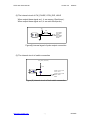
(2) The internal circuit of CW_PULSE, CCW_DIR, HOLD
When output these signal as 1, it can source 15mA(max.).
When output these signal as 0, it can sink 50mA(max.)
+5V
330
CW_PULSE1
CCW_DIR1
HOLD1
CW_PULSE2
CCW_DIR2
HOLD2
Figure(8) internal signal of pulse output connection
(3) The internal circuit of switch connection
EXT_VCC (12V~24V)
4.7K
/ORG1, /LS11, /LS12
/LS13, /LS14
/ORG2, /LS21, /LS22
/LS23, /LS24
/EMG
Figure(9) internal circuit of limit switch connection
http://www.icpdas.com
-12-
ICPDAS
STEP-200 User Manual
Version 3.0
02/2001
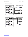
(3) Examples for connection
+5V
1
3
6
5
4
CW_PULSE1
CW +
1
4
CW -
2
3
+5V
1
3
6
5
4
CCW_DIR1
CCW +
1
4
CCW -
2
3
HOLD +
1
4
HOLD -
2
3
+5V
1
3
6
5
4
HOLD1
GND
DGND
FAN-OUT TYPE (VEXTA) DRIVER
Figure(10) fan-out type driver (VEXTA's motor driver)
+5V
COM
1
3
6
5
4
CW_PULSE1
CW/PULSE
CCW_DIR1
CCW/DIR
1
4
2
3
1
4
2
3
1
4
2
3
+5V
1
3
6
5
4
+5V
1
3
6
5
4
HOLD1
HOLD
GND
DGND
SINK TYPE DRIVER
Figure(11) Sink type driver
http://www.icpdas.com
-13-
ICPDAS
STEP-200 User Manual
Version 3.0
CN1
DB25
DB25/FEMALE/90
5V
CW_PULSE1
CW_PULSE2
CCW_DIR1
CCW_DIR2
HOLD1
HOLD2
GND
EXT_24V
PHOME1
PHOME2
PLS11
PLS21
PLS12
PLS22
PLS13
PLS23
PLS14
PLS24
PEMG
EXT_GND
1
14
2
15
3
16
4
17
5
18
6
19
7
20
8
21
9
22
10
23
11
24
12
25
13
02/2001
CN1
DB25
DB25/FEMALE/90
1A+
1A1B+
1B1C+
1C5V
EGND
2A+
2A2B+
2B2C+
2C5V
EGND
3A+
3A3B+
3B3C+
3C5V
EGND
EGND
1
14
2
15
3
16
4
17
5
18
6
19
7
20
8
21
9
22
10
23
11
24
12
25
13
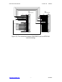
Figure (12) The connection between ENCODER3 card and STEP200
card.(for testing)
http://www.icpdas.com
-14-
ICPDAS
STEP-200 User Manual
Version 3.0
02/2001
3. Software
Directories
3.1 Functions
Constants
#define ON
#define OFF
#define CW_CCW
#define PULSE_DIR
#define NORMAL_DIR
#define REVERSE_DIR
#define FW
#define BW
#define CW
#define CCW
#define X_axis
#define Y_axis
1
0
0
1
0
1
0
1
0
1
1
2
#define READY 0
#define BUSY 1
STEP200 card is a automatic protected system.
(a)If X-aixs command is executing and moving toward CW/FW direction,
X-axis will immediately stop when LS14 is touched. To release this
protection as long as X-axis move toward CCW/BW direction.
(b)If X-aixs command is executing and moving toward CCW/BW
direction, X-axis will immediately stop when LS11 is touched. To
release this protection as long as X-axis move toward CW/FW
direction.
(c) If Y-aixs command is executing and moving toward CW/FW direction,
Y-axis will immediately stop when LS24 is touched. To release this
http://www.icpdas.com
-15-
ICPDAS
STEP-200 User Manual
Version 3.0
02/2001
protection as long as Y-axis move toward CCW/BW direction.
(d) If Y-aixs command is executing and moving toward CCW/BW
direction, Y-axis will immediately stop when LS21 is touched. To
release this protection, as long as Y-axis move toward CW/FW
direction.
http://www.icpdas.com
-16-
ICPDAS
STEP-200 User Manual
Version 3.0
02/2001
3.1.1 Loading and unloading driver commands (only for windows)
(1) MSTEP2_INITIAL( )
To load VxD driver.
(2) MSTEP2_END( )
To release VxD driver.
http://www.icpdas.com
-17-
ICPDAS
STEP-200 User Manual
Version 3.0
02/2001
3.1.2 Setting commands
(3) unsigned char MSTEP2_REGISTRATION(unsigned char cardNo,
unsigned int address);
To select the address of board and check it exist or not. 20 STEP-200
boards can be added in one system.
cardNo : board number 0~19.
address : select the address as well as hardware selected in chapter 2.
return NO : board not exist
YES : board exist
Example:
MSTEP2_REGIDTRATION(1, 0x300);
(4) MSTEP2_RESET_SYSTEM( unsigned char cardNo )
to reset STEP-200 card.
cardNo : board number 0~19.
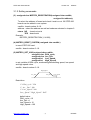
(5) MSTEP2_SET_VAR(unsigned char cardNo,
unsigned char DDA_cycle,
unsigned char Acc_Dec,
unsigned int Low_Speed,
unsigned int High_Speed)
to set variable of DDA cycle, accelerating/decelerating speed, low speed
and high speed value.
cardNo : board number 0~19.
High_Speed
Acc_Dec
Acc_Dec
Low_Speed
Restriction:
1 ≤ DDA _ cycle ≤ 254
1 ≤ Acc _ Dec ≤ 200
1 ≤ Low _ Speed ≤ 200
Low _ Speed ≤ High _ Speed ≤ 2047
default value
DDA_cycle = 10
Acc_Dec = 1
Low_Speed = 10
High_Speed = 100
http://www.icpdas.com
-18-
ICPDAS
STEP-200 User Manual
Version 3.0
02/2001
Example:
MSTEP2_SET_VAR(1, 5, 2, 10, 150);
where
DDA_cycle = 5 --> DDA period = (5+1)*4.096ms = 24.576ms
Acc_Dec = 2
--> Acc/Dec speed = 2/(24.576ms)^2 = 3311 p/s^2
Low_Speed = 10 --> low speed = 10/24.576ms = 407pps
High_Speed = 150 --> high speed = 150/24.576ms = 6107pps
(6) MSTEP2_SET_DEFDIR(unsigned char cardNo,
unsigned char defdirX,
unsigned char defdirY)
Sometimes, the output direction of X-axis, Y-axis is undesired
direction due to motor connection or gear train. In oder to unify the output
direction as shown in Figure(4) and Figure(5). Where CW/FW direction is
defined as toward outside from motor, CCW/BW direction is defined as
toward inside from motor. MSTEP2_SET_DEFDIR( ) command provide
parameters to define the rotating direction of motor.
cardNo : board number 0~19.
defdirX : X axis direction definition
defdirY : Y axis direction definition
0 : NORMAL_DIR
1 : REVERSE_DIR
(7) MSTEP2_SET_MODE(unsigned char cardNo,
unsigned char modeX,
unsigned char modeY)
STEP200 card provide two kind output method.
modeX : X axis output mode
modeY : Y axis output mode
0 : CW_CCW
CW/CCW mode
1 : PULSE_DIR
Pulse/Direction mode
CW
Mode = 0 (CW_CCW)
CCW
Pulse
Mode = 1 (PULSE_DIR)
Direction
Example:
MSTEP2_SET_MODE(1,CW_CCW, PULSE_DIR);
(8) MSTEP2_SET_SERVO_ON(unsigned char cardNo,
unsigned char sonX, unsigned char sonY)
To turn servo motor into servo ON(OFF) state, or turn stepping motor into
http://www.icpdas.com
-19-
ICPDAS
STEP-200 User Manual
Version 3.0
02/2001
hold ON(OFF) state.
sonX : X axis servo/hold on switch
sonY : Y axis servo/hold on switch
1 : ON
0 : OFF
http://www.icpdas.com
-20-
ICPDAS
STEP-200 User Manual
Version 3.0
02/2001
3.1.3 Stop Commands
(9) MSTEP2_STOP_X(unsigned char cardNo)
to stop X axis.
(10) MSTEP2_STOP_Y(unsigned char cardNo)
to stop Y axis.
(11) MSTEP2_STOP_ALL(unsigned char cardNo)
to stop X, Y axis immediatly.
This command will clear commands pending the FIFO, and then send stop
X, Y axis command to achieve immediately stop all axis.
http://www.icpdas.com
-21-
ICPDAS
STEP-200 User Manual
Version 3.0
02/2001
3.1.4 Simple motion commands
(12) MSTEP2_LSP_ORG(unsigned char cardNo,
unsigned char DIR, unsigned char AXIS)
Low speed move , and stop when ORG1/ORG2 limit switch is touched.
ORG
Low speed
Example:
MSTEP2_LSP_ORG(1, CCW, X_axis);
MSTEP2_LSP_ORG(1, CCW, Y_axis);
(13) MSTEP2_HSP_ORG(unsigned char cardNo, unsigned char DIR,
unsigned char AXIS)
High speed move , and stop when ORG1/ORG2 limit switch is touched.
ORG
high speed
Example:
MSTEP2_HSP_ORG(1, CCW, X_axis);
MSTEP2_HSP_ORG(1, CCW, Y_axis);
(14) MSTEP2_HSD_ORG(unsigned char cardNo,
unsigned char DIR, unsigned char AXIS)
High speed move , and slow down to low speed when LS12/LS22 limit
switch is touched, and then stop when reach ORG1/ORG2 limit switch.
LS12
high speed
ORG1
low speed
X axis
LS22
high speed
ORG2
low speed
Y axis
Example:
MSTEP2_HSD_ORG(1, CCW, X_axis);
http://www.icpdas.com
-22-
ICPDAS
STEP-200 User Manual
Version 3.0
02/2001
MSTEP2_HSD_ORG(1, CCW, Y_axis);
(15) MSTEP2_LSP_PULSE_MOVE(unsigned char cardNo,
unsigned char AXIS, long pulseN)
Low speed move #pulseN
#pulseN
Example:
MSTEP2_LSP_PULSE_MOVE(1, X_axis, 20000);
MSTEP2_LSP_PULSE_MOVE(1, X_axis, -2000);
MSTEP2_LSP_PULSE_MOVE(1, Y_axis, 20000);
MSTEP2_LSP_PULSE_MOVE(1, Y_axis, -2000);
where
when pulseN>0, move toward CW/FW direction
when pulseN<0, move toward CCW/BW direction
(16) MSTEP2_HSP_PULSE_MOVE(unsigned char cardNo,
unsigned char AXIS, long pulseN)
High speed move #pulseN.
high speed
#pulseN
Example:
MSTEP2_HSP_PULSE_MOVE(1, X_axis, 20000);
MSTEP2_HSP_PULSE_MOVE(1, X_axis, -2000);
MSTEP2_HSP_PULSE_MOVE(1, Y_axis, 20000);
MSTEP2_HSP_PULSE_MOVE(1, Y_axis, -2000);
where
when pulseN>0, move toward CW/FW direction
when pulseN<0, move toward CCW/BW direction
(17) MSTEP2_LSP_MOVE(unsigned char cardNo,
unsigned char DIR, unsigned char AXIS)
Low speed move toward direction DIR. It can be stop by
MSTEP2_STOP_X or MSTEP2_STOP_Y or MSTEP2_STOP_ALL
command.
Low speed
Example:
http://www.icpdas.com
-23-
ICPDAS
STEP-200 User Manual
Version 3.0
02/2001
MSTEP2_LSP_MOVE(1, CW, X_axis);
getch( );
MSTEP2_STOP_X(1);
MSTEP2_LSP_MOVE(1, CCW, Y_axis);
getch( );
MSTEP2_STOP_Y(1);
(18) MSTEP2_HSP_MOVE(unsigned char cardNo,
unsigned char DIR, unsigned char AXIS)
High speed move toward direction DIR. It can be stop by
MSTEP2_STOP_X or MSTEP2_STOP_Y or MSTEP2_STOP_ALL
command.
high speed
Example:
MSTEP2_HSP_MOVE(1, CW, X_axis);
getch( );
MSTEP2_STOP_X(1);
MSTEP2_HSP_MOVE(1, CCW, Y_axis);
getch( );
MSTEP2_STOP_Y(1);
(19) MSTEP2_CSP_MOVE(unsigned char cardNo, unsigned char dir,
unsigned char axis, unsigned int move_speed)
This command will accelerate/decelerate the selected axis’s motor to the
“move_speed”. This command can be continuously send to STEP-200 to
dynamicly change speed. The rotating motor can be stop by the
command MSTEP2_STOP() or MSTEP2_DEC_STOP().
cardNo : board number 0~9.
axis : selected axis.
1 : X axis
2 : Y axis
dir : moving direction.
0 : CW
1 : CCW
0 < move_speed <= 2040
http://www.icpdas.com
-24-
ICPDAS
STEP-200 User Manual
Version 3.0
02/2001
move speed
Acc_Dec
Example:
MSTEP2_CSP_MOVE(1, CW, X_axis, 10);
delay(10000);
MSTEP2_CSP_MOVE(1, CW, X_axis, 20);
delay(10000);
MSTEP2_CSP_MOVE(1, CW, X_axis, 30);
delay(10000);
(20) MSTEP2_SLOW_DOWN(unsigned char cardNo, unsigned char AXIS)
to decelerate to slow speed until MSTEP2_STOP_X( ) or
MSTEP2_STOP_Y or MSTEP2_STOP_ALL is executed.
SLOW_DOWN
Example:
MSTEP2_HSP_MOVE(1, CW, X_axis);
getch( );
MSTEP2_SLOW_DOWN(1, X_axis);
getch( );
MSTEP2_STOP_X(1);
(21) MSTEP2_SLOW_STOP(unsigned char cardNo, unsigned char AXIS)
to decelerate to stop.
SLOW_STOP
Example:
MSTEP2_HSP_MOVE(1, CW, Y_axis);
getch( );
MSTEP2_SLOW_STOP(1, Y_axis);
http://www.icpdas.com
-25-
ICPDAS
STEP-200 User Manual
Version 3.0
02/2001
3.1.5 Interpolation commands
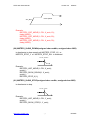
(22) MSTEP2_INTP_PULSE(unsigned char cardNo, int Xpulse, int Ypulse)
This command will move a short distance(interpolation short line) in X-Y
plane. This command provide user to generate an arbitrary curve in X-Y
plane.
Y
Y
10
(Xpulse,Ypulse)
9
3
2
X
4
8
5
6
7
1
X
Restriction:
−2047 ≤ # Xpulse ≤ 2047
−2047 ≤ #Ypulse ≤ 2047
Example:
MSTEP2_INTP_PULSE(1,20,20);
MSTEP2_INTP_PULSE(1,20,13);
MSTEP2_INTP_PULSE(1,20,7);
MSTEP2_INTP_PULSE(1,20,0);
MSTEP2_INTP_PULSE(1,15,-5);
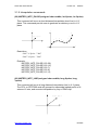
(23) MSTEP2_INTP_LINE(unsigned char cardNo, long Xpulse, long
Ypulse)
This command will move a long distance(interpolation line) in X-Y plane.
The CPU on STEP200 card will generate a trapezoidal speed profile of Xaxis and Y-axis, and execute interpolation by way of DDA chip.
Y
(Xpulse,Ypulse)
(0,0)
http://www.icpdas.com
-26-
X
ICPDAS
STEP-200 User Manual
Version 3.0
02/2001
Restriction:
−524287 ≤ # Xpulse ≤ 524287
−524287 ≤ #Ypulse ≤ 524287
Example:
MSTEP2_INTP_LINE(1,2000,-3000);
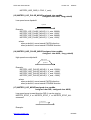
MSTEP2_INTP_LINE(1,-500,200);
(24) MSTEP2_INTP_LONG_LINE(unsigned char cardNo, long x, long y
, unsigned int speed)
This command will move a long interpolation line in X-Y plane. PC will
automaticly generate a trapezoidal speed profile of X-axis and Y-axis, and
send these profile by way of MSTEP2_INTP_PULSE( ) command.
This command only can be immediately stopped by /EMG switch.
Y
(X,Y)
(0,0)
X
speed : 0~2040
Restriction:
−2 32 + 1 ≤ # x ≤ 2 32 − 1
−2 32 + 1 ≤ # y ≤ 2 32 − 1
Example:
MSTEP2_INTP_LONG_LINE(1,20000,-30000);
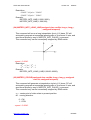
(25) MSTEP2_CIRCLE(unsigned char cardNo, long x, long y, unsigned
char dir, unsigned int speed)
This command will generate a interpolation circle in X-Y plane. PC will
automaticly generate a trapezoidal speed profile of X-axis and Y-axis, and
send these profile by way of MSTEP2_INTP_PULSE( ) command.
This command only can be immediately stopped by /EMG switch.
x, y : center point of circle relate to present position.
dir : moving direction.
0 : CW
1 : CCW
speed : 0~2040
http://www.icpdas.com
-27-
ICPDAS
STEP-200 User Manual
Version 3.0
02/2001
Y
(X,Y)
CW
X
CCW
where radius = sqrt(X^2 + Y^2)
Restriction:
−2 32 + 1 ≤ # x ≤ 2 32 − 1
−2 32 + 1 ≤ # y ≤ 2 32 − 1
Example:
MSTEP2_INTP_CIRCLE(1,2000,-2000,CW,100);
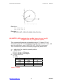
(26) MSTEP2_ARC(unsigned char cardNo, long x, long y, long R,
unsigned char dir, unsigned int speed)
This command will generate a interpolation arc in X-Y plane. PC will
automaticly generate a trapezoidal speed profile of X-axis and Y-axis, and
send these profile by way of MSTEP2_INTP_PULSE( ) command.
This command only can be immediately stopped by /EMG switch.
x, y : end point of arc relate to present position.
R : radius of arc.
if R>0 , the arc < 180degree
if R<0 , the arc > 180 degree
dir : moving direction.
0 : CW
1 : CCW
R
dir
path of curve
R>0
CW
'B'
R>0
CCW
'C'
R<0
CW
'A'
R<0
CCW
'D'
speed : 0~2040
http://www.icpdas.com
-28-
ICPDAS
STEP-200 User Manual
Version 3.0
02/2001
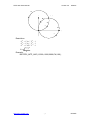
'A'
CW
Y
(X,Y)
'B'
CW
'C'
CCW
'D'
X
CCW
Restriction:
−2 32 + 1 ≤ # x ≤ 2 32 − 1
−2 32 + 1 ≤ # y ≤ 2 32 − 1
−2 32 + 1 ≤ # R ≤ 2 32 − 1
R≥
x2 + y2
2
Example:
MSTEP2_INTP_ARC(1,2000,-2000,2000,CW,100);
http://www.icpdas.com
-29-
ICPDAS
STEP-200 User Manual
Version 3.0
02/2001
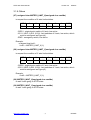
3.1.6 Others
(27) unsigned char MSTEP2_LIMIT_X(unsigned char cardNo)
to request the condition of X-axis limit switches
MSB 7
6
5
/EMG
xx
xx
4
3
2
1
0 LSB
/LS14 /LS13 /LS12 /LS11 /ORG1
/ORG1 : original point switch of X-axis, low active.
/LS11, /LS12, /LS13, /LS14 : limit switches of X-axis, low active, which
must be configured as Figure(4).
/EMG : emergency switch, low active.
Example:
unsigned char limit1;
limit1 = MSTEP2_LIMIT_X(1);
(28) unsigned char MSTEP2_LIMIT_Y(unsigned char cardNo)
to request the condition of Y-axis limit switches
MSB 7
6
5
ystop
xstop
xx
4
3
2
1
0 LSB
/LS24 /LS23 /LS22 /LS21 /ORG2
/ORG2 : original point switch of Y-axis, low active.
/LS21, /LS22, /LS23, /LS24 : limit switches of Y-axis, low active, which
must be configured as Figure(5).
Example:
limit2 = MSTEP2_LIMIT_Y(1);
(29) MSTEP2_WAIT_X(unsigned char cardNo)
to wait X-axis going to STOP state.
(30) MSTEP2_WAIT_Y(unsigned char cardNo)
to wait Y-axis going to STOP state.
http://www.icpdas.com
-30-
ICPDAS
STEP-200 User Manual
Version 3.0
02/2001
3.1.7 New Commands
(31) MSTEP2_SET_NC(unsigned char cardNo, unsigned char sw);
To set all of the following limit switches as N.C.(normal close) or
N.O.(normal open). If set as N.O., those limit switches are active low. If
set as N.C., those limit switches are active high. The auto-protection will
automatically change the judgement whatever it is N.O. or N.C..
Limit switches: ORG1, LS11, LS12, LS13, LS14, ORG2, LS21, LS22,
LS23, LS24, EMG.
cardNo : card number 0~9.
sw: 0(NO) normal open (default).
1(YES) normal close.
(32) MSTEP2_EMG_STOP(unsigned char cardNo);
This function is the same as MSTEP2_STOP_ALL(), but MSTEP2_
EMG_STOP() only can be used in timer interrupt routine.
cardNo : card number 0~9.
This command will clear all of pending commands in the buffer, and
immediately terminate all commands which is executing in STEP-200
board.
(33) MSTEP2_INTP_LINE02(unsigned char cardNo, long x, long y
, unsigned int speed
, unsigned char acc_mode)
(34) MSTEP2_INTP_CIRCLE02(unsigned char cardNo, long x, long y,
unsigned char dir, unsigned int speed,
unsigned char acc_mode)
(35) MSTEP2_INTP_ARC02(unsigned char cardNo, long x, long y, long R,
unsigned char dir, unsigned int speed,
unsigned char acc_mode)
acc_mode: 0: enable acceleration and deceleration profile
1: disable acceleration and deceleration profile
The new driver provide a set of state-machine-type interpolation
command including:
MSTEP2_INTP_LINE02
MSTEP2_INTP_CIRCLE02
MSTEP2_INTP_ARC02
These command can be set acc_mode=1 to disable the acceleration and
http://www.icpdas.com
-31-
ICPDAS
STEP-200 User Manual
Version 3.0
02/2001
deceleration profile.
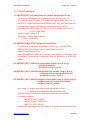
(36) unsigned char MSTEP2_INTP_STOP()
This command is to compute the interpolation service. It will return
READY(0) for interpolation command completed. And retrun BUSY(1)
for not yet complete.
(37) unsigned char MSTEP2_GET_CARD()
This command is used only for DOS in timer interrupt service (10ms) to
compute the state-machine-type interpolation command.
These 3 state-machine-type interpolation commands must use
MSTEP2_GET_CARD() (only for windows) and MSTEP2_INTP_STOP()
simultaneously. The state-machine-type interpolation commands are only set
parameters into the driver. The computing entity is in MSTEP2_GET_CARD()
(only for windows) and MSTEP2_INTP_STOP().
In windows application, when The MSTEP2_GET_CARD() command is
running in the timer interrupt routine by 10ms, it will help to calculate the
interpolation service.
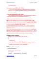
Both of DOS and windows application, User can directly call the do {} while
(MSTEP2_INTP_STOP()!=READY) to execute the computing entity. The user
can monitor something or waiting for keyboard input in the do loop. Therefore,
The user has chance to do the software stop or monitor something.
DOS application example1
MSTEP2_INTP_LINE02(CARD1,1000,1000,100,1);
do
{
show_panel();
if (kbhit()) chkey=bioskey(0); //F7=0x4100
} while ( (chkey!= 0x4100) && (MSTEP2_INTP_STOP()!=READY) );
if (chkey==0x4100) MSTEP2_STOP_ALL(CARD1);
DOS application example2
void TimerInterrupt(void)
{
MSTEP2_GET_CARD(CARD1);
show_panel();
if (kbhit())
chkey=bioskey(0); //F7=0x4100
http://www.icpdas.com
-32-
ICPDAS
STEP-200 User Manual
Version 3.0
02/2001
}
void test_intp(void)
{
MSTEP2_INTP_LINE02(CARD1,1000,1000,100,1);
do
{ } while ( (chkey!= 0x4100) && (MSTEP2_INTP_STOP()!=READY) );
if (chkey==0x4100) MSTEP2_STOP_ALL(CARD1);
}
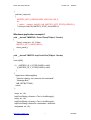
Windows application example1
void __fastcall TMSERVO::Timer1Timer(TObject *Sender)
{
Timer1->Interval = 10; //10ms
MSTEP2_GET_CARD(CARD1);
show_panel();
}
void __fastcall TMSTEP::IntpCircleClick(TObject *Sender)
{
char str[20];
if (
(MSTEP2_IS_X_STOP(CARD1)==NO)
|| (MSTEP2_IS_Y_STOP(CARD1)==NO)
)
{
Application->MessageBox(
"Motor's rotating, can't execute this command",
"Message Box",
MB_DEFBUTTON1);
return;
};
ltoa(x, str, 10);
IntpCircleDialog->Xcenter->Text = AnsiString(str);
ltoa(y, str, 10);
IntpCircleDialog->Ycenter->Text = AnsiString(str);
IntpCircleDialog->SelectDir->ItemIndex = direction;
ltoa(speed, str, 10);
http://www.icpdas.com
-33-
ICPDAS
STEP-200 User Manual
Version 3.0
02/2001
IntpCircleDialog->speed->Text = AnsiString(str);
if (IntpCircleDialog->ShowModal()==mrOk)
{
x= (long)IntpCircleDialog->Xcenter->Text.ToInt();
y= (long)IntpCircleDialog->Ycenter->Text.ToInt();
direction = IntpCircleDialog->SelectDir->ItemIndex;
speed= (unsigned int)IntpCircleDialog->speed->Text.ToInt();
//MSTEP2_CIRCLE(CARD1,x, y, (unsigned char)direction, speed);
MSTEP2_INTP_CIRCLE02(CARD1,x,y,(unsigned char)direction,speed,0);
do {Application->ProcessMessages();}
while (MSTEP2_INTP_STOP()!=READY);
}
}
http://www.icpdas.com
-34-
ICPDAS
STEP-200 User Manual
Version 3.0
02/2001
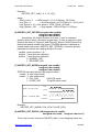
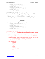
3.2 Start up and end of program
Start up program
When you are going to use STEP200 card, there are some commands
must be used firstly.
MSTEP2_INITIAL()
to load vxd driver. DOS application don't need execute this command.
MSTEP2_REGISTRATION(CARD1,0x300)
set CARD1 address, (where CARD1=1)
MSTEP2_RESET_SYSTEM(CARD1);
reset system
MSTEP2_SET_VAR(CARD1, DDA, AD, LSP, HSP);
set DDA cycle, accelerating/decelerating speed, low speed and high
speed value
MSTEP2_SET_DEFDIR(CARD1, xdir, ydir);
define direction.
MSTEP2_SET_MODE(CARD1, xmode, ymode);
define output mode.
MSTEP2_SET_SERVO_ON(CARD1, xson, yson);
set servo ON/OFF.
end of program
MSTEP2_RESET_SYSTEM(CARD1);
reset system
MSTEP2_END();
to release VxD driver. DOS application don't need execute this
command.
Example
//-----------------------------------------------------------------------------#define CARD1 1
unsigned char DDA,AD;
unsigned int LSP,HSP;
unsigned char xmode,ymode;
unsigned char xdir,ydir;
unsigned char xson,yson;
void main ()
{
DDA = 5;
AD = 5;
LSP = 10;
HSP = 120;
xmode = CW_CCW;
ymode = CW_CCW;
http://www.icpdas.com
-35-
ICPDAS
STEP-200 User Manual
Version 3.0
02/2001
xdir = NORMAL_DIR;
ydir = NORMAL_DIR;
xson = ON;
yson = ON;
//--- start up program --------------------MSTEP2_INITIAL();
//-- only uesd for windows application
MSTEP2_REGISTRATION(CARD1, 0x300);
MSTEP2_RESET_SYSTEM(CARD1);
MSTEP2_SET_VAR(CARD1, DDA, AD, LSP, HSP);
MSTEP2_SET_DEFDIR(CARD1, xdir, ydir);
MSTEP2_SET_MODE(CARD1, xmode, ymode);
MSTEP2_SET_SERVO_ON(CARD1, xson, yson);
.
.
.
//--- end of program ---------------------------MSTEP2_RESET_SYSTEM(CARD1);
MSTEP2_END();
//-- only uesd for windows application
}
http://www.icpdas.com
-36-
ICPDAS
STEP-200 User Manual
Version 3.0
02/2001
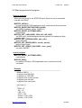
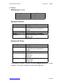
4. Driver
DOS Driver (C, C++)
Item
Header file
Library file
Example file
File
mstep2.h
mstep2.lib
mtest.prj
Windows 95 Driver
Item
Header file
ImportLibrary file
Dynamic Link Library
VxD file
Example file
File
step32.h
step32.lib
bcstep32.lib (only for Borland C++
series)
step32.dll(copy to c:\windows)
vportd.vxd(copy to c:\windows)
project1.bpr(Borland C++ Builder)
project1.cpp
bbsetp.cpp
Windows NT Driver
Item
Header file
Import Library file
Dynamic Link Library
Driver
Example file
File
step32.h
step32.lib
bcstep32.lib (only for Borland C++
series)
step32.dll(copy to c:\winnt)
regdrv.bat
napwnt.ini
napwnt.sys
regini.exe
project1.bpr(Borland C++ Builder)
project1.cpp
bbsetp.cpp
The procedure of install NT drivers, to execute regdrv.bat and then re-start
computer. The detail of installation, please refer regdrv.bat
http://www.icpdas.com
-37-
ICPDAS
STEP-200 User Manual
Version 3.0
02/2001
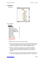
5. Example
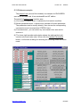
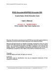
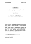
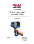
5.1 DOS example
The execution file MTEST.EXE is a command testing program, let you
can fully understand the action of every command. The source files include
MTEST.PRJ, MAIN.CPP, MSTEP2.h and MSTEP2.LIB. The file MAIN.CPP
provide examples of MSTEP2 command. If you have any question of
MSTEP2 command , you could trace the source file MAIN.CPP.
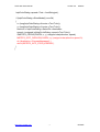
The pannel of MTEST.EXE has three area :
(1) Limit switch condition area : it indicate the limit switch condition.
(2) Motion parameter area : it shows every variable of motion parameter.
(3) Command area : you can select any command in this area and to
execute it.
You can press any key to stop X-axis and Y-axis.
There are three command MSTEP2_INTP_LONG_LINE( ),
MSTEP2_INTP_CIRCLE( ) and MSTEP2_INTP_ARC( ) that only can be
immediately stopped by /EMG switch.
2 Axes
Stepping
MotorMotor
Control
Card Card version
0.9 0.9
C.C.M.3/15/9
2 Axes
Stepping
Control
version
C.C.M.3/15/
Limit
Limit Switch
Switch
MSTEP2_SET_VAR
MSTEP2_HSP_MOVE
ORG1 ORG2 TP11 TPEF
TPEF
LS11 LS21 TP12
MSTEP2_SET_MODE
MSTEP2_CSP_MOVE
LS12 LS22 TP13
LS13 LS23 TP14 /TPG
MSTEP2_SET_DIRDEF
MSTEP2_SLOW_DOWN
LS14 LS24 TP21 TPG1
FFEF CPUS TP22 TPG2
MSTEP2_SET_SERVO_ON
MSTEP2_SLOW_STOP
FFFF XSTP
XSTP TP23
/EMG YSTP
YSTP TP24
MSTEP2_STOP_X
MSTEP2_LSP_PULSE_MOV
Motion
Motion Parameter
Parameter
DDA cycle
= 5
MSTEP2_STOP_Y
MSTEP2_HSP_PULSE_MOV
ACC/DEC
= 5
Low Speed
= 10
MSTEP2_STOP_ALL
MSTEP2_INTP_PULSE
High Speed
= 120
X output mode= CW/CCW
MSTEP2_RESET_SYSTEM
MSTEP2_INTP_LINE
Y output mode= CW/CCW
X direction = NORMAL
MSTEP2_LSP_ORG
MSTEP2_INTP_LONG_LIN
Y direction = NORMAL
X servo on
= ON
MSTEP2_HSP_ORG
MSTEP2_INTP_CIRCL
Y servo on
= ON
MSTEP2_HSD_ORG
MSTEP2_INTP_ARC
MSTEP2_LSP_MOVE
------ testing ----Press
any
key,
/EMG,
to
stop
!!
Press any key, /EMG, to stop !!
http://www.icpdas.com
-38-
ICPDAS
STEP-200 User Manual
Version 3.0
02/2001
5.2 Windows example
The project1.exe (source file included) is a example for ENCODER3
card and STEP200 card. It has windows95 and NT edition.
The pannel of project1.exe has four area :
(1) Limit switch condition area : it indicate the limit switch condition.
(2) Motion parameter area : it shows every variable of motion parameter.
The parameters can be modify directly, then choose the correponding
command to send command into STEP200 card.
(3) Command area : you can select any command in this area and to
execute it.
(4) The lower-right encoder sub-window shows the address(decimal),
counter value and index value. When click the Update Parameters
button, it will shows a dialog for selecting the counting mode and times
mode.
http://www.icpdas.com
-39-
ICPDAS