1
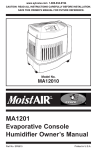
54-2221-01A_SPLM Manual 7.13_Layout 1 10/3/13 11:16 AM Page 1
SPLM
DIGITAL SOUND PRESSURE
LEVEL METER
I NSTRUCTION
Specifications are subject to change without notice.
© 2013 Bogen Communications, Inc.
M ANUAL
54-2221-01A 1307
54-2221-01A_SPLM Manual 7.13_Layout 1 10/3/13 11:16 AM Page 2
TABLE
O F
CO NTENTS
1. DESCRIPTION
Introduction ..............................................................1
Package Contents ...................................................1
Product Highlights....................................................1
Diagram/Features of the SPLM............................2, 3
LCD Display Callouts ...............................................4
Specifications...........................................................5
Calibrations ..............................................................6
Calendar Setting ......................................................6
2. OPERATING INSTRUCTIONS
Battery Installation ...................................................7
Level Range Selection..........................................7-9
Time Weighting Selection ......................................10
Frequency Weighting Selection .............................10
MAX Value Measurement ......................................11
Data Record ...........................................................11
Data Clear ..............................................................11
PC Connection.......................................................12
SoundLab Software Download/Installation ............12
3. IMPORTANT UNIT INFORMATION
Conditions of Usage ..............................................13
Limited Warranty....................................................13
54-2221-01A_SPLM Manual 7.13_Layout 1 10/3/13 11:16 AM Page 3
1. DESCRIPTION
Introduction:
The SPLM has been designed to meet the measurement requirements of
audio engineers, audio installers, noise quality control, health prevention
in various environments and all other noise measurement applications.
Package Contents:
The Bogen Digital Sound Pressure
Level Meter comes with the
following items:
• Sound Pressure Level Meter
• Windscreen
• USB Connecting Cable
• Signal Output Wire
• 1.5V Alkaline Batteries
• Carrying Case
• Instruction Manual
Product Highlights:
The SPLM was designed according to IEC 651 TYPE2 and ANSI S1.4
TYPE2 standards.
• Accuracy up to +/- 1.5 dB
• Measurement range is 30 to 130 dB
• Fast/Slow Time Weighting Selection
• Automatic Backlight
• Maximum Value Hold Function
• 10-Minute Auto Power Off
• A/C Frequency Weighting Selection
• AC and PWM Signal Output
• Calendar Function
• Data Record Function
• USB Connection to PC, provides data record downloading, real-time data
sampling analysis, and printing graph and data functions
1
54-2221-01A_SPLM Manual 7.13_Layout 1 10/3/13 11:16 AM Page 4
Diagram of the SPLM Unit
Digital Sound Level Meter
Range 30dB ~ 130dB
USB
MAX
CLOCK
AC
PWM
OUTPUT
A/C
CLEAR
DC 6V IN
LEVEL
F/S
RECORD
FRONT
VIEW
SIDE
VIEW
2
REAR
VIEW
54-2221-01A_SPLM Manual 7.13_Layout 1 10/3/13 11:16 AM Page 5
Features of the SPLM Unit
1. Windscreen- For use outdoors, prevents wind noise from affecting
the SPLM reading.
2. Condenser Microphone
3. LCD Display Screen
4.
5.
Power Button - Turns the SPLM Unit ON or OFF.
Level Button - Level range selection button & setting key.
6. Light Sensor
7.
MAX CLOCK Button - Maximum value hold and date/time
setting key.
8.
A/C CLEAR Button - Frequency weighting selection and recorded
data deletion key. Press down until CLA appears on display.
This will delete all the recorded data.
A: Weighting for general sound level measurements.
C: Weighting includes the low-frequency content of noise.
9.
F/S RECORD Button - Time weighting selection and data
recording key. Press down until RECORD appears on display.
This will enter data recording mode. Press again to exit this mode.
FAST (F): Displays instantaneous dB value.
SLOW (S): Displays average dB value (1 second).
10.
USB - USB jack.
11. PWM - Pulse Width Modulation output jack.
12. AC OUT - AC analog output jack.
13. DC 6V IN - 6V DC input jack.
14. Tripod Fixed Screw Mount
15. Calibration Potentiometer
16. Battery Compartment
(with cover removed)
3
54-2221-01A_SPLM Manual 7.13_Layout 1 10/3/13 11:16 AM Page 6
LCD Diagram & Features
1. Level Range Setting
10. A/C - Indicates Frequency
Weighting, A or C
2. DATE - Calendar Date
(year, month, day)
11. Reading Display
12. TIME - Calendar Clock
(hour, minute, second)
3. MAX - Maximum SPL Value
4. SPL - Sound Pressure Level
5.
13. Bar Graph
Low Battery Indicator
14.
6. USB - USB Connected
7. RECORD - Data Recording
Signals that the reading
is over the maximum range.
15. FAST / SLOW - Indicates Time
Weighting, Fast or Slow
8. FULL - Data Recording Full
16.
9. dB - Measurement Unit
4
Signals that the reading
is under the minimum range.
54-2221-01A_SPLM Manual 7.13_Layout 1 10/3/13 11:16 AM Page 7
Specifications
Measurement Range:
30 to 130 dB A, 30 to 130 dB C
Accuracy:
+/- 1.5 dB (reference sound pressure standard,
94 dB @ 1 kHz)
Frequency Response:
31.5 Hz to 8.5 kHz
Resolution:
0.1 dB
Measuring Level Ranges:
30 to 80, 50 to 100, 60 to 110, 80 to 130, 30 to 130
Dynamic Range:
50 dB/100 dB
Overload Indication:
OVER / UNDER
Frequency Weighting:
A and C
Digital Display:
4 Digits
Analog Bar Graph:
1 dB / bar (2 dB/bar for 30 to 130 range)
Sampling Rate:
0.05 seconds
AC Signal Output:
4 VRMS @ full bar graph, output impedance
600 ohms (3.5 mm connector)
PWM Signal Output:
Duty = 0.01 x dB Value x 100% (3.5 mm connector)
Cycle
3.3
Calendar Accuracy:
+/- 30 seconds per day
Data Storage Quantity:
4700 Points
Auto Power Off:
10 minutes of no activity
Microphone Type:
1/2- inch Condenser
Power Supply:
6V external or 4 AA alkaline battery
Dimensions:
2-3/4” W x 9-3/8” H x 1-3/8” D
Product Weight:
11 ounces (with batteries)
Battery Life:
10 hours continuous use (alkaline batteries)
5
54-2221-01A_SPLM Manual 7.13_Layout 1 10/3/13 11:16 AM Page 8
2. OPERATING INSTRUCTIONS
Battery Installation:
REAR VIEW
1. Remove the battery door and
insert 4 AA alkaline batteries
into the battery compartment.
BATTERIES
(4 AA)
2. Replace the battery door.
3. When the battery voltage drops
below the operating voltage,
a Low Battery Indicator icon
appears on the display. Replace
the batteries in the SPLM with
new batteries.
CA
L
SLIDE DOOR PANEL
DOWN TO OPEN
OP
EN
Calibration:
Please use typical 94 dB @ 1 kHz standard calibrator.
1. Slide open Battery Door to access
the Calibration Pot.
2. Setting on sound level meter:
A = Frequency weighting;
FAST = Time Weighting;
Level range is 60 dB to 110 dB.
3. Insert SPLM into calibrator.
4. Adjust Calibration Pot until the
display shows appropriate level
(See Figure 1).
CALIBRATOR
CALIBRATION
POT
A
dB
NOTE: The SPLM is calibrated prior to
shipment. The recommended calibration
cycle is one year.
CAL
BATTERIES
(4 AA)
Figure 1
6
54-2221-01A_SPLM Manual 7.13_Layout 1 10/3/13 11:16 AM Page 9
Calendar Setting:
Setting Date and Clock
Start with the SPLM Unit OFF.
1. While holding down the MAX
CLOCK Button, turn the unit
ON with the POWER button.
2. When the LCD screen flashes
the first digit of the calendar year
(see Figure 2), release the MAX
CLOCK button. Press the LEVEL
Figure 2
UP or DOWN button to adjust the
date. After adjusting the first digit, press the MAX CLOCK button to
adjust the next digit. Press MAX CLOCK to proceed through the date
digits. To adjust the time, continue to follow these steps.
3. When complete, press the MAX CLOCK button once again to exit the
calendar setting mode.
Level Range Selection:
1. Press the POWER button to
turn on the SPLM. The date will
be displayed on the LCD screen
for 2 seconds.
2. After 3 seconds, the screen
enters the default measurement
mode.
7
54-2221-01A_SPLM Manual 7.13_Layout 1 10/3/13 11:16 AM Page 10
Level Range Selection (contʼd):
30 – 130 (default)
3. Press the LEVEL UP or DOWN
button to select your desired
measuring range: 30 to 130
(default), 30 to 80, 50 to 100,
60 to 110, or 80 to 130. The LCD
screen displays will appear as
shown here:
30 – 80
50 – 100
60 – 110
80 – 130
8
54-2221-01A_SPLM Manual 7.13_Layout 1 10/3/13 11:16 AM Page 11
Level Range Selection (contʼd):
4. If the measuring range is higher than the actual SPL level, the LCD
screen will display the UNDER icon. (For example, if the Level set is 60
to 110 but the actual sound level is lower than 60 dB.) Press the LEVEL
DOWN button to lower the range until the UNDER icon disappears:
5. If the measuring range is lower than the actual SPL level, the LCD screen
will display the OVER icon. (For example, if the Level set is 30 to 80 but
the actual sound level is higher than 80 dB.) Press the LEVEL UP
button to raise the range until the OVER icon disappears:
9
54-2221-01A_SPLM Manual 7.13_Layout 1 10/3/13 11:16 AM Page 12
Time Weighting Selection:
1. The default time weighting is FAST
and the LCD screen display is:
2. Press the F/S RECORD button to
SLOW. The LCD screen display
changes to:
NOTE: Selecting SLOW will provide
a 1 second averaged reading.
Frequency Weighting
Selection:
1. The default frequency weighting is
A and the LCD screen display is:
2. Press the A/C CLEAR button to
change the frequency weighting to
C. The LCD display changes to:
A Weighting is used for general sound
level measurements. C Weighting includes
the low-frequency content of noise.
10
54-2221-01A_SPLM Manual 7.13_Layout 1 10/3/13 11:16 AM Page 13
MAX Value Measurement:
1. During the measurement process,
press the MAX CLOCK button to
hold the maximum reading. The
LCD displays as follows:
2. Press the MAX CLOCK button
again to exit the maximum value
measurement and return to the
normal measurement mode.
Data Record:
1. Press and hold the F/S RECORD
button until the Record interval is
displayed. Press LEVEL UP or
DOWN to adjust the record interval
(in secs).
NOTE: The Maximum record interval is
250 seconds.
2. Press the F/S RECORD to enter
data storage mode. Data will be
logged on the set interval. The
memory capacity is 4700 points.
After recording 4700 points, the
LCD display will indicate FULL.
If data record is completed or full,
press the F/S RECORD button
again to exit the record mode.
Then the flashing RECORD symbol will disappear.
NOTE: To review data, a PC with USB connection & SoundLab software is required.
Data Clear:
1. Press and hold the A/C CLEAR
button until the letters CLA appear
on the screen. Recorded data will
be deleted and the display will return to normal. 11
54-2221-01A_SPLM Manual 7.13_Layout 1 10/3/13 11:16 AM Page 14
PC Connection
Minimum requirements for
connection with a PC:
• CPU: Pentium 600 MHz or higher
• One USB interface port
• Resolution of 800 x 600 (True Color)
• 8 MB available memory
• 50 MB available disk memory
• Operating system:
Microsoft Windows XP/
Vista / Windows7
1. Insert one end of the USB cable
into the USB jack on the side of
the SPLM.
2. Plug the other end of the USB
cable into the USB interface port
on the PC.
NOTE: Once the connection is made, a USB icon appears on the LCD of the SPLM indicating
a successful connection. If the icon does not appear, the connection is not complete.
When connected to the PC, the PC supplies power to the SPLM (so the
AA batteries are not necessary and will not be used if in the unit when
connected to the PC). When the connection to the PC is ended, the SPLM
will turn off automatically as the power will no longer be supplies if no
batteries are in the SPLM.
Installing SoundLab Software
Visit the Bogen website (www.bogen.com)
to download the current version of the
SoundLab Software. Click the Setup.exe
program to enter the installation contact
interface.
12
54-2221-01A_SPLM Manual 7.13_Layout 1 10/3/13 11:16 AM Page 15
3. IMPORTANT UNIT INFORMATION
1. Do not store or use the SPLM in the following conditions:
• Near rain, water, or dust filled environments
• Air with high salt or sulfur content
• Air with other gases or chemical materials
• High temperature or direct sunlight
2. Do not impact the SPLM directly.
3. Do not use the SPLM in humid conditions.
Limited Warranty; Exclusion of Certain Damages
The Bogen SPLM Digital Sound Pressure Level Meter is warranted to be free from defects in material and workmanship for one (1) year from the date of sale to the original purchaser. Any part of the product covered by this
warranty that, with normal installation and use, becomes defective (as confirmed by Bogen upon inspection) during
the applicable warranty period, will be repaired or replaced by Bogen, at Bogen’s option, provided the product is
shipped insured and prepaid to: Bogen Factory Service Department, 50 Spring Street, Ramsey, NJ 07446, USA.
Repaired or replacement product will be returned to you freight prepaid. This warranty does not extend to any of
our products that have been subjected to abuse, misuse, improper storage, neglect, accident, improper installation
or have been modified or repaired or altered in any manner whatsoever, or where the serial number or date code
has been removed or defaced.
THE FOREGOING LIMITED WARRANTY IS BOGEN’S SOLE AND EXCLUSIVE WARRANTY AND THE PURCHASER’S SOLE AND EXCLUSIVE REMEDY. BOGEN MAKES NO OTHER WARRANTIES OF ANY KIND, EITHER EXPRESS OR IMPLIED, AND ALL IMPLIED WARRANTIES OF MERCHANTABILITY OR FITNESS FOR
A PARTICULAR PURPOSE ARE HEREBY DISCLAIMED AND EXCLUDED TO THE MAXIMUM EXTENT ALLOWABLE BY LAW. Bogen's liability arising out of the manufacture, sale or supplying of products or their use or
disposition, whether based upon warranty, contract, tort or otherwise, shall be limited to the price of the product.
IN NO EVENT SHALL BOGEN BE LIABLE FOR SPECIAL, INCIDENTAL OR CONSEQUENTIAL DAMAGES
(INCLUDING, BUT NOT LIMITED TO, LOSS OF PROFITS, LOSS OF DATA OR LOSS OF USE DAMAGES)
ARISING OUT OF THE MANUFACTURE, SALE OR SUPPLYING OF PRODUCTS, EVEN IF BOGEN HAS BEEN
ADVISED OF THE POSSIBILITY OF SUCH DAMAGES OR LOSSES. Some States do not allow the exclusion
or limitation of incidental or consequential damages, so the above limitation or exclusion may not apply to you.
This warranty gives you specific legal rights, and you may also have other rights which vary from State to State.
Products that are out of warranty will also be repaired by the Bogen Factory Service Department – same address
as above or call 201-934-8500. The parts and labor involved in these repairs are warranted for 90 days when repaired by the Bogen Factory Service Department. All shipping charges in addition to parts and labor charges will
be at the owner's expense. All returns require a Return Authorization number. For most efficient warranty or repair
service, please include a description of the failure.
12/2008
13
54-2221-01A_SPLM Manual 7.13_Layout 1 10/3/13 11:16 AM Page 16
50 Spring Street, Ramsey, NJ 07446, U.S.A.
Tel. 201-934-8500 • Fax: 201-934-9832
www.bogen.com