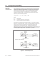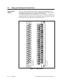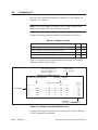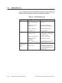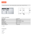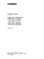
1
SIMATIC 505 Analog I/O Modules (PPX:505–6108A PPX:505–6108B PPX:505–6208A PPX:505–6208B) User Manual Order Number: PPX:505–8120–3 Manual Assembly Number: 2586546–0072 Third Edition ! DANGER DANGER indicates an imminently hazardous situation that, if not avoided, will result in death or serious injury. DANGER is limited to the most extreme situations. ! WARNING WARNING indicates a potentially hazardous situation that, if not avoided, could result in death or serious injury, and/or property damage. ! CAUTION CAUTION indicates a potentially hazardous situation that, if not avoided, could result in minor or moderate injury, and/or damage to property. CAUTION is also used for property-damage-only accidents. Copyright 1998 by Siemens Energy & Automation, Inc. All Rights Reserved — Printed in USA Reproduction, transmission, or use of this document or contents is not permitted without express consent of Siemens Energy & Automation, Inc. All rights, including rights created by patent grant or registration of a utility model or design, are reserved. Since Siemens Energy & Automation, Inc., does not possess full access to data concerning all of the uses and applications of customer’s products, we do not assume responsibility either for customer product design or for any infringements of patents or rights of others which may result from our assistance. MANUAL PUBLICATION HISTORY SIMATIC 505 Analog I/O Modules User Manual Order Manual Number: PPX:505–8120–3 Refer to this history in all correspondence and/or discussion about this manual. Event Date Description Original Issue Second Edition Third Edition 10/91 12/92 08/98 Original Issue (2591824–0001) Second Edition (2591824–0002) Third Edition (2591824–0003) LIST OF EFFECTIVE PAGES Pages Cover/Copyright History/Effective Pages iii — viii 1-1 — 1-10 2-1 — 2-14 3-1 — 3-9 A-1 B-1 — B-5 Registration Description Third Third Third Third Third Third Third Third Third Pages Description Contents Preface Chapter 1 Product Overview 1.1 Description . . . . . . . . . . . . . . . . . . . . . . . . . . . . . . . . . . . . . . . . . . . . . . . . . . . . . . . . . . . . . . . . . . . . . 1-2 1.2 Analog Input Operation . . . . . . . . . . . . . . . . . . . . . . . . . . . . . . . . . . . . . . . . . . . . . . . . . . . . . . . . . 1-4 Signal Translation . . . . . . . . . . . . . . . . . . . . . . . . . . . . . . . . . . . . . . . . . . . . . . . . . . . . . . . . . . . . . . . Analog Signal for PPX:505–6108A . . . . . . . . . . . . . . . . . . . . . . . . . . . . . . . . . . . . . . . . . . . . . . . . Analog Signal for PPX:505–6108B . . . . . . . . . . . . . . . . . . . . . . . . . . . . . . . . . . . . . . . . . . . . . . . . . Current or Voltage Input . . . . . . . . . . . . . . . . . . . . . . . . . . . . . . . . . . . . . . . . . . . . . . . . . . . . . . . . Choosing Resistors . . . . . . . . . . . . . . . . . . . . . . . . . . . . . . . . . . . . . . . . . . . . . . . . . . . . . . . . . . . . . . Calculating Digital Words for the PPX:505–6108A . . . . . . . . . . . . . . . . . . . . . . . . . . . . . . . . . . Calculating Digital Words for the PPX:505–6108B . . . . . . . . . . . . . . . . . . . . . . . . . . . . . . . . . . 1-4 1-4 1-5 1-6 1-6 1-7 1-7 1.3 Analog Output Operation . . . . . . . . . . . . . . . . . . . . . . . . . . . . . . . . . . . . . . . . . . . . . . . . . . . . . . . 1-8 1.4 Power Sources . . . . . . . . . . . . . . . . . . . . . . . . . . . . . . . . . . . . . . . . . . . . . . . . . . . . . . . . . . . . . . . . . . 1-10 Chapter 2 Installation 2.1 Wiring Guidelines . . . . . . . . . . . . . . . . . . . . . . . . . . . . . . . . . . . . . . . . . . . . . . . . . . . . . . . . . . . . . . . 2-2 2.2 Planning Analog Output Wiring . . . . . . . . . . . . . . . . . . . . . . . . . . . . . . . . . . . . . . . . . . . . . . . . . . 2-4 Signal Wire Carrying Current . . . . . . . . . . . . . . . . . . . . . . . . . . . . . . . . . . . . . . . . . . . . . . . . . . . . . Signal Wire Carrying Voltage . . . . . . . . . . . . . . . . . . . . . . . . . . . . . . . . . . . . . . . . . . . . . . . . . . . . 2-4 2-5 Wiring and Installing the Terminal Block . . . . . . . . . . . . . . . . . . . . . . . . . . . . . . . . . . . . . . . . . . 2-6 Terminal Block Options . . . . . . . . . . . . . . . . . . . . . . . . . . . . . . . . . . . . . . . . . . . . . . . . . . . . . . . . . . Wiring the Terminal Block . . . . . . . . . . . . . . . . . . . . . . . . . . . . . . . . . . . . . . . . . . . . . . . . . . . . . . . . Selecting Voltage or Current Inputs for the Analog Input Module . . . . . . . . . . . . . . . . . . 2-6 2-7 2-9 Inserting the Module . . . . . . . . . . . . . . . . . . . . . . . . . . . . . . . . . . . . . . . . . . . . . . . . . . . . . . . . . . . . 2-12 Apply Power . . . . . . . . . . . . . . . . . . . . . . . . . . . . . . . . . . . . . . . . . . . . . . . . . . . . . . . . . . . . . . . . . . . . 2-13 Configuring I/O . . . . . . . . . . . . . . . . . . . . . . . . . . . . . . . . . . . . . . . . . . . . . . . . . . . . . . . . . . . . . . . . . 2-14 2.3 2.4 2.5 Chapter 3 Troubleshooting and Maintenance 3.1 Status Indicator . . . . . . . . . . . . . . . . . . . . . . . . . . . . . . . . . . . . . . . . . . . . . . . . . . . . . . . . . . . . . . . . . 3-2 3.2 Replacing the Fuse . . . . . . . . . . . . . . . . . . . . . . . . . . . . . . . . . . . . . . . . . . . . . . . . . . . . . . . . . . . . . 3-3 3.3 Calibration Guidelines . . . . . . . . . . . . . . . . . . . . . . . . . . . . . . . . . . . . . . . . . . . . . . . . . . . . . . . . . . 3-4 3.4 Calibrating Analog Input Modules . . . . . . . . . . . . . . . . . . . . . . . . . . . . . . . . . . . . . . . . . . . . . . . 3-6 3.5 Calibrating Analog Output Modules . . . . . . . . . . . . . . . . . . . . . . . . . . . . . . . . . . . . . . . . . . . . . 3-8 Contents iii Appendix A Terminal Block Worksheet . . . . . . . . . . . . . . . . . . . . . . . . . . . . . . . . . A-1 Appendix B Specifications . . . . . . . . . . . . . . . . . . . . . . . . . . . . . . . . . . . . . . . . . . . B-1 iv Contents List of Figures 1-1 1-2 1-3 1-4 1-5 1-6 Series 505 Analog Modules (PPX–505–6108B and PPX–6208B) . . . . . . . . . . . . . . . . . . . . . . . . Output from the PPX:505–6108A Module to the Controller . . . . . . . . . . . . . . . . . . . . . . . . . . . Output from the PPX:505–6108B Module to the Controller . . . . . . . . . . . . . . . . . . . . . . . . . . . Effect of Voltage Input on the Module . . . . . . . . . . . . . . . . . . . . . . . . . . . . . . . . . . . . . . . . . . . . . Relationship of Update Time to Change in Signal Output . . . . . . . . . . . . . . . . . . . . . . . . . . . Output from Controller to Module . . . . . . . . . . . . . . . . . . . . . . . . . . . . . . . . . . . . . . . . . . . . . . . . . 1-3 1-4 1-5 1-5 1-8 1-9 2-1 Current Output Circuit . . . . . . . . . . . . . . . . . . . . . . . . . . . . . . . . . . . . . . . . . . . . . . . . . . . . . . . . . . . . 2-2 Terminal Blocks . . . . . . . . . . . . . . . . . . . . . . . . . . . . . . . . . . . . . . . . . . . . . . . . . . . . . . . . . . . . . . . . . . . 2-3 Wire Gauge and Stud Sizes . . . . . . . . . . . . . . . . . . . . . . . . . . . . . . . . . . . . . . . . . . . . . . . . . . . . . . . . 2-4 Pinouts for PPX:505–6108A, PPX:505–6108B, PPX:505–6208A, and PPX:505–6208B . . . . . . 2-5 Analog Input Module: Field Wiring for Current/Voltage . . . . . . . . . . . . . . . . . . . . . . . . . . . . . . 2-6 Analog Input Module: Field Wiring for 2-wire Transmitter . . . . . . . . . . . . . . . . . . . . . . . . . . . . . 2-7 Analog Input Module: Field Wiring for 4-wire Transmitter . . . . . . . . . . . . . . . . . . . . . . . . . . . . . 2-8 Analog Output Module: Typical 4-channel Connection . . . . . . . . . . . . . . . . . . . . . . . . . . . . . 2-9 Installing the Analog Module . . . . . . . . . . . . . . . . . . . . . . . . . . . . . . . . . . . . . . . . . . . . . . . . . . . . . . 2-10 Sample I/O Module Definition Chart . . . . . . . . . . . . . . . . . . . . . . . . . . . . . . . . . . . . . . . . . . . . . . . 2-4 2-6 2-7 2-8 2-9 2-10 2-10 2-11 2-12 2-14 3-1 Output Module Fuse Location and Replacement Value . . . . . . . . . . . . . . . . . . . . . . . . . . . . 3-2 Euro-extender Card Assembly for Analog Input . . . . . . . . . . . . . . . . . . . . . . . . . . . . . . . . . . . . . 3-3 Euro-extender Card Assembly for Analog Output . . . . . . . . . . . . . . . . . . . . . . . . . . . . . . . . . . . 3-3 3-6 3-8 Contents v List of Tables 1-1 Analog Input Module Power Cycling . . . . . . . . . . . . . . . . . . . . . . . . . . . . . . . . . . . . . . . . . . . . . . . 1-2 Analog Output Module Power Cycling . . . . . . . . . . . . . . . . . . . . . . . . . . . . . . . . . . . . . . . . . . . . . 1-10 1-10 2-1 Module I/O Values . . . . . . . . . . . . . . . . . . . . . . . . . . . . . . . . . . . . . . . . . . . . . . . . . . . . . . . . . . . . . . . . 2-14 3-1 Troubleshooting Chart . . . . . . . . . . . . . . . . . . . . . . . . . . . . . . . . . . . . . . . . . . . . . . . . . . . . . . . . . . . . . 3-2 B-1 B-2 B-3 B-4 B-5 B-1 B-2 B-3 B-4 B-5 vi Environmental Specifications: Analog Input and Output Modules . . . . . . . . . . . . . . . . . . . . Analog Input Module PPX:505–6108A Electrical Specifications . . . . . . . . . . . . . . . . . . . . . . . Analog Input Module PPX:505–6108B Electrical Specifications . . . . . . . . . . . . . . . . . . . . . . . . Analog Output Module PPX:505–6208A Electrical Specifications . . . . . . . . . . . . . . . . . . . . . Analog Output Module PPX:505–6208B Electrical Specifications . . . . . . . . . . . . . . . . . . . . . . Contents Preface Manual Content This manual contains instructions for installing, wiring, and calibrating the Analog Input Modules (PPX:505–6108A and PPX:505–6108B), and the Analog Output Modules (PPX:505–6208A and PPX:505–6208B). The modules operate with the Series 505 controller. The manual does not give the details of analog-to-digital conversion techniques. Familiarity with these techniques may be necessary in some applications. References Agency Approvals Refer to the manuals listed below for instructions on installing, programming, and troubleshooting your System 505 controller. • SIMATIC 505 System Manual (PPX:505–8201–x) • SIMATIC 505 Programming Reference Manual (PPX:505–8204–x) • SIMATIC 505 Softshop for Windows User Manual (PPX:SS505–8101–x) • SIMATIC 500/505 TISOFT Release 6.3 User Manual (PPX:TS505–8101–x) Series 505 Analog Input and Analog Output Modules meet standards of the following agencies: • Underwriters Laboratories: UL Listed (Industrial Control Equipment) • Canadian Standards Association: CSA Certified (Process Control Equipment) • Factory Mutual Approved; Class I, Div. 2 Hazardous Locations • CE Marking: Low Voltage Directive 73/23/EEC; Electromagnetic Compatibility Directive 89/336/EEC • Verband Deutscher Elektrotechniker (VDE) 0160 Electrical Equipment (Self-Compliance) Series 505 products have been developed with consideration of the draft standard of the International Electrotechnical Commission Committee proposed standard (IEC–65A/WG6) for programmable controllers (released as IEC 1131–2, Programmable Controllers, Part 2: Equipment Requirements and Tests, First Edition, 1992–09). Contact Siemens Energy & Automation, Inc., for information about regulatory agency approvals that have been obtained on Series 505 units. Series 505 Analog I/O Modules User Manual Preface vii Telephoning for Assistance viii Preface For technical assistance, contact your Siemens Energy & Automation, Inc. distributor. Series 505 Analog I/O Modules User Manual Chapter 1 Product Overview 1.1 Description . . . . . . . . . . . . . . . . . . . . . . . . . . . . . . . . . . . . . . . . . . . . . . . . . . . . . . . . . . . . . . . . . . . . . 1-2 1.2 Analog Input Operation . . . . . . . . . . . . . . . . . . . . . . . . . . . . . . . . . . . . . . . . . . . . . . . . . . . . . . . . . 1-4 Signal Translation . . . . . . . . . . . . . . . . . . . . . . . . . . . . . . . . . . . . . . . . . . . . . . . . . . . . . . . . . . . . . . . Analog Signal for PPX:505–6108A . . . . . . . . . . . . . . . . . . . . . . . . . . . . . . . . . . . . . . . . . . . . . . . . Analog Signal for PPX:505–6108B . . . . . . . . . . . . . . . . . . . . . . . . . . . . . . . . . . . . . . . . . . . . . . . . . Current or Voltage Input . . . . . . . . . . . . . . . . . . . . . . . . . . . . . . . . . . . . . . . . . . . . . . . . . . . . . . . . Choosing Resistors . . . . . . . . . . . . . . . . . . . . . . . . . . . . . . . . . . . . . . . . . . . . . . . . . . . . . . . . . . . . . . Calculating Digital Words for the PPX:505–6108A . . . . . . . . . . . . . . . . . . . . . . . . . . . . . . . . . . Calculating Digital Words for the PPX:505–6108B . . . . . . . . . . . . . . . . . . . . . . . . . . . . . . . . . . 1-4 1-4 1-5 1-6 1-6 1-7 1-7 1.3 Analog Output Operation . . . . . . . . . . . . . . . . . . . . . . . . . . . . . . . . . . . . . . . . . . . . . . . . . . . . . . . 1-8 1.4 Power Sources . . . . . . . . . . . . . . . . . . . . . . . . . . . . . . . . . . . . . . . . . . . . . . . . . . . . . . . . . . . . . . . . . . 1-10 Series 505 Analog I/O Modules User Manual Product Overview 1-1 1.1 Description The Series 505 Analog Input (PPX:505–6108A and PPX:505–6108B), and Output (PPX:505–6208A and PPX:505–6208B) Modules are single-wide versions of the Analog I/O Modules (PPX:505–6108 and PPX:505–6208), and can replace the double-wide models without any wiring changes. The Input Modules (PPX:505–6108A and PPX:505–6108B) offer the additional benefit of an optional ±10 V input range, and they do not require external user-supplied power. The Output Modules (PPX:505–6208A, and PPX:505–6208B), like the double-wide PPX:505–6208, require user-supplied 24 VDC power to maintain low power consumption from the base. The Series 505 Analog I/O Modules (Figure 1-1) connect the controller with devices which monitor or control pressure, position, flow, temperature, or speed using voltage or current signals. The input module translates an analog input signal from a monitoring device into an equivalent digital word and transmits that data to the controller for processing. The output module translates a digital word from the controller into an equivalent analog signal and transmits that data to an output device that controls pressure, position, flow, temperature, or speed. A Module Good LED on the front of each module indicates the status of the power, self-diagnostics, and the fuse (for the output module). Figure 1-1 shows the location of the Module Good LED indicator of the PPX:505–6108B and PPX:505–6208B. If the LED is on: • System and user power are good • Fuse is good • Module has passed self-diagnostics If the LED is off, one of the above has failed. See Chapter 3 for instructions on using the LED to troubleshoot. 1-2 Product Overview Series 505 Analog I/O Modules User Manual Backplane connector Bezel screw Module description Module good LED Terminal block Model number PPX:505–6208B Output Module PPX:505–6108B Input Module Figure 1-1 Series 505 Analog Modules (PPX–505–6108B and PPX–6208B) Series 505 Analog I/O Modules User Manual Product Overview 1-3 1.2 Analog Input Operation Signal Translation The Analog Input module operates asynchronously with the controller. That is, the controller and module do not update at the same time. Instead, the module translates all analog inputs in one module update and stores the translated words in buffer memory. When the controller I/O scan starts, it retrieves the words from the buffer memory of the module. Analog Signal for PPX:505–6108A The PPX:505–6108A analog signal is translated into a 12-bit digital word. Since the controller requires a 16-bit word for inputs, the 12-bit value from the converter is placed into a 16-bit word for transmittal to the controller. As shown in Figure 1-2, of the four bits not used for the converter magnitude, one is used to show the sign of the value, one is used to note overrange values, and the remaining two are not used and are set to zero. MSB 1 2 3 4 5 6 7 8 9 LSB 10 11 12 13 14 15 16 Digital word converted from analog input Sign bit 1 = negative 0 = positive Not used Set to zero Overrange if set to 1. Figure 1-2 Output from the PPX:505–6108A Module to the Controller 1-4 Product Overview Series 505 Analog I/O Modules User Manual Analog Signal for PPX:505–6108B The PPX:505–6108B analog signal is translated into a 13-bit digital word. Since the controller requires a 16-bit word for inputs, the 13-bit value from the converter is placed into a 16-bit word for transmittal to the controller. As shown in Figure 1-3, of the three bits not used for the converter magnitude, one is used to show the sign of the value, one is used to note overrange values, and the remaining one is not used and is set to zero. MSB 1 2 3 4 5 6 7 8 9 LSB 10 11 12 13 14 15 16 Digital word converted from analog input Sign bit 1 = negative 0 = positive Not used Set to zero Overrange if set to 1. Figure 1-3 Output from the PPX:505–6108B Module to the Controller An overrange condition arises from an excessive voltage input, causing the digital word to be in excess of ±32000. Figure 1-4 shows the effects of excessive voltage. Values in parentheses apply to the ±10 V range. 0V Below –30 V Module not protected Damage may occur –30 V to –5.00125 V (–10.0025 V) Overrange bit set to 1. Above 30 V Module not protected Damage may occur –5.00125 V to +5.00125 V (–10.00250 V to +10.00250 V) Accuracy within specifications 5.00125 V (+10.0025 V) to +30 V Overrange bit set to 1. Figure 1-4 Effect of Voltage Input on the Module Series 505 Analog I/O Modules User Manual Product Overview 1-5 Analog Input Operation (continued) Current or Voltage Input The analog input module has eight inputs. You can select each of the eight inputs to receive either voltage or current as the incoming analog signal. Since the inputs are single-ended, the source for a current signal must be a true current-sourcing transmitter, not a current-sinking transmitter. • For a voltage input, the incoming signal may range from –5 to +5 V, or from –10 to +10 V. The optional voltage input range of ±10 V is available via jumper selection on the circuit board. The voltage range selected applies to all eight input channels. Refer to Figure 3-2. • For a current input, the incoming signal may range from 0 to 20 mA. NOTE: The module is factory-calibrated and shipped configured for the ±5 V input range, which is required for current input using the internal sense resistors. If your application requires ±10 V, recalibrate the module with the ±10 V setting selected. Choosing Resistors The input module has eight (one per point) built-in, precision resistors (250 Ω, 0.1%). The resistor changes input current to voltage, which is what the module monitors internally. The built-in resistor allows a current range from 0 to 20 mA. You may use other external resistor values for other current ranges. If you install an external resistor, be sure that it meets the ±5 V input constraint and connects between Voltage In and Return for the selected channel. Follow proper safety guidelines when you install resistors. To determine the resistor needed, use the following equation. 1-6 Product Overview Series 505 Analog I/O Modules User Manual Calculating Digital Words for the PPX:505–6108A The PPX:505–6108A module has a resolution of 8 counts out of 32000. That is, the smallest unit into which the module divides a unipolar input is 1 part out of 4000. For a voltage input of 0 to +5 V, this division corresponds to a step of 1.25 mV. For a current input of 0 to 20 mA, a step of 5 µA can be resolved. Use the following equations to calculate the digital word which results from a particular voltage or current input. DigitalĄwordĄ(WX)Ą +Ą Input voltage Ą 5V DigitalĄwordĄ(WX)Ą +Ą Input current (mA) Ą 20 mA Ą 32000 Ą 32000 If the module is set for ±10 V input range, each step of eight counts corresponds to an input voltage change of 2.5 mV, and the digital word is defined as follows: DigitalĄwordĄ(WX)Ą +Ą Calculating Digital Words for the PPX:505–6108B Input voltage Ą 10 V Ą 32000 The PPX:505–6108B module has a resolution of 4 counts out of 32000. That is, the smallest unit into which the module divides a unipolar input is 1 part out of 8000. For a voltage input of 0 to +5 V, this division corresponds to a step of 625µV. For a current input of 0 to 20 mA, a step of 2.5 µA can be resolved. Use the following equations to calculate the digital word which results from a particular voltage or current input. DigitalĄwordĄ(WX)Ą +Ą Input voltage Ą 5V DigitalĄwordĄ(WX)Ą +Ą Input current (mA) Ą 20 mA Ą 32000 Ą 32000 If the module is set for ±10 V input range, each step of eight counts corresponds to an input voltage change of 1.25 mV, and the digital word is defined as follows: DigitalĄwordĄ(WX)Ą +Ą Series 505 Analog I/O Modules User Manual Input voltage Ą 10 V Ą 32000 Product Overview 1-7 1.3 Analog Output Operation The analog output module operates synchronously with the controller. Any change in the output signal is dependent on the update time of the module. Figure 1-5 shows this relationship. Output Level New Output Level t r – t o = Response Time See Appendix B t s – t r = Settling Time See Appendix B t f – t o = Update Time See Appendix B Output Level from (X–1) Update Time to (Begin Update X) t r ts tf (Begin Update X + 1) Figure 1-5 Relationship of Update Time to Change in Signal Output The analog output module has eight channels, providing simultaneous voltage and current, ranging from 0 to 10 V and from 0 to 20 mA. Note that the current output is a sourcing type. Therefore, any shorts in the output circuit cause the output current to bypass the field device in the circuit. The controller sends a 16-bit binary word to the module. Figure 1-6 shows the data word format. The digital value, which is translated into an analog output signal, occupies 12 of the 16 bits. The most significant bit (MSB) denotes the sign of a value. The remaining bits are unused. 1-8 Product Overview Series 505 Analog I/O Modules User Manual NOTE: Bit 1 (the sign bit) is used to check for a negative number sent to the output module. If this bit is set to 1, the output for the point is not updated, and the last positive output is repeated. MSB 1 2 3 4 5 6 7 8 9 LSB 10 11 12 13 14 15 16 Digital word to be converted Sign bit 1 = negative 0 = positive Not used. Set to 0. Figure 1-6 Output from Controller to Module The resolution of the module is 8 counts out of 32000, regardless of whether the signal is used as voltage or current. Therefore, the smallest step unit for voltage is 2.5 mV and for current is 5 µA. To calculate the digital word necessary to achieve a certain output voltage or current, use the following equations. DigitalĄwordĄ(WY)Ą +Ą Desired output voltage Ą 10 V DigitalĄwordĄ(WY)Ą +Ą Desired output current (mA) Ą 20 mA Series 505 Analog I/O Modules User Manual Ą 32000 Ą 32000 Product Overview 1-9 1.4 Power Sources The output module requires both user-supplied and base-supplied power. Table 1-1 shows the input module response at power-up and power-down. Table 1-1 Analog Input Module Power Cycling Base Power User Power Module Transition on Not applicable Module resumes converting and controller resumes reading from module Transition off Not applicable Module and controller power down. All input data cleared Table 1-2 shows the output module response at power up and power down. Table 1-2 Analog Output Module Power Cycling Base Power 1-10 Product Overview User Power Module On Transition off Off—module sets fail bit On Transition on Resumes prior state until next update Transition off On Freezes last value Transition on On Holds last value until next update Off Transition on Off Series 505 Analog I/O Modules User Manual Chapter 2 Installation 2.1 Wiring Guidelines . . . . . . . . . . . . . . . . . . . . . . . . . . . . . . . . . . . . . . . . . . . . . . . . . . . . . . . . . . . . . . . 2-2 2.2 Planning Analog Output Wiring . . . . . . . . . . . . . . . . . . . . . . . . . . . . . . . . . . . . . . . . . . . . . . . . . . 2-4 Signal Wire Carrying Current . . . . . . . . . . . . . . . . . . . . . . . . . . . . . . . . . . . . . . . . . . . . . . . . . . . . . Signal Wire Carrying Voltage . . . . . . . . . . . . . . . . . . . . . . . . . . . . . . . . . . . . . . . . . . . . . . . . . . . . 2-4 2-5 Wiring and Installing the Terminal Block . . . . . . . . . . . . . . . . . . . . . . . . . . . . . . . . . . . . . . . . . . 2-6 Terminal Block Options . . . . . . . . . . . . . . . . . . . . . . . . . . . . . . . . . . . . . . . . . . . . . . . . . . . . . . . . . . Wiring the Terminal Block . . . . . . . . . . . . . . . . . . . . . . . . . . . . . . . . . . . . . . . . . . . . . . . . . . . . . . . . Selecting Voltage or Current Inputs for the Analog Input Module . . . . . . . . . . . . . . . . . . 2-6 2-7 2-9 Inserting the Module . . . . . . . . . . . . . . . . . . . . . . . . . . . . . . . . . . . . . . . . . . . . . . . . . . . . . . . . . . . . 2-12 Apply Power . . . . . . . . . . . . . . . . . . . . . . . . . . . . . . . . . . . . . . . . . . . . . . . . . . . . . . . . . . . . . . . . . . . . 2-13 Configuring I/O . . . . . . . . . . . . . . . . . . . . . . . . . . . . . . . . . . . . . . . . . . . . . . . . . . . . . . . . . . . . . . . . . 2-14 2.3 2.4 2.5 Series 505 Analog I/O Modules User Manual Installation 2-1 2.1 Wiring Guidelines Wiring for these modules consists of wiring for the input or output signal and wiring user power for the output module. Keep the two types of wiring separate to prevent noise on the signal wiring. Wiring for the input or output signal should be shielded, twisted-pair cable (14–24 AWG or 0.18–1.5 mm2, either stranded or solid-type). ! WARNING Use wires suitable for at least 75°C. Signal wiring connected to this module must be rated at least 300 V. ! ATTENTION Employer des fils d’alimentation pour au moins 75°C. Le cablage de signalisation raccordé dans cette boîte doit convenir pour une tension nominale d’au moins 300 V. 2-2 Installation Series 505 Analog I/O Modules User Manual Follow these guidelines when you wire the module. • Use the shortest possible wires. • Avoid placing signal wires parallel to high-energy wires. If the two must meet, cross them at right angles. • Avoid placing wires on any vibrating surfaces. • Avoid bending the wire into sharp angles. • Use wireways for wire routing. Terminate shielding for the input cable at the source end of the signal. This means that the point of origin of the input signal wire should be the shield termination point. If more convenient, you can terminate the shield to earth ground at the module using the two lower screws on the user wiring connector. Do not tie the shield to earth ground at both ends of the wiring; this practice may cause ground currents that could induce noise. Terminate shielding for the output cable at the base, using the two lower screw terminals on the user wiring connector. Series 505 Analog I/O Modules User Manual Installation 2-3 2.2 Planning Analog Output Wiring Signal Wire Carrying Current Loop resistance for the output circuit is determined by the length and type of wire and the device series resistance. This section gives instructions for calculating the maximum length cable you can use. The circuit resistance must be in the range of 10–600 Ω. If you use a separate power supply of 10 V, the minimum resistance increases to 600 Ω, and the maximum resistance increases to 1000 Ω. To determine the resistance of a channel output loop, use the following equation. Ă +Ă (2Ă Ă Ă Ă )Ă )Ă where CL = cable length RFT = conductor resistance (Ω/unit length) TFL = sum of resistance for all field devices The result of this equation must be less than 600 Ω. If the result is greater than 600 Ω but less than 1000 Ω, insert a 10 V power supply into the loop to maintain the accuracy of the module, or change one of the other loop resistance factors. Any value over 1000 Ω prevents the module from operating accurately. Figure 2-1 shows a schematic for wiring an output loop with a resistance of less than 600 Ω. Also shown in Figure 2-1 is a schematic for adding a power supply to allow loop resistance up to 1000 Ω. Resistance: 10–600 Ohms User Power Module Field Device 0–20 mA SHLD RTN IOUT – + Load (Between 10 and 600 Ω) To Base Earth Ground Resistance: 600–1000 Ohms User Power Module 0–20 mA RTN 10 V SHLD Power Supply + – – IOUT + Field Device Load (Between 600 and 1000 Ω) To Base Earth Ground Figure 2-1 Current Output Circuit 2-4 Installation Series 505 Analog I/O Modules User Manual Signal Wire Carrying Voltage To help ensure accuracy within module specifications, consider the following in choosing wire that carries voltage: • Load imposed by the field device • Type and length of wire • Wiring practices The load imposed by a field device must be at least 5000 Ω. The maximum capacitance that can be driven by the output is 0.01 µ F. The maximum cable length is a function of cable capacitance. To determine the maximum distance for a given cable, obtain the nominal value of cable capacitance per unit length as given by the manufacturer. Use this value in the following equation. Maximum cable length = 0.01 µ F Nominal cable capacitance (per unit length) NOTE: Nominal capacitance is capacitance between conductors. However, if one conductor is connected to the shield via a grounded power supply, the nominal value roughly doubles. You can use the length and conductor resistance of the cable to find the fixed error appearing at the field device. To determine the fixed error, use the following equation. ƪ Ă +Ă 1Ă *Ă where R1 = CL = RFT = 1 ) (2 ƫĂ ) Ă 100 field load resistance cable length conductor resistance (Ω/unit length) Series 505 Analog I/O Modules User Manual Installation 2-5 2.3 Wiring and Installing the Terminal Block Figure 2-2 shows the two terminal block types that are available for use with the analog I/O modules. Connector PPX:2587705–8006 is shipped with the modules. However, you can order the other connector, PPX:2587705–8002, and wire it identically. If you are replacing double-wide analog modules with single-wide analog modules, you can simply install the new modules and attach the old, wired terminal blocks. PPX:2587705–8002 Order separately PPX:2587705–8006 Shipped with module Terminal Block Options Figure 2-2 Terminal Blocks 2-6 Installation Series 505 Analog I/O Modules User Manual Wiring the Terminal Block You can wire the terminal block before or after it is attached to the module. 1. Strip back the insulation on the wires 0.25′′ or 1.0 cm. Use a 14–24 AWG or 0.18–1.5 mm2 wire, either stranded or solid-type. You may attach a spade or a ring lug (amp 34141) to the end of the wire if allowed by the connector type. Refer to Figure 2-3. 2. Using the appropriate pinout as a wiring guide (Figure 2-4), start with the D terminals and loosen the terminal block screws. 3. Connect the end of the wire to the loosened terminal block screw, and tighten firmly. Once the Ds are completed, tighten the C terminals, and continue until the terminal block is completely wired. 4. Ensure that all wires have good connections. Without good connections, the module does not operate properly. Stud Size: #4 (2.5mm) Amp Part#: 321462. Use with connector PPX:2587705–8002. Stud Size: #4 (2.5mm) Amp Part#: 327891. Use with connector PPX:2587705–8002. Max. Width: 5.54 mm (0.218 in.) Max. Width: 4.62 mm (0.182 in.) Wire Gauge: 14–24 (both connectors) 1 cm (0.25 in.) Figure 2-3 Wire Gauge and Stud Sizes Series 505 Analog I/O Modules User Manual Installation 2-7 Wiring and Installing the Terminal Block (continued) Not used Not used 24 VDC+ 24 V common I5 in I1 in I5 out I1 out V5 in V1 in V5 out V1 out Return 5 Return 1 Return 5 Return 1 Not used Not used Not used Not used Not used Not used Not used Not used I6 in I2 in I6 out I2 out V6 in V2 in V6 out V2 out Return 6 Return 2 Return 6 Return 2 Not used Not used Not used Not used Not used Not used Not used Not used I7 in I3 in I7 out I3 out V7 in V3 in V7 out V3 out Return 7 Return 3 Return 7 Return 3 Not used Not used Not used Not used Not used Not used Not used Not used I8 in I4 in I8 out I4 out V8 in V4 in V8 out V4 out Return 8 Return 4 Return 8 Return 4 Chassis Chassis Analog Input Modules PPX:505–6108A, PPX:505–6108B Chassis Chassis Analog Output Module PPX:505–6208A, PPX:505–6208B Figure 2-4 Pinouts for PPX:505–6108A, PPX:505–6108B, PPX:505–6208A, and PPX:505–6208B 2-8 Installation Series 505 Analog I/O Modules User Manual Selecting Voltage or Current Inputs for the Analog Input Module The Analog Input Module has eight input channels. Each of the eight channels may be selected to receive either voltage or current as the incoming analog signal. See Figure 2-5. • To wire voltage input signals, wire the input signal directly to the voltage input point. • To wire current input signals, you must jumper the voltage input point to the current input point for that channel. A2 Shield Channel 1 Input Current 250 Ω Internal Resistor jumper A1 Field Device A3 Return Shield To Earth Ground B2 Shield Channel 2 Input Voltage 250 Ω Internal Resistor B1 Return Field Device B3 Shield To Earth Ground Figure 2-5 Analog Input Module: Field Wiring for Current/Voltage Series 505 Analog I/O Modules User Manual Installation 2-9 Wiring and Installing the Terminal Block (continued) Figure 2-6 through Figure 2-8 show typical connections for analog input and analog output modules. Figure 2-6 and Figure 2-7 show Channel 1 of the analog input module configured for current and wired to a transmitter. Channel Input A2 250 Ω Internal Resistor jumper – A1 Field Device Power Supply – + Return + A3 Shield To Earth Ground Figure 2-6 Analog Input Module: Field Wiring for 2-wire Transmitter Channel Input A2 250 Ω Internal Resistor jumper + A1 Field Device Return User Power – A3 Shield To Earth Ground Figure 2-7 Analog Input Module: Field Wiring for 4-wire Transmitter In the analog output module, output voltage and current are provided simultaneously. As shown in Figure 2-8, you can wire each channel for current, voltage, or both. 2-10 Installation Series 505 Analog I/O Modules User Manual Terminal Block AC +– 24 VDC User Power AR D/A Converter Current Driver CH 1* Voltage Driver A5 A1 A6 Field Device A2 A7 A3 A8 A4 GND Shield at Base (Use on all Signal Lines) BC BR B5 D/A Converter Current Driver B1 CH 2* Voltage Driver B2 B6 B7 B3 B8 Field Devices B4 CC CR C5 D/A Converter Current Driver C1 CH 3* Voltage Driver C2 C6 C7 C3 C8 Field Device C4 DC DR D5 D/A Converter Current Driver D1 CH 4* Voltage Driver D2 D6 D7 D3 D8 Field Devices D4 Module Side Field Side *D/A converter for each channel drives current driver and voltage driver simultaneously. Figure 2-8 Analog Output Module: Typical 4-channel Connection Series 505 Analog I/O Modules User Manual Installation 2-11 2.4 Inserting the Module These analog I/O modules are single-wide. You can install either module in any unused I/O slot. However, avoid installing the modules next to high-energy switching modules or other potential sources of electromagnetic interference (EMI). Install the module in the same manner as any other Series 505 I/O module. To minimize the possibility of electrostatic damage to the components, do not touch the printed circuit board while you are inserting the module. Refer to Figure 2-9. ! WARNING To minimize the risk of personal injury or property damage, disable all power to the system before installing or removing I/O modules. Minimum torque: 2.6 in-lb (0.3N-m) Maximum torque: 4.12 in-lb (0.6N-m) Terminal block Figure 2-9 Installing the Analog Module 2-12 Installation Series 505 Analog I/O Modules User Manual Apply Power Apply power only to the base. Configure the I/O. See Section 2.5 on configuring the I/O. Now that the terminal block is installed and the module is configured, restore all user-supplied power to the base. NOTE: If more than one module is to be installed, do not restore power until all modules have been installed. If no problems are detected when power is supplied to the module, the status indicator on the front of the module lights. If the status indicator is not on or goes out during operation, the module has detected a failure. To correct the failure, refer to Chapter 3 on troubleshooting. Series 505 Analog I/O Modules User Manual Installation 2-13 2.5 Configuring I/O After you have inserted the module into the base, you must register the module in PLC memory. NOTE: If you do not register the module, the PLC logs a nonfatal error; however, the module LED status indicator remains on. Configure the analog modules as 8-point word as shown in Table 2-1. Table 2-1 Module I/O Values Module WX WY PPX:505–6108-A 8-channel analog input module 08 00 PPX:505–6208-A 8-channel analog output module 00 08 PPX:505–6108-B 8-channel analog input module 08 00 PPX:505–6208-B 8-channel analog output module 00 08 Figure 2-10 shows the typical screen used when configuring I/O (base 0, modules installed in slots 1 and 2). I/O Address The module is logged in as eight words (WX for inputs and WY for outputs) I/O MODULE DEFINITION FOR : I/O Slot Slot Number Base Number Displays number of the current base. CHANNEL 1 BASE 00 Number of Bit and Word I/O Special Address X Y WX WY Function 1 ..... 0001 ..... 00 .. 00 .. 08 .. 00 ....... No 2 ..... 0009 ..... 00 .. 00 .. 00 .. 08 ....... No 3 ..... 0000 ..... 00 .. 00 .. 00 .. 00 ....... No 4 ..... 0000 ..... 00 .. 00 .. 00 .. 00 ....... No SF Module The default for this definition is no. Figure 2-10 Sample I/O Module Definition Chart For more information on configuring I/O, refer to your SIMATIC 500/505 TISOFT Release 6.3 User Manual. 2-14 Installation Series 505 Analog I/O Modules User Manual Chapter 3 Troubleshooting and Maintenance 3.1 Status Indicator . . . . . . . . . . . . . . . . . . . . . . . . . . . . . . . . . . . . . . . . . . . . . . . . . . . . . . . . . . . . . . . . . 3-2 3.2 Replacing the Fuse . . . . . . . . . . . . . . . . . . . . . . . . . . . . . . . . . . . . . . . . . . . . . . . . . . . . . . . . . . . . . 3-3 3.3 Calibration Guidelines . . . . . . . . . . . . . . . . . . . . . . . . . . . . . . . . . . . . . . . . . . . . . . . . . . . . . . . . . . 3-4 3.4 Calibrating Analog Input Modules . . . . . . . . . . . . . . . . . . . . . . . . . . . . . . . . . . . . . . . . . . . . . . . 3-6 3.5 Calibrating Analog Output Modules . . . . . . . . . . . . . . . . . . . . . . . . . . . . . . . . . . . . . . . . . . . . . 3-8 Series 505 Analog I/O Modules User Manual Troubleshooting and Maintenance 3-1 3.1 Status Indicator The LED status indicator and the programming device indicate whether the module is operating correctly. Table 3-1 lists symptoms, possible causes, and corrective actions to take if the module is not operating correctly. Table 3-1 Troubleshooting Chart Symptom LED is not on Incorrect readings CPU nonfatal error because of module 3-2 Troubleshooting and Maintenance Probable Cause Corrective Action Not receiving user power—output module only Check power supply and connections Blown fuse—output module only Check for overvoltage or reversed polarity; replace fuse Self-diagnostics fail Return module for repair Base power is off Turn base power on Connections wrong Trace wiring connections Signal wire noise Use shielded wire and separate from power wiring Module not configured Check I/O configuration Module incorrectly calibrated Recalibrate the module Signal source error—input module only Verify that signal source levels are in range (Figure 1-4) Module configured wrong Reconfigure the module Module failed Check items under LED is not on; if the actions listed do not correct the problem, return the module for repair Series 505 Analog I/O Modules User Manual 3.2 Replacing the Fuse Figure 3-1 shows the location of the output module fuse. Replace it with the fuse shown. 0.5 A 125/250 V Fast-acting 5 × 20 mm San-O Ind. Corp MT4 or Equivalent PPX:2587679–8009 Fuse Figure 3-1 Output Module Fuse Location and Replacement Value Use the following procedure to replace the fuse. ! WARNING To minimize the risk of personal injury or property damage, disable all power to the module before replacing a fuse. 1. If the wires are too short for you to pull the module out to reach the fuse, disconnect the terminal block from the module. 2. Remove the module from the base. 3. Replace the blown fuse. 4. Insert the module into the base. 5. Connect the terminal block (if necessary). 6. Power up the system. If you cannot correct the problem, contact your Siemens Energy & Automation, Inc. distributor for technical assistance. Series 505 Analog I/O Modules User Manual Troubleshooting and Maintenance 3-3 3.3 Calibration Guidelines The modules are calibrated during manufacture and should not need to be calibrated again to operate properly; however, a maintenance schedule to check accuracy every six to twelve months is recommended. If the accuracy is not within specified tolerance at 25°C, recalibrate the module. You must calibrate the module with the CPU in program mode, not in RUN mode. Calibrate the module with or without a Euro-extender card (Euroboard) using the procedures outlined in the following sections. 3-4 Troubleshooting and Maintenance Series 505 Analog I/O Modules User Manual ! CAUTION To help avoid potential damage to equipment, use a non-metallic screwdriver to calibrate the module. Do not use a metallic screwdriver. ! WARNING To minimize the risk of personal injury or property damage, do not touch the printed circuit board during the calibration procedure while the system is powered up. Series 505 Analog I/O Modules User Manual Troubleshooting and Maintenance 3-5 3.4 Calibrating Analog Input Modules To calibrate the input module, follow this procedure. 1. Disable system and user power. 2. Disconnect the field wiring. 3. If you are using a Euro-extender card (Euroboard): Remove the module from the base. Insert the extender card into the I/O slot that the module occupied. You may use a Schroff, Inc. Test adapter board. Insert the module into the extender card (Figure 3-2). This provides access to the calibration potentiometer and input range select jumper. Calibration Potentiometer Series 505 Base Analog Input Module Input range jumper ±5 V ±10 V Euro-extender Card Figure 3-2 Euro-extender Card Assembly for Analog Input If you are not using a Euro-extender card: Remove all I/O modules from the base. Select voltage input range as shown in Figure 3-2. Move the analog input module to the far left (I/O slot 1) to allow maximum space to reach and adjust the potentiometer. 4. Power up the system and allow the module to reach its operating temperature (usually about 30 minutes, if cold). 5. Connect a programming device to the controller. If you are not using a Euro-extender card, configure the analog input module in slot 1. 3-6 Troubleshooting and Maintenance Series 505 Analog I/O Modules User Manual 6. Prompt the programming device to display the module points and their associated values. 7. Send +5.000 V to all input points (+10.000 V with the ±10 V input range). 8. Locate the calibration potentiometer on the circuit board (Figure 3-2). Turn the screw with a non-metallic screwdriver until the programming screen shows all addresses at an average of +32000. 9. Send –5.000 V to all input points (–10.000 V with the ±10 V input range). 10. Turn the screw on the calibration potentiometer until all the addresses read an average of –32000. 11. Input +5.000 V to all channels (+10.000 V with the ±10 V input range). 12. Verify that all addresses read the value shown below for your module. If not, return to step 9 and ensure that the calibration voltage source is accurate to three decimal places. For the PPX:505–6108A and PPX:505–6208A, verify that all addresses read +32000 +129/–128. For the PPX:505–6108B and PPX:505–6208B, verify that all addresses read +32000 +81/–80 . 13. Disable all power to the system. 14. If you are using a Euro-extender card: Remove it and insert the module into the I/O slots. Connect the field wiring. If you are not using a Euro-extender card: Replace all I/O modules and the analog module in the proper slots. Reconnect terminal block wiring. Reconfigure the WX input point for the analog input module. Reconfigure slot 1 to its original state. 15. Power up the system. Series 505 Analog I/O Modules User Manual Troubleshooting and Maintenance 3-7 3.5 Calibrating Analog Output Modules To calibrate the output module, follow this procedure. 1. Disable system and user power. 2. Disconnect all loads and field wiring (except user power). 3. If you are using a Euro-extender card (Euroboard): Remove the module from the base. Insert the extender card into the I/O slot that the module occupied. You may use a Schroff, Inc. Test adapter board. Insert the module into the extender card (Figure 3-3). This provides access to the calibration potentiometer. Analog Output Module Series 505 Base Euro-extender Card Calibration Potentiometer Figure 3-3 Euro-extender Card Assembly for Analog Output If you are not using a Euro-extender card: Remove all I/O modules from the base. Move the analog output module to the far left (I/O slot 1) to allow maximum space to reach and adjust the potentiometer. 3-8 4. Power up the system and allow the module to reach its operating temperature (usually about 30 minutes, if cold). 5. Connect a programming device to the controller. 6. If you are not using a Euro-extender card, configure the analog output module in slot 1. 7. Connect a 5.1k-Ω ± 5% load to the voltage outputs and a 100-Ω ± 5% load to the current outputs. 8. Write 32000 to all channels. Troubleshooting and Maintenance Series 505 Analog I/O Modules User Manual 9. Measure all voltage and current channels. Using the current outputs, calculate the mean of the output value, then find the channel whose output is closest to this calculated value. 10. Locate the calibration potentiometer on the circuit board (Figure 3-3). Using the channel which has an output closest to the mean output value, adjust to 20.000 mA at 25° C by using the calibration potentiometer. 11. Check that voltage outputs on channels are 10.000 V ±50 mV, and that the current output of each channel is 20.00 mA ±0.1 mA. If not, return to Step 7. Ensure that the calibration loads are connected properly. The calibration procedure is complete at this point. 12. Disable all power to the system. 13. If you are using a Euro-extender card: Remove it and insert the module into the I/O slots. Connect all loads and field wiring to the module. If you are not using a Euro-extender card: Replace all I/O modules and the analog module in the proper slots. Reconnect terminal block wiring. Reconfigure the WY output point for the analog output module. Reconfigure slot 1 to its original state. 14. Power up the system. Series 505 Analog I/O Modules User Manual Troubleshooting and Maintenance 3-9 Appendix A Terminal Block Worksheet Series 505 Analog I/O Modules User Manual Terminal Block Worksheet A-1 Appendix B Specifications Table B-1 Environmental Specifications: Analog Input and Output Modules Minimum torque for bezel screws 2.6 in-lb (0.3N-m) Maximum torque for bezel screws 4.12 in-lb (0.6N-m) Operating temperature 0 to 60° C (32 to 140° F) Storage temperature –40 to +70° C (–40 to 158° F) Relative humidity 5% to 95% noncondensing Pollution degree 2, IEC 664, 664A Vibration Sinusoidal IEC 68-2-6, Test Fc 0.15 mm peak-to-peak, 10–57 Hz; 1.0 g, 57–150Hz Random IEC 68-2-34, Test Fdc, equivalent to NAVMAT P–9492 0.04 g2/Hz, 80–350 Hz Electrostatic discharge IEC 801, Part 2, Level 4, (15k V) Shock IEC 68-2-27; Test Ea Noise immunity, conducted on Series 505 power supply and output module user power supply IEC 801, Part 4, Level 3 IEC255–4 Appendix E EEC 4517/79 Com(78) 766 Final Part 4 MIL STD 461B CS01, CS02 and CS06 Noise immunity, radiated IEC 801, Part 3, Level 3, MIL STD 461B RS01 and RS02 Isolation, field to controller 1500 Vrms Corrosion protection All parts of corrosion-resistant material or plated or painted as corrosion protection NOTE: Variation in readings of up to 100% of full scale may occur during electromagnetic interference (EMI). Series 505 Analog I/O Modules User Manual Specifications B-1 Table B-2 Analog Input Module PPX:505–6108A Electrical Specifications Number of input points 8, single-ended Module width Single-wide Signal range (selected voltage range applies to all channels) –5 V to +5 V and 0 to 20 mA, or –10 V to +10 V Voltage accuracy (±) 0.82% of full scale over operating range (±) 0.5% of full scale at 25°C Current accuracy (±) 1.25% of full scale over operating range (±) 0.7% of full scale at 25°C Temperature coefficient Voltage input Current input 58 ppm/°C 83 ppm/°C Repeatability (±) 0.1% of full scale over operating range Resolution (input) 12 bits plus sign, 1.25 mV or 5 µA (±5 V range) Analog-to-digital conversion 12 bits plus sign Conversion method Dual slope integration Input system conversion time delay 330 ms max Update time 250 ms max (for all channels) Sample repetition time 250 ms max Input filter delay time 75 ms typical DC input resistance 1M Ω min with ±5 V range selected 500k Ω min with ±10 V range selected Input protection Voltage Current Overvoltage to ±30 VDC Overcurrent to 30 mA Type of protection clamp diodes, optical isolation Module power from base 4 W max, 2.5 W typical User power requirements None Input signal wiring Shielded, twisted-pair cable (14–24 AWG or 0.18–1.5 mm2, stranded or solid) B-2 Specifications Series 505 Analog I/O Modules User Manual Table B-3 Analog Input Module PPX:505–6108B Electrical Specifications Number of input points 8, single-ended Module width Single-wide Signal range (selected voltage range applies to all channels) –5 V to +5 V and 0 to 20 mA, or –10 V to +10 V Voltage accuracy (±) 0.41% of full scale over operating range (±) 0.25% of full scale at 25°C Current accuracy (±) 0.63% of full scale over operating range (±) 0.35% of full scale at 25°C Temperature coefficient Voltage input Current input 50 ppm/°C typical 80 ppm/°C typical Repeatability (±) 0.1% of full scale over operating range Resolution (input) 13 bits plus sign, 0.625 mV or 2.5 µA (±5 V range) Analog-to-digital conversion 14 bits Conversion method Successive approximation Sample repetition time 25 ms max Input filter delay time 75 ms typical DC input resistance 1M Ω min Input protection Voltage Current Overvoltage to ±30 VDC Overcurrent to 30 mA Type of protection clamp diodes, optical isolation Module power from base 4 W max, 1.1 W typical User power requirements None Input signal wiring Shielded, twisted-pair cable (14–24 AWG or 0.18–1.5 mm2, stranded or solid) Series 505 Analog I/O Modules User Manual Specifications B-3 Table B-4 Analog Output Module PPX:505–6208A Electrical Specifications Output channels 8, single-ended, simultaneous voltage and current Module width Single-wide Signal range 0 to 10 VDC, 0 to 20 mA Voltage accuracy (±)1.45% of full scale over full temp. range (±)0.5% of full scale at 25°C Current accuracy (±)1.83% of full scale over full temp.range (±)0.5% of full scale at 25°C Temperature coefficient Voltage output Current output 136 ppm/°C 204 ppm/°C Digital-to-analog conversion 12 bits Resolution (output) 12 bits, 2.5 mV, 5 µA Update time 29 ms (min), controller scan time + 56 ms (max) Module response time 27 ms (min), 54 ms (max) Settling time Current: 2.0 ms (max); Voltage: 0.2 ms (max) Overshoot 50 mV typical Load resistance Voltage Current 5000 Ω min; no max 10 Ω min; 600 Ω max (600 Ω min, 1000 Ω max if extra 10-V power supply present in circuit) Capacitance load (voltage outputs) 100 pF max Inductive load (current outputs) 1.0 mH max Module power from base 2.0 W max, 1.0 W typical User power supply 20 to 28 VDC at 0.5 A with maximum ripple ±0.4 VDC, UL Class 2 power supply Power supply protection Overvoltage to 30 VDC, reverse voltage protected Output signal wiring Shielded, twisted-pair cable (14–24 AWG or 0.18–1.5 mm2, stranded or solid) B-4 Specifications Series 505 Analog I/O Modules User Manual Table B-5 Analog Output Module PPX:505–6208B Electrical Specifications Output channels 8, single-ended, simultaneous voltage and current Module width Single-wide Signal range 0 to 10 VDC, 0 to 20 mA Voltage accuracy (±)1.45% of full scale over full temp. range (±)0.5% of full scale at 25°C Current accuracy (±)1.83% of full scale over full temp.range (±)0.5% of full scale at 25°C Temperature coefficient Voltage output Current output 50 ppm/°C typical 100 ppm/°C typical Digital-to-analog conversion 12 bits Resolution (output) 12 bits, 2.5 mV, 5 µA Module response time 10 ms max Settling time Current: 2.0 ms (max); Voltage: 0.2 ms (max) Overshoot 50 mV typical Load resistance Voltage Current 5000 Ω min; no max 10 Ω min; 600 Ω max (600 Ω min, 1000 Ω max if extra 10-V power supply present in circuit) Capacitance load (voltage outputs) 0.01 µF max Inductive load (current outputs) 1.0 mH max Module power from base 2.0 W max, 1.0 W typical User power supply 20 to 28 VDC at 0.5 A with maximum ripple ±0.4 VDC, UL Class 2 power supply Power supply protection Overvoltage to 30 VDC, reverse voltage protected Output signal wiring Shielded, twisted-pair cable (14–24 AWG or 0.18–1.5 mm2, stranded or solid) Series 505 Analog I/O Modules User Manual Specifications B-5 B-6 Specifications Series 505 Analog I/O Modules User Manual Customer Registration We would like to know what you think about our user manuals so that we can serve you better. How would you rate the quality of our manuals? Excellent Good Fair Poor Accuracy Organization Clarity Completeness Overall design Size Index Would you be interested in giving us more detailed comments about our manuals? Yes! Please send me a questionnaire. No. Thanks anyway. Your Name: Title: Telephone Number: ( ) Company Name: Company Address: Manual Name: SIMATIC TI505 Analog I/O Modules User Manual Edition: Third Manual Assembly Number: 2586546-0072 Date: 08/98 Order Number: PPX:505–8120–3 FOLD NO POSTAGE NECESSARY IF MAILED IN THE UNITED STATES BUSINESS REPLY MAIL FIRST CLASS PERMIT NO.3 JOHNSON CITY, TN POSTAGE WILL BE PAID BY ADDRESSEE SIEMENS INDUSTRIAL AUTOMATION, INC. 3000 BILL GARLAND RD. P.O. BOX 1255 JOHNSON CITY TN 37605–1255 ATTN: Technical Communications M/S 3519 FOLD $ #$%# %# # " !$ ! # %# #$ " !$ !#( ! &%" %"! ! $ #$%# %# # " !#'#%#$ "#%"#$