1
AUTOMATIC
SEQUENTIAL VIDEO
SWITCHER
Ramsey Electronics Model No.
AVS10
Don’t miss a beat; watch 4 cameras on one monitor! Perfect for
multiple video camera installation, stores, household
surveillance systems, and more!
•
Automatic sequential switching of up to 4 separate video sources
•
Perfect for security cameras and baby monitors
•
Enable or disable video sources with the flick of a switch
•
Manual “hold” selection of any source
•
Variable front panel timing control
•
Easy one evening assembly
•
Add our matching case and knob set for a pro look
AVS10 – 1
RAMSEY TRANSMITTER KITS
• FM100B Professional FM Stereo Transmitter
• FM25B Synthesized Stereo Transmitter
• AM1, AM25 AM Transmitters
• TV6 Television Transmitter
RAMSEY RECEIVER KITS
• FR1 FM Broadcast Receiver
• AR1 Aircraft Band Receiver
• SR2 Shortwave Receiver
• AA7 Active Antenna
• SC1 Shortwave Converter
RAMSEY HOBBY KITS
• SG7 Personal Speed Radar
• SS70A Speech Scrambler
• ECG1 Heart Monitor
• WCT20 Wizard Cable Tracer
• PG13 Plasma Generator
• LABC1 Lead Acid Battery Charger
RAMSEY AMATEUR RADIO KITS
• DDF1 Doppler Direction Finder Kit
• HR Series HF All Mode Receivers
• QRP Series HF CW Transmitters
• CW7 CW Keyer
• CPO3 Code Practice Oscillator
• QRP Power Amplifiers
RAMSEY MINI-KITS
Many other kits are available for hobby, school, Scouts and just plain FUN. New
kits are always under development. Write or call for our free Ramsey catalog.
AUTOMATIC VIDEO SWITCHER KIT INSTRUCTION MANUAL
Ramsey Electronics publication No. MAVS10 Revision 2.2
First printing: January 2001
COPYRIGHT 2001 by Ramsey Electronics, Inc. 590 Fishers Station Drive, Victor, New York
14564. All rights reserved. No portion of this publication may be copied or duplicated without the
written permission of Ramsey Electronics, Inc. Printed in the United States of America.
AVS10 – 2
Ramsey Publication No. MAVS10
Manual Price Only $5.00
INSTRUCTION MANUAL FOR
AUTOMATIC
SEQUENTIAL VIDEO
SWITCHER
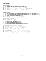
TABLE OF CONTENTS
Introduction ................................... 4
Circuit Description ......................... 4
Block Diagram................................ 5
Parts List ........................................ 6
Parts Layout Diagram .................... 7
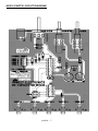
Schematic diagram ....................... 8
Assembly instructions ................. 10
Initial Testing ............................... 13
Troubleshooting ........................... 13
Ramsey Warranty ........................ 15
RAMSEY ELECTRONICS, INC.
590 Fishers Station Drive
Victor, New York 14564
Phone (585) 924-4560
Fax (585) 924-4555
www.ramseyelectronics.com
AVS10 – 3
INTRODUCTION
In today’s world there are many situations that require monitoring, but no one
can be in four places at once. Now, with the AVS10, you have the opportunity
to see four different locations and keep an eye on your precious property.
The front doorbell is ringing, the baby is napping, one of your children is
playing with friends on the backyard trampoline and another is shooting
hoops in the driveway. Of course, you need to be in the kitchen or home
office and even with the proverbial parental “eyes in the back of your head”
you can’t possibly keep an eye on everyone! With the AVS10 and four
inexpensive video cameras you can do the impossible. And if you see a
situation that requires a longer look, simply press the SCAN/STOP button
and take as long as you need to assure you that all is well. The AVS10 is the
perfect baby/playroom monitor, allowing you the freedom to monitor the
action without having to be physically present. You can keep an eye on your
shed, boat or other outdoor property as well. We believe you’ll find dozens of
applications for this useful kit and at a fraction of the cost of commercial
video switchers!
.
CIRCUIT DESCRIPTION
The AVS10 takes advantage of the Motorola 68HC908 family’s power, thus
eliminating the need for bulky logic gates to control the switching of up to 4
input video signals. By periodically testing the state of each enable switch
(S1:1 – S1:4), the microcontroller (U1) will activate the respective video
control switch (U2:A – D) enabling each individual video feed.
The 68HRC908JK1 microcontroller uses an RC (Resistor & Capacitor)
network to set up the controlling frequency. Resistors R1, R2 (variable front
panel potentiometer), and R3 along with the fixed value capacitor C1 make
up the timing circuit for the system. The front panel speed control (R2,
variable potentiometer) lets us vary the control frequency from about 2MHz to
8MHz. This is how the scan rate between the input video signals is controlled
giving the user full range from approximately 1 to 5 second switching times.
The SCAN/STOP button (S3) lets the user stop on any active video channel
and hold that particular feed for indefinite viewing. The active low enabling of
the IRQ line (U1 pin 1) from S3, the SCAN/STOP button, gives easy access
to the end user for other remote scan stop triggering in custom applications.
Using the CD4066 Bilateral Switch (U2) as the actual video control switcher
lends itself nicely to this application. The quad bilateral switch was intended
for the transmission or multiplexing of analog or digital signals with a switch
“ON” frequency response of up to 40 MHz! This is really overkill for a video
switch unit but it offers great performance and extremely low switch leakage
between the video channels when powered.
AVS10 – 4
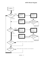
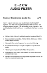
AVS10 Block Diagram
Micro
Initialization
Check
Switch
1
Video
Enabled
Turn ON
Video 1
Conrol Line
1 to 5
Second
Delay
Turn OFF
Video 1
Conrol Line
Check
STOP/SCAN
Switch
Video
Disabled
STOP/SCAN
Not Pressed
STOP/SCAN
Pressed IN
Check
Switch
2
Video
Enabled
Turn ON
Video 2
Conrol Line
1 to 5
Second
Delay
Turn OFF
Video 2
Conrol Line
Check
STOP/SCAN
Switch
Video
Disabled
Check
Switch
3
Check
Switch
4
STOP/SCAN
Not Pressed
Check 3 the same as switch 1 and 2 above.
Check 4 the same as switch 1 and 2 above.
AVS10 – 5
STOP/SCAN
Pressed IN
PARTS LIST
RESISTORS
1 1K ohm resistor [brown-black-red] (R1)
1 5.6K ohm resistor [green-blue-red] (R3)
4 10K ohm resistor [brown-black-orange] (R4,5,6,7)
1 10K PC mount potentiometer (R2)
CAPACITORS
1 100 pF ceramic disc capacitor [marked 100, 101, or 100K] (C1)
2 .01 µF ceramic disc capacitors [marked .01, 103, or 10nF] (C2,3)
1 10 µF electrolytic capacitor (C5)
1 470 µF electrolytic capacitor (C4)
SEMICONDUCTORS
1 1N4004 diode (D1)
1 7805 5 volt regulator (VR1)
1 4066 quad analog switch (U2)
1 MC68HRC908JK1 programmed chip (U1)
HARDWARE AND MISCELLANEOUS
5 RCA-type PC-mount jack (J1,2,3,4,5)
1 2.1mm PC mount power jack (J6)
1 20 pin IC socket (for U1)
2 DPDT PC-mount pushbutton switches (S2,3)
1 DIP switch (8 pin dip with 4 sliding tabs) (S1)
AVS10 – 6
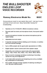
AVS10 PARTS LAYOUT DIAGRAM
AVS10 – 7
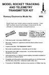
AVS10 – 8
ASSEMBLY INSTRUCTIONS
In ALL PC board assembly steps, our word "INSTALL" means to do this:
Insert the part, oriented or "pointed" correctly, into its holes in the PC
board.
If helpful, gently BEND the part's wire leads or tabs to hold it in place,
with the body of the part snugly against the top side ("component side")
of the circuit board. The “component side” is silkscreened with the part
numbers for easy parts location identification.
Solder ALL wires or pins of the part.
Trim or "nip" all excess wire lengths extending beyond each solder
connection, taking care that wire trimmings do not become lodged in
solder connections.
Follow the assembly instructions IN SEQUENCE and check off each step as
understood and completed. Examine the schematic circuit diagram and PC
Board parts layout diagram as you proceed.
Use good soldering techniques! Let your soldering iron tip heat both the
component lead wire and PC board trace enough so that the wire itself AND
the foil trace BOTH become hot enough TOGETHER to melt a bit of solder
so that it flows smoothly from the pin to the PC board trace.
Enough said... Let’s get building!
As you build your video switcher kit save the clipped off leads from
capacitors and resistors. These will be needed later to form jumpers that
allow the circuit traces to run along both sides of the PC board. If you throw
out your lead scraps you’ll have to find buss wire to make these important
connections.
1. Install U2, the quad analog switch. To ensure that the part is seated
flat on the PC board, mount the part and place the circuit board
component side down on the table top before soldering the leads. This
will keep the IC from moving while you solder it. Be sure to solder all 14
pins.
2. In the same way, install the 20 pin IC socket. As with the IC installed
in step 1, be sure you seat the socket flush with PC board before
soldering.
AVS10 – 9
3. Install U1, the MC68HRC908JK1 programmed chip [20 pin chip with
paper label] into the IC socket. Check the orientation before installing.
The chip is marked with a dot or notch on one end which must be lined
up with the notched end shown on the PC board silkscreen and parts
layout diagram.
4. Install S2, the DPDT pushbutton switch. Be sure it is flat to the PC
board before soldering.
5. Install S3, the other DPDT pushbutton switch.
6. Install R3, 5.6K ohms (green-blue-red).
7. Install R1, 1K ohm (brown-black-red).
8. Install R4, 10K ohm (brown-black-orange).
9. In the same way, install R5, R6, and R7, all 10K ohm (brown-blackorange).
10. Install S1, the 8 pin DIP switch. Orient the switches toward the
outside of the PC board, away from R7.
11. Install R2, the 10K ohm PC mount potentiometer. Seat the part flat
on the PC board and solder all five connections.
12. Install J6, the +12 VDC input power jack.
13. Install C1, a 100 pF ceramic disc capacitor (marked 100, 101, or
100K).
14. You will now need to install the first of your jumper wires. Before
installing in the PC board you will need to form a clipped off lead (saved
from previous steps) into what looks like a staple whose width
corresponds to the hole spacing on the board marked JMP5. Once
formed, install the wire just as if it were a resistor, bend the leads out on
the solder side of the board to keep it from falling out, and solder. It will
be a help to get the spacing right on this one as sort of a pattern for you
because you’ll be installing several more jumpers along the way.
15. Install C2 and C3, the .01µF ceramic disc capacitors (marked .01,
103, or 10nF]).
16. Install VR1, the 7805 5 volt regulator. This part ensures a clean DC
voltage for your kit. You will want to bend the center lead out slightly for
a good fit into the PC board. Solder all three leads.
17. Install D1, the 1N4004 diode. Diodes have a polarity and must be
installed correctly to work properly. You will notice that one end of the
diode is marked with a band. Be sure to orient this banded end as
shown on the parts layout diagram and PC board silkscreen.
AVS10 – 10
18. Install C5, 10µF electrolytic capacitor. Electrolytic capacitors also
have a polarity and must be installed properly. You will note a “+”
symbol on the PC board silkscreen. This marks the positive side of the
capacitor. Most manufacturers mark the negative side of the cap with a
band containing minus signs (“-”) or zeros. Also, the capacitor has a
long and a short lead. The short lead is the negative. Orient the
capacitor properly and solder in place.
19. In the same way, install C4, a 470 µF electrolytic cap. Check
polarity before installing.
It is now time to install the rest of the wire jumpers. Take a look back at step
14 to refresh your memory if necessary, then form the four jumpers you will
need.
20. Install the jumpers marked JMP1, JMP2, JMP3, and JMP4.
21. Install the RCA jack, J1. This is another part you will want to be
careful to seat properly before soldering. Be sure to solder all four tabs.
Three of the tabs are connected to ground and provide stablility for the
part as you plug your cables into and out of it. Also, a good ground
connection helps you get a good, clean signal so be sure to get a solid
solder joint on these connections.
22. In the same way, install J2, J3, J4, and J5. You may need to be
patient to get good solder flow to the ground leads.
You’ve completed construction of your AVS10 video switcher kit! We know
you’re anxious to plug your kit in and turn it on but before you do that, take a
moment to look over your work. Check your solder joints and parts
placement. Also, be sure the programmed chip is seated properly in the
socket and that the polarity is correct on both chips. Now would be a good
time to check the polarity on the electrolytic capacitors as well.
AVS10 – 11
INITIAL TESTING
If any of the following steps fail to produce the desired result, turn to the troubleshooting section of the manual (below). You will need at least one video
source, power for that source, and RCA cables to connect the source to the
video input of the AVS10 and to connect the output of the AVS10 to your
monitor. The number of cables you need depends on the number of video
sources you are connecting.
•
Connect your 12VDC power supply to the AVS10. Be sure it is positive tip!
•
Connect one or more video sources to the inputs, J1 through J4. Be sure
your video sources are properly powered.
•
Connect the video output, J5, to your monitor (television or VCR). Depending on your TV, you may need to set up the input in the menu section. Consult your TV owners manual for help with this.
•
Select the video inputs to be enabled by switching the appropriate input
on S1. Ex. J1 = VIDEO 1.
•
Turn on the AVS10. With the SCAN/STOP button out (or off) you should
see each of the sources you connected cycle through in sequence on
your monitor.
•
Vary the Scan Speed using R2.
•
Push in the SCAN/STOP button to select a single video source for constant presentation. Releasing the SCAN/STOP switch will restart the cycling of all enabled video sources.
•
Stand back and admire your work! Your AVS10 is functioning properly.
TROUBLESHOOTING GUIDE
If your AVS10 does not work at all, recheck the following:
•
Correct orientation of U1 and U2 (see PC board layout diagram). Also
check to be sure that all pins of the IC are installed in the socket and none
are bent under or sticking out.
•
Correct polarity of all electrolytic capacitors.
•
Correct orientation of diode D1 and voltage regulator VR1.
AVS10 – 12
•
Correct installation of all jumpers.
•
Check the polarity on your power supply. The AVS10 requires a positive tip supply!
If you still cannot get the unit to function, read the warranty instructions on
page 15. A simple recheck of your construction will usually solve any problems.
CONCLUSION
We sincerely hope that you will enjoy the use of this Ramsey product. As always, we have tried to compose our manual in the easiest, most “user
friendly” format that is possible. As our customers, we value your opinions,
comments, and additions that you would like to see in future publications.
Please submit comments or ideas to:
Ramsey Electronics Inc.
Attn. Hobby Kit Department
590 Fishers Station Drive
Victor, NY 14564
And once again, thanks from the folks at Ramsey!
AVS10 – 13
AVS10 – 14
The Ramsey Kit Warranty
Please read carefully BEFORE calling or writing in about your kit. Most problems can be solved
without contacting the factory.
Notice that this is not a "fine print" warranty. We want you to understand your rights and ours too! All
Ramsey kits will work if assembled properly. The very fact that your kit includes this new manual is
your assurance that a team of knowledgeable people have field-tested several "copies" of this kit
straight from the Ramsey Inventory. If you need help, please read through your manual carefully, all
information required to properly build and test your kit is contained within the pages!
1. DEFECTIVE PARTS: It's always easy to blame a part for a problem in your kit, Before you conclude
that a part may be bad, thoroughly check your work. Today's semiconductors and passive components
have reached incredibly high reliability levels, and it’s sad to say that our human construction skills
have not! But on rare occasions a sour component can slip through. All our kit parts carry the Ramsey
Electronics Warranty that they are free from defects for a full ninety (90) days from the date of
purchase. Defective parts will be replaced promptly at our expense. If you suspect any part to be
defective, please mail it to our factory for testing and replacement. Please send only the defective part
(s), not the entire kit. The part(s) MUST be returned to us in suitable condition for testing. Please be
aware that testing can usually determine if the part was truly defective or damaged by assembly or
usage. Don't be afraid of telling us that you 'blew-it', we're all human and in most cases, replacement
parts are very reasonably priced.
2. MISSING PARTS: Before assuming a part value is incorrect, check the parts listing carefully to see
if it is a critical value such as a specific coil or IC, or whether a RANGE of values is suitable (such as
"100 to 500 uF"). Often times, common sense will solve a mysterious missing part problem. If you're
missing five 10K ohm resistors and received five extra 1K resistors, you can pretty much be assured
that the '1K ohm' resistors are actually the 'missing' 10 K parts ("Hum-m-m, I guess the 'red' band really
does look orange!") Ramsey Electronics project kits are packed with pride in the USA. If you believe
we packed an incorrect part or omitted a part clearly indicated in your assembly manual as supplied
with the basic kit by Ramsey, please write or call us with information on the part you need and proof of
kit purchase
3. FACTORY REPAIR OF ASSEMBLED KITS:
To qualify for Ramsey Electronics factory repair, kits MUST:
1. NOT be assembled with acid core solder or flux.
2. NOT be modified in any manner.
3. BE returned in fully-assembled form, not partially assembled.
4. BE accompanied by the proper repair fee. No repair will be undertaken until we have received the
MINIMUM repair fee (1/2 hour labor) of $25.00, or authorization to charge it to your credit card
account.
5. INCLUDE a description of the problem and legible return address. DO NOT send a separate letter;
include all correspondence with the unit. Please do not include your own hardware such as
non-Ramsey cabinets, knobs, cables, external battery packs and the like. Ramsey Electronics,
Inc., reserves the right to refuse repair on ANY item in which we find excessive problems or
damage due to construction methods. To assist customers in such situations, Ramsey
Electronics, Inc., reserves the right to solve their needs on a case-by-case basis.
The repair is $50.00 per hour, regardless of the cost of the kit. Please understand that our technicians
are not volunteers and that set-up, testing, diagnosis, repair and repacking and paperwork can take
nearly an hour of paid employee time on even a simple kit. Of course, if we find that a part was
defective in manufacture, there will be no charge to repair your kit (But please realize that our
technicians know the difference between a defective part and parts burned out or damaged through
improper use or assembly).
4. REFUNDS: You are given ten (10) days to examine our products. If you are not satisfied, you may
return your unassembled kit with all the parts and instructions and proof of purchase to the factory for a
full refund. The return package should be packed securely. Insurance is recommended. Please do not
cause needless delays, read all information carefully.
AVS10 – 15
AVS10 AUTOMATIC VIDEO SWITCHER
Quick Reference Page Guide
Introduction to the AVS10
Circuit Description
Initial Testing
Troubleshooting
Ramsey Warranty
REQUIRED TOOLS
• Soldering Iron (WLC100)
• Thin Rosin Core Solder (RTS12)
• Needle Nose Pliers (MPP4 or RTS05)
• Small Diagonal Cutters (RTS04)
ADDITIONAL SUGGESTED ITEMS
•
•
•
Helping Hands Holder for PC Board/Parts (HH3)
Technician’s Tool Kit (TK405)
Desoldering Braid (RTS08)
Manual Price Only: $5.00
Ramsey Publication No. MAVS10
Assembly and Instruction Manual for:
RAMSEY MODEL NO. AVS10 AUTOMATIC VIDEO SWITCHER
RAMSEY ELECTRONICS, INC.
590 Fishers Station Drive
Victor, New York 14564
Phone
(585) 924-4560
Fax
(585) 924-4555 AVS10 – 16
www.ramseyelectronics.com
4
4
6
8
11