1
THE BULLSHOOTER
ENDLESS LOOP
VOICE RECORDER
Ramsey Electronics Model No.
BS2C
Announcing an event is now easier than ever! Just say it once
and hear it over and over. Easy transmitter hookup for
broadcasting.
•
Operates on 5 to 12 Volts DC, 250mA at maximum volume.
•
Records both line levels and microphone levels, front panel switchable.
•
Internal microphone included, has external microphone jack for
higher fidelity.
•
Adjustable line level output.
•
8 separate message locations totaling up to 8 minutes, or combine
into one 8-minute message.
•
Up to a 8kHz sample rate for good audio reproduction to 3.4kHz.
•
Digital speaker volume control and 8 ohm speaker output.
•
Single-Play and continuous repeat mode with programmable
delays : 0sec, 0.5sec, 5sec, 30sec, 1min, 10min, 30min, 60min.
•
Easy to record a message and allows monitoring of recording
session for easy level adjustment.
•
Lock mode which prevents user tampering once set up. (multiple
key combination to lock/unlock)
•
Non-volatile message storage capable of retaining recording for
over 100 years without power.
BS2 • 1
RAMSEY TRANSMITTER KITS
• FM100B Professional FM Stereo Transmitter
• FM25B Synthesized Stereo Transmitter
• AM1, AM25 AM Transmitters
• TV6 Television Transmitter
RAMSEY RECEIVER KITS
• FR1 FM Broadcast Receiver
• AR1 Aircraft Band Receiver
• SR2 Shortwave Receiver
• AA7 Active Antenna
• SC1 Shortwave Converter
RAMSEY HOBBY KITS
• SG7 Personal Speed Radar
• SS70A Speech Scrambler
• SP1 Speakerphone
• WCT20 Wizard Cable Tracer
• PH10 Peak hold Meter
• LC1 Inductance-Capacitance Meter
RAMSEY AMATEUR RADIO KITS
• DDF1 Doppler Direction Finder Kit
• HR Series HF All Mode Receivers
• QRP Series HF CW Transmitters
• CW700 Micro Memory CW Keyer
• CPO3 Code Practice Oscillator
• QRP Power Amplifiers
RAMSEY MINI-KITS
Many other kits are available for hobby, school, Scouts and just plain FUN. New
kits are always under development. Write or call for our free Ramsey catalog.
ENDLESS LOOP VOICE RECORDER INSTRUCTION MANUAL
Ramsey Electronics publication No. MBS2 Rev 1.3
First printing: May 2004
COPYRIGHT 2004 by Ramsey Electronics, Inc. 590 Fishers Station Drive, Victor, New York
14564. All rights reserved. No portion of this publication may be copied or duplicated without the
written permission of Ramsey Electronics, Inc. Printed in the United States of America.
BS2 • 2
Ramsey Publication No. MBS2
Price $5.00
KIT ASSEMBLY
AND INSTRUCTION MANUAL FOR
THE BULLSHOOTER
ENDLESS LOOP
VOICE RECORDER
TABLE OF CONTENTS
Introduction ............................................ 4
Circuit Description.................................. 5
BS2C Parts List...................................... 7
Parts Layout Diagram ............................ 9
Assembly Procedure............................ 10
Schematic Diagram.............................. 14
Initial Testing and Operation ................ 20
Using the BS2C ................................... 20
Case Up Instructions............................ 25
Troubleshooting ................................... 26
Warranty............................................... 27
RAMSEY ELECTRONICS, INC.
590 Fishers Station Drive
Victor, New York 14564
Phone (585) 924-4560
Fax (585) 924-4555
www.ramseykits.com
BS2 • 3
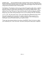
INTRODUCTION
Each of us at one time or another has probably heard an endless loop player
repeating a list of movies playing at the local theatre, or advertising a house for
sale through your car radio. Sure could be handy around the house
occasionally, or maybe down at the local flea market. Could you modify a
cassette or CD player to duplicate this function? Good luck! Where could you
even find that sort of machine anyway, and how much would it cost? Enter the
BS2C Bullshooter.
As a stand alone unit, the BS2C is perfect for the task of, say, announcing
repetitive instructions at an event: “All vendors please report to the registration
desk located at the …“. Connected to one of our personal broadcasters like the
FM25B, the BS2C is ideal for advertising neighborhood garage sales or school
or church functions. How about a look at the BS2C?
You will notice right away that the Bullshooter isn’t your average tape player. In
fact, utilizing one of the latest voice recording chips on the market, the BS2C
performs its job without need of a tape. There are no motors, drive belts, or
gears to wear out. With the exception of the front panel controls, there are no
moving parts at all! In addition, the endless loop playback feature makes the
Bullshooter a truly unique device.
A quick push of the RECORD and PLAY buttons sets up the BS2C to record up
to a full eight minutes of audio, depending on how you have set up the sample
rate, and what message location you start at (See “Using the BS2C”). Use the
on-board microphone to record a quick message or press both UP DOWN keys
to enable use of the line level input for recording from other sources; cassette,
CD, radio, etc. A “Record” LED serves as the record mode indicator and
extinguishes when the maximum memory capacity has been reached or you
press STOP.
The PLAY button selects playback mode which is set up for single play
operation by default. The message recorded will continue playback indefinitely,
looping over and over for as long as the unit remains in play mode. Through
programming of the internal microcontroller the message will always start from
the beginning, thus negating the need for rewinding. The “Play” LED simply
serves as an indicator for playback mode.
The Bullshooter features two sets of audio outputs to best suit the application
at hand. The speaker output (volume controlled by the front panel UP/DOWN
buttons) has sufficient power to drive most speakers well into normal listening
volumes. Although being a monaural device, twin line level outputs are
provided for connection to equipment such as mixers, amplifiers, or transmitters
which would normally require left and right inputs.
BS2 • 4
BS2C CIRCUIT DESCRIPTION
We will go through the BS2C section by section, but most circuitry that used to
be in separate circuits in the BS1 has been fully integrated into the BS2C main
chip. For example, you can switch between the microphone and line inputs
digitally so you can select them using the front panel switches. The part also
contains a speaker power amplifier so we no longer need a separate IC for this.
The BS2C power supply: The power supply is fairly basic in that we only need a
single voltage to run the entire kit. The trend these days is to run things from
lower voltages for faster operation and less power requirements, so all of the
parts in the BS2C run from 3.3V. VR1 is a low-dropout 1.5 Amp regulator,
though we will hopefully never pull that much current with the BS2C during
operation. This part “smoothes” out the incoming, usually noisy wall wart power
supply voltage into a nice, clean, predictable voltage to supply all of the other
components.
The BS2C “brains”: The brain of this kit is a nice Motorola microcontroller, the
MC68HRC908JK1. This part contains 1.5K of ROM for all the memory required
for the program and space saving settings. Compare that to your PC memory
space! This part is used to interpret the key presses, and then act on them by
controlling the voice recorder IC, U3. It also controls the LED display and
monitors for “End of Message” indications from U2, the voice recorder, to know
when to replay messages.
The BS2C sound recorder IC: This part is a fully integrated component, loaded
with options for switching audio, mixing audio, adjusting gains, changing
BS2 • 5
sample rates. . . all controlled through a serial access method (called SPI for
Serial Peripheral Interface) by the microcontroller. This truly is an amazing part!
There are so many features that we couldn't take advantage of them all, but are
using some of the best ones for this product.
The Display: The display is driven by a serial shift register rather than a display
decoder so we can have more versatility in the number of digits shown. The
same serial lines used for the voice recorder can be used to drive U4, making
efficient use of the I/O lines on the microcontroller. It has the added benefit of
being very low noise during operation so as not to interfere with the recording.
U1:A, U1:B, The line level circuit: This circuit takes the differential output from
the sound recorder and converts it to single-ended so that you can use it
properly on RCA type connections. It also provides for a bit of filtering and
some gain control to better match your system levels.
These are the primary blocks of circuitry in the BS2C. Now it is time to collect
your soldering iron, tools, and wits, and start putting this neat project together!
BS2 • 6
PARTS SUPPLIED WITH BS2C VOICE RECORDER KIT
Capacitors
9 0.1uF ceramic capacitors (Marked 104) [C5,7,9,11,13,15,17,19,20]
2 0.01uF ceramic capacitors (Marked 103) [C8,10]
1 10pF ceramic capacitor (Marked 10p or 10) [C18]
1 4.7uF Electrolytic capacitor [C12]
7 10uF Electrolytic capacitors [C1,2,4,6,16,21,23]
2 470uF Electrolytic capacitors [C3,14]
Resistors
1 330 ohm resistor (orange-orange-brown) [R15]
9 470 ohm resistors (yellow-violet-brown) [R17,25,26,28,29,30,31,32,33]
1 1k ohm resistor (brown-black-red) [R7]
5 2.2 k ohm resistors (red-red-red) [R9,11,14,16,18]
14 10k ohm resistors (brown-black-orange)
[R1,2,3,5,8,10,12,19,20,21,22,23,24,27]
1 10k ohm vertical trimmer pot [R13]
1 1k ohm horizontal trimmer pot (Marked 103, orange adjustment)[R6]
Semiconductors
1 1N4000 series diode (epoxy case marked 1N4000 to 1N4004) [D2]
1 Red LED [D6]
1 Green LED [D5]
1 LM1086CS-3.3 3.3Volt 1.5A voltage regulator [VR1]
1 LMC6482AIN Dual Rail to Rail Opamp IC [U1]
1 ISD5008P Voice Recorder IC [U2]
1 74HC595AN Serial to Parallel shift register IC [U3]
1 MC68HRC908JK1 Microcontroller IC (marked with white sticker) [U3]
1 7-segment display (LTS367P)
Inductors
1 22uH inductor (fatter than a resistor, red-red-black-gold) [L1]
Hardware, Misc.
6 Horizontal push-button switches [S2,3,4,5,6,7]
1 DPDT Power switch [S1]
2 3.5mm monaural style switch jacks [J5,12]
1 2.1mm Center-pin positive power jack [J1]
1 Single RCA jack [J9]
1 Dual RCA jack [J2]
1 20-pin socket for U3
1 28-pin socket for U2
1 MC-1 microphone cartridge [MC1]
3 8-pin dual-row headers [J6,8,11] (These are also [J4,7,10])
1 BS2C printed circuit board
BS2 • 7
Required, not supplied
6 Volt DC power transformer
Optional
Line level audio source (such as a tape deck or CD player)
Shielded stereo audio cables
Speaker
Case and Knob Parts
Top Cover
Bottom Base Tray
4 - Short Phillips Head Screws
2 - Long Phillips Screws
Front and Rear Plastic Panels with Labels
4 - Rubber Feet
Appropriate Knobs for Kit
Required Tools
Pen or Pencil
Small Phillips Head Screwdriver
Soldering Iron
60/40 Rosin Core Solder
Wire Clippers
Safety Glasses
BS2 • 8
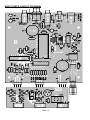
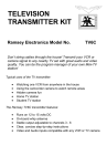
BS2C PARTS LAYOUT DIAGRAM
BS2 • 9
RAMSEY "LEARN-AS-YOU-BUILD" ASSEMBLY STRATEGY
As you can see in examining the circuit board and components, there is a bit
more to this voice recorder kit than just soldering a few parts. So that you don't
spend extra time "troubleshooting" instead of enjoying your new kit, we strongly
recommend that you follow the assembly strategy and step-by-step procedures
we provide.
Our strategy in installing parts on our PC board is to install the larger and more
obvious parts such as the connectors and controls. These parts will then act as
"landmarks" so that each additional device installed is seen in relationship to
them, or to others previously installed.
BS2C ASSEMBLY
Use the boxes to check off your progress.
Check all received parts against the Parts list on page 7 and 8. The parts list
describes the various markings that may be found on the kit parts.
In ALL the following instruction steps, our word "INSTALL" means this:
•
Insert the part, oriented correctly, into its correct holes in the PC board.
•
If helpful, gently BEND the part's wire leads or tabs to hold it in place, with
the body of the part snugly against the top "component side" of the PC
board.
•
SOLDER ALL wires or pins of the part, whether the two wires of a resistor
or every pin of an IC socket.
•
Nip or "trim" all excess wires extending beyond each solder connection,
taking care that wire trimmings do not become lodged in PC board solder
connections.
Enough said. . . Let's get building!
BS2 • 10
Since you may appreciate some “warm-up” soldering practice as well as a
chance to put some “landmarks” on the PC board, we’ll first install some of the
larger components. Have a look at the Parts Layout Diagram to help with your
assembly.
We’ll start with the larger PC board and work our way through that before
tackling the smaller front panel board. The first parts we’ll install will be the IC
sockets, and there’s a reason for that. If we install them first while there are
no other parts on the board you'll be able to lay the board flat on the ICs while
soldering and that will ensure that the parts are lying flat on the PC board.
Let’s begin with the chips that don’t use a socket, then the socketed parts.
1. Install U4, the 74HC595AN Serial to Parallel shift register. The part
has a notch or dot on one end and so does the PC board silkscreen for
that part. You can also see the notch on your Parts Layout Diagram. Align
the notch on the part as shown on the drawings. Be sure that all the pins
are through the board, that none are bent under or out, and make sure the
part is sitting flat before soldering all the leads. It’s helpful to solder two of
the corner pins to hold the IC in place, check the placement, and then
solder the rest of the pins.
2. In the same way, install U1, the LMC6482AIN dual rail to rail opamp
chip. Line up the notch on the part with the notch shown on the PC board
silkscreen and Parts Layout Diagram. Be sure all 8 leads are through the
board and the part is flat before soldering them in.
3. Next we’ll install the socket for U3. The socket has a notch similar to
the one on the PC board simply to make it easier to orient the part once
you’re ready to install it in the socket. As with the ICs before, make sure
all pins are through and the part is flat before soldering. We’ll install the
next part before placing the ICs into their sockets, again so that you can
rest the board on the part being soldered and get it set in the board
correctly.
4. Install the socket for U2. Orient the notch, place the part flush with
the surface and solder all the leads.
5. Take U3, the microcontroller IC marked with a sticker and place it in
the socket installed in step 3. You might want to gently roll the pins on one
side, then the other, to make the part slip into the holes more easily.
Remember to orient the notch as shown on the silkscreen and Layout
Diagram.
6. In the same way, place U2 in its socket. Check that all pins are in the
socket, not bent underneath or outside the holes.
7 Install S1, the DPDT power switch. Be sure it’s flush to the PC board
before soldering all 6 pins.
8. Install D2, the 1N4000 series diode. This component has a polarity
BS2 • 11
which means that it must be installed in the proper orientation to work
correctly. You’ll note that there’s a stripe or band at one end of the part and
a band marked on the PC board silkscreen and Parts Layout Diagram.
Align the two bands and solder the diode in place.
9. Install C3, 470uF electrolytic capacitor (marked 470uF). Because this
is an electrolytic cap it has a polarity and must be installed correctly in order
to function. The other little quirky thing about electrolytic caps is that they
tend to explode when installed backwards. We’re not trying to scare you,
just make you aware of the fact that care is needed when installing this part
and all the other electrolytic caps. You’ll see a band or stripe down one
side of the part. This band typically has zeros or minus signs in it and
denotes the negative lead. If they have not been clipped off, one of the
leads should also be shorter than the other. The short lead is also the
negative. The PC board silkscreen has a ‘+’ sign on it to show you where
the positive lead should be placed. With this in mind, place C3 with the
longer positive lead in the hole marked with the ‘+’ sign and solder it in
place. Since it’s a large part you’ll want to have it flush to the PC board
before soldering. In fact, unless we tell you to do something different, make
sure that all of your parts are down as close to the PC board as possible.
It’s good practice, especially in RF circuits, and your board will look neatly
and professionally done if you keep the parts low.
10. Next install C23, 10uF electrolytic cap, right next to C3 (marked 10uF).
As in the last step, follow the ‘+’ sign for correct placement.
11. Install VR1, an LM1086CS-3.3 voltage regulator (3.3 volts). The body
of the part is meant to lay down on the silver square on the board and you’ll
want to solder it to the board at that point. Simply melt some solder onto
the square, then bend the three leads of the part so that it can lay flat.
Place the leads through the board and solder them, then heat up the metal
tab on the regulator while pressing it down onto the silver square. This will
heat the solder underneath and secure the part to the board. It’s not critical
so if you can’t get it to solder, don’t worry about it. It’s just a bit of extra
mechanical strength and provides more of a heatsink, but we’ve yet to see
that part get warm so it’s not going to affect your kit if you don’t do it.
12. Install C4, another electrolytic capacitor (marked 10uF). Remember to
orient the part so that the positive lead is in the hole marked with a ‘+’ sign.
OK, that was a good warm-up. Let’s take a look at those solder joints to make
sure we’re in good shape to move on. A good solder connection should be
shiny, smooth, and solid. No room for loose connections here! An old trick is to
wipe the hot tip of the iron across a damp sponge before soldering each
connection. This keeps the tip clean and spreads the heat faster for a solid
connection. If you haven’t tried it, give it a shot and see how much easier it
goes.
BS2 • 12
Those last few parts are the power supply section of our kit, taking the raw
DC input to the kit and smoothing it out for all the circuits. Ready to move
on?
13. Install R3, 10k ohms (brown-black-orange). Resistors can be
installed in either direction but your kit will look better if you have all the
gold bands lined up the same way.
14. Install R7, the only 1k ohm resistor in this kit (brown-black-red).
Check the color code to be sure that the red stripe is really red and not
orange like the 10k’s.
15. Install C8, 0.01uF ceramic disc cap (marked 103, .01, or 10nF). .
16. Install C1, 10uF electrolytic capacitor. Remember to watch the
polarity when installing.
The next part is mounted in standup fashion, meaning that one lead is placed
through the circuit board and the other lead is bent around and then placed
through the board. The part is placed upright rather than flat like the other
resistors we’ve installed so far.
17. Install R9, 2.2k ohms (red-red-red). The body of the part is placed in
the hole marked with a circle and the other lead is bent over to fit in the
other hole. Again, keep the lead lengths short and the part flush to the
board.
18. Install R2, 10k ohms (brown-black-orange).
19. Install R1, also 10k ohms (brown-black-orange).
20. Install C9, 0.1uF ceramic disc capacitor (marked 104).
21. Install C2, 10uF electrolytic capacitor (marked 10uF). Remember to
watch the polarity.
22. Install C10, 0.01uF ceramic disc capacitor (marked 103, .01, or
10nF).
23. Install R10, 10k ohms standup (brown-black-orange).
24. Install R8, 10k ohms (brown-black-orange). Again, mount this part
standing up.
25. Install R5, another 10k ohm resistor (brown-black-orange).
26. Install C7, 0.1uF ceramic disc capacitor (marked 104).
27. Install C5, 0.1uF ceramic disc capacitor (marked 104).
28. Install C12, the lone 4.7uF electrolytic capacitor. Again, watch the
way it’s installed and make sure the positive lead goes in the positive
hole.
BS2 • 13
BS2 • 14
BS2 • 15
29. Install C16, 10uF electrolytic cap. Yes, watch the polarity again.
30. Install R27, 10k ohms (brown-black-orange).
31. Install R14, 2.2k ohms (red-red-red).
32. Install R11, another 2.2k ohm resistor (red-red-red).
33. Install R16, 2.2k ohms (red-red-red). It’s hiding between the MIC and
LINE IN jacks.
34. Install C11, 0.1uF ceramic disc capacitor (marked 104).
35. Install C13, 0.1uF ceramic disc capacitor (marked 104).
36. Install C14, the other big 470uF electrolytic capacitor. This is another
part where it pays to be careful about the polarity, since the larger the cap,
the bigger the bang if it blows up! Just follow the ‘+’ marking like you have
been and everything will be fine.
Now is a good time to double check your work. Loose pins, solder bridges, or
an improperly installed IC can really throw a wrench into the works. It’s also a
good time to take a break and maybe rub your eyes before you get back into it.
37. Install C20, 0.1uF ceramic disc capacitor (marked 104). It’s nice not to
have to worry about the polarity of these ceramic disc caps, isn’t it?
38. Install L1, 22uH inductor (red-red-silver bands). This part is very similar
to a resistor but fatter around the middle. It’s the only part with those color
bands so you shouldn’t have any trouble identifying it. It has no polarity so
just insert and solder it.
39. Install C15, 0.1uF ceramic disc capacitor (marked 104).
40. Install R12, 10k ohms (brown-black-orange).
41. Install C18, 10pF ceramic disc capacitor (marked 10).
42. Install C19, 0.1uF ceramic disc capacitor (marked 104).
43. Install C17, another 0.1uF ceramic disc capacitor (marked 104). This
part is kind of squeezed in at the end of U3 but I’m sure you can fit it in
there.
44. Install C21, 10uF electrolytic (marked 10uF). This part is a tight fit too,
but it’s taller so that should be easier for you.
Next we’ll move to the center of the board and install a row of the same
value resistors. They’re all 470 ohms (yellow-violet-brown). Start with R33
and work your way through R32, R31, R30, R29, R28, R25, to R26. There,
killed 8 parts with 1 step!
45. Install R23 and R24, both 10k (brown-black-orange).
46. Install R17, the last 470 ohm (yellow-violet-brown).
BS2 • 16
47. Install R19, 10k ohms (brown-black-orange).
48. Install R15, 330 ohms (orange-orange-brown).
49. Install R20, 21, and 22, all 10k ohms (brown-black-orange).
50. Now we’ll move to the other end of the PC board. Install C6, 10uF
electrolytic capacitor. Watch orientation!
51. Install R6, the 1k ohm vertical trimmer pot (marked 102). It only fits into
the board one way. Solidly solder all three pins.
52. Install J12, the 3.5mm monaural style switch jack. Be sure the part is
flat to the board before soldering, otherwise you’ll have a hard time fitting
the kit into the case and having things line up where they should. This part
is your external speaker jack.
53. Install the dual RCA jack, J2. This is your line output jack.
54. Install J5, the other 3.5mm monaural style switch jack. This is your
microphone jack.
55. Install J9, the single RCA jack that will be used for line level audio
input. It’s important to solder the heavier ground connections on this type
of jack so use enough heat and time to make a solid connection here. It’ll
pay off when you’re using the kit!
56. Install J1, the 2.1mm center positive power jack.
Time to move on to the smaller front panel board. Just a few parts there and
we’ll solder the boards together, then you’ll be just about ready to fire up your
Bullshooter. Pretty exciting, huh? Well, let’s get moving then!
57. We’ll start at the middle of the board with the smallest part. Install R18,
2.2k ohms (red-red-red). We started with this one because it’s small and
sits flat on the board and would be difficult to put in later when you’d have
to squish it in between the larger parts.
58. Install DS1, the seven segment display (LTS367P). You’ll see that
there is a decimal point in one of the corners of the part. Orient the display
so that the decimal point will be at the lower right when you’re looking at the
front of the unit. You should be able to rest the board on this part to keep it
flat when soldering but you’ll also want to check it to be sure it’s square.
Solder all 6 leads.
59. Now we’ll install the LEDs. D6 is the red LED and D5 is the green LED.
Being diodes, these components are polarized and must be oriented
correctly. Examine one of the LED’s and notice how one lead is longer
than the other. The longer of the two leads is the anode, or (+) connection.
Most diodes also have a flat molded in the component body. This
corresponds to the cathode or (-) side of the part. You’ll see that the PC
board silkscreen for these parts shows a flat side that corresponds to the
BS2 • 17
flat side on the part. Line these flat sides up and the diodes will be
installed correctly. If installed backwards they will never light. Install D6,
the red LED, by correctly orienting the flat side on the part with the flat
side shown on the PC board silkscreen and Parts Layout Diagram. Leave
the leads between the bottom of the part and the PC board at least 1/2
inch long. Solder both leads. When you clip the leads off the back of the
board leave a little extra on this part and on D5. This will allow you to line
the LEDs up with the hole in the front panel and make sure they push
through enough to be seen. We’ll get to how to do that when we attach
the two boards together and put them in the case. In the same way that
you installed D6 above, install D5, placing the flat side correctly and
leaving excess lead length on the back. You can clip the leads off later if
you wish.
60. Install S2, one of the horizontal pushbutton switches. Be sure it’s
flush before soldering.
61. In the same way, install S3, S4, S5, S6, and S7, making sure the
parts are sitting correctly on the board and soldering all 4 leads of each
switch. These are the function buttons and you’ll be pressing them a lot
as you use your kit.
62. Install MC1, the small microphone cartridge. Because the case is
connected to the ground lead on the part and that lead is not attached to
ground in this kit you’ll want to leave a bit of space between the body of
the microphone and the PC board. This is one of the times we won’t tell
you to make sure that the part is flat to the board before soldering! Line
the part up in the circle on the silkscreen, leave a little space underneath
the part (1/16 of an inch is fine) and solder it in place.
63. Install R13, the 10k ohm vertical mount pot. You might need some
extra time on the ground connections on this part but it’s worth it to make
it solid now. You’ll be adjusting this part and you’ll want a good
mechanical connection from the start.
64. Now we’ll install the three 8 pin dual row headers to the front panel.
These will be used to connect the two boards together. Let’s start with J6.
Place the header through the PC board so that the long pins come out the
back of the board on the solder side. Line it up so that it’s straight and
solder one of the end pins, then check straightness again before soldering
the rest.
65. In the same way, solder the 8 pin headers in the J11 and J8 positions.
Ok! All the parts are in but we’re not quite through. We still have to attach the
boards together, test your new BS2 and case it up. Before applying power it
would be a good idea for one last glance over the entire PC board. Check for:
•
Missed solder joints.
BS2 • 18
•
Solder shorts between components. Check your schematic and parts
layout diagrams if you suspect a fault.
•
Proper orientation of diodes, capacitors, and ICs.
•
Ensure proper power supply polarity and voltage (5 to 12 volts DC, center
positive)
All finished checking your kit over? I went and got a glass of water to give you
time to thoroughly examine your solder joints and parts placement, knowing
that you wouldn’t want to leave me sitting here idly waiting for you. Now that
we’re both back, let’s attach the boards together and test this baby out!
66. Locate the bottom half of your clamshell case; it’s the one with the
mounting posts for your board screws in it. While you’re at it, find a couple
of the short Phillips head screws and the prepunched front panel. Since
we’re talking about the front panel, take a look at yours now. You’ll see a
place labeled “Input Level”. That label should be under the large
potentiometer labeled “Volume”. Yes, we goofed. The volume is actually
controlled by the UP/DOWN buttons, and the pot is for adjusting the line
level input if you need to. Sorry for any confusion. Now, back to what we
were doing. Place the front panel into either end of the clamshell case,
sliding it into the slots provided; it doesn’t matter which end it goes into.
Put that aside for a second; we’ll get back to it.
67. Take the main PC board and line the smaller front panel board up to
the main board so that the dual header pins can be soldered to the
corresponding pads on the main board. All lined up? Good! Don’t grab
your soldering iron yet, though. We’re going to be sure that the front panel
PC board fits up against the kit’s front panel before permanently attaching
the boards together. When they’ve been soldered together they’ll want to
stay that way, meaning that it’s a bear to get them apart again. We’ll try to
do this right the first time!
68. Once the boards are lined up and together, place the combined but
not yet soldered boards into the bottom of the case. To do this you’ll slide
the front panel components through the front panel and then line the main
board up with the screw holes in the bottom of the case. Don’t worry if the
front panel isn’t lined up perfectly yet; that’s what we’re tweaking right
now. Use the two screws you located earlier to attach the main board to
the case so that you know how it’s going to line up. It’s best to use a
couple of screws kitty-corner from each other. You simply have to have
the board in place, you don’t have to tighten the screws down tightly.
69. Now that the board is temporarily screwed into place, take the front
panel board that hasn’t been soldered to the main board yet and pull it
forward to where you want it to line up with the front panel. You’ll want
the buttons and LEDs to poke out and look good, and you’ll want things to
BS2 • 19
be flush and square. Once you have things where you want them, take
your soldering iron and tack solder the two outside pins of the two outside
8 pin headers to hold the whole thing in place.
70. Now is the time to check your LED placement, while the header solder
joints cool and before you pull the main board back out. If the LEDs poke
through the case as far as you want them to, then you’re finished with this
step. If they stick out too far and are pushing the front panel out you’ll
want to heat both pads of each LED and when the solder is flowing, push
the LED to the position you desire. The same is true if you want to push
the LEDs out so that they poke through the case farther than they are
currently. You run the risk of losing the pads for the LEDs so you’ll only
want to do this once. In other words, if they look fine where they are,
leave them alone. If they don’t fit in correctly, here’s the procedure for
moving them. Choose which LED you want to move and place your
soldering iron tip between the pads of the LED, heating both pads at once.
Once the solder is heated you can either push the LED back with a
fingertip or move it forward with needlenose pliers to the correct position
in the front panel. Once you take the iron away things will cool and you’ll
have the LED where you want it. If necessary, do the same with the other
LED. Again, if they look good, don’t bother changing things.
71. You can take the main board out of the case now and carefully solder
all the pins of the three 8 pin headers. These are the control lines and
connections to the main board from the front panel board so be careful
and do a good job.
We’re just about finished now; all we have to do is test the kit and then case it
up.
INITIAL TESTING AND OPERATION
Power Supply Considerations
The BS2C is designed to run off an external source of 5 to 12 VDC. Batteries,
power supplies, or AC adapters may be connected to the unit through the
power jack, J1. Care should be taken to ensure that the center tip is positive.
Before applying power make sure the volume control is turned down.
You’ll need to read the following section on using the BS2C to familiarize
yourself with the operation of the kit before testing can begin.
BS2 • 20
1
2
3
4
5
6
7
8
2
3
4
5
6
7
8
Time
1
Time
EOM
1
2
3
4
5
6
7
8
Time
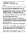
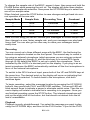
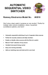
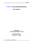
Using the BS2C
= Used Space
= Unused Space
Recorder Layout
The BS2C’s memory is laid out like a timeline, and the BS2C software can jump
to any absolute position within that line. You can think of it like a piece of tape
laid out in a long strip. It is then divided into eight equal pieces that mark the
start point for any one of eight messages. The BS2C can instantly go to any
one of these eight points. (See the above diagrams). This makes the BS2C
very flexible since you are not limited to 8 one minute messages, but any combination of lengths to use the full 8 minutes. (Depending on sample rate of
course).
Any message can start at any one of these points, but it doesn’t have to end at
one. A single message can cross into the next message’s area, and keep going
right up to the end of memory. Example two above shows how Messages 1, 2,
3, 7, and 8 are all within their respective segments of memory, but message 4
crosses into 5 and 6. If you were to play message 5, you would start the player
at partway into message 4. Keep in mind you are limited in message length by
its location in respect to the end of memory. Message 1, you can record the full
8 minutes, message 4, only 1/2 of the memory, and message 8, only one minute. So when you are planning on where to store your messages, pick addresses accordingly!
Adjusting Sample Rate
OK, what is this sampling rate anyway? Sampling rate has a direct relationship
between length of recording and audio quality. The higher the sampling rate,
the better the audio, but we go through memory faster and this results in less
time for recording. The fastest rate is 8kHz resulting in 4 minutes of audio. At
this rate the audio bandwidth is 3.4kHz so the fidelity for voice is good. The
slowest rate is 4kHz, which means we can record lower fidelity audio for a full 8
minutes. The audio is now only good to 1.7kHz, but typically still good quality.
BS2 • 21
To change the sample rate of the BS2C, power it down, then press and hold the
PAUSE button while powering the unit on. The display will show three dashes
to indicate sample rate selection. Now press the UP DOWN keys to select from
one of four sample rates.
When finished, press the STOP button to save changes and get back into normal operation at the new rate.
Sample Mode
Sample Rate
Recording Time
Passband
1
4kHz
8 minutes
1.7kHz
2
5kHz
6.4 minutes
2.3kHz
3
6kHz
5.3 minutes
2.7kHz
4
8kHz
4 minutes
3.4kHz
Here is a cool thing you can do! Record your messages at a slow sample rate,
then change to a new, faster sample rate, and your messages can play back
funny-fast! You can also go the other way to make your messages sound
really slow.
Recording
You can record up to three different ways with the BS2C, the first being the
internal microphone located on the front panel. The second way to record is
by using an external microphone (which assumes you are using an external
electret microphone) though J5, and the third way is to record RCA levels
through J9. By default the BS2C is set up to select the microphone. This is
indicated by the LACK of a decimal point on the display. If you plug in an external microphone the BS2C automatically switches off the front microphone in
favor of the external microphone.
To switch to the RCA line level input, press both of the UP and DOWN keys at
the same time. The decimal point on the display will come on indicating that
the line input is selected. To switch back to the microphone, click both
switches again.
To begin recording, select the message location by pressing the UP DOWN
buttons, then press both PLAY and RECORD switches. The record LED will
blink several times to indicate a pause to eliminate switch noise. Then the numeric display will rotate to indicate that a recording is in progress. Once you
are finished recording, press the STOP button. The internal microphone will
pick up the slight click of the button, but that should not detract from the kit
and is unavoidable.
Playback
Playback is pretty straightforward. You select the message you want to play
using the UP DOWN keys, and then hit the PLAY button. If you hit the PLAY
BS2 • 22
button first and then try to select the location you’ll see letters on the display.
The letters indicate the volume level, as explained in the next section. Be sure
to select the location first before hitting PLAY. Now it does get a little more
complex if you want to replay the same message over and over again rather
than the default mode of play once only.
To change to the new repeat mode, power down the BS2C, and then power it
back up while holding the PLAY button down. The display will now show an “r”
to indicate repeat mode. Now you can select from a list of 16 different delays
you can use. See the following table:
Delay time on same
message
Delay time with increment message
Time delay
0
8
0 seconds
1
9
0.5 seconds
2
A
5 seconds
3
b
30 seconds
4
C
1 minute
5
d
10 minutes
6
E
30 minutes
7
F
60 minutes
The numbers 0 through 7 will set the delay time on the same memory location,
to repeat the same location over and over at a set time delay. The number 8
through the letter F will set the time delay between different memory locations.
For example, if you want to play through from message 1 to message 2 with a
certain time delay, set the time using that section of the chart. When you’ve
chosen your delay time, press the STOP button to save the setting. Also, don’t
forget that the delay time is the time you set plus the time it takes for the message to play. The delay time starts at the end of your message and repeats it
at your desired interval. The next interval will be the time you set in addition to
the time the message takes to run. For example, setting the time delay for 1
minute with a 30 second message will cause the message to be played after 1
minute and 30 seconds. Pretty simple, but something to keep in mind.
To turn the repeat mode back off again, turn off the BS2C, and then power it
back up while pressing just the RECORD key. The BS2C will go back to normal mode and save the settings.
Playback Volume
You can adjust the playback volume using the UP/DOWN buttons while the
BS2C is playing. You have 8 levels to choose from: L,A,B,C,D,E,F,H. H being
BS2 • 23
the highest, L being the lowest. When you change the volume setting, always
hit PLAY to lock the setting in. If not, it will default to a preset volume level.
Lock Mode
To enable the lock down mode requires a bit of finesse. You have to press all
three buttons, UP, DOWN, and STOP, at the same time to toggle the lock
mode on and off. The hope is that most people casually messing with your kit
will not bother to figure that out. When lock mode is on, an “L” is displayed,
and no keys will be honored unless you toggle the lock back off.
In auto repeat mode, the BS2C will automatically start playing upon power up.
This includes LOCK mode. This allows the BS2C to start playing after a power
failure, not relying on you to press PLAY to start it back up again.
Adjusting Line Record Level
While recording the line input you may adjust the recording level by using the
UP DOWN keys while active; this gives some additional gain over the front
panel control R13. This change resets the address pointer to the start, but you
can hear the progress of the change through the speaker. You only have 4
steps, but this should be adequate for recording levels.
R13 is provided for feed-through operation when in playback mode to get levels adjusted for various uses.
Connecting it all together
Connecting this product couldn't be easier. Simply plug an 8-ohm speaker
into J12 using a 3.5mm jack. Plug in the power, and turn the unit on. If you
wish to connect a line level audio source to record from, simply connect it at
the LINE IN jack using the correct cable for your device. If you wish to connect
the output of the BS2C to a device requiring a line level input you can connect
it at the LINE OUT jack, J2, again using whatever cable you need to connect
to your device.
Using the BS2C practically
When the BS2C is not playing a message or recording one it can pass audio
through without filtering it for you to keep the good sound of the original
source material. True, it is single-channel audio, but such is life with a monaural recorder. This means that the BS2C will allow you to play music on hold
through it and periodically insert commercials or announcements. It can also
be used as a station identifier in automatic systems and other similar uses.
If you use the repeat mode, and choose an appropriate delay, you can use the
BS2C to insert commercials, insert IDs, play station IDs on your radio, play an
advertisement, play sound effects in a carnival or haunted hay ride, or whatever else your wild imagination can come up with.
BS2 • 24
CASE UP INSTRUCTIONS:
The enclosure is a key element to the overall pride you will have upon completing your Ramsey kit. The enclosure will show how you were able to “build
from scratch” a commercial piece of high-tech electronics. For some of us,
the enclosure will also hide a number of “not-so-pretty” assembly mistakes.
Once the kit is enclosed your friends will never know that you were new to
soldering. Finally, the enclosure case will protect your electronics from many
possible causes of damage so that you can receive years worth of enjoyment
using, talking about, and remembering the fun you had building your kit.
1. Since you should already have the front panel installed in the bottom
case tray from step 65, move on to the next step.
2. You’ll probably want to put the button cover on S1, the power switch,
before putting the board assembly into the case. It might be difficult to get
it on after.
3. Insert the board into the case with the knob, buttons, and LEDs extending through the holes in the front panel.
4. Raise the rear portion of the PC board and extend the jacks through
the rear plastic plate. Insert the plate into the grooves on the base tray.
5. Secure the PC board to the bottom base tray with 4 short Phillips
head screws.
6. Push the knob cover onto R13, the front panel Line Level Input Adjustment pot.
7. Note that the top cover has a groove and a lip on it that correspond to
the groove and lip on the bottom case half. Fit the top cover on and use
the two long screws to hold it in place.
8. While the kit is flipped over, stick the rubber feet on the 4 corners of
the case bottom.
Now you’re really finished! Start using and amazing your friends with your
new Bullshooter 2!
BS2 • 25
TROUBLESHOOTING
Won’t record from Microphone and/or Line In.
1. Check to make sure you have the proper recording mode selected. The
decimal point on the numeric display indicates the mode. If in microphone
mode, the LED is off. If in line-record mode, the LED is on. Check your
source and be sure you don’t have both an external microphone and a
line level audio source plugged in at the same time.
2. You have to press BOTH PLAY and RECORD at the same time. This is to
prevent accidental erasures by bumping the wrong key.
The LEDs work, but nothing else happens.
1. Make sure U3 and U2 are properly seated and there are no bent-over or
bent under pins.
2. Make sure you have your speaker properly wired.
No LEDs light
1. Check for 3.3VDC on the output pin of the regulator.
2. Make sure your power adapter is between 5 and 12VDC, center pin positive. Alternately you can run the kit from 4 AA cells in series to get 6V.
The #@$%! Thing won’t work! Ramsey engineers know nothing!
Shall we direct you to the warranty at the end of this manual? (ummm, on the
next page) We also have a BBS to help you at
http://www.ramseyelectronics.com
Thanks for putting this great product together!
-The Ramsey Team.
BS2 • 26
The Ramsey Kit Warranty
Please read carefully BEFORE calling or writing in about your kit. Most problems can be
solved without contacting the factory.
Notice that this is not a "fine print" warranty. We want you to understand your rights and ours too!
All Ramsey kits will work if assembled properly. The very fact that your kit includes this new manual
is your assurance that a team of knowledgeable people have field-tested several "copies" of this kit
straight from the Ramsey Inventory. If you need help, please read through your manual carefully.
All information required to properly build and test your kit is contained within the pages!
1. DEFECTIVE PARTS: It's always easy to blame a part for a problem in your kit, Before you
conclude that a part may be bad, thoroughly check your work. Today's semiconductors and passive
components have reached incredibly high reliability levels, and it’s sad to say that our human
construction skills have not! But on rare occasions a sour component can slip through. All our kit
parts carry the Ramsey Electronics Warranty that they are free from defects for a full ninety (90)
days from the date of purchase. Defective parts will be replaced promptly at our expense. If you
suspect any part to be defective, please mail it to our factory for testing and replacement. Please
send only the defective part(s), not the entire kit. The part(s) MUST be returned to us in suitable
condition for testing. Please be aware that testing can usually determine if the part was truly
defective or damaged by assembly or usage. Don't be afraid of telling us that you 'blew-it', we're all
human and in most cases, replacement parts are very reasonably priced.
2. MISSING PARTS: Before assuming a part value is incorrect, check the parts listing carefully to
see if it is a critical value such as a specific coil or IC, or whether a RANGE of values is suitable
(such as "100 to 500 uF"). Often times, common sense will solve a mysterious missing part
problem. If you're missing five 10K ohm resistors and received five extra 1K resistors, you can
pretty much be assured that the '1K ohm' resistors are actually the 'missing' 10 K parts ("Hum-m-m,
I guess the 'red' band really does look orange!") Ramsey Electronics project kits are packed with
pride in the USA. If you believe we packed an incorrect part or omitted a part clearly indicated in
your assembly manual as supplied with the basic kit by Ramsey, please write or call us with
information on the part you need and proof of kit purchase.
3. FACTORY REPAIR OF ASSEMBLED KITS:
To qualify for Ramsey Electronics factory repair, kits MUST:
1. NOT be assembled with acid core solder or flux.
2. NOT be modified in any manner.
3. BE returned in fully-assembled form, not partially assembled.
4. BE accompanied by the proper repair fee. No repair will be undertaken until we have received
the MINIMUM repair fee (1/2 hour labor) of $25.00, or authorization to charge it to your
credit card account.
5. INCLUDE a description of the problem and legible return address. DO NOT send a separate
letter; include all correspondence with the unit. Please do not include your own hardware
such as non-Ramsey cabinets, knobs, cables, external battery packs and the like. Ramsey
Electronics, Inc., reserves the right to refuse repair on ANY item in which we find excessive
problems or damage due to construction methods. To assist customers in such situations,
Ramsey Electronics, Inc., reserves the right to solve their needs on a case-by-case basis.
The repair is $50.00 per hour, regardless of the cost of the kit. Please understand that our
technicians are not volunteers and that set-up, testing, diagnosis, repair and repacking and
paperwork can take nearly an hour of paid employee time on even a simple kit. Of course, if we find
that a part was defective in manufacture, there will be no charge to repair your kit (But please
realize that our technicians know the difference between a defective part and parts burned out or
damaged through improper use or assembly).
4. REFUNDS: You are given ten (10) days to examine our products. If you are not satisfied, you
may return your unassembled kit with all the parts and instructions and proof of purchase to the
factory for a full refund. The return package should be packed securely. Insurance is
recommended. Please do not cause needless delays, read all information carefully.
BS2 • 27
BS2C Endless Loop Voice Recorder Kit
Quick Reference Page Guide
Introduction ............................................ 4
Circuit Description .................................. 5
BS2C Parts List...................................... 7
Parts Layout Diagram ............................ 9
Schematic Diagram.............................. 14
Using the BS2C.................................... 20
Troubleshooting ................................... 26
Warranty............................................... 27
REQUIRED TOOLS
• Soldering Iron (WLC100)
• Thin Rosin Core Solder (RTS12)
• Needle Nose Pliers (PTS401)
• Small Diagonal Cutters (PTS400)
ADDITIONAL SUGGESTED ITEMS
•
•
Helping Hands Holder for PC Board/Parts (HH3)
Desoldering Braid (RTS08)
Price: $5.00
Ramsey Publication No. MBS2C
Assembly and Instruction manual for:
RAMSEY MODEL NO. BS2C
RAMSEY ELECTRONICS, INC.
590 Fishers Station Drive
Victor, New York 14564
Phone (585) 924-4560
Fax (585) 924-4555
www.ramseykits.com
TOTAL SOLDER POINTS
200
ESTIMATED ASSEMBLY
TIME
Beginner............... 6 hrs
Intermediate......... 3 hrs
Advanced ............. 1 hrs
BS2 • 28