1
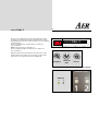
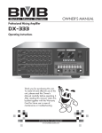
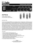
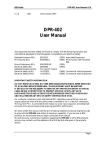
acoustiCube 3
Operating Instructions, version 1.0
1. Introduction
Contents:
1. Intoduction
1.a. Contents of Delivery
2.
Precautionary Measures
3.
Operating Elements
4. Operating Basics
4.1 Further Operating Elements
5.
Model Development
6.
Effect-Charts, 1 and 2
7.
Wiring Diagram
8.
Technical Data
9.
Signal Flow Diagram
10. AER Link-Function/Insert Point
Welcome to AER. Thank you for purchasing the acoustiCube 3
– without a doubt the benchmark among amplifying systems
for acoustic instruments (MIPA Award 2004 for Best Acoustic
Amp).
With version “3” we have made improvements to sound,
dynamics, presence, and natural sound. Not to mention
the features!
In essence – we have combined all the suggestions of Cube enthusiasts with all our knowledge and without compromise. The
result is the acoustiCube 3. Enjoy it!
New for version 3
•
•
•
•
•
•
•
•
Two identical channels
Bass-reflex cabinet separated from the electronics
New two-way speaker system
44V dynamic reserve in pre-amp EQ range
Separately adjustable and stabilised power source
Pre-amp matrix: three pre-amps, two phantom power,
combi-modus
32bit digital processor with USB-interface for parameter
adjustment manipulation
Aux in, mute, insert
It is not easy to write a manual. For those of you with some
knowledge of the technical matters addressed, much of what
is mentioned may be obvious. Nevertheless, we recommend
you take the time to read through the manual. That can help
us to identify and correct mistakes and ambiguities. The acoustiCube 3 is a very complex amplifier – yet simple in its basic
operation. This manual will be constantly updated. Please be
so kind as to contact us via email [email protected] so that
we can provide you with updates for as long as downloads
from the website are not available. Thank you!
1.a Contents of Delivery
Your acoustiCube 3 is complete if you find the following:
acoustiCube 3 with bag, power cable, footswitch Acousticube
IIa and 8-pole Din-footswitch cable
• USB-cable type A/B 3m
•
CD with setup, acoustiCube 3 control,
reset to factory settings
•
Manual acoustiCube 3
•
Manual acoustiCube 3 software
acoustiCube 3
-2-
C
2. Precautionary Measures
When using your acoustiCube 3, always take basic safety precautions to reduce the risk
of injury by fire or electric shock to a minimum.
Read all the directions in these operating instructions and
make sure that you understand them.
Pay attention to all warnings, instructions and supplementary
text written on the acoustiCube 3.
Always use a grounded mains connection with the appropriate
voltage supply. If you doubt whether the connection is grounded, have a qualified expert check it.
Please replace blown fuses only with those of the same type
and rating. Do not repair them!
When using your acoustiCube 3 always take basic safety precautions to reduce to a minimum the risk of injury by fire or electric shock.
Always operate your acoustiCube 3 in a safe place where no
one can trip over the cables to avoid accidents or damages.
Do not operate your acoustiCube 3 near devices with strong electromagnetic fields such as large mains transformers, generators, neon lights etc. Do not lay the signal cable parallel to
power lines.
Ensure that your acoustiCube 3 is switched off before plugging
the power cable into the mains.
Before cleaning your acoustiCube 3, unplug it from the mains
supply. Use a damp cleaning cloth. Do not use cleaning agents,
and be careful that no liquid finds its way into the amp.
There are no parts within your acoustiCube 3 that can be serviced by the user. Refer repairs and servicing to an agent authorised by AER.
Any unauthorised repair or servicing will invalidate the
two-year warranty!
Should 48/9V phantom power be needed, first establish the
proper cable connection (balanced cable or XLR plug or
6.3 mm stereo plug) and then switch on the amplifier. Otherwise the operating voltage will cause a short-circuit and endanger the functioning of your amplifier.
C
acoustiCube 3
-3-
3. Operating Elements
Channel 2 same as channel 1
Front side, module (from left to right):
input 2
clip
piezo
9V
48 V
mute
line
mic
e/p
clip
channel 1
piezo
9V
48 V
mute
line
mic
e/p
channel 2
program
mode
input 1
gain
pad
colour
bass
middle
treble
mute
mode
gain
colour
pad
Input 2
input channel 2
Input 1
input channel 1
LED chain
chain display for status and pre-amp choice
overload indicator
Mute
channel mute indicator
Piezo
sources with piezo level, instruments
with passive pick-up systems only
Line
sources with line-level,
instruments with active pre-amps and/or
magneticpickups
9V
phantom supply for line function
is switched on when mode switch is
pressed in line modus for three seconds
mic
sources with mic-level,
balanced and unbalanced
48V
phantom supply 48V for mic function
is switched on when mode switch is
pressed in mic modus for three seconds
E/P
Electret-microphone/Piezo pick-up
tip switch for input mode section
pad
switch to adjust input sensitivity
gain
input level control
colour
switch to activate mid-range contour filter
mute
mute control switch
Bass
tone control for bass
middle
tone control for mid-range
treble
tone control for treble
program
continuous program-selector encoder with
memory-function, internal effect
middle
treble
2. 1
acoustiCube 3
pre master master
return
channel
pan
mute
Clip
mode
bass
power
channel pan
effect panorama control
left: channel 1,
mid: channel 1+2,
right: channel 2
return
effect return control, adds internal effect
power
mains indicator
pre master
level control for L-out,
R-out and record ch1/ch 2 out
master
level control for the overal
C
-4-
acoustiCube 3
Rear Module (from left to right)
tuner
sub
L-out
record
ch1/ch2
presence
made in germany
send
DI
mic input
effect 2
notch
pan
ser/par
USB
s
p
phones
line
R-out
master
insert
aux in
aux
level
DI
level
di-pre post
effect
1=gnd 2=pos 3=neg
master ctrl.
return
return
Caution:
Risk of electric shock.
Do not open.
tuner
tuner output without tone control and effects
phones
stereo-headphone output including effects and
aux-in signal. Use stereo plugs only!
sub
6.3 mm jack as an output to drive an
active sub-bass, AER SUB 12/400A
line
output for active loudspeaker box including
tone control and effect, dependent on the master-control
send
output with EQ for external effect unit
L-out
line-out, adjustable via pre-master with tone
control, effect, stereo reproduction of external
effect and aux-in
pan
effect channel control for external effect (left:
channel 1, middle: channel 1 + 2, right: channel
2), internal effect
R-out
line-out, adjustable via pre master with tone
control, effect, stereo reproduction of external
effect and aux-in
return
stereo jack for external effect unit or other signal-source
ser/par
switch for serial or parallel effect mode
mic input
balanced and unbalanced, parallel with front
panel input 2
record ch1/ch2 stereo jack,
tip: channel 1 and
ring: channel 2, including tone control,
without effect, pre-master
master insert effect loop: input->return = ring / output ->
send = tip, for serial effect looping or connection of AER amps via link-function (chapter10)
aux in
cinch-input L/R for e.g. CD player
aux-return
aux-return-control, mixes the aux-in signal to
the overall signal
presence
presence-control, treble attenuation from 4kHz
di-level
DI-level-control, controls the level of the
DI-signal
di pre/post
DI-signal pre or post effect
di balanced
XLR-output, pre-master, no tone control
notch
notch-filter, center-frequency 120Hz, for
attenuation of feedback or instrument interference
USB
USB-port, connection of the AER DSPs with your
computer for changing the effect parameters
master ctrl.
Multipin-DIN-jack for connecting the AER
footswitch
effect 2 (external effect)
-5-
acoustiCube 3
Back Panel (left to right)
power
power jack with fuse holder
voltage selector
voltage selector switch 115/230V
ground lift
ground lift switch which disconnects signal
ground from protective conductor
speaker out
socket for passive bass box,
e.g. AER SUB 12/250P
Model:AcoustiCube 3
S/N: 040000097
230/115 V Fuse 3.15 A
0
4 0 0 0 0 0 9 7
6
C
C
acoustiCube 3
-6-
4. Operating Basics
zed. Then reduce the gain in order to create some headroom
(dynamic reserve) and determine the appropriate volume with
master control.
Starting up
Ensure that the mains voltage at your location corresponds
with what is permitted for operating your acoustiCube 3.
You will find the necessary information
on the rear sticker under "voltage”
(AC-voltage). Before starting the amp,
Model:AcoustiCube 3
S/N: 040000097
both master- and return-control should
230/115 V Fuse 3.15 A
be on zero position (as far as it will go
4 0 0 0 0 0 9 7 6
0
left) and all other control buttons
should be in mid position.
Then make all necessary cable connections (mains, instrument, microphone, or link). Now you can
switch on your
acoustiCube 3 with the power switch at the rear of the amp.
The green power lamp indicates that the amp is ready for
operation.
Choosing the best adjustment
Decide which input stage at your amp is the best for your
purpose:
piezo
line
9V
mic
48V
E/P
for passive pickup systems only
sources with line-level, instruments with active pre-amps and magnetic pickups
phantom-power for line sources (max. power
check technical data)
balanced microphone input. Rear XLR-input
mic input is parallel to input 2
phantom voltage supply for condenser microphone.
for simultaneous operation of a passive piezo
pickup and an electret microphone using a
3-pole instrument cable with stereo 6.3 mm
plug. Assignment: tip=piezo, ring=mic.
sleeve=ground
Use the mode button to choose the appropriate input stage. In
order to activate phantom power/voltage, press the button in
line or mic modus for three seconds and the appropriate phantom power/voltage will be switched on.
Level Control
Please check as follows:
Preconditions: Pad switch not in use, mute switch not in use;
preamp of the instrument (if present): EQ mid position, volume
open ca. 1/2 to 3/4.
Now set the pre master and master control at the
acoustiCube 3 in the zero position and increase the gain until
the clip indicator shortly flickers while playing powerfully. If
the gain adjusts itself ca.”9-11 o’clock”, you can be sure that
the source, e.g. your instrument + pickup
a) can completely level the Cube’s input stage and that
b) the overall background noise level (hiss, drone) is minimi-
The clip control generally indicates that the input signal is too
strong. In fact, changing the active tone control affects the clip
control. Short flickering is not dangerous. Still you should ensure that it stays that way. To be on the safe side, gain or volume of the source (instrument, microphone) should be slightly
reduced to guarantee perfect and distortion-free reproduction. If necessary you can mute the amp’s channel with the mute control. Mute can be operated via footswitch, but the effect
will be different (amp: ”hardwire”, footswitch: -40dB attenuation).
Advice / Problems:
Full drive can be achieved at a very low gain level. If the input
signal is too strong it can be reduced with the pad-switch: if
you do not succeed in making the input stage clip by turning
on full gain and full volume on the instrument, the source’s
signal is too weak. The audible result is not up to the performing standard of the acoustiCube. The background noise is
too loud and the chance for feedback increase.
Background Noise Analysis:
Leave the adjustments as they are and turn the gain at the
acoustiCube to the zero position. The only noise you will hear
now is that of the acoustiCube. Open the gain until the prior
position is reached, and then analyse how the background noise level changes.
Tone Control:
The acoustiCube’s three band tone controls are active and constructed to fulfil the specific requirements of both acoustic instruments and other sources. The colour switches activate a
mid-cut-treble-boost-filter that especially suits finger picking.
AER DSP 4 Digital Effect – internal effect
The acoustiCube 3 has a built-in (internal) digital 32bit AER-effect processor. With the effect–programme–endless-encoder
you can choose between 100 (0-99) effect programmes (factory
settings: chapter 6). The number of the chosen effect can be
seen in the two-digit display. The direction in which you turn
the control does not matter.
You can connect your acoustiCube with a computer via USB-cable, change the effect program parameters that suit your
requirements, make combinations and store them under a new
name. (See software handbook).
Two of the 100 effects can be stored and recalled via the AER
footswitch. You can select an effect and by pressing the programme-encoder on your acoustiCube this effect is stored. In
the display you will see one dot, right next to the first digit.
The first footswitch–memory–space is active. Selecting the second effect, the same procedure is followed. Now the display
shows two dots. The second footswitch–memory–space is active. The footswitch button "memory” allows switching between the two footswitch-memory-spaces.
acoustiCube 3
The dots in the display correspond to the indicators on the
footswitch. The channel-pan control determines the effect’s
spreading between the two channels. Please use the following
control positions:
As far as it will turn left: internal effect on channel 1,
not on channel 2
Middle: internal effect on channel 1+2
As far as it will turn right: internal effect on channel 2,
not on channel 1
C
-7-
2. 1
acoustiCube 3
acoustiCube 3 display
With the return level you determine the effect level of the
internal effect. If the effect is not necessary, set the return
level to the zero position (as far left as it will turn).
program
channel
pan
return
acoustiCube 3 effect section
Memory
1
2
Acousticube footswitch
C
-8-
acoustiCube 3
4.1 Further Operating Elements
Connections to module, rear (left to right, top to bottom)
tuner
sub
L-out
record
ch1/ch2
presence
made in germany
send
DI
mic input
effect 2
notch
pan
ser/par
USB
s
p
phones
line
R-out
master
insert
aux in
aux
level
DI
level
di-pre post
effect
At the tuner output, a line level is provided. You can connect a
tuner parallel to your instrument without having to reconnect
the instrument or connect the tuner into the signal path.
At the phones output a stereo headphone-amp with max.
2 x 100 mW / 32 Ohms provides you with monitoring possibilities. Here the direct signal of channel 1 and channel 2 are mono, but the effect parts are stereo. The master control serves as
volume control. The power amplifier and the loudspeaker are
not in operation.
The sub output is for the connection with the active auxiliary
AER bass-box SUB12/400A. A special filter system relieves the
loudspeaker system of the acoustiCube 3.
At line out the total output signal is located. Here you can
connect the active stereo extension AER CX8 and adjust the
final volume parallel with the master level.
L–out in connection with the R–out output as pre master total
outputs can be used
a) as parallel monitor paths or
b) for direct connection with an AER PA –system such as
AS281 or AS Q8 in combination with Sub 550D or CX8 in combination with SUB12/400 (pre master function see above).
Record ch 1/ ch 2 bears the unmixed signals of channel 1 + 2,
post EQ, without effect and pre master. Here you have access
to the unmixed channel signals, e.g. for recording purposes.
master insert The insert effect loop is input and output on a
stereo jack for serial looping of effects with
tip = send = output and ring = return = input.
You can also use it for:
1.
one additional line out
2.
the link between two or more AER amps with insert
function (AG8, acoustiCube or Compact Classic or
Domino)
1=gnd 2=pos 3=neg
master ctrl.
return
return
Caution:
Risk of electric shock.
Do not open.
For each function you will need the appropriate cable
connectors.
Example: As line output: stereo jack, tip + ring = hot, sleeve =
mass -> on mono jack.
For special AER link function, see the graphics in chapter 10.
The link function enables all the signals of the amplifiers
connected to be monitored on each amplifier even with different effect settings. The only restriction is that the levels are
interdependent. But in connection with an active speaker system (pre master function, see above) you have a complete
PA–system which can be easily handled from the stage.
At the aux in inputs left/ right you can connect a CD/ MD playback signal and mix it to the overall signal with the aux level
control. The signal is connected to phones as well as to
L- and R –out.
With the presence control you can influence the tone colour of
the acoustiCube 3 by damping the whole treble range above
4 kHz. Thus you have the possibillity of adjusting your
acoustiCube 3 easily for use with the different instruments
(e.g. violin, classical and steelstring guitar, harmonica, etc.).
As a factory setting, maximum treble reproduction and transparency were adjusted.
The electronic balanced XLR-output di is for the connection
with a mixing desk. Its output signal is the total output signal,
post-EQ. The di-pre post effect switch allows switching the
effects to the di signal. With the di level -control the output level can be adjusted to the mixing desk.
With the usb connection you can connect the acoustiCube 3
with your PC to change the effect parameters and design your
own effects. Please use the supplied USB A/B cable. For instructions please read the handbook Manual acoustiCube 3 Software.The master control socket is a DIN–multipin–socket.
Here you can connect the Acousticube footswitch with the supplied DIN–cable.
C
acoustiCube 3
-9-
That allows you to:
Switch between the two stored effects (memory 1, 2)
Switch on/ off the effect loops 1 + 2
Effect 1 (internal) on/ off: brief tapping
Effect 2 (external) on/ off: longer tapping
Please note:
The signal path is interrupted in the serial mode. If no accessory unit is connected, the signal cannot find its way into the
power amplifier, and you will hear nothing. This is not a malfunction but a misuse.
Connect volume pedals or footswitches to sockets ctr ch 1 and
ctr ch 2 to VCA level the volume of each channel or mute it
(e.g. in tuner mode) without affecting the sound.
When used in the serial mode,
the pan control should be set as follows: As far as it will turn
left:
effect on channel 1, not on channel 2
middle:
effect 2 on channel 1 and channel
As far as it will turn
right:
effect 2 on channel 2, not on channel 1.
When using a dual footwitch or a stereo volume pedal, a
single stereo connection with ctrl ch1 is sufficient.
effect 2
In addition, a further stereo effect unit, called
effect 2, can be connected. The send socket
needs to be connected to the input of the
effect unit.
That is it – have fun!
The return socket is stereo, and accepts both output-channels
of the effect unit.
An "insert” -cable might be required (see "Wiring-Diagram”).
The effect return and effect pan controls correspond to the
controls at the front (effect 1).
Please consider:
If you use a mono accessory unit, you would also use a mono
return-cable. The effect signal lies on the tip. The Acousticube
internally uses the left effect portion of effect 1 that also lies
on the tip.
Thus your mono accessory unit is linked with the acoustiCube,
but is only operative for the Acousticube. The signal is only
available at line (line out) and r–out when a special stereocable is used. The mono-signal of the accessory unit should lie
exclusively on the "ring” (middle ring) of the stereo jack (the
effect only works on the right side, therefore not on the acoustiCube, only on the accessory box CX8). But if you connect
"tip” and "ring” the mono-effect will spread to both sides (left
and right), that is to the acoustiCube as well as to the stereo
extension CX8.
The ser/par-switch switches effect 2 from serial to parallel mode, depending on whether the original signal is supposed to
pass through the effect completely (e.g. for EQ or compressor)
or whether it is separated.
AER GmbH und Co. KG.
D – 45665 Recklinghausen
Telephone: +49 (0)23 61–89 17 89 / -90
www.aer-amps.com
Copyright: AER, Recklinghausen
Telefax: +49 (0)2361 – 891791
AER assumes no liability for printing mistakes. Technical data is
subject to alteration after printing.
acoustiCube 3
5. Model Development
From 1992
Acousticube Prototype
From 1992
Acousticube I with ALESIS effect board
(16 effects)
1994
Revised model with 48V phantom power
from 12/1995
Change to Japan-FX-Board (ME-2)
with 16 effects
From 09/1996
AER Acousticube II with Japan-FX-Board
(ME-2/ME-32) New features: 100 effect
Three band tone controls
Connection for an active subwoofer
New power amplifier with output for an additional passive Box (SUB10)
From 04/1998
AER Acousticube IIa with Japan-FX-Board
(ME-32)
New features: Balanced piezo input stage
100 effects, two with memory function and
switchable via AER footswitch
Mute/ master control function via pedalconnection on AER footswitch
From 12/1998
New speaker system Beyma 8”BX/L
New power amplifier with two-step limiter
2000
New outfit with WB-spatter lacquer
From 04/2000
Revised effect chart: corrected assignment,
selectable phaser and combined effects
From 03/2002
AER Acousticube IIa with DSP3-FX-Board
(AER processing)
New features: Improvement of the effect
section’s audio quality
From 02/2003
Revised DSP3-firmware with combined
effects and further improved audio quality
From 07/2004
acoustiCube 3
-10-
C
C
-11-
acoustiCube 3
6. Effect-chart, 1
Reverb
Room
Room
Room
Room
Room
Room
Room
Room
Room
Room
Hall
Hall
Hall
Hall
Hall
Hall
Hall
Hall
Hall
Hall
Hall
Hall
Hall
Hall
Church
Church
Church
Church
Church
Church
Church
Church
Church
Church
Church
Church
Church
Church
Church
Church
Church
Cathedral
Cathedral
Cathedral
Cathedral
Cathedral
Cathedral
Pgr. No.
Grp. No. description
size / time
0
1
2
3
4
5
6
7
8
1
2
3
4
5
6
7
8
9
Dark
small
mid
Soft
small
mid
9
10
11
12
13
14
15
16
17
18
19
20
21
1
2
3
4
5
6
7
8
9
10
11
12
13
Dark
small
mid
Soft
small
mid
Vocal
short
mid
22
23
24
25
26
27
28
29
30
31
32
33
34
35
36
1
2
3
4
5
6
7
8
9
10
11
12
13
14
15
37
38
39
40
41
42
1
2
3
4
5
6
large
large
Bright
small
mid
large
large
large
Bright
Dark
Soft
long
very long
small
mid
large
small
mid
small
mid
large
Wood
Warm
Marble
small
mid
large
xlarge
large
xlarge
small
mid
large
xlarge
Dark
Warm
Marble
Dark
Warm
Marble
long
long
long
Ambience
Glass
Glass
Glass
Glass
Church
Church
Church
Warm
Warm
Warm
Warm
Dark
Bright
Bright
Bright
Bright
Pgr. No.
43
44
45
46
47
48
49
50
51
52
53
54
55
56
57
58
Grp. No. description
1
2
3
4
1
2
3
1
2
3
4
1
1
1
2
3
size / time
Room
Hall
Church
XLarge
small
mid
large
small
mid
large
xlarge
xlarge
xlarge
small
mid
large
C
-12-
acoustiCube 3
6. Effect-chart, 2
Special Acoustic Spaces & Outdoor Acoustic Spaces
Corridor
59
1 Warm
long
Corridor
60
2 Dark
long
Corridor
61
3 Bright
long
Swimming Pool
62
4
Railway Station
63
5
Housing Estate
64
6
Ambience
65
7 Open Air
Ambience
66
8 Piazza
Ambience
67
9 Forest
Ambience
68
10 Alpin
Delay
Soft reflection
Pan Delay
Pan Delay
Pan Delay
Pan Delay
Vocal
Vocal
Vocal
Vocal
Ambient Refelctions
Chorus
Silky
Warm
Deep
Mild
Frozen
Phasing Chorus
Flanger
Flanger
Flanger
Flanger
Flanger
Pgr. No. Grp. No. description size/time
69
70
71
72
73
74
75
76
77
78
1
2
3
4
5
6
7
8
9
10
Spacy Pan Delay
Fast Pan Delay
Pan Delay
long
xlong
mid
long
slapback
Pgr. No. Grp. No. description size/time
79
80
81
82
83
84
1 warm
2
3 bright
4 warm
5
6
fast
fast
slow
Pgr. No. Grp. No. description size/time
85
86
87
88
1
fast
2 metallic fast
3 silky
slow
4 spacy
warm
Combinations
Pgr. No. Grp. No. description size/time
Chorus Reverb
Chorus Reverb
Chorus Delay
Chorus Delay
Ambience Delay
Ambience Delay
Church Delay
Groovy delay
Stumbling reflections
Soft reflections -->
small church
Delay --> Small church
89
90
91
92
93
94
95
96
97
1
2
3
4
5
6
7
8
9
98
99
10
11
bright
bright
-13-
acoustiCube 3
C
7. Wiring Diagrams
shield
tip
Typical „Insert-lead“
e.g. Effect II-Return, Master-Ctrl.
ring
shield
sleeve
2
shield
balanced Mic.-lead
2
shield
unbalanced Mic.-lead
shield
Stereo-lead (balanced)
e.g. Footswitch
shield
Mono-lead (unbalanced)
e.g. Instrument
3
1
3
1
tip
ring
sleeve
tip
tip
ring
Special AER Insert Cable
(look at chapter 10)
ring
tip
C
-14-
acoustiCube 3
8. Technical Data
Channel 1/2
piezo
balanced/unbalanced
sensitivity
-26dBV, -11dBV with
pad switch
on
noise
< -82dBV
line/ep
unbalanced
sensitivity
-28dBV, -13dBV with
pad switch
on
Switchable 9V phantom power on
ring ( 2x100mA max)
noise
< -80dBV
mic
balanced
sensitivity
-38dBV
noise
< -80dBV
Switchable 48V phantom power
aux in
effect 2
clip indicator
L/R Cinch, unbalanced , 2x560mV
>5 k Ω (impedance depending on
"return" setting),
return Jack, stereo, unbalanced,
2x 750 mV, >5 k Ω (impedance
depending on "return" setting, left
channel on internal speaker
Headroom 6 dB
OUTPUT
tuner jack
1.3V, 100 Ω
phones jack
stereo, max. 1.7 V RMS,
max. 2x 100 mW into 32 Ω
For headphones only
Do not connect to other devices
Do not use mono plugs.
master control
8-pin DIN socket , for Acousticube IIa
footswitch, features:
Ch. 1/2
volume control / mute
(max –40dB gain reduction)
effects memory
1/2 toggle
effect 1/2
on/off
EQ Channel 1
bass
middle
treble
colour
±10 dB / 60 Hz
±6 dB / 600 Hz
±13 dB / 13 kHz
–3 dB bei 100 Hz, +6 dB bei 10 kHz
channel 2
bass
middle
treble
presence filter
±12 dB / 100 Hz
±12 dB / 1 kHz
±12 dB / 10 kHz
+0/–16 dB / 10 kHz
notch filter
-24 dB at 120 Hz BW-12 dB = 36 Hz
analog signal processing AER low-distortion limiter,
subsonic filter
built-in effects
AER 32-bit digital effects processor,
100 presets
power amp
120 W sine-wave into 8 Ω,
discrete bipolar transistor design
limiter
threshold 100 W
speaker system
2-way speaker
8" (20 cm)
low-midrang
Hexacone driver, Neodym magnet
1" (25 mm)
dome tweeter
Neodym magnet
mains power
AC 115/230 V (switchable),
50–60 Hz, max. 200 W
mains fuse
slow 3.15 A, 5x20 mm
cabinet
15 mm (0.59") birch plywood
Finish waterbased acrylic,
black spatter finish
dimensions
330 x 330 x 265 mm
(13"x13"x10.4") W x H x D
weight
13.00 kg (28,66 lbs)
di out XLR
adjustable 60-240 mV, 100 Ω,
balanced, pre/post effect
sub bass jack
max. 1.4V (post master),
100 Ω, with left channel of effects
Activates 200 Hz active crossover
for built-in speaker
line out jack
max. 1.4V (post master),
100 Ω, with right channel of effects
L out, R out jack
stereo effects, balanced
adjustable 0–1.4 V, 100 Ω,
Input and output voltages refer to 1 kHz sine-wave test signal.
Input voltages refer to 100 Watts output into 8 Ω.
record out
channel 1/2
Jack, 1.2V, 100 Ω
Piezo input sensitivities refer to 500 pF source capacitance and are given
as open-loop source voltages.
effect 2 send jack
max. 1.2V depending on
"pan" setting, 100 Ω
speaker out
subwoofer output
jack, max. 120 W into 8 Ω
Use only 8 Ω passive subwoofer
with built-in 200 Hz crossover
(AER Sub10/200P). Not suitable for
full-range external speaker.
Notes
Output voltages refer to 50 mV at channel 1, line input. Impedance
values for inputs and outputs are inner impedances (not source or load
impedances - except for power.
Noise measured at line output with
filter 22-22.000Hz, Gain at max. position, pad off, EQ flat, all returns at
min. position, input shorted, Master position refer to 100Watts output
into 8 Ohm ( 1.2V at sub bass )
Specifications and appearance subject to change without notice.
acoustiCube 3
9. Signal Flow Diagram, 1
-15-
C
acoustiCube 3
9.1. Signal Flow Diagram, 2
-16-
C
C
-17-
acoustiCube 3
10. Insert Point, AER Link-Function
amp 1
amp 2
amp 3
tip
ring
line out
tip
insert
ring
tip
tip
return
line out
send
insert
ring
L
external
effect
ring
tip
R
aux in
In case of occupied „return” socket, due to the
insert operating, you can still loop an external
effect, using the effect „send” and the „aux in”
sockets.
tip
return
l-out
r-out
link
link
pre master
amp 1
amp 2
amp 3