Download E3Switch DS3 Specifications
Transcript
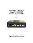
DS3/E3 over Ethernet
Pseudowire Gateway V5.4
November 11th, 2010
Operating Information
Legal Preface:
COPYRIGHT & TRADEMARKS
Copyright © 2007-2010 E3Switch LLC. All Rights Reserved.
All other product names mentioned in this manual may be trademarks or registered trademarks of their
respective companies.
LIMITED WARRANTY
E3Switch LLC (E3Switch) guarantees that every unit is free from physical defects in material and
workmanship under normal use for one year from the date of purchase, when used within the limits set forth
in the Specifications section of this User Guide. If the product proves defective during the warranty period,
contact E3Switch Technical Support in order to obtain a return authorization number. When returning a
product from outside of the United States of America, clearly state “NOT A SALE. RETURNED FOR
REPAIR” on the commercial invoice; and failing to do so, the customer will be responsible for imposed
duties and taxes. All customers are responsible for shipping and handling charges for returned items.
IN NO EVENT SHALL E3SWITCH'S LIABILITY EXCEED THE PRICE PAID FOR THE PRODUCT
FROM DIRECT, INDIRECT, SPECIAL, INCIDENTAL, OR CONSEQUENTIAL DAMAGES
WHATSOEVER (INCLUDING BUT NOT LIMITED TO LOST PROFITS) RESULTING FROM THE
USE OF THE PRODUCT OR ITS DOCUMENTATION, EVEN IF E3SWITCH HAS BEEN ADVISED
OF, KNOWN, OR SHOULD HAVE KNOWN, THE POSSIBILITY OF SUCH DAMAGES. E3Switch
makes no warranty or representation, expressed, implied, or statutory, with respect to its products or the
contents or use of this documentation and specifically disclaims its quality, performance, merchantability, or
fitness for any particular purpose. E3Switch reserves the right to revise or update its products or
documentation without obligation to notify any individual or entity. Please direct all inquiries to:
E3Switch LLC
80 Coronado Ave
San Carlos, CA 94070
U.S.A.
http://www.ds3switch.com, [email protected]
TEL: +1-650-598-0366
FCC STATEMENT
This device complies with Part 15 of the FCC Rules. Operation is subject to the following two conditions:
1. This device may not cause harmful interference.
2. This device must accept any interference received, including interference that may cause
undesired operation.
Note: This equipment has been tested and found to comply with the limits for a Class A digital device,
pursuant to Part 15 of the FCC Rules. These limits are designed to provide reasonable protection against
harmful interference when the equipment is operated in a commercial environment. This equipment
generates, uses, and can radiate radio frequency energy, and if it is not installed and used in accordance with
the instruction manual, it may cause harmful interference to radio communications. Operation of this
equipment in a residential area is likely to cause harmful interference, in which case the user will be
required to correct the interference at his own expense.
INDUSTRY CANADA NOTICE
This digital apparatus does not exceed the Class A limits for radio noise emissions from digital apparatus
set out in the Radio Interference Regulations of the Canadian Department of Communications.
Le present appareil numerique n'emet pas de bruits radioelectriques depassant les limites applicables aux
appareils numeriques de la class A prescrites dans le Reglement sur le brouillage radioelectrique edicte par
le ministere des Communications du Canada
EUROPEAN UNION (EU) STATEMENT
This product is in conformity with the protection requirements of EU Council Directive 89/336/EEC on the
approximation of the laws of the Member States relating to electromagnetic compatibility. The
manufacturer cannot accept responsibility for any failure to satisfy the protection requirements resulting
from a non-recommended modification of the product.
2
This product has been tested and found to comply with the limits for Class A Information Technology
Equipment according to CISPR 22/European Standard EN 55022. The limits for Class A equipment were
derived for commercial and industrial environments to provide reasonable protection against interference
with licensed communication equipment.
Attention:
This is a Class A product. In a domestic environment this product may cause radio interference in which
case the user may be required to take adequate measures.
International Electrotechnical Commission (IEC) Statement
3
TABLE OF CONTENTS
CHAPTER 1: DESCRIPTION AND REQUIREMENTS.....................................................................................................6
CHAPTER 2: QUICK SET-UP.................................................................................................................................7
CHAPTER 3: FRONT PANEL ..................................................................................................................................7
FRONT PANEL INDICATORS ...............................................................................................................................7
CHAPTER 4: REMOTE MANAGEMENT HTTP AND SNMP .....................................................................................8
UNIT'S IP/MAC ADDRESS...............................................................................................................................8
Automatic Link-Local IP Address.........................................................................................................8
Initial Numeric IP Address....................................................................................................................8
Unknown IP Address Recovery............................................................................................................8
MANAGEMENT PASSWORDS...............................................................................................................................9
SECURITY.......................................................................................................................................................9
HTTP Interface Security.......................................................................................................................9
SNMP Security......................................................................................................................................9
HTTP MANAGEMENT..................................................................................................................................10
Event Log File.....................................................................................................................................10
Resetting..............................................................................................................................................10
SNMP........................................................................................................................................................10
UPGRADING FIRMWARE..................................................................................................................................11
FEATURE ACTIVATION/UPGRADE.....................................................................................................................11
CHAPTER 5: OPERATING MODES AND CONFIGURATION ........................................................................................11
TELECOM.....................................................................................................................................................11
DS3 Circuit ID PMDL........................................................................................................................11
PACKET FLOW..............................................................................................................................................12
Packet Order........................................................................................................................................12
Receive Jitter Buffer Depth and Latency............................................................................................12
TDM Frames per Packet and Latency.................................................................................................12
PORT TO PORT PACKET FLOW.........................................................................................................................13
LAN-to-LAN.......................................................................................................................................13
Loopback.............................................................................................................................................13
LAN PORT SETTINGS....................................................................................................................................13
LAN Port Speed..................................................................................................................................13
Autonegotiation Problems...................................................................................................................13
SFP Second LAN Port........................................................................................................................14
Dedicated Management/Data LAN Ports............................................................................................14
VLAN........................................................................................................................................................14
PORT AUTO-DISABLE AND RETURN-TO-SERVICE DELAY....................................................................................14
DS3/E3 Return to Service delay..........................................................................................................14
LAN Auto-Disable..............................................................................................................................14
CHAPTER 6: INTEROPERABILITY.........................................................................................................................15
LAN..........................................................................................................................................................15
Autonegotiation problems...................................................................................................................15
SFP LAN Port 1..................................................................................................................................15
Pause Frames.......................................................................................................................................15
TELECOM.....................................................................................................................................................15
FIBER/COPPER MEDIA GATEWAYS...................................................................................................................15
CHAPTER 7: TELECOM CONNECTIONS.................................................................................................................16
FRAMING AND PHYSICAL LINK ........................................................................................................................16
TELECOM CABLING........................................................................................................................................16
CHAPTER 8: LAN CONNECTIONS AND PERFORMANCE .........................................................................................16
LAN PORTS................................................................................................................................................16
AUTONEGOTIATION........................................................................................................................................16
LAN CABLING.............................................................................................................................................17
LAN BUFFERING, LOADING AND FLOW CONTROL .............................................................................................17
4
CHAPTER 9: TDM LAN PACKET FORMAT ........................................................................................................17
GENERAL.....................................................................................................................................................17
TRANSPORT LAYER........................................................................................................................................17
CHAPTER 10: TROUBLESHOOTING.......................................................................................................................17
GENERAL.....................................................................................................................................................17
PERFORMANCE..............................................................................................................................................18
INTEROPERABILITY .........................................................................................................................................18
PINGING.......................................................................................................................................................18
STEP-BY-STEP DIAGNOSIS..............................................................................................................................18
CHAPTER 11: THIRD PARTY COPYRIGHT NOTICES ..............................................................................................19
ECOS LICENSE..............................................................................................................................................19
THE FREEBSD COPYRIGHT...........................................................................................................................19
THE NET-SNMP COPYRIGHT........................................................................................................................19
THE APACHE LICENSE ...................................................................................................................................21
THE SHA2 COPYRIGHT.................................................................................................................................22
THE BZIP2 LICENSE ....................................................................................................................................22
THE ATHTTPD LICENSE ..............................................................................................................................22
CHAPTER 12: TECHNICAL SPECIFICATIONS AND STANDARDS.................................................................................23
5
Chapter 1: Description and Requirements
Chapter 1: Description and Requirements
The E3Switch TDM-over-PSN pseudowire gateways described herein are used in pairs to extend a full or
fractional E3 or T3/DS3 TDM circuit over an intermediate Ethernet Layer-2 packet switched network
(PSN). The TDM circuit may be channelized or unchannelized and may contain framed or raw/encrypted
data. The gateway will regenerate the outgoing TDM clock and alarm conditions being received at the
remote end.
The LAN interface is RJ45 100/1000BaseTX copper or SFP 1000BaseX fiber optic. The two gateways
must have a LAN between them. Reverse topology, to bridge two LANs over an intermediate E3 or
T3/DS3 circuit, is not possible with this product; for that, please see our LAN Extender product line.
The gateways must be used in pairs. Single-ended operation for connection to a third-party TDMoPSN
gateway is not supported.
For ease of installation, the gateway requires minimal configuration, and, for full-rate E3/T3, will typically
work immediately upon connection of LAN and TDM cables.
The hot-swappable gateway card may be purchased in standalone or multi-card chassis and draws a minimal
6 watts of power. Standalone, single units ship in high-reliability, fan-free 1U chassis with rackmount
brackets and are available in a 100-240VAC or a ±35-75 volt DC models. NEBS-III, redundant-power
multicard chassis are available in 6-slot/1U and 20-slot/3U versions.
Both HTTP and SNMP management of the gateways is possible either in or out-of-band through either the
copper or SFP LAN port. An SFP transceiver is required to use the SFP LAN port.
Remote firmware upgrade to a gateway is possible through the LAN port, but may require a 15-second
outage during gateway reboot.
While the hardware for two TDM circuit connections is present on the unit, only one, bidirectional circuit is
currently supported.
The gateway will buffer data from the LAN to remove jitter, and implements quality-of-service mechanisms
to eliminate data loss. Packets received out-of-sequence will be properly reordered when possible. The
depth of the jitter buffer may be configured to achieve minimum latency. The number of bytes per packet is
configurable to allow balancing of bandwidth vs latency according to user's desire.
The gateway supports VLAN tagging, Type of Service (ToS) and DiffServ configuration.
A gateway's configuration must be manually set via the LAN port. The gateways do not currently autonegotiate parameters of the pseudowire connection.
The gateway has been designed with attention paid to minimum latency and minimal packet loss –
containing resequencing functionality that may not be present in other products. The gateway is often a
cost-effective and simpler alternative to a router. Even when connected to a LAN port on a router,
eliminating a router TDM card can free up expensive, limited, router backplane bandwidth .
The gateway is plug-and-play and can often be installed in several minutes. Network topologies and
configuration settings of equipment connected to the gateway can be complex, however, so additional time
should be allocated to achieve a properly functioning system.
6
Chapter 2: Quick Set-up
Chapter 2: Quick Set-up
Attach the gateway to a power source. The front panel lights should illuminate. Green is normal; orange
indicates an error.
Attach an Ethernet UTP5 cable from your LAN equipment to the RJ-45 LAN Port 2. The gateway can
perform automatic cross-over vs straight-through cable adaptation. The LAN 2 light will change from
orange to green if a properly negotiated link has been established. The network equipment attached to
the LAN port of the gateway should be set for autonegotiation mode in order to allow the gateway to
negotiate a 100Mbit full-duplex connection. Disabling autonegotiation or using old LAN equipment may
result in the attached LAN equipment configuring to half-duplex mode, resulting in CRC errors and packet
loss. Refer to the interoperability section of this document for more information
Attach two 75-ohm coaxial cables from the Port 2 BNC connectors of the gateway to the input and output
connectors of your E3 or DS3 link. Once the gateway is receiving a valid TDM signal, the DS3/E3 Port
LED will change from orange to alternating orange/green. The DS3/E3 Port LED will change to constant
green when a full, unerrored pseudowire connection has been established between the two gateways with no
TDM alarms at either end.
Further HTTP management of the gateway via LAN is required in the following situations:
● if using fractional rather than full-speed E3/T3
● if using unframed E3/T3
● if more than two E3Switch gateways exist on the LAN.
● to configure for minimal latency or maximum jitter tolerance
● to change the default administrator password. This is suggested, as configuration cannot be
modified after 5 minutes of any power cycle if the default password has not been changed.
There is no further required configuration for the gateway.
Chapter 3: Front Panel
Front Panel Indicators
All Indicators:
Green indicates normal operation.
Orange indicates an error condition.
Black indicates a disabled port.
DS3/E3 1/2:
Green if the unit has a bidirectional TDM circuit established with no alarm conditions.
Orange indicates an alarm or loss of the incoming TDM connection.
Flashes orange/green if incoming circuit is OK but an outgoing alarm condition is being transmitted.
BER:
Green if OK.
Orange flash for each BPV bit error.
Orange steady for absence of DS3/E3 receive signal, loss of frame lock onto receive bit-stream,
drive-level fault on transmit cable, or excessive receive bit errors.
LAN1/2:
Green when a properly negotiated 100/1000BaseTX Full-Duplex or SFP LAN connection exists.
Flashes black each time a packet is received on this port.
Orange indicates no valid connection.
7
Chapter 4: Remote Management HTTP and SNMP
Chapter 4: Remote Management HTTP and SNMP
Gateways contain both an HTTP management interface, which may be accessed via a web browser, and an
SNMPv2c agent.
Unit's IP/MAC Address
The source Ethernet MAC address of E3Switch gateways is 00:50:C2:6F:xx:xx. The gateway's current IP
and MAC addresses are always both shown at the HTTP management screen.
The gateway's management interface can be initially contacted at either its automatic link-local IP address
e3switch.local as described below or at its initial numeric IP address described below. Note that after initial
setup, an operator may have changed the contact IP address to a new value and the initial addresses below
may not work. Prior to operator reconfiguration the unit will respond to HTTP, SNMP and ping requests to
its initial IP address.
For initial communication with the gateway, it may be necessary to set the network address of the host port
communicating with the gateway to 169.254.xxx.xxx with subnet mask 255.255.0.0. Security protocols
advise routers not to forward packets with these link-local IP addresses, so a direct connection is advised.
Once initial contact has been established with the HTTP management interface of the gateway, the
gateway's IP address can be set to a new, static value if desired.
If a unit's operator-configured IP address is lost or forgotten, it can be recovered as described later in this
chapter.
Other than the e3switch.local addresses described below, all IP addresses used within the gateway's
management interface must be in xxx.xxx.xxx.xxx numeric format rather than a human-readable DNSresolvable hostname.
Automatic Link-Local IP Address
E3Switch products are shipped with an initial IP address that conforms to recent zero-configuration linklocal standards. This allows multiple E3Switch gateways on the same IP network to initialize with unique
IP addresses without conflict and allows simple ping/HTTP/SNMP access to the gateways using hostnames
e3switch.local or e3switch-2.local,... provided that, free, ZeroConf mDNS software has been installed on
the machine attempting to communicate with the gateway. Do not prefix www. prior to e3switch.local.
www.e3switch.local will not work.
If powered-up on a connected LAN, the gateways negotiate between themselves to determine which
gateway is assigned name e3switch.local and which receives e3switch-2.local and so on. Since the assigned
name will not necessarily be fixed to a particular gateway after power cycles, the system manager will
probably want to use/set the gateway's numeric IP address sometime during or after initial installation.
Web descriptions are available for ZeroConf mDNS and Link-local IPV4LL ip addresses. Free ZeroConf
software such as Bonjour for Windows or Avahi is available for Windows/Linux/Unix machines.
Initial Numeric IP Address
The gateway can also be contacted at its initial default IP numeric address which always takes the form
169.254.aa.bbb. Units typically have the initial IP address listed on top of the chassis or can be initially
contacted at the IP address above where aa.bbb matches the serial number listed on the front label.
The gateway's current IP and MAC addresses are both shown at the HTTP management screen.
Unknown IP Address Recovery
8
Chapter 4: Remote Management HTTP and SNMP
The following methods may be used to determine a gateway's IP address if lost or forgotten. Note that once
determined, management communication with the unit may only be possible from a host configured to the
same IP subnet address if the unit's default router address is invalid.
To manually discover a unit's IP address, unplug all LAN and BNC cables from the gateway and power
cycle the unit. 30 seconds after powerup, the gateway will begin blinking out its IP address on the leftmost
LED. Each digit is counted up as an orange blink with a pause between digits and a short blink for a 0. A
decimal in the IP address is indicated with a green blink. For example, <orange><orange><pause><shortorange><pause><green>... would be an IP address that begins “20.”
For those with access to packet sniffers, upon power-up, the gateway will broadcast several gratuitous ARP
packets on its network ports which can be examined with a sniffer or packet monitoring software to
determine a unit's IP address. The source Ethernet MAC address of such packets and E3Switch gateways is
00:50:C2:6F:xx:xx. Tcpdump or Wireshark are two readily available software packages to examine
network packets.
Additionally, examination of the MAC address table of an attached LAN switch or router may provide the
IP address if the E3Switch MAC address prefix (00:50:C2:6F:xx:xx) can be located.
Management Passwords
The HTTP management statistics page is initially accessible without a password. The HTTP settings page
is initially modifiable within the first several minutes after powerup with username admin and no password.
If the unit has not had its default password changed, after several minutes the settings page will be locked
for security reasons. It is desirable to change the default password of the unit. For security reasons,
changing the default password of the unit must be done within the first several minutes of any powerup. If
the HTTP management password is lost or forgotten, it may be reset by accessing the HTTP management
settings within the first minute after powerup and with no BNC cables attached to the unit.
SNMP statistics may initially be accessed using the read-only community name public. Write-community
names and variable access authorization may be set through the HTTP management interface.
Security
Please also refer to the password section above.
HTTP Interface Security
Access to the HTTP management interface statistics and settings pages can be selectively limited to users
knowing the HTTP management password, which is transmitted securely on the network using MD5
encoding. New values of management settings, or modifications of the administrator password are not
encrypted and are visible to users monitoring network packets, as is statistical data requested by an MD5
authorized user or any information visible on a HTTP page.
When logging out from any secure webpage, the browser window should always be closed! Browsers
typically continue to send administrator credentials continuously even after apparent logout.
SNMP Security
The gateway implements SNMPv2c, which is inherently an insecure protocol; however, the gateway
enhances security by implementing view-based access management (VACM), which can restrict read or
write access to specific management settings and statistics. When shipped, the gateway allows read access
to “safe” SNMP statistics and prohibits read and write access to statistics and settings which could allow
determination of network topology or interfere with normal link traffic. The VACM configuration can be
updated through the HTTP management interface to meet the user's needs, and most SNMP variables can
also be set through the HTTP management interface in a more secure manner than SNMP allows.
9
Chapter 4: Remote Management HTTP and SNMP
– SNMP VACM Security Warning –
As shipped, the default “safe_ro_view” is secure but not private.
View based access model VACM for SNMPv2c provides good restriction
of access to only specified statistics but no data privacy and
minimal user authentication. When a specific variable is enabled
for reading or writing, from a security perspective it should
be considered either public for reading or public for writing.
Alternatively, most configuration parameters can be set through
the HTTP password-protected interface which is secure.
Viewing snmpd.conf exposes it and community names to visibility by
3rd party network sniffers. All SNMPv2c data on the network
is visible. All community names can be "guessed" and, when used,
become visible to sniffers. Source IP addresses of requests
can be forged. Enabling a write community should be considered
insecure with respect to the specific view variables enabled.
Variables in the groups: interface, ds3, dot3 & mau, control the
link datapath; allowing write access allows disabling the link.
Specific variables disabled for all write users are secure.
Specific statistics disabled for all read users are invisible
and secure.
HTTP Management
The gateway contains a comprehensive, user-friendly HTTP management interface which allows a manager
to monitor bit-error-rates on the DS3/E3 link, lost packets, and user-friendly status messages at a single,
color-coded HTTP screen. A screenshot is available at www.e3switch.com. Most settings that can be
modified via SNMP can also be set through the HTTP interface in a more user-friendly manner.
Refer to the configuration section of this document for guidance on specific settings.
Event Log File
A timestamped log of operating status and events may be accessed at the HTTP management administration
page.
Resetting
Two options for resetting the gateway may be accomplished at the HTTP management administration page.
A management software reset will reset counters, statistics, MIB variables, and management software of the
gateway without interrupting data flow across the link. A hardware reset will temporarily interrupt link data
flow as if the gateway had experienced a power cycle. For new functionality to take effect, a hardware reset
is required after upgrading firmware but need not be initiated immediately. A software reset is not
appropriate after upgrading firmware, as only the management CPU would be reset while the packet transfer
CPU would be operating with the older, incompatible version of firmware.
SNMP
The gateway contains an SNMP agent which can respond to version 1 and version 2c requests for network
statistics from remote SNMP clients. The agent can also generate notifications of important network events
such as when network ports go up/down or experience high error rates. These trap notifications can be sent
to multiple hosts if desired, and using free or commercial software, the receiving hosts can log the
notifications or even generate email or pager messages for network managers.
SNMPv2c is inherently an insecure protocol, so the gateway implements VACM to restrict access to “safe”
statistics and settings. Please refer to the security discussion section of this document.
10
Chapter 4: Remote Management HTTP and SNMP
SNMP configuration of various parameters such as community names and trap destinations is accessed
through the HTTP management interface and is implemented as a configuration file having an snmpd.conf
structure. Snmpd.conf is described by third parties in publicly available documents.
Statistics and settings accessible via SNMP are called MIB-variables and are organized in a hierarchical
tree topology. The MIB variable trees implemented by the gateway include recent versions of the DS3/E3,
interface, MAU, dot3, and many of the typical IP-network MIB trees. The full list of MIB trees available is
listed by viewing the system.sysORTable of the gateway. As mentioned earlier, access to certain trees or
variables is initially disabled for security reasons, but can be set as the user wishes through the VACM
settings. The gateway can typically return 1000 MIB variables per second in bulk requests and support
SNMP response message sizes up to 5000 bytes.
Upgrading Firmware
For activation of additional capabilities of the gateway, see the “Feature Activation” section. Feature
upgrades do not necessarily require a firmware upgrade.
Firmware upgrades may be transferred to the gateway via the LAN port. A hardware reset, which will
interrupt link data flow for several seconds, will be required at some point after the transfer in order to
begin using the new firmware. Instructions for performing the TFTP transfer are included with all firmware
shipments. The most common source of problems when performing upgrades is attempting a TFTP transfer
in ASCII or text mode rather than binary or image mode.
Feature Activation/Upgrade
For activation of additional capabilities of the gateway after initial purchase, supply the factory with the
serial number from the front of your gateway (also shown at the HTTP management page for recent
firmware) and purchase an alphanumeric “factory upgrade key” which is entered at the HTTP management
screen.
Chapter 5: Operating Modes and Configuration
Telecom
There are four, low-level configuration settings for TDM ports; though, typically, the default settings are
appropriate:
● E3 vs DS3
● cable length (for long DS3 runs only)
● unframed or M13 vs C-Bit framing
● fractional or full-rate utilization
Use a “DS3” configuration setting for North America, Japan, and South Korea; otherwise, “E3” speed.
The cable length setting will transmit a slightly stronger signal on long DS3 coax runs. The M13/C-Bit
setting sets the AIC bit in DS3 frames to either 0 or 1. This bit is typically ignored by the DS3 carrier;
however DS3 carrier equipment set to autosense the incoming DS3 framing type will need this setting to be
correct.
DS3 Circuit ID PMDL
DS3 Path Maintenance Data Link (PMDL) identification messages associated with C-Bit framed DS3 links
may be received. Circuit ID messages convey human-readable, configurable, physical location information
of the DS3 source equipment. PMDL Circuit ID messages facilitate confirmation of the data source when
presented with a pair of unlabeled BNC cables.
11
Chapter 5: Operating Modes and Configuration
Packet Flow
Packet Order
802.1p Class of Service (CoS), and DiffServ when appropriate, levels are configurable to ensure timely
delivery of TDM packets through the LAN.
While traveling across packet switched networks, received packets may arrive out of sequence for a variety
of reasons. E3Switch gateways will use sequence numbers, present in the packets, to restore original packet
order.
Receive Jitter Buffer Depth and Latency
While traveling across packet switched networks, received packets may exhibit slight variations in traversal
time. The function of the configured receive-buffer-depth is to absorb this jitter and ensure that there is
always data available to present to the outgoing, constant-bit-rate, TDM circuit when an incoming LAN
packet is delayed. Larger configured buffer depths result in greater latency, so it is desirable to determine
the minimum required value for this setting. The amount of LAN packet jitter in the system can be
determined at the HTTP web management status page by examining the “Min⁄Cur⁄Max Pkts Waiting” and
“Jitter Buffer Underflow” counters. The “Jitter Buffer Depth” value should be adjusted at the HTTP web
management settings page until no “Jitter Buffer Underflow” errors accumulate and the “Min Pkts Waiting”
level is at least one. The typical latency incurred per, 1000-byte, LAN packet of jitter buffer depth in a fullrate TDM circuit is 0.2ms. Configuring a, rather deep, 5-packet buffer would introduce 1ms of delay into
the system. For fractional TDM circuits with large TDM Frames per Packet settings described below, the
latency introduced is the product of the “Jitter Buffer Depth” and the latency per LAN packet, which can
become too large if care is not taken.
TDM Frames per Packet and Latency
For the following discussion, if the incoming TDM is unframed, the term “frame” simply refers to the
number of TDM bits that would constitute a frame if framing were in effect.
Each LAN packet requires approximately 50-bytes of overhead for transmission. Accordingly, on limited
bandwidth LANs, it is desirable to consolidate as many complete, TDM frames as possible into each LAN
packet. At full T3 TDM speed, this results in two frames per packet and a latency of approximately 0.2ms.
At full E3 speed, this results in seven frames per packet and a latency of approximately 0.3ms.
When fractional TDM is in effect, as little as 4-bytes per frame may be in use. In this case, transmitting
only two frames per LAN packet would still result in a 0.2ms latency, while waiting for each TDM frame to
arrive; however, only 8 bytes of each 64-byte minimum LAN packet, and thus 13% of the required LAN
bandwidth, would be in use for actual TDM data. This efficiency level may be too low in limitedbandwidth applications such as satellite links. Increasing the number of frames per packets in this case will
increase the efficiency of the transmission but at a cost of approximately 0.1ms latency per T3 frame or
0.05ms latency per E3 frame.
Latency in milliseconds is approximately equal to 1000 x [frames per LAN packet] x [bits per full TDM
frame] / [full TDM bitrate] – where [bits per full TDM frame] is 4760 for T3 and 1536 for E3; full TDM
bitrate is 44,736,000 for T3 and 33,368,000 for E3. To achieve 97% efficiency of a 10Mbit/s satellite link
in a fractional E3 environment, 9.7Mbit/s of E3 data / 33.368Mbit full E3 rate x 1536 = 446 bits / 8 = 55
bytes per E3 frame in use, allowing about 26 frames per LAN packet. The latency incurred if this
maximum efficiency packing were in use would be 1000 x 26 x 1536 / 33,368,000 = 1.2ms. This singlepacket latency must now be multiplied by the typical or maximum jitter buffer depth described in the prior
section of this document to estimate the entire latency of the system.
12
Chapter 5: Operating Modes and Configuration
Port to Port Packet Flow
LAN-to-LAN
Full LAN-to-LAN packet flow can be enabled on a unit, if desired. This might be useful if it was desirable
for incoming SFP management packets to exit the copper LAN Port 2 of the unit, along with the packets
carrying TDM data, in order to reach and manage the remote gateway. LAN-to-LAN unidirectional flow
for monitoring may also be configured if desired.
LAN-to-LAN should be used cautiously in combination with management or data-only LAN port settings.
The blocking of a subset of traffic can result in network and spanning tree topologies which can be
inappropriate or difficult to diagnose.
Loopback
C-Bit T3 TDM ports will respond to FEAC loopback requests. A TDM port can also be put into loopback
via appropriate DS3-MIB SNMP commands.
LAN Port Settings
The hardware for two LAN ports exist on all gateways shipped; however, entry-level models ship with only
100Base-TX mode on LAN Port 2 enabled. See upgrades section of this manual to enable these additional
features if required:.
●
●
GbE, GigE 1000Base-T for the RJ-45 LAN Port 2
jumbo frames (9600 bytes)
See the “Interoperability” section of this manual for information on packet lengths and detailed port
connection/autonegotiation discussion.
The autonegotiation mode of the gateway must match the autonegotiation mode of attached LAN
equipment. If autonegotiation is enabled on the gateway it must be enabled on the attached equipment. If
disabled on the gateway, it must be disabled on the attached equipment. This requirement is necessary to
fulfill 802.3 standards which mandate a fallback to half-duplex operation if an autonegotiation mismatch
exists. The gateways require full duplex LAN connections to operate.
LAN Port Speed
1000Mbit/s LAN speeds are only available via the SFP port or if GbE LAN has been purchased.
100Mbit/s is generally preferred over 1000Mbit/s, which generates significantly more power-requirements,
heat, and radiated noise even in the absence of packet flow. 1000Mbit/s may slightly reduce path latency,
as an incoming LAN packet must be fully received before being forwarded to an outgoing port. The latency
savings to receive or transmit a 1500-byte packet at 1000Mbit/s vs 100Mbit/s speed is 0.108 milliseconds
(1500bytes/packet x 8bits/byte / (100Mbits/s) - 1500bytes/packet x 8bits/byte / (1000Mbits/s)).
Setting more than one LAN port to 1000Mbit/s is not recommended and may result in
underflow/overflow errors in certain high packet load, memory-intensive cases.
Autonegotiation Problems
There are rare cases with older LAN equipment in which it may be necessary to disable autonegotiation. If
CRC-errors or short packet errors are seen in the management statistics of the LAN port, the attached LAN
equipment has probably configured itself to half-duplex mode and colliding packets are being lost. In such
a case, autonegotiation should be disabled on both the gateway and the attached LAN equipment, with both
forced to 100BaseTX full-duplex. Autonegotiation interoperability and standards were not well understood
by the industry at the inception of 100BaseTX, resulting in some older LAN equipment not understanding
the gateway's autonegotiation advertisement of strictly full-duplex capability.
13
Chapter 5: Operating Modes and Configuration
SFP Second LAN Port
The SFP LAN Port 1 hardware exists on all gateways shipped and allows an SFP transceiver to enable outof-band management, through either LAN port, or fiber-optic LAN connections of 10km or more. Refer to
interoperability section of this document for compatible SFP transceivers.
Dedicated Management/Data LAN Ports
If the SFP Second LAN Port is in use, then either LAN port may be configured to pass TDM data packets
or, selectively, to pass only management or only TDM data packets when such can be determined.
LAN-to-LAN forwarding should be used cautiously in combination with management or data-only LAN
port settings. The blocking of a subset of traffic can result in network and spanning tree topologies which
can be inappropriate or difficult to diagnose.
If a LAN port is configured for TDM data-only packets, the unit will drop incoming management packets
destined for an E3Switch MAC address. This provides a moderate level of security. On a “data-only” LAN
port, these management unicast packets and management broadcast/multicast packets may not be
forwarded to the second LAN even if LAN-to-LAN traffic flow is configured.
VLAN
In some firmware versions it is possible to configure a VLAN ID for packets containing TDM data.
VLAN configuration settings shown at the HTTP management page may also be set for communication
with the gateway's management entity.
As shipped, the unit will accept management packets with any VLAN tags and attempt to respond to the
same. For more robust performance, specific VLAN tag settings can be configured.
Port Auto-Disable and Return-to-Service Delay
In addition to manually configuring a port as disabled, the gateway has the ability to delay a DS3/E3 port's
return to service for a specified period of time after it has failed or disable a LAN port if both TDM circuits
are down.
DS3/E3 Return to Service delay
The return-to-service delay prevents network topology thrashing if a TDM circuit is flapping up and down.
Some TDM carriers will interrupt service for 50msec, once per day as a link test. A configurable, failuretime setting exists to prevent such tests from triggering a link-down, retun-to-service delay.
To exit the return-to-service delay, power-cycle the gateway or click the button which appears on the
configuration HTTP screen of a gateway that is in configuration delay.
LAN Auto-Disable
The LAN port can be configured to automatically disable itself when no TDM circuit exists. This setting is
useful for attached LAN equipment which requires the LAN port to go down in order to understand that the
path to the remote network is no longer available. Use this setting cautiously, as management of the
gateway will also no longer be possible through a disabled LAN port.
To exit the LAN-port-disabled condition, power-cycle the gateway, which will allow communication with
the gateway for approximately one minute even if TDM ports are down.
14
Chapter 5: Operating Modes and Configuration
Chapter 6: Interoperability
LAN
The LAN ports of the gateway support, at a minimum, all 100BaseTX Full-Duplex Ethernet connections up
to maximum line lengths and are set to auto-MDI/MDIX to automatically detect/correct crossover vs
straight LAN cable and autonegotiate for full-duplex and pause frame modes with the attached LAN
equipment. Passwords may be purchased to upgrade to enhanced LAN port modes as described elsewhere
in this manual.
The gateway will pass all unerrored packets which do not exceed 1650 bytes in packet length (9600 with
jumbo frames enabled). This length allows QinQ, stacked VLAN, and extended packet-length router
protocols to be passed without concern. The management agent accepts and responds with packets having
MTU of 1350 bytes in order to automatically allow room for security protocol overheads.
Autonegotiation problems
There are rare cases with older LAN equipment in which it may be necessary to disable autonegotiation. If
CRC-errors or short packet errors are seen in the management statistics of the LAN port, the attached LAN
equipment has probably configured itself to half-duplex mode and colliding packets are being lost. In such
a case, autonegotiation should be disabled on both the gateway and the attached LAN equipment with both
forced to 100BaseTX full-duplex. Autonegotiation interoperability and standards were not well understood
by the industry at the inception of 100BaseTX, resulting in some older LAN equipment not understanding
the gateway's autonegotiation advertisement of strictly full-duplex capability.
It is highly desirable to leave autonegotiation enabled so that changing attached LAN equipment does not
result in the new equipment defaulting to half-duplex if set to autonegotiate.
SFP LAN Port 1
This port is designed to be compatible with inexpensive, high-quality, copper or fiber-optic, SFP
transceivers from Finisar, which allows LAN connections of 10km or more. Most other industry-standard
SFP transceivers will work as well; however, fiber-optic features such as temperature and optical
transmit/receive power and alarms will only be available if using Finisar transceivers. Non-Finisar copper,
RJ45 SFP transceivers may only operate in 1000Base-T mode, while recommended transceivers from
Finisar, and possibly Avago or 3Com will operate in 100Base-TX mode as well.
Pause Frames
The gateway generates no pause frames and ignores pause command frames sent to it.
Telecom
The gateway can transmit over a variety of E3 or T3/DS3 links (with appropriate media gateways) such as
fiber optic, microwave radio, laser, copper, satellite, or a combination; however, the attachment interface is
always via 75-ohm copper coaxial rather than optical. The TDM circuit may be either framed or unframed
and supports both M13, M23, clear-channel, C-Bit, and G.751 framing. C-Bit framing is suggested for DS3
links.
Fiber/Copper Media Gateways
Transition Networks DS3/E3 Coax to Fiber Media Gateway, SCSCF3014-100 has been reported to lack the
ability to properly maintain separate DS3/E3 transmit clock speeds in each direction and are not
recommended. This problem typically manifests itself as frame slips or loss of TDM signal lock in one
15
Chapter 6: Interoperability
direction at a rapid, consistent periodic rate, which is proportional to the difference in clock speeds of each
TDM direction.
Chapter 7: Telecom Connections
Framing and Physical Link
The gateway can transmit the LAN data over a variety of E3, T3/DS3 links (with the appropriate media
gateway) such as fiber optic, microwave radio, laser, copper, satellite, or a combination. The gateway may
be used with a standard (i.e., M13, M23, clear-channel, C-Bit or G.751) framed or unframed, fractional or
full-rate E3 or T3/DS3 link with AMI and HDB3 or B3ZS encoding. C-Bit framing is recommended for
DS3 links. The gateway will report PMDL Circuit ID present on C-Bit links.
Each gateway regenerates the timing clock of the remote, received TDM bit-stream, within E3 and T3/DS3
standards. The receive and transmit clock rates are displayed at the unit's HTTP management page.
Telecom Cabling
For the E3 or T3/DS3 connection, two 75-ohm coaxial cables (one transmit and one receive) with BNC
connectors are required at each end. It is important that 75-ohm cable be used and not 50-ohm cable. For
long connections or in electrically noisy environments it may be important to use a high-quality 75-ohm
cable which will have more consistent shielding and conduction. The maximum length of each cable shall
be 440 meters for E3 or 300 meters for T3/DS3, but the acceptable cable lengths of equipment attached to
the gateway must be met as well. For lengths over 135 meters, testing in field should be used to determine
whether bit error rates are acceptable. Long cable lengths also require careful selection of cable type and
attention to sources of external noise.
Third-party fiber to copper media gateways can be used with the E3Switch gateway to implement fiberoptic DS3/E3 links; however, refer to the interoperability section of this document for vendors to avoid.
Chapter 8: LAN Connections and Performance
LAN Ports
Each LAN port implements the following features to maximize LAN compatibility and link utilization and
minimize packet loss:
• autosense/autoconfiguration/autonegotiation with the attached LAN.
• 100Mbit/sec data rates (1000Mbit/s via SFP or if GbE upgrade purchased).
• full-duplex LAN connection.
• data buffering.
• 1650-byte packet acceptance (1350 for mgmt and 9600 for jumbo).
These features and their ramifications are discussed below in more detail.
Autonegotiation
The network equipment attached to the LAN port of the gateway should be set for autonegotiation
mode in order to allow the gateway to negotiate a 100Mbit full-duplex connection.
There are rare cases with older LAN equipment in which it may be necessary to disable autonegotiation. If
CRC-errors or short packet errors are seen in the management statistics of the LAN port, the attached LAN
equipment has probably configured itself to half-duplex mode and colliding packets are being lost. In such
a case, autonegotiation should be disabled on both the gateway and the attached LAN equipment, with both
forced to 100BaseTX full-duplex. Autonegotiation interoperability and standards were not well understood
16
Chapter 8: LAN Connections and Performance
by the industry at the inception of 100BaseTX, resulting in some older LAN equipment not understanding
the gateway's autonegotiation advertisement of strictly full-duplex capability.
It is highly desirable to leave autonegotiation enabled so that changing attached LAN equipment does not
result in the new equipment defaulting to half-duplex if set to autonegotiate. Autonegotiation must always
be enabled for 1000Mbit/s links.
LAN Cabling
It is important to use the correct cabling for proper operation. Use UTP Category 5 network cable with RJ45 connectors for the LAN ports, and do not exceed 100 meters (328 feet) in length. Either a straightthrough or crossover cable may be used.
LAN Buffering, Loading and Flow Control
This gateway contains approximately 500kBytes of total packet buffer. Queue utilization can be monitored
at the gateway's statistics HTTP page, and buffer overflow will appear as “Rx oflow” errors at the same
HTTP page.
Chapter 9: TDM LAN Packet Format
General
A variety of different headers may be configured on the LAN packets that transport TDM data. The header
format must be manually specified. The gateways do not currently negotiate with each other to determine
packet format. The header format must be identical for each pair of connected gateways. Either
SAToP or CESoTDM protocols may be selected depending upon whether full-rate or fractional TDM is
desired.
Transport Layer
Depending upon the model purchased, LAN packets may be configured with simple MAC Layer 2
addressing or more sophisticated IP/UDP or MPLS headers.
Chapter 10: Troubleshooting
General
A great deal of diagnostic information is available by accessing the HTTP management interface of the
gateway. Refer to the management section of this document for additional information.
The gateway's front panel lights can provide useful information but are often under-utilized. They are
simple to read and can indicate where a data connection is being lost. It can be very helpful to learn their
meaning and monitor flashes as a packet is received at each port.
Incoming Circuit ID is shown at the top of the gateway's HTTP management page for C-Bit DS3 links,
facilitating confirmation of the remote data transmitter when presented with a pair of unlabeled BNC cables.
The Ethernet networks to which the gateway connects are complex and may contain thousands of devices,
each of which requires proper configuration and performance. As such, network configuration and
topology issues dominate when problems arise. When troubleshooting, solutions can be reached more
rapidly by remembering that the most frequent cause of problems arises from improper network
configurations.
The next most frequent source of problems generally arises from faulty cabling or connectors or incorrect
cable type. Cabling must be UTP5 or better for LAN and 75-Ohm rather than 50-Ohm for TDM. If long
TDM cable runs or an electrically noisy environment exists, high-quality coaxial cable will be required.
17
Chapter 10: Troubleshooting
The least frequent cause of problems will be the hardware of the gateway itself. This statement is not due to
a narcissistic point of view, but rather to the simplicity of configuration features on the gateway and the
low-component count. A microwave radio link, for example, has waveguides that can fill with water,
antennas that can become misaligned, foreign objects that can block the path. From a failure point of view,
the gateway is a simpler device.
Performance
Performance issues are addressed in the prior chapters.
Interoperability
The interoperability section of this manual should be reviewed to ensure that appropriate equipment is
connected to the gateway. Connected LAN equipment should adhere to 802.3 standards.
Pinging
Ping is not reliable. The protocol which ping programs use does not guarantee delivery of the data
packets. Ping programs from major software and hardware corporations are known to contain bugs,
both in packet content and function. Generally, however, nearly all of the ping packets on a test network
that is not over-loaded should get through; if fewer are received, there is probably a problem.
The ping program is a useful, simple test for a TCP/IP Ethernet network. It is a program that sends a data
packet from a source machine to a destination machine, which then returns a response packet. There is a
plethora of information about ping and the free public-domain ping utilities available. Ping is often
supplied as a standard operating system utility, and often the command “ping” followed by the destination
machine's IP address or hostname is all that is required to be typed at the source machine's command line.
The default ping generates approximately one 64-byte packet per second. This is not a robust test. If
convenient, locate a ping program or set command line parameters to generate perhaps 50 pings per second
and try both small packets and large 1400-byte packets. Be aware that packets larger than 1400 bytes
sometimes uncover bugs in the software of ping programs.
Step-by-Step Diagnosis
This section assumes that communication between two machines at opposite ends of the E3, T3/DS3 link
(herein the link) is failing. If this is a test in the laboratory or without a TDM circuit present, be sure to read
the previous “Laboratory Testing” section first.
1.
If access to the HTTP management interface of the gateway is possible, many useful status messages
will be displayed. Typically, any message highlighted in orange should be of concern. Error counters
are of lesser concern if they are not incrementing, and some link errors would be normal as link cables
are initially connected.
2.
The DS3/E3 BER light of the gateway should be illuminated and green. This indicates that a valid,
DS3/E3 waveshape is being received without bit errors and with proper framing. Refer to the front
panel section of this document for other light colors.
The DS3/E3 port light of the gateway should be illuminated and green. This indicates that a valid,
framed carrier signal is being received from a remote E3Switch gateway. Refer to the front panel
section of this document for other light colors.
If flashing orange/black, the link is in a configured return-to-service delay mode as discussed
elsewhere.
18
Chapter 10: Troubleshooting
3.
Ensure a proper LAN cable is being used. Straight-through or crossover cabling is acceptable. The
LAN light of the gateway port to which any LAN is attached should be illuminated and green. If not,
ensure that the attached equipment is set for autonegotiation and can accept 100BaseTX Full-Duplex
links. Refer to front panel section of this document for other LAN light colors.
4.
The network equipment attached to the LAN port of the gateway should be set for autonegotiation
mode in order to allow the gateway to negotiate a 100Mbit full-duplex connection. Forcing either the
gateway's or attached equipment's LAN port to 100Mbit full-duplex may not allow the proper
autonegotiation and LAN connection to occur. There are rare cases with older LAN equipment in
which it may be necessary to disable autonegotiation. If CRC-errors or short packet errors are seen
in the management statistics of the LAN port, the attached LAN equipment has probably
configured itself to half-duplex mode and colliding packets are being lost. In such a case,
autonegotiation should be disabled on both the gateway and the attached LAN equipment with both
forced to 100BaseTX full-duplex. Autonegotiation interoperability and standards were not well
understood by the industry at the inception of 100BaseTX, resulting in some older LAN equipment not
understanding the gateway's autonegotiation advertisement of strictly full-duplex capability.
5.
Monitor lights during packet transmission:
• With LANs attached, verify, perhaps using pings, that data packets generated by a local machine
cause the gateway's light of the connected LAN port to blink. If not, determine if there is an
intermediate router or piece of equipment that is not properly forwarding the data packets to the
gateway. Examine the Link/Activity light on the source machine and any intermediate machines to
ensure they behave properly (usually flicker) as well.
6.
Enlist the aid of a sniffer program to view at the source and destination machines exactly what data
packets are being sent and received. Free public-domain programs such as Wireshark are readily
available.
Chapter 11: Third Party Copyright Notices
E3Switch is grateful for and contributes to open source software development which may be protected by
the following copyright notices and license terms:
eCos License
E3Switch gratefully acknowledges the contributions of the eCos developers and community. Current eCos source files are available at http://ecos.sourceware.org/ E3Switch
implementation-specific modifications to those files are available by contacting E3Switch LLC.
The FreeBSD Copyright
Copyright 1994-2006 The FreeBSD Project. All rights reserved.
Redistribution and use in source and binary forms, with or without modification, are permitted provided that the following conditions are met:
1. Redistributions of source code must retain the above copyright notice, this list of conditions and the following disclaimer.
2. Redistributions in binary form must reproduce the above copyright notice, this list of conditions and the following disclaimer in the documentation and/or other materials
provided with the distribution.
THIS SOFTWARE IS PROVIDED BY THE FREEBSD PROJECT ``AS IS'' AND ANY EXPRESS OR IMPLIED WARRANTIES, INCLUDING, BUT NOT LIMITED TO,
THE IMPLIED WARRANTIES OF MERCHANTABILITY AND FITNESS FOR A PARTICULAR PURPOSE ARE DISCLAIMED. IN NO EVENT SHALL THE FREEBSD
PROJECT OR CONTRIBUTORS BE LIABLE FOR ANY DIRECT, INDIRECT, INCIDENTAL, SPECIAL, EXEMPLARY, OR CONSEQUENTIAL DAMAGES
(INCLUDING, BUT NOT LIMITED TO, PROCUREMENT OF SUBSTITUTE GOODS OR SERVICES; LOSS OF USE, DATA, OR PROFITS; OR BUSINESS
INTERRUPTION) HOWEVER CAUSED AND ON ANY THEORY OF LIABILITY, WHETHER IN CONTRACT, STRICT LIABILITY, OR TORT (INCLUDING
NEGLIGENCE OR OTHERWISE) ARISING IN ANY WAY OUT OF THE USE OF THIS SOFTWARE, EVEN IF ADVISED OF THE POSSIBILITY OF SUCH DAMAGE.
The views and conclusions contained in the software and documentation are those of the authors and should not be interpreted as representing official policies, either expressed or
implied, of the FreeBSD Project.
The Net-SNMP Copyright
---- Part 1: CMU/UCD copyright notice: (BSD like) ----Copyright 1989, 1991, 1992 by Carnegie Mellon University
Derivative Work - 1996, 1998-2000
Copyright 1996, 1998-2000 The Regents of the University of California
19
Chapter 11: Third Party Copyright Notices
All Rights Reserved
Permission to use, copy, modify and distribute this software and its
documentation for any purpose and without fee is hereby granted,
provided that the above copyright notice appears in all copies and
that both that copyright notice and this permission notice appear in
supporting documentation, and that the name of CMU and The Regents of
the University of California not be used in advertising or publicity
pertaining to distribution of the software without specific written
permission.
CMU AND THE REGENTS OF THE UNIVERSITY OF CALIFORNIA DISCLAIM ALL
WARRANTIES WITH REGARD TO THIS SOFTWARE, INCLUDING ALL IMPLIED
WARRANTIES OF MERCHANTABILITY AND FITNESS. IN NO EVENT SHALL CMU OR
THE REGENTS OF THE UNIVERSITY OF CALIFORNIA BE LIABLE FOR ANY SPECIAL,
INDIRECT OR CONSEQUENTIAL DAMAGES OR ANY DAMAGES WHATSOEVER RESULTING
FROM THE LOSS OF USE, DATA OR PROFITS, WHETHER IN AN ACTION OF
CONTRACT, NEGLIGENCE OR OTHER TORTIOUS ACTION, ARISING OUT OF OR IN
CONNECTION WITH THE USE OR PERFORMANCE OF THIS SOFTWARE.
---- Part 2: Networks Associates Technology, Inc copyright notice (BSD) ----Copyright (c) 2001-2003, Networks Associates Technology, Inc
All rights reserved.
Redistribution and use in source and binary forms, with or without
modification, are permitted provided that the following conditions are met:
* Redistributions of source code must retain the above copyright notice,
this list of conditions and the following disclaimer.
* Redistributions in binary form must reproduce the above copyright
notice, this list of conditions and the following disclaimer in the
documentation and/or other materials provided with the distribution.
* Neither the name of the Networks Associates Technology, Inc nor the
names of its contributors may be used to endorse or promote
products derived from this software without specific prior written
permission.
THIS SOFTWARE IS PROVIDED BY THE COPYRIGHT HOLDERS AND CONTRIBUTORS ``AS
IS'' AND ANY EXPRESS OR IMPLIED WARRANTIES, INCLUDING, BUT NOT LIMITED TO,
THE IMPLIED WARRANTIES OF MERCHANTABILITY AND FITNESS FOR A PARTICULAR
PURPOSE ARE DISCLAIMED. IN NO EVENT SHALL THE COPYRIGHT HOLDERS OR
CONTRIBUTORS BE LIABLE FOR ANY DIRECT, INDIRECT, INCIDENTAL, SPECIAL,
EXEMPLARY, OR CONSEQUENTIAL DAMAGES (INCLUDING, BUT NOT LIMITED TO,
PROCUREMENT OF SUBSTITUTE GOODS OR SERVICES; LOSS OF USE, DATA, OR PROFITS;
OR BUSINESS INTERRUPTION) HOWEVER CAUSED AND ON ANY THEORY OF LIABILITY,
WHETHER IN CONTRACT, STRICT LIABILITY, OR TORT (INCLUDING NEGLIGENCE OR
OTHERWISE) ARISING IN ANY WAY OUT OF THE USE OF THIS SOFTWARE, EVEN IF
ADVISED OF THE POSSIBILITY OF SUCH DAMAGE.
---- Part 3: Cambridge Broadband Ltd. copyright notice (BSD) ----Portions of this code are copyright (c) 2001-2003, Cambridge Broadband Ltd.
All rights reserved.
Redistribution and use in source and binary forms, with or without
modification, are permitted provided that the following conditions are met:
* Redistributions of source code must retain the above copyright notice,
this list of conditions and the following disclaimer.
* Redistributions in binary form must reproduce the above copyright
notice, this list of conditions and the following disclaimer in the
documentation and/or other materials provided with the distribution.
* The name of Cambridge Broadband Ltd. may not be used to endorse or
promote products derived from this software without specific prior
written permission.
THIS SOFTWARE IS PROVIDED BY THE COPYRIGHT HOLDER ``AS IS'' AND ANY
EXPRESS OR IMPLIED WARRANTIES, INCLUDING, BUT NOT LIMITED TO, THE
IMPLIED WARRANTIES OF MERCHANTABILITY AND FITNESS FOR A PARTICULAR
PURPOSE ARE DISCLAIMED. IN NO EVENT SHALL THE COPYRIGHT HOLDER BE
LIABLE FOR ANY DIRECT, INDIRECT, INCIDENTAL, SPECIAL, EXEMPLARY, OR
CONSEQUENTIAL DAMAGES (INCLUDING, BUT NOT LIMITED TO, PROCUREMENT OF
SUBSTITUTE GOODS OR SERVICES; LOSS OF USE, DATA, OR PROFITS; OR
BUSINESS INTERRUPTION) HOWEVER CAUSED AND ON ANY THEORY OF LIABILITY,
WHETHER IN CONTRACT, STRICT LIABILITY, OR TORT (INCLUDING NEGLIGENCE
OR OTHERWISE) ARISING IN ANY WAY OUT OF THE USE OF THIS SOFTWARE, EVEN
IF ADVISED OF THE POSSIBILITY OF SUCH DAMAGE.
---- Part 4: Sun Microsystems, Inc. copyright notice (BSD) ----Copyright © 2003 Sun Microsystems, Inc., 4150 Network Circle, Santa Clara,
California 95054, U.S.A. All rights reserved.
Use is subject to license terms below.
This distribution may include materials developed by third parties.
Sun, Sun Microsystems, the Sun logo and Solaris are trademarks or registered
20
Chapter 11: Third Party Copyright Notices
trademarks of Sun Microsystems, Inc. in the U.S. and other countries.
Redistribution and use in source and binary forms, with or without
modification, are permitted provided that the following conditions are met:
* Redistributions of source code must retain the above copyright notice,
this list of conditions and the following disclaimer.
* Redistributions in binary form must reproduce the above copyright
notice, this list of conditions and the following disclaimer in the
documentation and/or other materials provided with the distribution.
* Neither the name of the Sun Microsystems, Inc. nor the
names of its contributors may be used to endorse or promote
products derived from this software without specific prior written
permission.
THIS SOFTWARE IS PROVIDED BY THE COPYRIGHT HOLDERS AND CONTRIBUTORS ``AS
IS'' AND ANY EXPRESS OR IMPLIED WARRANTIES, INCLUDING, BUT NOT LIMITED TO,
THE IMPLIED WARRANTIES OF MERCHANTABILITY AND FITNESS FOR A PARTICULAR
PURPOSE ARE DISCLAIMED. IN NO EVENT SHALL THE COPYRIGHT HOLDERS OR
CONTRIBUTORS BE LIABLE FOR ANY DIRECT, INDIRECT, INCIDENTAL, SPECIAL,
EXEMPLARY, OR CONSEQUENTIAL DAMAGES (INCLUDING, BUT NOT LIMITED TO,
PROCUREMENT OF SUBSTITUTE GOODS OR SERVICES; LOSS OF USE, DATA, OR PROFITS;
OR BUSINESS INTERRUPTION) HOWEVER CAUSED AND ON ANY THEORY OF LIABILITY,
WHETHER IN CONTRACT, STRICT LIABILITY, OR TORT (INCLUDING NEGLIGENCE OR
OTHERWISE) ARISING IN ANY WAY OUT OF THE USE OF THIS SOFTWARE, EVEN IF
ADVISED OF THE POSSIBILITY OF SUCH DAMAGE.
The Apache License
1. Definitions.
"License" shall mean the terms and conditions for use, reproduction, and distribution as defined by Sections 1 through 9 of this document.
"Licensor" shall mean the copyright owner or entity authorized by the copyright owner that is granting the License.
"Legal Entity" shall mean the union of the acting entity and all other entities that control, are controlled by, or are under common control with that entity. For the purposes of this
definition, "control" means (i) the power, direct or indirect, to cause the direction or management of such entity, whether by contract or otherwise, or (ii) ownership of fifty percent
(50%) or more of the outstanding shares, or (iii) beneficial ownership of such entity.
"You" (or "Your") shall mean an individual or Legal Entity exercising permissions granted by this License.
"Source" form shall mean the preferred form for making modifications, including but not limited to software source code, documentation source, and configuration files.
"Object" form shall mean any form resulting from mechanical transformation or translation of a Source form, including but not limited to compiled object code, generated
documentation, and conversions to other media types.
"Work" shall mean the work of authorship, whether in Source or Object form, made available under the License, as indicated by a copyright notice that is included in or attached to
the work (an example is provided in the Appendix below).
"Derivative Works" shall mean any work, whether in Source or Object form, that is based on (or derived from) the Work and for which the editorial revisions, annotations,
elaborations, or other modifications represent, as a whole, an original work of authorship. For the purposes of this License, Derivative Works shall not include works that remain
separable from, or merely link (or bind by name) to the interfaces of, the Work and Derivative Works thereof.
"Contribution" shall mean any work of authorship, including the original version of the Work and any modifications or additions to that Work or Derivative Works thereof, that is
intentionally submitted to Licensor for inclusion in the Work by the copyright owner or by an individual or Legal Entity authorized to submit on behalf of the copyright owner. For
the purposes of this definition, "submitted" means any form of electronic, verbal, or written communication sent to the Licensor or its representatives, including but not limited to
communication on electronic mailing lists, source code control systems, and issue tracking systems that are managed by, or on behalf of, the Licensor for the purpose of discussing
and improving the Work, but excluding communication that is conspicuously marked or otherwise designated in writing by the copyright owner as "Not a Contribution."
"Contributor" shall mean Licensor and any individual or Legal Entity on behalf of whom a Contribution has been received by Licensor and subsequently incorporated within the
Work.
2. Grant of Copyright License. Subject to the terms and conditions of this License, each Contributor hereby grants to You a perpetual, worldwide, non-exclusive, no-charge, royaltyfree, irrevocable copyright license to reproduce, prepare Derivative Works of, publicly display, publicly perform, sublicense, and distribute the Work and such Derivative Works in
Source or Object form.
3. Grant of Patent License. Subject to the terms and conditions of this License, each Contributor hereby grants to You a perpetual, worldwide, non-exclusive, no-charge, royaltyfree, irrevocable (except as stated in this section) patent license to make, have made, use, offer to sell, sell, import, and otherwise transfer the Work, where such license applies only
to those patent claims licensable by such Contributor that are necessarily infringed by their Contribution(s) alone or by combination of their Contribution(s) with the Work to which
such Contribution(s) was submitted. If You institute patent litigation against any entity (including a cross-claim or counterclaim in a lawsuit) alleging that the Work or a Contribution
incorporated within the Work constitutes direct or contributory patent infringement, then any patent licenses granted to You under this License for that Work shall terminate as of
the date such litigation is filed.
4. Redistribution. You may reproduce and distribute copies of the Work or Derivative Works thereof in any medium, with or without modifications, and in Source or Object form,
provided that You meet the following conditions:
1. You must give any other recipients of the Work or Derivative Works a copy of this License; and
2. You must cause any modified files to carry prominent notices stating that You changed the files; and
3. You must retain, in the Source form of any Derivative Works that You distribute, all copyright, patent, trademark, and attribution notices from the Source form of the Work,
excluding those notices that do not pertain to any part of the Derivative Works; and
4. If the Work includes a "NOTICE" text file as part of its distribution, then any Derivative Works that You distribute must include a readable copy of the attribution notices
contained within such NOTICE file, excluding those notices that do not pertain to any part of the Derivative Works, in at least one of the following places: within a NOTICE text
file distributed as part of the Derivative Works; within the Source form or documentation, if provided along with the Derivative Works; or, within a display generated by the
Derivative Works, if and wherever such third-party notices normally appear. The contents of the NOTICE file are for informational purposes only and do not modify the License.
You may add Your own attribution notices within Derivative Works that You distribute, alongside or as an addendum to the NOTICE text from the Work, provided that such
additional attribution notices cannot be construed as modifying the License.
21
Chapter 11: Third Party Copyright Notices
You may add Your own copyright statement to Your modifications and may provide additional or different license terms and conditions for use, reproduction, or distribution of
Your modifications, or for any such Derivative Works as a whole, provided Your use, reproduction, and distribution of the Work otherwise complies with the conditions stated in
this License.
5. Submission of Contributions. Unless You explicitly state otherwise, any Contribution intentionally submitted for inclusion in the Work by You to the Licensor shall be under the
terms and conditions of this License, without any additional terms or conditions. Notwithstanding the above, nothing herein shall supersede or modify the terms of any separate
license agreement you may have executed with Licensor regarding such Contributions.
6. Trademarks. This License does not grant permission to use the trade names, trademarks, service marks, or product names of the Licensor, except as required for reasonable and
customary use in describing the origin of the Work and reproducing the content of the NOTICE file.
7. Disclaimer of Warranty. Unless required by applicable law or agreed to in writing, Licensor provides the Work (and each Contributor provides its Contributions) on an "AS IS"
BASIS, WITHOUT WARRANTIES OR CONDITIONS OF ANY KIND, either express or implied, including, without limitation, any warranties or conditions of TITLE, NONINFRINGEMENT, MERCHANTABILITY, or FITNESS FOR A PARTICULAR PURPOSE. You are solely responsible for determining the appropriateness of using or
redistributing the Work and assume any risks associated with Your exercise of permissions under this License.
8. Limitation of Liability. In no event and under no legal theory, whether in tort (including negligence), contract, or otherwise, unless required by applicable law (such as deliberate
and grossly negligent acts) or agreed to in writing, shall any Contributor be liable to You for damages, including any direct, indirect, special, incidental, or consequential damages of
any character arising as a result of this License or out of the use or inability to use the Work (including but not limited to damages for loss of goodwill, work stoppage, computer
failure or malfunction, or any and all other commercial damages or losses), even if such Contributor has been advised of the possibility of such damages.
9. Accepting Warranty or Additional Liability. While redistributing the Work or Derivative Works thereof, You may choose to offer, and charge a fee for, acceptance of support,
warranty, indemnity, or other liability obligations and/or rights consistent with this License. However, in accepting such obligations, You may act only on Your own behalf and on
Your sole responsibility, not on behalf of any other Contributor, and only if You agree to indemnify, defend, and hold each Contributor harmless for any liability incurred by, or
claims asserted against, such Contributor by reason of your accepting any such warranty or additional liability.
The SHA2 Copyright
FIPS 180-2 SHA-224/256/384/512 implementation
Last update: 05/23/2005
Issue date: 04/30/2005
*
Copyright (C) 2005 Olivier Gay <[email protected]>
All rights reserved.
*
Redistribution and use in source and binary forms, with or without
modification, are permitted provided that the following conditions
are met:
1. Redistributions of source code must retain the above copyright
notice, this list of conditions and the following disclaimer.
2. Redistributions in binary form must reproduce the above copyright
notice, this list of conditions and the following disclaimer in the
documentation and/or other materials provided with the distribution.
3. Neither the name of the project nor the names of its contributors
may be used to endorse or promote products derived from this software
without specific prior written permission.
*
THIS SOFTWARE IS PROVIDED BY THE PROJECT AND CONTRIBUTORS ``AS IS'' AND
ANY EXPRESS OR IMPLIED WARRANTIES, INCLUDING, BUT NOT LIMITED TO, THE
IMPLIED WARRANTIES OF MERCHANTABILITY AND FITNESS FOR A PARTICULAR PURPOSE
ARE DISCLAIMED. IN NO EVENT SHALL THE PROJECT OR CONTRIBUTORS BE LIABLE
FOR ANY DIRECT, INDIRECT, INCIDENTAL, SPECIAL, EXEMPLARY, OR CONSEQUENTIAL
DAMAGES (INCLUDING, BUT NOT LIMITED TO, PROCUREMENT OF SUBSTITUTE GOODS
OR SERVICES; LOSS OF USE, DATA, OR PROFITS; OR BUSINESS INTERRUPTION)
HOWEVER CAUSED AND ON ANY THEORY OF LIABILITY, WHETHER IN CONTRACT, STRICT
LIABILITY, OR TORT (INCLUDING NEGLIGENCE OR OTHERWISE) ARISING IN ANY WAY
OUT OF THE USE OF THIS SOFTWARE, EVEN IF ADVISED OF THE POSSIBILITY OF
SUCH DAMAGE.
The BZIP2 License
E3Switch gratefully acknowledges Julian Seward, Cambridge, UK. [email protected] for his selfless contribution of
bzip2/libbzip2 version 1.0.4 of 20 December 2006
The atHTTPD License
E3Switch gratefully acknowledges Anthony Tonizzo ([email protected]) for his selfless contribution of athttpd to the eCos community.
22
Chapter 12: Technical Specifications and Standards
Chapter 12: Technical Specifications and Standards
Please see separate specification datasheet.
23


