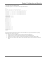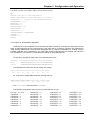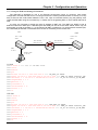
1
IPM-4SE
4-Port E1 IP Multiplexer
LEGAL
The information in this publication has been carefully checked and is believed to be entirely accurate at the
time of publication. CTC Union Technologies assumes no responsibility, however, for possible errors or
omissions, or for any consequences resulting from the use of the information contained herein. CTC Union
Technologies reserves the right to make changes in its products or product specifications with the intent to
improve function or design at any time and without notice and is not required to update this documentation
to reflect such changes.
CTC Union Technologies makes no warranty, representation, or guarantee regarding the suitability of its
products for any particular purpose, nor does CTC Union assume any liability arising out of the application
or use of any product and specifically disclaims any and all liability, including without limitation any
consequential or incidental damages.
CTC Union products are not designed, intended, or authorized for use in systems or applications intended to
support or sustain life, or for any other application in which the failure of the product could create a situation
where personal injury or death may occur. Should the Buyer purchase or use a CTC Union product for any
such unintended or unauthorized application, the Buyer shall indemnify and hold CTC Union Technologies
and its officers, employees, subsidiaries, affiliates, and distributors harmless against all claims, costs,
damages, expenses, and reasonable attorney fees arising out of, either directly or indirectly, any claim of
personal injury or death that may be associated with such unintended or unauthorized use, even if such claim
alleges that CTC Union Technologies was negligent regarding the design or manufacture of said product.
TRADEMARKS
Microsoft is a registered trademark of Microsoft Corp.
HyperTerminal™ is a registered trademark of Hilgraeve Inc.
FCC WARNING:
This equipment has been tested and found to comply with the limits for a Class A digital device, pursuant to
Part 15 of the FCC Rules. These limits are designed to provide reasonable protection against harmful
interference when the equipment is operated in a commercial environment. This equipment generates, uses,
and can radiate radio frequency energy and if not installed and used in accordance with the instruction
manual may cause harmful interference in which case the user will be required to correct the interference at
his own expense. NOTICE: (1) The changes or modifications not expressively approved by the party
responsible for compliance could void the user's authority to operate the equipment. (2) Shielded interface
cables and AC power cord, if any, must be used in order to comply with the emission limits.
CISPR PUB.22 Class A COMPLIANCE:
This device complies with EMC directive of the European Community and meets or exceeds the following
technical standard. EN 55022 - Limits and Methods of Measurement of Radio Interference Characteristics of
Information Technology Equipment. This device complies with CISPR Class A.
WARNING:
This is a Class A product. In a domestic environment this product may cause radio interference in which case
the user may be required to take adequate measures.
CE NOTICE
Marking by the symbol CE indicates compliance of this equipment to the EMC and LVD directives of the
European Community. Such marking is indicative that this equipment meets or exceeds the following
technical standards: EN 55022:1994/A1:1995/A2:1997 Class A and EN61000-3-2:1995, EN61000-3-3:1995
and EN50082-1:1997
CTC Union Technologies Co., Ltd.
Far Eastern Vienna Technology Center (Neihu Technology Park)
8F, No. 60, Zhouzi St.
Neihu, Taipei, 114
Taiwan
Phone: +886-2-2659-1021
FAX: +886-2-2799-1355
IPM-4SE
4-Port E1 IP Multiplexer (TDM over IP)
User Manual
Version 0.9c March 16, 2011
Version 1.0 September 28, 2011 (Updated and released as 1.0)
This manual supports the following models:
IPM-4SE AC
IPM-4SE DC
This document is the current official release manual. Please check CTC Union's website for any updated
manual or contact us by E-mail at [email protected]. Please address any comments for improving this manual
or to point out omissions or errors to [email protected]. For technical support for this product or other
CTC Union products, contact our support staff at [email protected]. Thank you.
©2010-2011 CTC Union Technologies Co.,Ltd.
All Rights Reserved
The contents of this document are subject to change without any prior notice.
Table of Contents
CHAPTER 1. INTRODUCTION ...................................................................................................................7 1.1 WELCOME .................................................................................................................................................7 1.2 PRODUCT DESCRIPTION ............................................................................................................................7 1.3 FEATURES..................................................................................................................................................7 1.4 PHYSICAL APPEARANCE ...........................................................................................................................8 1.5 IPM-4SE APPLICATION .............................................................................................................................8 1.6 IPM-4SE SPECIFICATIONS ........................................................................................................................8 CHAPTER 2. INSTALLATION...................................................................................................................10 2.1 INTRODUCTION........................................................................................................................................10 2.2 UNPACKING .............................................................................................................................................10 2.3 SITE PREPARATION .................................................................................................................................10 2.4 MECHANICAL ASSEMBLY ......................................................................................................................10 2.5 ELECTRICAL INSTALLATION ..................................................................................................................11 2.6 RACK INSTALLATION .............................................................................................................................11 2.7 BASIC CONFIGURATION AND DIAGNOSIS ...............................................................................................12 2.7.1 Utilize tools for diagnosis ................................................................................................................12 2.7.2 Basic Troubleshooting .....................................................................................................................12 2.8 LED INDICATORS ....................................................................................................................................12 CHAPTER 3. CONFIGURATION AND OPERATION............................................................................13 3.1 DESCRIPTION ...........................................................................................................................................13 3.2 FRONT PANEL INTRODUCTION ................................................................................................................13 3.2.1 System Indicators .............................................................................................................................13 3.2.2 Reset Button .....................................................................................................................................13 3.2.3 LAN & MNT Ethernet Connectors and Indicators...........................................................................13 3.2.4 Alarm LED Display..........................................................................................................................13 3.2.5 RS232 Connector .............................................................................................................................13 3.2.6 MNT Port (10/100M Ethernet Port for Telnet, or SNMP-based Management)...............................13 3.3 REAR PANEL INTRODUCTION ..................................................................................................................14 3.3.1 WAN Interface: ................................................................................................................................14 3.3.2 AC Power Socket and Switch (On/Off switch for AC): ....................................................................14 3.3.3 DC Power Socket and Switch (On/Off switch for DC): ...................................................................14 3.4 LOOPBACK MODE ...................................................................................................................................14 3.5 IP CONFIGURATION .................................................................................................................................14 3.6 INTERFACE CONFIGURATION ..................................................................................................................14 3.7 FAULT REPORT ........................................................................................................................................15 3.8 SAVE CONFIGURATION ...........................................................................................................................15 3.9 COMMAND LINE INTERFACE SETUP ........................................................................................................15 3.9.1 Using HyperTerminal™ as Local Console Terminal ......................................................................15 3.9.2 Telnet in for Remote Console Terminal ...........................................................................................15 3.10 FACTORY DEFAULT SCRIPTS ................................................................................................................18 3.10.1 Determine Device MAC Address ...................................................................................................18 3.10.2 CO Unit Factory Default Script.....................................................................................................18 3.10.3 CPE Unit Factory Default Script ...................................................................................................19 3.11 APPLICATION EXAMPLES ......................................................................................................................20 3.11.1 Point-to-Point with single E1 (port1) and LAN port active. ..........................................................20 3.11.2 Point-to-Point with Single E1 (port 1), Fractional /w CRC4 (nx64, n=8) active. .........................20 3.11.3 Notes on Fractional E1 Operation.................................................................................................21 3.11.4 Using the IPM in a Routing Environment......................................................................................22 APPENDIX .....................................................................................................................................................23 ABBREVIATIONS ...........................................................................................................................................23 i
Table of Contents
ii
Chapter 1 Introduction
Chapter 1. Introduction
1.1 Welcome
In telecommunications, TDM over IP (TDMoIP) is the emulation of time-division multiplexing (TDM) over
a packet switched network (PSN). In the case of the IPM-4SE, TDM refers to E1 signals, while the PSN is
based on Ethernet.
TDM over IP is a type of pseudo wire (PW). However, unlike other traffic types that can be carried over
pseudo wires (e.g. ATM, Frame Relay, and Ethernet), TDM is a real-time bit stream, leading to TDM over
IP having unique characteristics. In addition, conventional TDM networks have numerous special features, in
particular those required in order to carry voice-grade telephony channels. These features imply signaling
systems that support a wide range of telephony features, a rich standardization literature, and well-developed
Operations and Management (OAM) mechanisms.
One critical issue in implementing TDM PWs is clock recovery. In native TDM networks the physical layer
carries highly accurate timing information along with the TDM data which is easily recovered using phaselocked loop (PLL) techniques. However, when emulating TDM over PSNs this synchronization is absent.
TDM timing standards can be exacting, and conformance with these may require innovative mechanisms to
adaptively reproduce the TDM timing.
Another issue that must be addressed is TDM over IP packet loss concealment (PLC). Since TDM data is
delivered at a constant rate over a dedicated channel, the native Ethernet network may have bit errors. All
PSNs suffer to some degree from packet loss, and this must be compensated when delivering TDM over a
PSN.
1.2 Product Description
The IPM-4SE series is a "Multi-service (TDM and Ethernet) Over LAN/MAN" bridge, which transports one,
two, three, or four ports of ITU-T G.703 E1 and one LAN into Ethernet packets. Its target application shown
in Figure 1.2 is the transparent E1 port interconnection via the Ethernet network (using Ethernet packets).
Based upon RFC3916, the IPM-4SE series employs the latest Circuit Emulation System over packet
technology.
The E1 over IP of IPM-4SE is compliant with IETF “CES over IP” standard. Versatile LEDs are provided
for alarms and status indication.
1.3 Features
•
•
•
•
•
•
•
•
•
•
•
Supports E1 (only) over 100M Ethernet to LAN/MAN.
Provide one LAN for Ethernet access.
User side provides standard PDH (E1 only) interfaces using balanced signals for twisted pair.
Full-duplex 100M Ethernet Interface.
Provides auto-negotiation which can auto configure 10/100M depending on the speed of LAN/MAN port.
Supports "E1" Timing, i.e. LAN/MAN bandwidth requires at leased 5MHz or 10MHz.
Provides "ACT" and "ALM" LED indicators for each PDH interface.
Provides "Link status, Activity" LED indicators for 100M Ethernet interface.
Stand–alone desktop unit, optional 19" rack mountable.
Supports AC 100 ~ 240V input and optional DC -36 ~ -75V input for redundancy.
Important: T1(DS1) is currently not supported in this model.
7
Chapter 1 Introduction
1.4 Physical Appearance
Figure 1.1 IPM-4SE 4-Port E1 Physical Appearance
Important: T1(DS1) is currently not supported in this model
1.5 IPM-4SE Application
The IPM-4SE is mainly applied for the solution of wire-line application connecting PSTN via E1 and Router
via 100BaseTx and for integrating various equipments based on traditional TDM and popular IP services.
Figure 1.2 IPM-4SE 4-Port E1/T1 Application
1.6 IPM-4SE Specifications
100M Ethernet Interface
• Compliant with 802.3/802.3u standards
• 10/100-BaseT with RJ-45 connector
• Full-duplex
• Supports Auto-Negotiation per IEEE802.3u
• LED indicators for Ethernet: Link status and Activity
PDH Interfaces x 4
E1 Interface
Data Rate: 2.048 Mbit/s ± 50 ppm
Line Code: HDB3
Impedance: 120 ohms ± 5% resistive, balanced.
LED indications for E1: ACT, ALM
Connector Type: RJ-45 per USOC RJ-48C (Rx pair 1&2; Tx pair 4&5)
8
Chapter 1 Introduction
Power Supply
AC: 100~240V ± 10%, 47 ~ 63Hz
(Optional) DC: -18 ~ -75 V
Power Consumption: less than 10W
Operating Environment
Ambient temperature: 0 ~ 40°C for indoor application
(Optional): 0 ~ 55°C
Storage temperature: 0 ~ 85°C
Relative humidity: 5 ~ 95% non condensing
Physical Dimension
Height: 44.5 mm (1U)
Width: 370 mm
Depth: 215 mm
Weight: 2 Kg (net)
9
Chapter 2 Installation
Chapter 2. Installation
2.1 Introduction
The Installation chapter will cover the physical installation of the IPM-4SE, 4-Port E1 IP Multiplexer, the
electrical connections, interface connections and cabling requirements. A brief overview of the functional
components such as main unit and management options will also be outlined in this chapter.
Required Tools
You will need these tools to install the IPM-4SE:
Number 2 Phillips screwdriver for the 3mm and the 12-24 rack installation screws.
Wrist strap or other personal grounding device to prevent ESD occurrences.
Antistatic mat or antistatic foam to set the equipment on.
2.2 Unpacking
If there is a possibility for future relocation of the IPM-4SE unit, please keep the packing cartons and
protection packaging materials. Carefully unpack and inspect the unit and accessories for potentially
damaged or missing parts. Contact our nearest sales representative or our company directly if you detect any
damaged or missing parts. Improper handling during shipment may cause early failure. Notify the shipper or
forwarder immediately if the outer package shows signs of dropping or rough handling.
2.3 Site Preparation
Install the IPM-4SE within reach of an easily accessible grounded AC outlet or three wire (-48VDC, Power
return, Earth Ground) central office power. The AC outlet should be capable of furnishing 90 to 250 VAC.
Refer to 2.4 Electrical Installation. Allow at least 10cm (4 inch) clearance at the front of the IPM-4SE for the
E1 and LAN copper cables.
2.4 Mechanical Assembly
The IPM-4SE is designed for desktop, shelf or rack mount installation and will require 1U space in a
standard EIA 19" rack. The IPM-4SE chassis is delivered completely assembled upon delivery. The rack
mount adapters may be placed along the front of the chassis as shown below.
Figure 2.1 Standard 19" Rack-Mount Installation of IPM-4SE Unit requires 1RU space
10
Chapter 2 Installation
2.5 Electrical Installation
With an AC power model, AC power is supplied to the IPM-4SE through a standard IEC C14 3-prong receptacle,
located on the rear of the unit. Any national power cord with IEC C13 line plug may be used to connect AC power to
the power module. With a DC model, DC -48V is connected to the terminal block located on the rear of the module,
observing the proper polarity. The IPM-4SE should always be grounded through the protective earth lead of the power
cable in AC installations, or via the frame ground connection for DC installations.
Left: Live line
Right: Neutral line
Middle: Ground
-V
DC IN
FG +V
IEC C13 line plug
Left: -V (-48V)
Right: +V (0V)
Middle: Frame Ground
36~75VDC
Figure 2.2 IEC (AC) & terminal block (DC) power connector pin assignment
2.6 Rack Installation
There are 3 common parts for each IPM-4SE package, including 1 set of TDM over IP multiplexer, 1 AC
power cord. If the IPM-4SE is intended for mounting into a rack, a pair of L-type Steel brackets with 16
screws should be requested with the user's order. The user manual, an electronic PDF format file, will be
included on a CD-ROM along with any accessory files such as SNMP MIB files and example script files.
The following Figure 2.3 shows desktop or shelf operation and Figure 2.4 shows rack mounting of the IPM4SE.
Figure 2.3 Stand-alone shelf or tabletop use
Rack Brackets
h
Figure 2.4 Rack mounted use
11
Chapter 2 Installation
2.7 Basic Configuration and Diagnosis
The IPM-4SE units are shipped in pre-configured pairs. One is labeled CO (central office) and the other
labeled CPE (customer premises equipment). Simply place the CO unit towards the E1 clock source (SDH
multiplexer, BSC, carrier, etc.) and place the CPE unit connecting to the E1 recovery equipment (DSU/CSU,
BTS, customer, etc.). After installing the device and powering on, if E1 transmission does not immediately
work, follow the diagnostics and basic troubleshooting.
2.7.1 Utilize tools for diagnosis
•
•
•
•
Maintain and troubleshoot the status from LED indications, shown below.
Connect basic VT100 terminal to console port using 115.2K, 8bit, no parity, 1 stop bit no flow control
Telnet NE using port 8888 to show the alarm or status if association still works.
Associate NE via IPM-4SE GUI (tbd) to diagnose if configuration is correct and what status occurs.
2.7.2 Basic Troubleshooting
• If a ping of the remote NE via LAN/MAN does not respond, then please check the LAN connections and
make sure Switch/LAN/MAN are working.
• If TDM or LAN provides unstable quality of service, please check the link performance or access port
(E1/LAN) and reset the NE.
2.8 LED Indicators
LED Name
PWR
ALM
Light Status
Green
Red
Descriptions
Power is on
Raised from any PDH link alarms
Table 2.1 Chassis LED Indications of IPM-4SE
LED Name
ACT
ALM
Light Status
Green
Yellow
Descriptions
E1 traffic is active (Ports 1~4)
Raised from E1 link alarms (Ports 1~4)
Table 2.2 E1 LED Indications of IPM-4SE
LED Name
Ethernet LINK
Ethernet ACT
Light Status
Green
Blinking Yellow
Descriptions
Ethernet link is up
TX or RX Ethernet traffic is active
Table 2.3 MNT, LAN and WAN (RJ-45) LED Indications of IPM-4SE
12
Chapter 3 Configuration and Operation
Chapter 3. Configuration and Operation
3.1 Description
IPM-4SE consists of the front panel and the rear panel. The views and description of front and rear panels
are shown in Figure 3.1 and 3.2.
The IPM-4SE units are shipped in pre-configured pairs. One is labeled CO (central office) and the other
labeled CPE (customer premises equipment). Be sure to carefully check the model's sticker. Simply place
the CO unit towards the E1 clock source (SDH multiplexer, BSC, carrier, etc.) and place the CPE unit
connecting to the E1 recovery equipment (DSU/CSU, BTS, customer, etc.).
3.2 Front Panel Introduction
There are 6 items that need to be mentioned on the front panel of IPM-4SE.
3.2.1 System Indicators
PWR (Power Exist LED) Make sure power is available and switch is turned on
ALM (for any of E1 Links or WAN port Status)
3.2.2 Reset Button
Provides the facility of rebooting the system without powering off.
3.2.3 LAN & MNT Ethernet Connectors and Indicators
The Lan and MNT Ethernet interfaces use an RJ-45 connector with LED indicators
There are green and yellow LED indicators:
• Green Link (Link Up/Down Status)
• Yellow Act (TX/RX Active Status)
3.2.4 Alarm LED Display
E1/T1 Interface
• Green ACT (E1 Port Traffic)
• Yellow ALM (E1 Port Link Status)
The "RED" chassis LED indicates one of the following alarms occurred:
E1/T1 LOS, AIS, L-bit or no received traffic from WAN port
3.2.5 RS232 Connector
An RS232 interface with baud-rate 115200bps via DB9 (female)-to-DB9 (male) cable is provided for
diagnostics. The user commands (CLI command) are listed in Table 3.1.
3.2.6 MNT Port (10/100M Ethernet Port for Telnet, or SNMP-based Management)
Provides a user management interface - Telnet or SNMP, via MNT port for managing the local & remote
NEs.
Figure 3.1 IPM-4SE 4-Port E1 Front Panel View
13
Chapter 3 Configuration and Operation
3.3 Rear Panel Introduction
There are three parts to the rear panel of the IPM-4SE, shown in Figure 3.2.
Figure 3.2 IPM-4SE 4-Port E1/T1 Rear Panel View
3.3.1 WAN Interface:
The Ethernet WAN interface is an RJ-45 connector with LED
There are green and yellow LED indicators:
• Green Link (Link Up/Down Status)
• Yellow Act (TX/RX Active Status)
3.3.2 AC Power Socket and Switch (On/Off switch for AC):
The power socket provides the power with an input range of AC 110 ~ 240V via standard IEC connector.
3.3.3 DC Power Socket and Switch (On/Off switch for DC):
The power terminal strip provides the power with an input range of DC -75 ~ -36V
3.4 Loopback Mode
The IPM-4SE provides two types of loopback: "E1 Remote Loopback" and "E1 Local Loopback". (Please
refer to Figure 3.4).
Remote Loopback
Local Loopback
TDM
IPM-4SE
IPM-4SE
TDM
LAN/MAN
Figure 3.4 IPM-4SE E1 Loopback Mode
3.5 IP Configuration
The IP address, subnet mask address, and Gateway address of the management port (MNT) should be setup
thru RS232 console using CLI commands.
3.6 Interface Configuration
For the LAN configuration, the setting of traffic bandwidth is provided to ensure the quality of service in
TDM circuits with 16 throughput options of 50K, 100K, 150K, 200K, 250K, 300K, 350K, 400K, 800K,
1.6M, 3.2M, 6.4M, 12.8M, 25.6M, 51.2M and 100M, depending on the user's requirement. In addition,
setting 100M option will utilize all the available bandwidth to LAN with no QoS for E1 traffic.
For the E1 configuration, the LEDs will be lit after enabling the E1 channel and user can select the remote
output E1 channel for flexible cross connection purposes. A Jitter Buffer is also used to compensate for the
latency of real network traffic between two devices. The Jitter buffer includes 8 options which are 11, 23, 40,
75, 99, 145, 192, and 239 ms.
14
Chapter 3 Configuration and Operation
3.7 Fault Report
The alarms/status of NE node can be reported thru RS232 or Telnet (CLI command). The resource of alarms
is only from TDM interface (E1) and the acronym alarm names are shown as follows.
E1LOS: (E1 Loss of Signal) No E1 line connected to the specific E1 port.
E1AIS: (E1 Alarm Indication Signal) AIS (all 1’s) signal input from the specific E1 port.
PWLBIT: (Pseudo Wire L bit) Remote E1 port failure condition (LOS or AIS).
PWRBIT: (Pseudo Wire R bit) Packet loss occurred at remote E1 port.
PWSEQNUMERR: (Pseudo Wire Sequence Number Error) Packet loss occurred for specific E1 local
port.
JBUFEMP: (Jitter Buffer Empty) Buffer empty occurred at specific E1 port. (typically from link
down or mis-configuration.) If link is good, increase the jitter buffer at the expense of latency.
JBUFOV: (Jitter Buffer Overflow) Buffer overflow occurred at specific E1 port. There is probably a
problem with bi-direction throughput of the Ethernet WAN link.
3.8 Save Configuration
After changing the configurations from CLI or Telnet, the "SAVE" action should be done to store the
configuration into non-volatile storage. This can avoid loosing settings if the device is rebooted or powered
off/on.
3.9 Command Line Interface Setup
3.9.1 Using HyperTerminal™ as Local Console Terminal
When logging into the HyperTerm, set up the terminal port as follows:
• Bit rate: 115200bps
• Data bit: 8
• Parity: none
• Stop bit: 1
• Flow control: none
• Login password: admin (factory default)
3.9.2 Telnet in for Remote Console Terminal
If using the "Telnet" command in an Operation System, such as Windows or Linux, the default port of the
IPM-4SE is 8888 instead of the standard port 23 for security issue. The default IP address of the management
port is 192.168.1.1 and net mask is 255.255.255.0. The IP address, therefore, of the Telnet Client needs to be
set in the IP range 192.168.1.2 to 192.168.1.254 and the same net mask. An example of a command line in
Windows would be the following:
C:\WINDOWS\system32> telnet 192.168.1.1 8888
The factory default login password in both serial console CLI and Telnet modes is "admin". The CLI user
commands are listed in the following table for detail and implemented on CLI and TELNET modes:
3.9.3 Setting CLI (Telnet) login password
Important: DO NOT FORGET the password once changed or you must return the unit to factory. There is no
back-door password or any recovery procedure.
CLI> setpass c
===== Set Password for CLI Login =====
Enter Old Password: admin ==> OK!
Enter New Password: *** ==> OK!
Re-Enter New Password: *** ==> OK!
CLI>
15
Chapter 3 Configuration and Operation
CLI Command Descriptions
CLI Command System Commands logout cdisp csave cload reboot passwd setpass mode ipset ip_addr net_mask gateway_ip ipget trapset mode trap_ip_addr trapget ntpset mode server_ip_addr ntpget upgrade server_ip file_name backup tftp_server_ip file_name restore tftp_server_ip file_name tgmode mode ceschclkset ch_num clksrc tgpriset 1st.source 2nd.source tge1loop e1_num tgget timeset hour min sec dateset year month day timeget lpkset ch_no mode enable
lpkget
ping ip_addr
Descriptions Logout from the CLI System Display IPM‐4SE current configurations. Save current configurations: IPM‐4SE & relative settings. Load configuration setting from FLASH. Reboot command to use after saving configuration Enter password to change user‐mode. (i.e. View/Setup/Admin mode) PS: If inputted password is not for "setup" or "admin", it will enter the "view" mode. Modify password for user‐mode. mode: ‘s’ for setup mode, ‘a’ for admin mode. Set IPM‐4SE IP address, net mask and gateway IP address. ip_addr: IP Address, net_mask: net mask, gateway_ip: gateway IP. EX: ipset 192.168.1.28 255.255.255.0 192.168.1.254 Get IPM‐4SE current IP address, net mask, and gateway IP address. Set SNMP Trap Mode & Host IP mode: 0 for disabling SNMP trap, 1 for enabling SNMP trap EX: trapset 1 192.168.6.3 (enables trap sending to 192.168.6.3 manager) Get SNMP Trap Mode & Host IP Set NTP Enable Mode & NTP Server IP mode: 0 for disable NTP function, 1 for enable NTP function Get NTP Enable Mode & NTP Server IP Upgrade Software image file from TFTP server server_ip: TFTP server IP address file_name: SW image file name EX: upgrade 192.168.2.199 ipm130.bin Backup the system configuration to TFTP server tftp_server_ip: the TFTP server IP address file_name: the backup file name EX: backup 192.168.2.199 ipm4se_co_backup_1 Restore the system configuration from TFTP server tftp_server_ip: the TFTP server IP address file_name: the backup file name EX: restore 192.168.2.199 ipm4se_co_backup_1 Set TG Mode mode: 0 for Global mode, 1 for E1‐Indep mode Set Channel Timing Gen Clock Source ch_no: E1 channel number. clksrc: 0:Adaptive (remote), 1:Internal, 2:E1 Recovery, 3:Bits. Set TG Clock Priority Source source: 0:Ext.BITS, 1:Global.TG, 2:HoldOver, 3:FreeRun Set TG Secondary Clock Source Input e1_num: 1 ~4 for E1#1 ~ E1#4 Get TG Mode and Status Set current time with ‘hour’, ‘minute’ and ‘second’. Set current date with ‘year’, ‘mouth’ and ‘day’ Get current time and date Enable/Disable E1 channel loopback mode.
ch_no: E1 channel number.
mode: 0:Disable-All, 1:E1-Remote (FE), 2:E1-Local (NE)
enable: 0:disable, 1:enable.
EX: lpkset 1 1 1
Get current loopback mode of E1 channel.
Use ICMP to check connection
EX: ping 192.168.1.28
16
Chapter 3 Configuration and Operation
CLI Command Provisioning Commands Descriptions Initialize GCI Middle Ware & CESoPSN chip Initialize relative Tasks, Messages and Semaphores. CAUTION: This will clear all the configuration. cesopget Get current CESoPSN Setting. Set CESoPSN IP address, net mask and gateway IP address. srcnet ip_addr net_mask gateway_ip ip_addr: IP Address, net_mask: net mask, gateway_ip: gateway IP. EX: srcnet 192.169.1.28 255.255.255.0 192.169.1.254 Set CESoPSN LAN Traffic Enable and Bandwidth. enable: 0:disable, 1: enable. lanset enable bandwidth bandwidth: 0~15 (0: 50K, 1:100K, 2:150K, 3:200K, 4:250K, 5:300K, 6:350K, 7:400K,
8:800K, 9:1.6M, 10:3.125M, 11:6.25M, 12:12.5M, 13:25M, 14:50M, 15:100M) EX: lanset 1 15 (use the rest of BW minus TDM traffic) vlanset enable Set Vlan Mode enable/disable Set CESoPSN Channel Enable, Destination IP and MAC. ch_no: E1 channel number (1~4) enable: 0:disable, 1: enable. dest_ip: destination node IP address. ceschset ch_no enable dest_ip dest_mac dest_mac: destination node MAC address Situation 1: Set dest_ip, then get dest_mac from far end EX: ceschset 1 1 192.168.1.28 Situation 2: Set dest_ip and dest_mac manually EX: ceschset 1 1 192.168.1.28 AA:BB:CC:DD:EE:FF Set CESoPSN Channel TrPWID and PrPWID. ch_no: E1 channel number (1~4) cespwidset ch_no TrPWID PrPWID TrPWID: Transmit PseudoWire ID. PrPWID: Provision PseudoWire ID. EX: cespwidset 1 1 1 Set CESoPSN Channel Jitter Buffer Depth. Initial Jitter DS is 3. ch_no: E1 channel number (1~4) jitterbd ch_no depth depth: jitter buffer depth 0~7 (0:11ms, 1:23ms, 2:40ms, 3:75ms, 4:99ms, 5:145ms, 6:192ms, 7:239ms) EX: jitterbd 1 2 (Suggested default is to set 40 ms for general uplink latency) Set CESoPSN Channel Packet Size pktsize ch_no pkt_size Pkt_size: 0: 1514 Byte, 1: 782 Byte, 2: 178 Byte. 3: 306 Byte. cesfe1mode ch_no enable cesfe1crc ch_no enable cesfe1tsmap ch_no TsMap Set CESoPSN EBER Enable and Threshold. ch_no: E1 channel number (1~4) eberset ch_no enable threshold enable: 0:disable, 1: enable. threshold: 0 ~ 3 (0:10^‐3, 1:10^‐4, 2:10^5, 3:10^‐6) ceschtgpriset ch_no 1st.source Set CESoPSN Channel clock priority source in TG mode 2nd.source Source: 1:E1.TG, 2:HoldOver, 3:FreeRun. Set CESoPSN Channel vlan tag ceschvlanvlpid ch_no vlp id vlp:0 ~ 7, id: 0 ~ 0xFFF eberget Get CESoPSN EBER Enable and Threshold. Alarm Command almall Display all alarm status (CESoPSN) gci Table 3.1 CLI Command Descriptions
17
Chapter 3 Configuration and Operation
3.10 Factory Default Scripts
When delivered from the factory, the units are paired as CO and CPE for immediate point-to-point use, with
all 4 E1s enabled, unframed, and LAN enabled. Because these units operate at Ethernet Layer 2, we address
the remotely connected pseudowire by MAC address.
If the device sticker has been lost, or if the MAC address has been inadvertently changed, the MAC for both
the MNT port and WAN port can be viewed through the CLI. Below is an example.
3.10.1 Determine Device MAC Address
CLI>m 4321
====== CLI: MW Test Functions ======
m 4321 OUI(xx:xx:xx)
===== Config: HW/SW MAC = 1 (HW_MAC).
===== Config: OUI-Addr = 00:02:AB.
===== Config: eth0 Addr = 00:02:AB:16:CD:13. <== this is NMS MAC Source
===== Config: eth1 Addr = 00:02:AB:16:CD:12. <== this is WAN MAC Source
3.10.2 CO Unit Factory Default Script
CO default, replace xx:xx:xx with CPE unit’s unique MAC Address
gci
srcnet 172.16.1.1 255.255.255.0
ipset 192.168.1.11 255.255.255.0 172.16.1.2
ceschset 1 1 172.16.1.2 00:02:AB:xx:xx:xx
ceschset 2 1 172.16.1.2 00:02:AB:xx:xx:xx
ceschset 3 1 172.16.1.2 00:02:AB:xx:xx:xx
ceschset 4 1 172.16.1.2 00:02:AB:xx:xx:xx
cespwidset 1 1 1
cespwidset 2 2 2
cespwidset 3 3 3
cespwidset 4 4 4
pktsize 1 0
pktsize 2 0
pktsize 3 0
pktsize 4 0
jitterbd 1 1
jitterbd 2 1
jitterbd 3 1
jitterbd 4 1
ceschclkset 1 2
ceschclkset 2 2
ceschclkset 3 2
ceschclkset 4 2
lanset 1 7
csave
18
Chapter 3 Configuration and Operation
3.10.3 CPE Unit Factory Default Script
CPE default, replace xx:xx:xx with CO unit's unique MAC address
gci
srcnet 172.16.1.2 255.255.255.0
ipset 192.168.2.11 255.255.255.0 172.16.1.1
ceschset 1 1 172.16.1.1 00:02:AB:xx:xx:xx
ceschset 2 1 172.16.1.1 00:02:AB:xx:xx:xx
ceschset 3 1 172.16.1.1 00:02:AB:xx:xx:xx
ceschset 4 1 172.16.1.1 00:02:AB:xx:xx:xx
cespwidset 1 1 1
cespwidset 2 2 2
cespwidset 3 3 3
cespwidset 4 4 4
pktsize 1 0
pktsize 2 0
pktsize 3 0
pktsize 4 0
jitterbd 1 1
jitterbd 2 1
jitterbd 3 1
jitterbd 4 1
ceschclkset 1 0
ceschclkset 2 0
ceschclkset 3 0
ceschclkset 4 0
lanset 1 7
csave
The factory default scripts allow the units to connect with 4xE1 over any LAN environment. To quickly
modify these two scripts for your LAN:
1. Change the ‘srcnet’ IP address to the new IP you want for the WAN port.
2. Change the ‘ipset’ to the IP, Subnet and GW for the MNT (management) port.
3. Change the ‘ceschset’ IP address to be the WAN destination for the PW (the opposite IPM)
4. Make sure the ‘ceschset’ MAC address is the actual MAC address of the destination unit (opposite
IPM).
19
Chapter 3 Configuration and Operation
3.11 Application Examples
3.11.1 Point-to-Point with single E1 (port1) and LAN port active.
CO Side: (use the correct MAC address for the remote CPE unit)
gci
srcnet 172.16.1.1 255.255.255.0
ipset 192.168.1.11 255.255.255.0 172.16.1.2
ceschset 1 1 172.16.1.2 00:02:AB:xx:xx:xx
cespwidset 1 1 1
pktsize 1 0
jitterbd 1 1
ceschclkset 1 2
lanset 1 7
csave
CPE Side: (use the correct MAC address for the local CO unit)
gci
srcnet 172.16.1.2 255.255.255.0
ipset 192.168.2.11 255.255.255.0 172.16.1.1
ceschset 1 1 172.16.1.1 00:02:AB:xx:xx:xx
cespwidset 1 1 1
pktsize 1 0
jitterbd 1 1
ceschclkset 1 0
lanset 1 7
csave
3.11.2 Point-to-Point with Single E1 (port 1), Fractional /w CRC4 (nx64, n=8) active.
CO Side: (use the correct MAC address for the remote CPE unit)
gci
srcnet 172.16.1.1 255.255.255.0
ipset 192.168.1.11 255.255.255.0 172.16.1.2
ceschset 1 1 172.16.1.2 00:02:AB:xx:xx:xx
cespwidset 1 1 1
pktsize 1 0
jitterbd 1 1
ceschclkset 1 2
cesfe1mode 1 1
cesfe1crc 1 1
cesfe1tsmap 1 x000001FE
lanset 0
csave
20
Chapter 3 Configuration and Operation
CPE Side: (use the correct MAC address for the local CO unit)
gci
srcnet 172.16.1.2 255.255.255.0
ipset 192.168.2.11 255.255.255.0 172.16.1.1
ceschset 1 1 172.16.1.1 00:02:AB:xx:xx:xx
cespwidset 1 1 1
pktsize 1 0
jitterbd 1 1
ceschclkset 1 0
cesfe1mode 1 1
cesfe1crc 1 1
cesfe1tsmap 1 x000001FE
lanset 0
lanset 1 7
csave
3.11.3 Notes on Fractional E1 Operation
If IPM carries E1 as 'unframed', then it becomes transparent (SAToP). As long as the equipment on both
sides of IPM equipment have the same framing, then there will be no alarms. However, the advantage of
using framing (CESoPSN) is that the data bandwidth can be reduced considerably by sending only the
payload, especially over a satellite link. You must make sure the right timeslots are enabled and match the
crc4 if enabled or not (cesfe1crc). Duplicate these settings on both IPM4SE units.
For the hex to timeslot bit mask, each TS is represented by a bit:
TS bits : 11111111111111111111111111111111
TS #
33222222222211111111110000000000
31~0
10987654321098765432109876543210
If we breakup into octets, then we can assign hex values:
1111|1111|1111|1111|1111|1111|1111|1111
F | F | F | F | F | F | F | F
So, if we want to enable fifteen timeslots, starting with TS1:
0000|0000|0000|0000|1111|1111|1111|1110
0 | 0 | 0 | 0 | F | F | F | E
The cesfe1tsmap value would be x0000FFFE
If the timeslot range always starts at TS1, this table will work for you:
hex map no. of TS
x00000002 = 1
x00000006 = 2
x0000000E = 3
x0000001E = 4
x0000002E = 5
x0000006E = 6
x000000FE = 7
x000001FE = 8
x000002FE = 9
x000006FE = 10
x00000FFE = 11
x00001FFE = 12
x00002FFE = 13
x00006FFE = 14
x0000FFFE = 15
x0001FFFE = 16
x0002FFFE = 17
x0006FFFE = 18
x000FFFFE = 19
x001FFFFE = 20
x002FFFFE = 21
x006FFFFE = 22
x00FFFFFE = 23
21
x01FFFFFE = 24
x02FFFFFE = 25
x06FFFFFE = 26
x0FFFFFFE = 27
x1FFFFFFE = 28
x2FFFFFFE = 29
x6FFFFFFE = 30
xFFFFFFFE = 31
Chapter 3 Configuration and Operation
3.11.4 Using the IPM in a Routing Environment
The IPM-4SE is designed for use in an Ethernet environment (Layer 2). However, with proper
configuration, the IPM-4SE will work in a routing environment. Knowing the Router MAC is the key. It is very
easy to discover the router’s MAC address. From a PC, open a command window, ping the gateway, then
check the ARP table using the command arp –a. Make note of the gateway MAC on each subnet that has an
IPM.
It is also very important to assign the right IP address to MNT port. The MNT port MUST be set to
different subnet from WAN port. If the MNT port and WAN port are set to the same subnet, IPM-4 may not
know where to route its packets, i.e., to the Router via MNT or WAN port. If it routes packets via MNT port,
the CESoTDM packets will not be delivered to Router for forwarding to the remote side.
CO
CPE
10.10.1.1/24
10.10.2.1/24
WAN
WAN
10.10.1.254/24
10.10.2.254/24
00:48:54:5c:ca:fc
00:40:f4:47:ba:24
MNT
MNT
10.10.3.1
10.10.4.1
RS-232 115.2k
10.10.1.20
CO Side
CLI>m 4320 0 <== Set to SW MAC mode
CLI>csave
CLI>reboot
CLI>gci
CLI>srcnet 10.10.1.1 255.255.255.0 <== CO_Wan_IP Mask
CLI>ipset 10.10.3.1 255.255.255.0 10.10.1.254 <== MNT_IP Mask Default_GW
CLI>ceschset 1 1 10.10.2.1 00:48:54:5c:ca:fc <== ch_no en remote_ip GW_MAC
CLI>cespwidset 1 1 1
CLI>pktsize 1 1
CLI>jitterbd 1 1
CLI>ceschclkset 1 0
CLI>lanset 1 7
CLI>cs
CPE Side
CLI>m 4320 0
CLI>csave
CLI>reboot
CLI>gci
CLI>srcnet 10.10.2.1 255.255.255.0 <== CPE_Wan_IP Mask
CLI>ipset 10.10.4.1 255.255.255.0 10.10.2.254 <== MNT_IP Mask Default_GW
CLI>ceschset 1 1 10.10.1.1 00:40:f4:47:ba:24 <== ch_no en remote_ip GW_MAC
CLI>cespwidset 1 1 1
CLI>pktsize 1 1
CLI>jitterbd 1 1
CLI>ceschclkset 1 0
CLI>lanset 1 7
CLI>cs
22
Appendix
Appendix
Abbreviations
AC
AIS
ANSI
AP
BITS
BSC
BTS
CESoPSN
CLI
CO
CPE
DC
DLC
DSU/CSU
EIA
ESD
FE
FE1
IEC
ITU
LAN
LED
L-bit
LOS/LOF/PATH
MAC
MAN
MIB
NE
ODU
OOF
PBX
PDF
PDH
POTS
PSTN
PW
QoS
SAToP
SDH
SNMP
TDM
WAN
Alternating Current
Alarm Indication Signal
American National Standards Institute
Access Point
Building Integrated Timing Systems
Base Station Controller
Base Transceiver System
Circuit Emulation Service over Packet Switch Network
Command Line Interface
Central Office
Customer Premises Equipment
Direct Current
Digital Loop Carrier
Digital Service Unit/Channel Service Unit
Electronic Industries Alliance
Electro-Static Discharge
Fast Ethernet
Fractional E1
International Electrotechnical Commission
International Telecommunication Union
Local Area Network
Light Emitting Diode
Remote Defect Indication
Loss of Signal/Frame/Path Alarm
Media Access Control
Metro Area Network
Management Information Base
Network Element
Out Door Unit
Out of Frame
Private Branch eXchange
Portable Document File
Plesiochronous Digital Hierarchy
Plain Old Telephone System
Public Switched Telephone Network
Pseudowire
Quality of Service
Structure-Agnostic TDM over Packet
Synchronous Data Hierarchy
Simple Network Management Protocol
Time Division Multiplexing
Wide Area Network
23
Appendix
This page left blank intentionally.
24