1
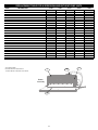
Installation, Operation and Maintenance
ULTRA-QUIET
H SERIES
Wallmount Heat Pumps
REV. 3/16/09
678629-H
TABLE OF CONTENTS
INSPECTION AND UNPACKING
A thorough inspection of the shipping container should be made
immediately upon receiving your unit. Look for any punctures or
openings. If it appears as if damage has occurred, it should be noted
on the freight bill before signing. The delivering carrier should be
contacted immediately to inspect damage, and no installation work
should begin until this inspection is completed.
Introduction .................................................................................2
Operating & Maintenance Instructions ........................................3
INSTALLATION
A. Codes ................................................................................4
B. Unit Site Location ..............................................................4
C. Unit Preparation.................................................................4
D. Ductwork ...........................................................................4
E. Filters.................................................................................4
F. Electrical Power.................................................................4
G. Breaker/Disconnect Assembly...........................................4
H. Electrical Hook-up .............................................................5
I. Low Voltage Wiring............................................................5
J. Unit Installation ..................................................................5
K. Condensate Drain..............................................................5
L. Electrical Heat Installation .................................................5
M. Defrost Control ..................................................................6
N. High Pressure Lock Out ....................................................6
Exploded Parts Drawings.........................................................7-8
Parts List ................................................................................9-11
Unit Dimensions ........................................................................13
Wiring Specifications.................................................................14
Wiring Diagrams ..................................................................15-17
NOTES TO INSTALLER
The words “SHALL” and “MUST” indicate a requirement which is
essential to satisfactory and safe product performance. The
words “SHOULD” and “MAY” indicate a recommendation or
advice which is not essential and not required but which may be
useful or helpful.
The instructions are for the use of qualified individuals specially trained
and experienced in the installation of this type equipment and related
system components.
Installation and service personnel are required by some locales to be
licensed. Persons not qualified SHALL NOT install this equipment nor
interpret these instructions.
NOTICE: This Installation, Operation and Maintenance Manual is
CONGRATULATIONS
provided to ensure the proper installation and most satisfactory
performance of your equipment. The instructions contained herein
SHALL NOT be deemed to extend, modify, alter or expand any of the
representations contained in the LIMITED WARRANTY.
You have made a major investment in a fine piece of equipment. Keep
your investment sound by reading these instructions before installing
this unit. This will ensure that the full potential of this equipment is
achieved. It will also be helpful in avoiding any needless service costs
or operational problems. Included in these instructions are safety
rules, installation, maintenance, and operation instructions.
SAFETY RULES
WARNING: FAILURE TO FOLLOW THESE RULES
AND INSTRUCTIONS COULD CAUSE A MALFUNCTION OR DESTRUCTION OF THE EQUIPMENT
WHICH COULD RESULT IN PROPERTY DAMAGE,
SERIOUS BODILY INJURY, OR DEATH.
!
Your equipment is covered by a LIMITED WARRANTY against
defects in material and workmanship. Make sure that your installing
dealer or contractor has returned the factory portions of the
LIMITED WARRANTY CARD with the information properly entered
to confirm the date of installation. Failure to return the warranty card
could result in the warranty period beginning at the date of
manufacture, instead of the date of installation.
1. Installation and repair MUST be done by a qualified person.
The equipment should be inspected before use and at least
once annually by a professional service person.
Only the highest quality components were used in the construction
of your unit. With proper maintenance, your system should provide
years of economical, trouble-free service.
2. AVOID ELECTRICAL SHOCK! Turn power OFF when
servicing. There may be more than one disconnect switch to
de-energize unit.
This is a vertical wallmount unit designed for many different
applications in both residential and commercial settings. It is selfcontained and arrives completely assembled, factory-charged and
wired. The unit is 100% run-tested at the factory to ensure proper
operation. Your unit is supplied with high-quality copper tubing and
enhanced aluminum-finned coils for high heat transfer efficiency
and long life. The unit cabinet is constructed of G-90 galvanized
steel. All exterior surfaces are finished with a baked-on polyester
coating. This will provide excellent corrosion protection in most
applications. However, if the unit is installed in an area with a
corrosive atmosphere, such as near an industrial plant or on the
seacoast, additional coating should be considered to extend the life
of the coils and cabinet.
3. Close cover(s) before returning breaker(s) to “ON” position.
4. Please observe good safety practices by wearing personal
protective equipment such as gloves and safety glasses to
avoid injury.
5. Installation MUST conform to local codes. In the absence of
local codes, refer to the National Electrical Code (NEC),
ANS/NFPA No. 70-1993 and recommendations made by the
National Board of Fire Underwriters.
In our continuing effort to improve our product, specifications may
change without notice. If there are any questions, please see the
contact information on the last page of this manual.
In all cases, the equipment MUST be installed in accordance with
the installation instructions described in this manual.
DANGER: BEFORE PERFORMING ANY WORK ON
THIS EQUIPMENT, POWER SUPPLY MUST BE
TURNED OFF AT THE HOUSEHOLD SERVICE BOX TO
AVOID THE POSSIBILITY OF SHOCK, INJURY, DEATH OR
DAMAGE TO EQUIPMENT.
!
!
2
WARNING: IMPROPER INSTALLATION MAY
DAMAGE EQUIPMENT, CAN CREATE A HAZARD, AND
WILL VOID THE WARRANTY.
OPERATING INSTRUCTIONS
Set the thermostat to either HEAT or COOL as desired. Set the
desired temperature on your thermostat dial and set the fan
switch to “ON” (for continuous air circulation) or to “AUTOMATIC”
(for air circulation only when the air conditioning system is
operating). If you desire to vary the thermostat temperature
setting during the day for energy conservation (for example, while
you are at work) do not vary the setting more than 5°F from your
normal temperature setting. Changing the temperature more than
5°F or turning the thermostat off for periods less than 12 hours
can actually cost you more in energy consumption than keeping
the temperature constant. You should also consider indoor plants
and pets when varying the temperature from the normal comfort
level.
IMPORTANT: Wait at least three (3) minutes after turning the
heat pump off before trying to restart. If an attempt is made to
start the compressor before the refrigerant pressures are
equalized, the compressor motor may trip on its overload. An
additional waiting period will be required before restarting.
MAINTENANCE
1. Always install and keep filters clean. Check filters every 10 days
to 2 weeks. Clean or replace if necessary. The factory-installed
filter is located behind the center front access panel.
!
TO CHANGE SYSTEM FILTER:
A. Turn the power to the unit off at the unit disconnect. The
disconnect is located on the front of the H Series unit behind
a small access door.
WARNING: SERIOUS INJURY MAY RESULT IF
WATER SPRAY IS DIRECTED TOWARD LIVE
ELECTRICAL CONNECTIONS OR POWER
SOURCES.
TO CLEAN FRESH AIR
INTAKE FILTER:
B. Remove the front center access door from the unit.
A. Follow steps A and B at left “TO
CHANGE SYSTEM FILTER”.
C. Remove and replace the filters with the type and size
indicated in the table below.
B. Gently pull out the filter from the
bottom.
D. Replace the access door and turn on the power to the unit.
INSULATION
2
1
CLOSED
DAMPER
DOOR
C. Wash the filter with water.
NOTE:
If your system has a filter grille installed in the return air
opening, the unit filter should have been discarded during
installation.
UNIT MODEL
QTY.
FILTER SIZE
TYPE
H24, H30, H36
H24, H30, H36
H48, H60
H48, H60
1
1
1
1
16 x 25 x 1 (standard)
16 x 25 x 2 (optional)
20 x 30 x 1 (standard)
20 x 30 x 2 (optional)
Disposable
Disposable
Disposable
Disposable
D. Reinstall the filter, by sliding it into
the retaining rail.
SCREW
FILTER
E. Replace the access door and turn
the power on to the unit.
2. Keep the outdoor coil clean. Wash it down with a garden hose if
necessary. BE SURE THE UNIT DISCONNECT IS IN THE
“OFF” POSITION AND THAT ALL ELECTRICAL POWER TO
THE UNIT IS TURNED OFF BEFORE CLEANING THE
SYSTEM.
Remove any loose grass, leaves, papers, etc., from the area
around the condenser coil. These could reduce the air
supply through the coil and reduce the amount of cooling
capacity.
The filter installed into the return air grille assembly should be
replaced with the same size and type provided with the grille.
3. Since the heat pump is located outdoors, it is exposed to all
weather elements. Treat it with a good automobile paste wax
twice a year (in the spring and fall).
If your system is equipped with a fresh air intake, the filter for the
fresh air assembly is accessed through the front center panel. The
filter is a permanent washable type.
Check with your contractor if you have any questions regarding
the maintenance or operation of your unit.
3
INSTALLATION
D. DUCTWORK
A. CODES
The installer SHALL comply with all local, state, and federal codes
and/or regulations pertaining to this type of equipment and its
installation. Such codes and/or regulations should take precedence
over any recommendations contained herein in lieu of local codes.
Installations SHALL be made in accordance with the National
Electrical Code, local codes, and recommendations made by the
National Board of Fire Underwriters.
1. Properly-sized duct systems are critical for satisfactory
operation of any heat pump system. All ductwork MUST be
correctly sized for the design air flow requirement of the
equipment.
B. UNIT SITE LOCATION
3. Ductwork routed through wall cavities, as well as any duct not
in conditioned space, MUST be insulated. Supply ducting
routed through exterior walls MUST be insulated with 1"
insulation to the back of the unit.
2. The recommended operation duct static is to deduct
0.07" W.C. for any size of heater 5 kW to 20 kW on factory- or
field-installed heaters.
1. To eliminate noise from being transmitted into noise-sensitive
areas, the unit should NOT be installed on walls adjoining
bedrooms, sleeping quarters, or adjacent to windows.
4. Supply and return air ducts should be flush with the exterior
wall and sized to fit over the unit duct collars in order to
compress the collar air gasket.
2. Locating the unit as close as possible to the main duct
system or area to be conditioned, will prevent lengthy duct
runs and unnecessary thermal and air-pressure losses.
5. If supply duct is flashed to the exterior of a building
constructed with combustible material, the flashing MUST be
insulated in order to maintain the required clearances to
combustible materials. Required clearance is 1/4" for the first
three (3) feet of supply duct.
3. The clearance to combustibles is 0" on all sides, and 1/4" for
the first three (3) feet of supply duct.
4. The condenser air inlets (left, right and bottom inlets) SHALL
be located at least 8" away from walls or other obstructions
for unrestricted airflow.
E. FILTERS
5. The condenser air outlet should be located at least 6’ away
from any obstructions to prevent recirculation of condenser
air.
1. One-inch disposable filters are supplied standard in each
unit. Two-inch disposable filters can also be used and are
available as an option. The filter rack is adjustable to
accommodate 2 " filters. The filter rack on this series is
adapted by bending the retaining brackets. Refer to the
Maintenance section on page 3 for the procedures for
changing the filters.
6. Service clearance is 28" from the electrical box access panel
located on the front of the unit and 28" from the center, upper,
and lower front access panels.
7. The wall selected for unit installation MUST be able to or be
made to safely support the weight of the unit.
2. If a filter grille is used in the installation, the filter should be
properly sized to allow a maximum velocity of 400 FPM.
THE FACTORY-INSTALLED FILTER MUST BE
REMOVED.
8. Do NOT locate where heat, lint or exhaust fumes will be
discharged on the unit (as from dryer vents).
C. UNIT PREPARATION
F. ELECTRICAL POWER
1. The H Series model units have top rain flashing built onto the
unit. The bottom-mounting flange for all models is shipped
separately and in place. (Refer to “Section J. Unit Installation”
for the recommended use of the bottom flange.)
The installer MUST check available power to make certain it
matches the unit nameplate rating and that constant voltage can be
maintained to the unit. Unsatisfactory and unsafe performance
could otherwise result. The local power company should be
contacted about questions concerning power supply.
2. Electrical entrances are located on the right side, left side,
and back of all H Series units. Refer to “Section H. Electrical
Hook-up” for details.
3. Return and supply air collars and air gaskets are factory
installed.
G. BREAKER/DISCONNECT ASSEMBLY
4. The supply and return air ducts should be checked to be sure
they:
These units are standard equipped from the factory with a unit
disconnect. This is in the form of a circuit breaker (230V models) or
a disconnect (460V models). If an optional electric heat kit is to be
installed, follow the instructions included with the heater assembly.
See Figure 1 for reference.
a. Match the openings on the unit to be installed.
b. Have the same distance between them vertically as the
openings on the unit to be installed.
5. If the factory-installed filter is used on your installation,
access to the filter is made through the center panel on the
front of the unit. IF A REMOTE FILTER IS USED, SUCH AS
A FILTER GRILLE, THE FACTORY-INSTALLED FILTER
MUST BE REMOVED AND DISCARDED.
FIGURE 1
Electrical Box
Breaker
4
Breaker Mount
!
J. UNIT INSTALLATION
WARNING: ELECTRICAL EQUIPMENT SHOULD
BE INSTALLED BY A QUALIFIED, LICENSED
ELECTRICIAN. IMPROPER ELECTRICAL HOOK-UP
MAY DAMAGE EQUIPMENT, CAN CREATE A
HAZARD, AND WILL VOID WARRANTY.
H SERIES UNITS ARE FOR USE IN
SINGLE-STORY BUILDINGS ONLY
1. As previously stated, the wall that the unit is to be installed
onto MUST be strong enough to support the unit under the
condition for which it will be used. For example, a unit to be
installed on a building that is intended to be transported will
require more wall strength than a unit installed at a
permanent site. Existing walls may need additional
reinforcement. NEVER RELY ON EXTERIOR SIDING OR
PLYWOOD TO SUPPORT THE UNIT. Figure 2 below
represents a typical installation of a single-story stud wall at a
permanent site. Since building materials and techniques vary
with regions and intended use, a building contractor and/or
local building code official MUST be consulted for suitable
construction methods.
H. ELECTRICAL HOOK-UP
The line voltage electrical service can be routed through the right side
panel, the right side of the back panel, or left side panel. Each area is
supplied with two line voltage knock-outs (1/2" – 3/4" and 1" – 11/4").
Low voltage wiring can be routed through the right side panel.
NOTE: When routing line voltage through the return air compartment, conduit MUST be used (even though this is a dry area) to
comply with the NEC code. A 11/4" PVC conduit is supplied for this
application. Refer to the tables on pages 14 – 15 for minimum wire
size and maximum breaker size. All wire sizes listed under the dualfeed circuit column are based on no more than three (3) conductors
in the same conduit. If two circuits or more than three (3) conductors
are to be routed in the same conduit, the ampacity of the wire size
listed MUST be derated. Refer to Article 310 of the NEC code for
adjustment factors. Be sure to install a ground wire of the proper
size to the unit’s equipment ground lug.
2. Locate and attach the lower mounting bracket in the desired
location on the building.
3. Apply a suitable caulk across the entire length of the top rain
flashing and side mounting flanges.
4. Remove the flanges on both ends of the pallet and slide the
unit approximately 2” off the rear of pallet. Lift unit gently into
location with fork truck, taking care to align unit with lower
mounting bracket.
I. LOW VOLTAGE WIRING
5. While allowing a small portion of weight on the lower bracket,
push the unit against the wall and fasten appropriately.
230 volt, 1- and 3-phase units are equipped with dual-primary
voltage transformers for 208/240 volt operation. These models are
factory wired to the 240 volt tap. For 208 volt operation, connect the
factory-installed black wires from the 240 volt tap to the 208 volt tap.
The acceptable voltage range of the tap is as follows:
Tap
Voltage Range
240 Volt
253 - 216
208 Volt
220 - 187
Seven (7) conductor thermostat wires should be run from the
thermostat location to the unit. Thermostat wire should be sized as
shown on the table below.
FIGURE 2
Refer to wiring diagrams on pages 16 – 18 for connection details.
Wire Gauge
20
18
16
14
12
Maximum Length
45'
60'
100'
160'
250'
Unit Model
A
B
H24
H30/36
H48/60
35
39
42
71
71
861/2
MOUNTING FLANGE BOLT
PATTERN DIMENSIONS
STAGING OF ELECTRIC HEAT
All H Series units with electric heat assemblies are wired for twostage heat in normal operation. Units over 10 kW resistance heat
also have an additional stage for emergency heat. The first stage is
refrigerant heat (Y and G terminals are energized and O terminal is
de-energized). The second stage is auxiliary resistance heat (W is
energized). The third stage is emergency heat (E and W terminals
are energized). H Series units are equipped with an emergency heat
lock-out relay. This will disable the compressor when the E terminal
is energized. Do not install a jumper between the W and E terminals.
This would keep the compressor contacts from being energized and
prevent the compressor from operating.
K. CONDENSATE DRAIN
A 3/4” drain hose is located on the bottom side of the unit. The drain
may be extended for condensate removal to comply with local codes
(use fitting size or larger). Install a condensate trap on this line.
L. ELECTRICAL HEAT INSTALLATION
Electric heat is an option on H Series units and can be field-installed
on either single- or three-phase models.
Refer to the individual installation instructions for installing
heater kits.
5
DEFROST TIME SELECTION
M. DEFROST CONTROL
The defrost control has three selectable time intervals: 30, 60 and
80 minutes. The timing is factory set at 60 minutes. This timing has
been determined by testing to provide the best operating efficiency.
In areas where the humidity is lower than normal, the timer may be
set to a higher time (80 minutes). To change the time, move the
timer jumper to the post marked 30 for 30 minutes, 60 for 60
minutes, or 80 for 80 minutes.
The H Series units use an integrated defrost control to manage the
following control functions of the system:
1. Off and on functions of the outdoor fan during the defrost and
heating mode.
2. Off and on functions of the reversing valve during the defrost
and heating mode.
3. Off and on functions of the auxiliary heat relays during the
defrost mode.
DEFROST TEST POST
The defrost control has test posts to speed up the defrost time
setting by a factor of 256.
The control is a time-and-temperature type with selectable defrost
time intervals of 30, 60 and 80 minutes. Control circuit voltage at the
control is 24 volts input and output. The outdoor fan relay is SPNC
(single pole normally closed) and controls the fan motor.
If you want to initiate a defrost without waiting for the time to
accumulate, you can jumper the two test pins (marked test). If the
coil temperature is above 30°F you will need to jumper the DFT
(defrost thermostat) terminals to simulate a closed thermostat. The
defrost cycle should occur in 7 seconds for a 30-minute setting, 14
seconds for a 60-minute setting, and 17 seconds for an 80-minute
setting. If the jumper is removed immediately when the defrost cycle
starts, the cycle will end if the defrost thermostat is opened (coil
above 65°F). If the test pins remain jumped, and the defrost
thermostat is closed, the defrost will end in 2.3 seconds, which is the
10-minute default.
BASIC SEQUENCE OF OPERATION
COOLING MODE
Low-voltage thermostat terminal R is connected to Y and O, at the
unit low-voltage terminal board.
The system reversing valve is powered during the cooling mode.
Power is supplied to the reversing valve solenoid through the lowvoltage O terminal. The low-voltage Y terminal to the control will
energize the contactor latch coil (causing the contactor to energize
the compressor). The low-voltage Y terminal to the control will also
energize the control's timer. During the cooling mode, the defrost
thermostat is open (coil temperature is above 30°F) and will not
allow the time to be accumulated to initiate the defrost mode. The
outdoor fan is wired through the N/C points of the control’s relay and
the N/O points of the contactor. The fan motor will be energized
whenever the contactor is energized (except during defrost).
DURING THE ABOVE TEST, DO NOT CONTACT OR SHORT
ANY OTHER PIN. THIS MAY DAMAGE THE CONTROL.
FIELD CHARGING
Compared to a cooling-only unit, a heat pump is difficult to field
charge correctly without the use of charging scales. It is
recommended the charge be weighed in with an accurate charging
scale. The correct charge weight can be found on the unit name
plate.
HEATING MODE
Low-voltage terminal R is connected to Y and G, at the unit lowvoltage terminal board.
N. HIGH PRESSURE LOCK OUT
The system reversing valve is not powered during the heating mode.
With the thermostat system switch turned to heat, the low-voltage O
terminal is now disconnected, turning the reversing valve solenoid
off (switching the reversing valve to the heat position). The Y
terminal will energize the contactor and outdoor fan and the G
terminal will energize the indoor blower.
H Series units are equipped with a high pressure switch. This switch
is wired through a lockout relay to lock out the system if the high side
pressure exceeds 425 psi. If the system is locked out by the
pressure switch, it can be reset by cycling the indoor thermostat off
and back on. The high side pressure MUST be below 300 psi before
the system can be reset.
DEFROST MODE
To prevent heavy ice build-up on the coil during the heating mode,
as the outdoor coil temperature falls below 30°F ± 5°F, an outdoor
defrost thermostat closes. (This thermostat is located on a coil tube.)
When the thermostat closes, the timer on the defrost control starts
accumulating the compressor run time. After the selected time (30,
60, or 80 minutes) has been accumulated, the controller will start the
defrost cycle regardless of the outside temperature. During the
defrost cycle, the system is switched back into the cooling mode by
the control energizing the reversing valve solenoid. The N/C pole of
the control fan relay is opened, turning off the outdoor fan to allow
the outdoor coil to be warmed (defrosted) faster. The defrost control
energizes the indoor auxiliary heat relays through the W2 terminal to
temper the indoor supply air. This terminal should be connected to
W2 (second-stage heat) on the thermostat.
After the defrost thermostat reaches 65°F ± 5°F, the defrost cycle
will end. The control has a defrost default at 10 minutes that will not
allow the defrost to continue longer than 10 minutes.
6
EXPLODED PARTS DRAWING — H24 / H30 / H36
7
EXPLODED PARTS DRAWING — H42 / H48 / H60
8
REPLACEABLE PARTS FOR H SERIES WALLMOUNT HEAT PUMP UNITS
PART #
DESCRIPTION
H24B-1
H30B-1
H36B-1
H48B-1
1
COMP-MTGB
COMP MTG GROMMET SCROLL H24-60
X
X
X
X
2
162600020001
COMPRESSOR ZR22KC-PFV 230V 1PH
X
2
162600030001
COMPRESSOR ZR28KC-PFV 230V 1PH
2
162600010001
COMPRESSOR ZR34KC-PFV 230V 1PH
2
053230
COMPRESSOR ZR40KC-PFV 230V 1PH
2
053253
COMPRESSOR ZR47KC-PFV 230V 1PH
2
053256
COMPRESSOR ZR57KC-PFV 230V 1PH
2
162600070001
COMPRESSOR ZR22K3-TF5 230V 3PH
2
162600070005
COMPRESSOR ZR22K3-TFD 460V 3PH
2
162600070003
COMPRESSOR ZR28K3-TF5 230V 3PH
2
162600090007
COMPRESSOR ZR28KC-TFD 460V 3PH
2
053205
COMPRESSOR ZR34K3-TF5 230V 3PH
2
162600090009
COMPRESSOR ZR34KC-TFD 460V 3PH
2
0100-0113
COMPRESSOR ZR40K3-TF5 230V 3PH
2
162600090011
COMPRESSOR ZR40KC-TFD 460V 3PH
2
053249
COMPRESSOR ZR47KC-TF5 230V 3PH
2
053252
COMPRESSOR ZR47KC-TFD 460V 3PH
2
052357
COMPRESSOR ZR57KC-TF5 230V 3PH
2
053255
COMPRESSOR ZR57KC-TFD 460V 3PH
3
2021-5008
FAN SHROUD H24
3
2022-5008
FAN SHROUD H30-36
3
2023-5008
FAN SHROUD H42-60
4
259108
MOTOR MOUNT CONDENSER FAN
4
259109
MOTOR MOUNT CONDENSER FAN
5
0250-0025
MOTOR CONDENSER 230V 1/5 HP
5
351145
MOTOR CONDENSER 230V 1/2 HP
5
359100
MOTOR CONDENSER 460V 1/4 HP
5
351146
MOTOR CONDENSER 460V 1/2 HP
6
0550-0009
FAN BLADE 20" H24-36
6
259114
FAN BLADE 22" H42-60
7
194500304001
COIL, CONDENSER H24
7
194500305001
COIL, CONDENSER H30-36
7
194500294001
COIL, CONDENSER H42
7
194500295001
COIL, CONDENSER H48-60
8
550505-S
FLOW RATER 3 CKT
8
550510-S
FLOW RATER 4 CKT
8
550520-S
FLOW RATER 8 CKT
9
2022-5000
ASSEMBLY LEFT SIDE PANEL H24-36
9
2023-5000
ASSEMBLY LEFT SIDE PANEL H42-60
10
2021-5012
ASSEMBLY REAR PANEL H24
10
2022-5012
10
2023-5012
11
2021-5003
ASSEMBLY DIVIDER DECK H24
11
2022-5003
ASSEMBLY DIVIDER DECK H30-36
11
2023-5003
ASSEMBLY DIVIDER DECK H42-60
12
2021-5005
ASSEMBLY BLOWER PAN H24
12
2022-5005
ASSEMBLY BLOWER PAN H30-36
12
2023-5005
ASSEMBLY BLOWER PAN H42-60
13
2021-0006P
ASSEMBLY DRAIN PAN H24
H60B-1
X
X
X
X
X
X
X
X
X
X
X
X
X
X
X
X
X
X
X
X
X
X
X
X
X
X
X
ASSEMBLY REAR PANEL H30-36
X
X
ASSEMBLY REAR PANEL H42-60
X
X
X
X
X
X
X
X
X
X
X
X
X
X
13
2022-0006P
ASSEMBLY DRAIN PAN H30-36
13
2023-5006
ASSEMBLY DRAIN PAN H42-60
14
194500301001
EVAPORATOR COIL H24
14
194500303001
EVAPORATOR COIL H30-36
14
194500290001
EVAPORATOR COIL H42
14
194500291001
EVAPORATOR COIL H48-60
15
550510-S
FLOW RATER 4 CKT
15
550520-S
FLOW RATER 8 CKT
16
550752A
INDOOR/OUTDOOR TXV INTERNAL CHECK
16
550760A
INDOOR/OUTDOOR TXV INTERNAL CHECK
17
2021-5002H
BASE PAN ASSEMBLY H24
17
2022-5002H
BASE PAN ASSEMBLY H30-36
X
X
X
X
X
X
X
X
X
X
X
X
X
X
X
X
X
X
X
X
X
X
X
X
X
X
X
X
X
X
X
X
X
9
X
REPLACEABLE PARTS FOR H SERIES WALLMOUNT HEAT PUMP UNITS
PART #
DESCRIPTION
17
2023-5002H
BASE PAN ASSEMBLY H42-60
18
550792
REVERSING VALVE V6 ASSEMBLED WITH COIL
21
451989
H24B-1
H30B-1
X
H36B-1
X
X
H48B-1
H60B-1
X
X
X
X
HIGH PRESSURE SWITCH - AUTO RESET
X
X
X
X
X
21a 0445-0007
DEFROST TERMINATION STAT
X
X
X
X
X
22
2021-5018
BLOWER MNTG TRAY H24
X
22
2022-5018
BLOWER MNTG TRAY H30-36
X
X
22
2023-5018-4
BLOWER MNTG TRAY H42-48
22
2023-5018-5
BLOWER MNTG TRAY H60
23
2022-5001
ASSEMBLY RIGHT SIDE H24-36
23
2023-5001
X
X
X
X
X
ASSEMBLY RIGHT SIDE H42-60
X
X
23a 2023-5088
GRILL INLET RIGHT SIDE H42-60
X
X
23b 2023-5089
GRILL INLET LEFT SIDE H42-60
X
X
24
194700050002
BLOWER 9-7R DD H42 & 48 CW RIGHT
X
24
194700050004
BLOWER 10-7R DD H60 CW RIGHT
24
0500-0010
BLOWER 10-10T DD H30 & 36
X
X
X
24a 194700050001
BLOWER 9-7R DD H42 & 48 CCW LEFT
24a 194700050003
BLOWER 10-7R DD H60 CCW LEFT
X
25
0200-0028
MOTOR BLOWER 1/6 HP 230V
25
0200-0027
MOTOR BLOWER 1/3 HP 230V
25
351500
MOTOR BLOWER 1/2 HP double shaft 230V
25
351424
MOTOR BLOWER 3/4 HP double shaft 230V
25
359101
MOTOR BLOWER 1/3 HP 460V
25
351440A
MOTOR BLOWER 1/2 HP double shaft 460V
25
351426
MOTOR BLOWER 3/4 HP double shaft 460V
26
BLWR-MTG2
MOTOR MOUNT INDOOR ASSY H24
26
BLWR-MTG3
MOTOR MOUNT INDOOR ASSY H30-36
26
BLWR-MTG5
MOTOR MOUNT INDOOR ASSY H42-60
27
2021-5007
TOP H24
27
2022-5007
TOP H30-36
27
2023-5007
TOP H42-60
28
2021-5010
TOP FRONT PANEL H24
28
2022-5010
TOP FRONT PANEL H30-36
28
2023-5010
TOP FRONT PANEL H42-60
29
2021-5011
MIDDLE FRONT PANEL (NO FRESH AIR) H24
29
2021-5011E
MIDDLE FRONT PANEL (ECONOMIZER F/A) H24
X
29
2021-5011F
MIDDLE FRONT PANEL (BAROMETRIC F/A) H24
X
29
2022-5011
MIDDLE FRONT PANEL (NO FRESH AIR) H30-36
X
X
29
2022-5011E
MIDDLE FRONT PANEL (ECONOMIZER F/A) H30-36
X
X
29
2022-5011F
MIDDLE FRONT PANEL (BAROMETRIC F/A) H30-36
X
X
29
2023-5011
29
X
X
X
X
X
X
X
X
X
X
X
X
X
X
X
X
X
X
X
X
MIDDLE FRONT PANEL (NO FRESH AIR) H42-60
X
X
2023-5011E
MIDDLE FRONT PANEL (ECONOMIZER ) H42-60
X
X
29
2023-5011F
MIDDLE FRONT PANEL (BAROMETRIC F/A) H42-60
X
X
30
2021-5014
LOWER CONDENSER PANEL H24
30
2022-5014
LOWER CONDENSER PANEL H30-36
30
2023-5014
LOWER CONDENSER PANEL H42-60
31
2022-5062
DISCONNECT ACCESS DOOR H24-60
X
31a 070518
BREAKER DOOR LATCH (CAMLOCK ASSY) H24-60
X
X
X
32
659942
AIR FILTER DISPOSABLE 16 x 25 x 1 H24-36
X
X
X
32
659902
AIR FILTER WASHABLE ALUM. 16 x 25 x 1 H24-36
32
659943
AIR FILTER DISPOSABLE 16 x 25 x 2 H24-36
32
659926
AIR FILTER DISPOSABLE 20 x 30 x 1 H42-60
32
659927
AIR FILTER WASHABLE ALUM. 20 x 30 x 1 H42-60
X
X
X
O
O
P
P
T
T
I
I
O
O
X
N
N
A
A
X
X
X
X
X
X
X
X
L
L
O P T I O N A L
O P T I O N A L
32
659924
AIR FILTER DISPOSABLE 20 x 30 x 2 H42-60
33
654602
FRESH AIR FILTER 5 x 30 x 0.25 WASHABLE H24-60
X
X
X
X
X
33
654604
FRESH AIR FILTER 5.25 x 29 x 0.25 WASHABLE H24-60
X
X
X
X
X
34
2021-5004
FILTER RACK H24
X
34
2022-5004
FILTER RACK H30-36
X
X
34
2023-5004
FILTER RACK H42-60
X
X
35
2022-5021
HEATER MOUNTING PLATE H24-36
X
X
X
X
X
X
X
X
35
65SM1007-F
HEATER MOUNTING PLATE H42-60
36
0430-0089
HEATER ELECTRIC 3 kW
10
REPLACEABLE TABLE FOR H SERIES WALLMOUNT HEAT PUMP UNITS
PART #
DESCRIPTION
H24B-1
H30B-1
H36B-1
H48B-1
36
0430-0074
**HEATER ELECTRIC 5 kW
X
X
X
X
H60B-1
X
36
0430-0072
**HEATER ELECTRIC 10 kW
X
X
X
X
X
36
0430-0090
HEATER ELECTRIC 7 kW
X
X
X
X
X
36
458008
HEATER ELECTRIC 3 kW 230V 3 Phase
36
458009
HEATER ELECTRIC 6 kW 230V 3 Phase
36
458010
HEATER ELECTRIC 9 kW 230V 3 Phase
36
458011
HEATER ELECTRIC 11 kW 230V 3 Phase
36
458014
HEATER ELECTRIC 3 kW 460V 3 Phas
36
458015
HEATER ELECTRIC 6 kW 460V 3 Phase
36
458016
HEATER ELECTRIC 9 kW 460V 3 Phase
36
458017
HEATER ELECTRIC 11 kW 460V 3 Phase
36
458018
HEATER ELECTRIC 15 kW 460V 3 Phase
X
X
X
36a 2022-HEPL
HEATER EXTENSION PLATE H24-36
36a 2023-HEPL
HEATER EXTENSION PLATE H42-60
X
X
37
454332
SWITCH LIMIT 245F One Shot
X
X
X
X
X
38
454323
*SWITCH LIMIT 160-30F 240 W/Fuse
X
X
X
X
X
39
2021-5009H
BOX CONTROL H24
X
39
2022-5009H
BOX CONTROL H30-36
X
X
39
2023-5009H
BOX CONTROL H42-60
X
X
40
2021-5017
COMPRESSOR ACCESS DOOR H24
40
2022-5017
COMPRESSOR ACCESS DOOR H30-36
40
2023-5017
COMPRESSOR ACCESS DOOR H42-60
X
X
41
2021-5020
BLOWER CUT OFF SHIELD H24
41
2022-5020
BLOWER CUT OFF SHIELD H30-36
41
2023-5020-4
BLOWER CUT OFF SHIELD H42-48
X
41
2023-5020-5
BLOWER CUT OFF SHIELD H60
X
X
X
X
X
X
* Not interchangeable.
** Use both 0430-0074 and 0430-0072
for Heater Electric 15 kW 230V 1 and 3 Phase.
X
38
38
36
Heater
Assembly
35
35
11
37
37
CONTROL BOX
CONTROL BOX PARTS LIST
ITEM
1
1
1
2
3
3
3
4
4
4
4
4
4
4
4
4
5
6
6
7
7
8
9
9
10
11
12
12
13
14
15
16
16
17
18
19
20
PART
DESCRIPTION
453150
453770
453772
452842
450205
450325
450375
450360
450361
450362
450368
450364
450370
450371
0400-0033
0400-0031
451000
454252
040500
452200
452190
453151
2022-5031
654600-F
456175
451049
042004
451955-KIT
0415-0028
451840
452190
PTCR-3
PTCR-5
454393
452200
0451995
452195
COMPRESSOR CONTACTOR 1 POLE 1PH 25 AMP
COMPRESSOR CONTACTOR 2 POLE 1PH 40 AMP
COMPRESSOR CONTACTOR 3 POLE 3PH 25 AMP
PHASE MONITOR (3 PHASE SCROLL MODELS)
CAPACITOR SINGLE 7.5 / 370
CAPACITOR SINGLE 10 / 370
CAPACITOR SINGLE 12.5 / 370
CAPACITOR DUAL 25+ 7.5 / 370
CAPACITOR DUAL 30+ 7.5 / 370
CAPACITOR DUAL 35+ 7.5 / 370
CAPACITOR DUAL 40+ 7.5 / 370
CAPACITOR DUAL 40+ 7.5 / 440
CAPACITOR DUAL 45+ 7.5 / 370
CAPACITOR DUAL 50+ 7.5 / 370
CAPACITOR DUAL 50+ 10 / 440
CAPACITOR DUAL 80+ 10 / 370
TERMINAL BLOCK (IBM)
TRANSFORMER 208/240 V - 24V 50VA
TRANSFORMER 480 V - 24V 50VA
FAN RELAY SPDT (230V models)
FAN RELAY DPDT (460V models)
HEATER CONTACTOR 30 AMP RES
CIRCUIT BREAKER STAND (230 VOLT)
DISCONNECT STAND (460 VOLT)
LUGS-GROUND 6-14 AWG
SINGLE FIELD CIRCUIT JUMPER
CIRCUIT BREAKER 60 AMP 230 VOLT 1 PHASE
DISCONNECT KIT 460 VOLT
LOW VOLTAGE TERMINAL BOARD
OPTION BOARD
LOW AMBIENT OFM RELAY (460V ONLY)
START ASSIST PTCR-3 (H24, H30, H36 MODELS)
START ASSIST PTCR-5 (H42, H48, H60 MODELS)
FIRESTAT
EMERGENCY HEAT LOCK-OUT RELAY
DEFROST CONTROL BOARD
LOCK-OUT RELAY (HIGH PRESSURE SWITCH)
12
UNIT DIMENSIONS
MODEL
A
B
C
D
281/16
H24
36
34
18 5/8
H30/36
40
38
18 5/8 281/2
41
271/2
H48
H60
431/8
24
E
F
G
H
I
J
K
L
M
N
P
Q
R
S
12
201/2
8
17/8
20
289/16
11/8
711/2
21/2
101/2
181/2
261/2
347/8
11/8
14
18
8
17/8
28
289/16 11/8
711/2
21/2
101/2 181/2 261/2
39
11/4
181/4 363/8
10
21/4
30
361/2
87
21/2
101/2
42
11/8
193/4
16
30
11/8
181/2
261/2
T
16
U
V
W
X
Y
Z
32
115/16
2 9/16
291/2
271/8
275/8
391/2
2 9/16 291/2 27 1/8 315/8
2
61/2
33/4
291/2 271/8 331/2
R
U
A - FLANGE WIDTH
T
C
K
B - UNIT WIDTH
S
H
V
1"
SERVICE
DOOR
SUPPLY AIR
OPENING
111/4"
G
I
FILTER
ACCESS
DOOR
F
111/4"
111/4"
RETURN AIR
OPENING
L
DISCONNECT
OPENING
E
111/4"
I
FILTER GRILL IS 1/2"
LARGER THAN “I” & “E”
X
111/4"
301/2"
J
275/8"
D
Y
ALL MOUNTING
HOLES Ø 3/8"
311/2"
111/4"
FAN
ACCESS PANEL
COMPRESSOR
ACCESS DOOR
15/8"
17/8"
73/8"
Z
13/8"
31/2"
W
103/4"
NOTE: Compressor access door and fan access panel
are reversed on H48 and H60 models.
J - FLANGE MOUNTING BRACKET
21/4"
M
5/8"
N
P
Q
13
FIELD WIRING SPECIFICATIONS FOR H MODEL UNITS
[1]
MODEL NO.
AND
ELECTRIC
HEATER kW
H24B00A1
05
10
H30B00A1
05
10
H36B00A1
05
10
15
H48B00A1
05
10
15
H60B00A1
05
10
15
H36B00A3
06
11
H48B00A3
06
11
18
H60B00A3
06
11
18
H60B00A4
06
11
15
VOLT/
PHASE
60 HERTZ
208-230/1
208-230/1
203-230/1
208-230/1
208-230/1
208-230/3
208-230/3
208-230/3
460/3
NO. OF
FIELD
POWER
CKTS.
1
1
1 OR 2
1
1
1 OR 2
1
1
1 OR 2
1 OR 2
1
1 OR 2
1 OR 2
1 OR 2
1
1 OR 2
1 OR 2
1 0R 2
1
1
1
1
1
1
1
1
1
1
1
1
1
1
1
SINGLE-FIELD CIRCUIT
MINIMUM
WIRE
AMPACITY
[2] MAX FUSE
OR HACR
BREAKER
17
43
69
24
50
76
24
50
76
76
36
62
89
89
41
67
93
93
18
36
53
27
36
49
63
30
36
32
66
15
19
19
25
25
45
70
35
60
80
35
60
80
80
60
90
110
110
70
90
110
110
25
40
60
40
40
60
70
45
40
60
70
35
30
30
40
DUAL-FIELD CIRCUIT
[3,4,5] FIELD GROUND
POWER
WIRE
WIRE SIZE
SIZE
10
8
4
8
6
4
8
6
4
4
8
6
3
3
8
4
3
3
10
8
6
10
8
6
6
8
8
8
4
10
8
8
8
10
10
8
10
10
8
10
10
8
8
10
10
6
6
10
6
6
6
10
10
10
10
10
10
10
10
10
10
8
10
10
10
10
MIN. WIRE
AMPACITY
CKT1
17
24
24
50
36
36
36
41
41
41
[3], [5] FIELD
[2] MAX FUSE OR
HVCR BREAKERS POWER WIRE SIZE
CKT2
CKT1
54
55
55
55
30
57
57
31
57
57
25
60
35
60
60
60
60
60
60
60
CKT2
60
60
60
60
35
60
60
35
60
60
CKT1
10
8
8
6
8
8
8
8
8
8
CKT2
6
6
6
6
8
6
6
8
6
6
GROUND
WIRE SIZE
CKT1
10
10
10
10
10
10
10
10
10
10
[4] For single power supply conductor, sized per NEC table 310-16.
[5] Power supply wire uses 75C rated COPPER CONDUCTORS ONLY.
[1] Heater data is based on 240V and 480V AC respectively.
[2] Maximum recommended size of “Time Delay” fuse or HACR circuit breaker.
[3] Power supply wire size and ground wire sizes are based on AWG. 75C rise,
NEC Article 310 and table 310-16.
14
CKT2
10
10
10
10
10
10
10
10
10
10
15
16
17
NOTES
18
NOTES
CE
IFIED TO A
R
C
I
O
IT
UN
TIO
MPLYING
DI
A
N
R
AIR
Y
CO
U
MAN FACTU
RT
S
R
A
RE
ARI performance certified,
ETL certified
NING
A
E
I
TI
FI
T
IO
F
UIPMEN
•
R
Q
C
S TA T I O N S E C T D
ANDAR
O
C
R
NS
2
0
•
E
R
1
The information in this manual supersedes and replaces the previous instruction/operation manual with regards to H Series wallmount
products. All product specifications reflect available information at the printing of this brochure. National Coil Company reserves the right
to revise or modify products/or specifications without notice. Eubank is a registered trademark of National Coil Company.
For replacement parts contact:
National Coil Company
1998 FM 2011
Longview, TX 75603
903-643-2261
REV 3/16/09
678629-H
®