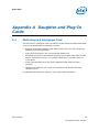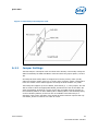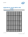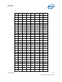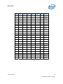
1
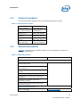
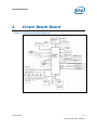
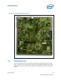
Intel® Atom™ Processor and
Intel® System Controller Hub
US15W Development Kit
User’s Manual
July 2008
Document #: 320264
Revision 1.0
INFORMATION IN THIS DOCUMENT IS PROVIDED IN CONNECTION WITH INTEL® PRODUCTS. NO LICENSE, EXPRESS OR
IMPLIED, BY ESTOPPEL OR OTHERWISE, TO ANY INTELLECTUAL PROPERTY RIGHTS IS GRANTED BY THIS DOCUMENT. EXCEPT
AS PROVIDED IN INTEL'S TERMS AND CONDITIONS OF SALE FOR SUCH PRODUCTS, INTEL ASSUMES NO LIABILITY
WHATSOEVER, AND INTEL DISCLAIMS ANY EXPRESS OR IMPLIED WARRANTY, RELATING TO SALE AND/OR USE OF INTEL
PRODUCTS INCLUDING LIABILITY OR WARRANTIES RELATING TO FITNESS FOR A PARTICULAR PURPOSE, MERCHANTABILITY,
OR INFRINGEMENT OF ANY PATENT, COPYRIGHT OR OTHER INTELLECTUAL PROPERTY RIGHT.
UNLESS OTHERWISE AGREED IN WRITING BY INTEL, THE INTEL PRODUCTS ARE NOT DESIGNED NOR INTENDED FOR ANY
APPLICATION IN WHICH THE FAILURE OF THE INTEL PRODUCT COULD CREATE A SITUATION WHERE PERSONAL INJURY OR
DEATH MAY OCCUR.
Intel may make changes to specifications and product descriptions at any time, without notice. Designers must not rely on the
absence or characteristics of any features or instructions marked "reserved" or "undefined." Intel reserves these for future
definition and shall have no responsibility whatsoever for conflicts or incompatibilities arising from future changes to them. The
information here is subject to change without notice. Do not finalize a design with this information.
The products described in this document may contain design defects or errors known as errata which may cause the product to
deviate from published specifications. Current characterized errata are available on request.
Contact your local Intel sales office or your distributor to obtain the latest specifications and before placing your product order.
This document contains information on products in the design phase of development.
Intel and the Intel logo are trademarks of Intel Corporation in the U.S. and other countries.
*Other names and brands may be claimed as the property of others.
Copyright © 2008 Intel Corporation. All rights reserved.
User’s Manual
2
Document Number: 320264
Contents
1
Introduction .....................................................................................................7
1.1
1.2
1.3
1.4
1.5
2
Crown Beach Board ......................................................................................... 11
2.1
2.2
2.3
2.4
2.5
3
Power Measurement Support ................................................................. 21
Reference Board Summary ............................................................................... 27
4.1
4.2
4.3
4.4
User’s Manual
Getting Started .................................................................................... 12
Overview ............................................................................................ 13
Major Features..................................................................................... 13
Processor Support ................................................................................ 15
2.4.1
Processor Voltage Regulators .................................................... 15
Subsystem Descriptions ........................................................................ 16
2.5.1
Intel® SCH Chipset ................................................................. 16
2.5.2
System Memory ...................................................................... 16
2.5.3
Display .................................................................................. 16
2.5.4
PCI Express* Slots .................................................................. 17
2.5.5
Soft Audio/Soft Modem ............................................................ 17
2.5.6
PATA Storage ......................................................................... 18
2.5.7
USB Connectors ...................................................................... 18
2.5.8
LPC Slot................................................................................. 18
2.5.9
System Management Controller (SMC)/Keyboard Controller (KBC).. 18
2.5.10 EFI Firmware Hub (FWH).......................................................... 19
2.5.11 Trusted Platform Module (TPM) Header....................................... 19
2.5.12 SD/SDIO/MMC ........................................................................ 19
2.5.13 Clocks ................................................................................... 19
2.5.14 Real Time Clock ...................................................................... 19
2.5.15 In-Target Probe (ITP) and Debug Support................................... 20
2.5.16 Power Supply Solution ............................................................. 20
2.5.17 Board Size ............................................................................. 20
2.5.18 Board Technology.................................................................... 20
Power Management......................................................................................... 21
3.1
4
About the Development Kit ......................................................................7
Terminology ..........................................................................................8
Technical Support...................................................................................9
1.3.1
Additional Technical Support .......................................................9
Product Literature ................................................................................ 10
Related Documents .............................................................................. 10
Crown Beach Board Features ................................................................. 27
Connectors.......................................................................................... 27
4.2.1
Back Panel Connectors ............................................................. 28
Configuration Settings........................................................................... 29
4.3.1
Configuration Jumpers/Switches ................................................ 29
BSEL Jumper Settings ........................................................................... 32
3
Document Number: 320264
4.5
4.6
4.7
4.8
4.9
4.10
5
Manual VID Support for CPU .................................................................. 32
Power On and Reset Push Buttons .......................................................... 33
LEDs .................................................................................................. 34
PCI Express* X1 Slots and Mini Card Connectors....................................... 35
4.8.1
Mini Card A connector (J7H1) is enabled by default ...................... 35
4.8.2
Mini Card B connector (J2G1) is disabled by default...................... 36
H8S (JTAG) Programming Headers.......................................................... 36
4.9.1
H8 In-System Programming...................................................... 36
4.9.2
H8 Remote Programming ......................................................... 36
UART Connector ................................................................................... 38
Quick Start .................................................................................................... 39
5.1
5.2
5.3
5.4
Required Peripherals ............................................................................. 39
Graphics Assembly (LVDS Panel) ............................................................ 40
Power Up ............................................................................................ 43
EFI Firmware Updates ........................................................................... 45
Appendix A
Daughter and Plug-In Cards ............................................................................. 46
A.1
Mott Canyon 4 Interposer Card ......................................................................... 46
A.1.1
Jumper Settings ............................................................................................. 47
A.1.2
Firmware Configuration.................................................................................... 49
Appendix B
Intel® MVP-6 VID Codes.................................................................................. 50
Appendix C
External Features............................................................................................ 53
C.1
External Feature Locations ............................................................................... 53
C.1.1
External Feature Location (Front of Chassis) ....................................................... 53
C.1.2
External Feature Location (Rear of Chassis) ........................................................ 54
User’s Manual
4
Document Number: 320264
Figures
Figure
Figure
Figure
Figure
Figure
Figure
Figure
Figure
Figure
Figure
Figure
Figure
Figure
Figure
1. Crown Beach Board Block Diagram ....................................................... 11
2. Crown Beach Board (Top View)............................................................ 12
3. Crown Beach Board Feature Placement ................................................. 27
4. Back Panel Connectors ....................................................................... 28
5. Location of the Configuration Jumpers/Switches ..................................... 29
6. Crown Beach Manual VID .................................................................... 33
7. Crown Beach Power On and Reset Buttons ............................................ 33
8. Crown Beach LEDs ............................................................................. 35
9. Samsung 15 inch (381.00 mm) Panel ................................................... 40
10. Crown Beach Board .......................................................................... 41
11. LVDS Cable Connected to the Crown Beach Board................................. 42
12. Mott Canyon 4 Interposer Card .......................................................... 47
13. Front Chassis View ........................................................................... 53
14. Rear Chassis View with Board Installed ............................................... 54
Tables
Table
Table
Table
Table
Table
Table
Table
Table
Table
Table
Table
Table
Table
Table
Table
Table
User’s Manual
1. Intel Literature Centers........................................................................ 10
2. Related Documents. ............................................................................ 10
3. Crown Beach Feature Set Summary....................................................... 13
4. Crown Beach Supported LVDS Displays .................................................. 17
5. Power Measurement Resistor ................................................................ 21
6. Digital Multi-Meter Comparison ............................................................. 21
7. Crown Beach Voltage Rails ................................................................... 22
8. Back Panel Connectors......................................................................... 28
9. Configuration Jumper/Switches Settings................................................. 30
10. BSEL Jumper Settings........................................................................ 32
11. Crown Beach LEDs ............................................................................ 34
12. PCI Express* Slot 1 Board Rework to Enable Functionality....................... 35
13. Mini Card B Board Rework to Enable Functionality .................................. 36
14. H8 Programming Jumpers .................................................................. 38
15. Mott Canyon 4 Interposer Card Configuration Jumper/Switches................ 48
16 Voltage Identification Definition............................................................ 50
5
Document Number: 320264
Revision History
Document
Number
Revision
Number
Description
394649
1.0
Initial release.
320264
1.0
Release for public posting
§
User’s Manual
6
Document Number: 320264
Introduction
1
Introduction
This manual describes the typical hardware set-up procedures, features, and use of
the evaluation board and other components included in the Intel® Atom™ processor
and Intel® System Controller Hub US15W Development Kit. This reference board
supports the Intel® Atom™ processor and Intel® System Controller Hub (Intel®
SCH).
Note: Read this document in its entirety prior to applying power to the motherboard.
Intel recommends having both the schematic and board present while reading this
document.
The references in this document correlate to reference designators and board
properties of Crown Beach FAB F Customer Reference Board.
This manual is intended to be used with the Development Kit but can also be used to
help bring up a Crown Beach Board, although not all associated peripherals will be
included with a board.
1.1
About the Development Kit
The development kit includes the following:
•
Crown Beach Customer Reference Board with Intel® Atom™ processor Z530
1.6GHz and Intel® System Controller Hub US15W
•
Pre-installed jumpers
•
FWH mounted and flashed with EFI
•
1 GB DDR2 SO-DIMM
•
VGA SDVO ADD2N Card
•
80 GB Hard Drive with MIDINUX Embedded OS
•
DVD-ROM Drive
•
IDE cable
•
Mott Canyon 4 with Intel® High Definition Audio (Intel® HD Audio) card
•
Intel® 82574L Gigabit Ethernet Controller
•
CD with Chipset and Intel® Embedded Graphics Drivers (IEGD)
•
Chassis with ATX power supply
Note: Please refer to Section 5.4 for the location of latest appropriate EFI firmware and
driver updates.
User’s Manual
7
Document Number: 320264
Introduction
Note: Not all peripherals listed will be included with a Crown Beach board.
1.2
Terminology
Term
User’s Manual
Definition
ACPI
Advanced Configuration Power Interface
ADD2
Advanced Digital display 2 card
ADD2R
Advanced Digital display 2 card with PCI-E graphics lane reversed (not
supported on Crown Beach)
CRB
Customer Reference Board
BGA
Ball Grid Array
DDR
Double Data Rate
DMA
Direct Memory Access
Duck Bay 3
PCI Express* interposer card that provides ExpressCard* support for Crown
Beach CRB
EFI
Extensible Firmware Interface
FAE
Field Application Engineer
FSB
Front Side Bus
FWH
Firmware Hub
GPIO
General Purpose Input Output
IDE
Integrated Device Electronics
IEGD
Intel® Embedded Graphics Driver
IMVP
Intel® Mobile Voltage Positioning
Intel® HD Audio
Intel® High Definition Audio
Mott Canyon 4
This Add-in Card enables Intel® HD Audio functionality
Intel® SCH
Intel® System Controller Hub
ITP
In-Target Probe
JEDEC
Joint Electron Device Engineering Council
KBC
Keyboard Controller
LAN
Local Area Network
LED
Light Emitting Diode
LPC
Low Pin Count
LVDS
Low Voltage Differential Signaling
MDC
Mobile Daughter Card
8
Document Number: 320264
Introduction
Term
1.3
Definition
OS
Operating System
PATA
Parallel AT Attachment
PC
Personal Computer
PCB
Printed Circuit Board
PCIe*
PCI Express*
PEG
PCI Express* Graphics
PLL
Phase Lock Loop
PGA
Pin Grid Array
RTC
Real Time Clock
SCH
System Controller Hub
SD
Secure Digital
SDVO
Serial Digital Video Output
SIO
Super Input Output
SMC
System Management Controller
SO-DIMM
Small Outline Dual In-line Memory Module
TPM
Trusted Platform Module
TSSOP
Thin Shrink Small Outline Package
USB
Universal Serial Bus
VGA
Video Graphics Array
VID
Voltage Identification
VR
Voltage Regulator
XDP
Extended Debug Port
Technical Support
Support Services for your hardware and software are provided through the secure
Intel® Premier Support Web site at https://premier.intel.com. After you log on, you
can obtain technical support, review “What’s New,” and download any items required
to maintain the platform. Support is provided through the following product: Dev Kit
(Embedded/Atom/US15W).
1.3.1
Additional Technical Support
If you require additional technical support, please contact your field sales
representative or local distributor.
User’s Manual
9
Document Number: 320264
Introduction
1.4
Product Literature
You can order product literature from the following Intel literature centers.
Table 1. Intel Literature Centers
1.5
U.S and Canada
1-800-548-4725
U.S. (from overseas)
708-296-9333
Europe (U.K.)
44(0)1793-431155
Germany
44(0)1793-421333
France
44(0)1793-421777
Japan (fax only)
81(0)120-47-88-32
Related Documents
Table 2 is a partial list of the available collateral. For the complete list, contact your
local Intel representative.
Table 2. Related Documents.
Document
Document Numbers/ Location
Processor and SCH-Related Documents
Intel® Centrino® Atom™ Processor Technology
Platform Design Guide
Contact your FAE for the latest revision
Menlow Platform Crown Beach Customer Reference
Board Schematic
Menlow Platform – Ballout, Signal, and Mechanical
Package
Intel® Atom™ Processor Z5xx Series Datasheet
Intel® System Controller Hub (Intel® SCH)
Datasheet
Intel® Atom™ Processor Z5xx Series
Specification Update
Intel® System Controller Hub (Intel® SCH)
Specification Update
Firmware-Related Documents
Aptio 4.x Whitepaper
User’s Manual
www.ami.com/aptio/
10
Document Number: 320264
Crown Beach Board
2
Crown Beach Board
Figure 1. Crown Beach Board Block Diagram
User’s Manual
11
Document Number: 320264
Crown Beach Board
Figure 2. Crown Beach Board (Top View)
2.1
Getting Started
This section identifies the key components, features and specifications of the Intel®
Atom™ processor with Intel® System Controller Hub US15W Development Kit. It also
describes how to set up the board for operation. Development software is included in
the kit.
User’s Manual
12
Document Number: 320264
Crown Beach Board
Note: This manual assumes a familiarity with basic concepts involved with installing and
configuring hardware for a PC.
2.2
Overview
The development kit contains a baseboard with an Intel® Atom™ processor Z530,
Intel® System Controller Hub US15W, other system board components and peripheral
connectors.
Note: The evaluation board is shipped in a closed chassis. The user is required to observe
extra precautions if the user opens the chassis for any reason.
Note: Review the document provided with the Development Kit titled Important Safety and
Regulatory Information. This document contains additional safety warnings and
cautions.
2.3
Major Features
Table 3 is a list of the major features for the customer reference board.
Table 3. Crown Beach Feature Set Summary
Feature
Comments
Processor
Intel® Atom™ processor Z530
with 512KB L2 cache
0.55 x 0.52 inch (14 X 13 mm) FCBGA
package with 0.0024 inch (0.6 mm) ball
pitch and 441-pins.
CPU Voltage
Regulator
Intel® Mobile Voltage Positioning
6 (Intel® MVP6)
1 Phase
Chipset
Intel® SCH US15W
0.87 x 0.87 inch (22 X 22-mm) FCBGA
package with 0.0024 inch (0.6-mm) ball
pitch and 1249-pins.
Board
Technology
High Density Interconnect, Type
IV; 1-6-1 stackup
S-G-S-G-Core-G-S-G-S stackup
Board Size
µATX 9.6 x 10.4 inch (243.84 x
264.16 mm)
Doubled-sided placement
Memory
Single top-side SO-DIMM
connector for single-channel,
single or dual rank
Supports up to 2-GB of system memory.
8 SDRAM devices max
One x16 single-channel SDVO
card slot. Supports ADD2N cards.
No integrated VGA support is available
on the Crown Beach CRB.
One LVDS Connector
VGA supported through ADD2N Card.
Graphics
User’s Manual
Crown Beach Board
Implementation
13
Document Number: 320264
Crown Beach Board
Feature
Crown Beach Board
Implementation
Comments
Through a 50-pin cable-up connector
(separate cables required for each
display supported).
LVDS options
Single 24-bit LVDS interface;
Back Light Inverter (BLI) and
LED backlight support
Main Clock
CK540
Integrated CK-SSCD and clock
expansion buffer.
ATA/Storage
PATA66/100
One desktop PATA connector
TSSOP, 64-pinspackage
4 back panel connectors
• Ports [1:0] and [4:3]
3 cable-up
• Ports [5] and [7:6]
USB
8 USB 2.0 ports
One client-mode back panel connector
(mini-B).
• Port [2]
NOTE:
All ports are enabled by default
except port 5. For more
information, refer Section 2.5.7
USB Connectors.
NOTE:
Ports [7:6] are USB 2.0 only.
2 SDIO back panel connectors
• Slot [2:1]
SDIO/MMC
2 ports (Ports 0 and 1), 4-bits
1 port (Port 2), 8-bits
One SDIO backside connector
• Slot [0]
All slots are SDIO Revision 1.1 and MMC
Revision 4.0 compliant
NOTE:
Soft Audio/ Soft
Modem
2 x8 option for cable-up to SDVO
for HDMI+
One Intel® HD Audio MDC
Header
For more information, refer to
Section 2.5.12 SD/SDIO/MMC.
Option for 3.3-V and 1.5-V operation
through jumper.
2 x4 for Mott Canyon 4 support
x1 connector
PCI Express* x1
connector
User’s Manual
Revision 1.0a compliant
2 connectors
NOTE:
Slot 1 is non-functional by
default.
14
Document Number: 320264
Crown Beach Board
Feature
Crown Beach Board
Implementation
Comments
2 connectors.
PCI Express*
Mini Card
connector
NOTE:
NOTE:
PCI Express* signals are
left unconnected on Mini
Card B.
For more information, refer to
Section 2.5.4, PCI Express*
Slots.
LPC
One LPC slot
TPM
Through TPM header (TPM 1.2)
Microcontroller
Renesas Technology* H8S/2117
Includes integrated SPI as an option
FWH
FWH LPC based with socket
40-pin TSSOP socket
SIO
Uses TPM header
Backup only; provides floppy, COM,
Parallel, and PS2
SMC/KBC
Scan matrix headers and PS/2 in
back panel keyboard connector
ACPI compliant through H8S/2117
RTC
Battery-backed real time clock
Port 80 Decode
Supported down on motherboard
with four seven-segment displays
Has an option for cable-up to front panel
of chassis
Desktop Mode
ATX Power Supply
Virtual Battery
SW8A1 switch
Extended Debug Port (XDP)
J1E3 XDP connector
ACPI Compliant
S0
S3
S4
S5
Power Supply
ITP Support
Power
Management
Form Factor
2.4
Mini Card connector A,
functionality is enabled by
default.
No DMA support
–
–
–
–
Power On
Suspend to RAM
Suspend to Disk
Soft Off
Processor Support
The reference board supports the Intel® Atom™ processor Z530 with 512-KB cache in
a 441-pin, FCBGA package. No heatsink is required by this processor during room
temperature ambient operation.
2.4.1
Processor Voltage Regulators
The reference board uses an onboard Intel® MVP6 single-phase regulator for the
processor core supply. The I/O voltage is 1.05 V. See Section 4.5 for VID jumper
location and Appendix B for the VID code table.
User’s Manual
15
Document Number: 320264
Crown Beach Board
2.5
Subsystem Descriptions
Subsystem features refer to the socket and connector locations on the Crown Beach
Board. Socket and connector locations are labeled with a letter-number combination.
Refer to the silkscreen labeling on Crown Beach Board for location detail.
2.5.1
2.5.2
Intel® SCH Chipset
•
Processor interface at 400/533 MHz
•
Single channel DDR2 memory interface running at 400/533 MT/s
•
Two PCI Express* ports, x1
•
Eight USB 2.0 compatible ports
•
One ATAPI-6 (UDMA 100MB/s) IDE channel
•
Intel® HD Audio
•
Three SDIO/MMC interfaces
•
One channel 24-bit LVDS
•
One channel SDVO
•
LPC bus
System Memory
•
Supports a single DDR2 SO-DIMM socket. SO-DIMMs must be un-buffered and
compliant with Raw Cards A or C as defined by JEDEC.
•
Supports 400- or 533-MHz memory bus frequencies.
Note: SO-DIMM support is only provided for validation purposes. The Intel® Centrino®
Atom™ Processor Technology Platform Design Guide provides component
implementations for memory down solutions. The DDR2 SODIMM Architecture’s
Implementation for Intel® System Controller Hub (SCH) US15W whitepaper provides
guidelines for implementing a SO-DIMM solution, although the recommendations are
based on simulation only and have not been validated. It is recommended that
customers validate their designs.
2.5.3
Display
The reference board has two options for displaying video:
•
LVDS – location is J5G2
•
SDVO – location is J7C2
Note: The customer reference board supports single channel LVDS only.
Table 4 is a listing of displays that have been tested with Crown Beach.
User’s Manual
16
Document Number: 320264
Crown Beach Board
Table 4. Crown Beach Supported LVDS Displays
Manufacturer
/Type
2.5.4
Size
Resolution
Back
Light
Aspect
Ratio
Part#
Samsung
4.8 inch
(121.92 mm)
1024 x 600
11 LED
16 x 9
LTS480WS-C01
TMD
5.6 inch
(142.24 mm)
1024 x 600
CCFL
16 x 9
LTD056ET0S
Sharp
7.2 inch
(182.88 mm)
1280 x 768
32 LED
15 x 9
LQ072K1LA08
Samsung
15 inch
(381.00 mm)
1024 x 768
CCFL
4x3
LTN150XG-L08
NEC
8.4 inch
(213.36 mm)
640 x 480
2 CCFL
4x3
NL6448BC26-08D
NEC
9.0 inch
(228.60 mm)
800 x 480
2 CCFL
15 x 9
N8048BC24-06
TMD
11.1 inch
(281.94 mm)
1366 x 768
CCFL
16 x 9
LTD111EXCS
Samsung
15.4 inch
(391.16 mm)
1280 x 800
CCFL
15 x 9
LTN154X5-L06
NOTE:
The protective tape on top of the Crown Beach LVDS connector must be removed prior
to installing an LVDS cable.
NOTE:
VGA output is not directly supported. Customers can use PCI Express*-based discrete,
external 3D graphics cards, or a third-party component available on an ADD2N card
using the SDVO interface.
PCI Express* Slots
•
Two PCI Express* slots x1 for add-in cards.
•
The PCI Express* bus complies with the PCI Express* Rev. 1.0a specification.
Crown Beach provides two PCI Express* Mini Card form factor slots. The PCI Express*
specification pin-out is followed by Mini Card Slot A only and not by Mini Card Slot B.
Mini Card Slot A is enabled by default and to enable Mini Card Slot B, rework needs to
be performed. The slots are not to be used with PCI Express* Mini Card-based
devices. Mini Card A (J7H1) is designed for use with CM100/CM101 cards from
Quanta. Mini Card A can be populated with the Kedron, Echo Peak, or Shirley Peak
wireless cards. Mini Card B (J2G1) is designed for use with Wireless WAN cards from
Sierra Wireless* and Option*.
2.5.5
Soft Audio/Soft Modem
High Definition Soft Audio/Soft Modem functionality is enabled through the Mott
Canyon 4 daughter card. No direct connection is provided for Intel® HD Audio on
User’s Manual
17
Document Number: 320264
Crown Beach Board
Crown Beach. The Mott Canyon 4 card is required to enable the High Definition Audio
functionality. See Appendix A for more information on the Mott Canyon 4 card.
2.5.6
PATA Storage
The Crown Beach Board provides only one desktop, 40-pin, PATA66/100 connector
that supports master and slave devices.
2.5.7
USB Connectors
The Intel® SCH provides eight USB 2.0 ports.
•
Four ports are routed to the back panel’s two stacked USB connectors. USB ports
[1:0] and [4:3] are routed to the back of the chassis.
•
Port 2 is the client-mode connector and is routed to the back of the chassis with a
Mini-B connector.
•
Ports [7:5] are routed to the front panel headers (USB FPIO, Duck Bay, and
Sideband Header) and to the Sideband headers (Duck Bay, Upham USB).
•
For wireless solutions port 0 is also used with stuffing options for the PCI Express*
Mini Card. OC [7:0] # is available for over-current detection.
•
Port 5 is disabled by default due to enabling of PCI Express* Mini Card A Slot.
Note: USB port 0 functionality is impacted if rework is performed to enable the PCI Express*
Mini Card B Slot.
2.5.8
LPC Slot
The H8S/2117 serves as a keyboard controller on the customer reference board.
Note: Other solutions, such as a mouse controller, can be tested in the LPC slot while H8S is
held in reset.
2.5.9
•
LPC slot and sideband header are supported.
•
Docking and DMA are not supported by the Intel® SCH on Crown Beach.
•
Port 80-83 is implemented using the EPM7064AE device down on the motherboard
with 4, seven-segment displays on the LPC bus.
•
An option for connecting the cable to front panel or chassis is available.
System Management Controller (SMC)/Keyboard
Controller (KBC)
Renesas Technology* H8S serves as both SMC and KBC for the platform. The
SMC/KBC controller supports:
User’s Manual
18
Document Number: 320264
Crown Beach Board
•
Two PS/2 ports.
Note: The two PS/2 ports are for a legacy keyboard and mouse. The keyboard plugs into the
bottom port and the mouse plugs into the top port.
2.5.10
•
EMA support
•
Wake/runtime SCI events
•
Power sequencing control
EFI Firmware Hub (FWH)
A TSOP socket houses the flash device (ST Microelectronics P/N# M50FW080) that
stores the system EFI firmware. The EFI firmware can be programmed through a
Microsoft MS-DOS* or Windows*-based utility.
2.5.11
Trusted Platform Module (TPM) Header
Crown Beach implements a header at J9B4 to support TPM 1.2 specification compliant
devices. The same header can be used for legacy connections, allowing other SIO
solutions to provide floppy, COM, Parallel, and PS/2 functionality.
2.5.12
SD/SDIO/MMC
Crown Beach provides three ports with the following features:
2.5.13
•
All ports are SD rev1.1 specification compliant and MMC rev4.0 specification
compliant.
•
All ports operate to 48 MHz. Ports 0 and 1 support 4-bit operation. Port 2 supports
8-bit operation.
•
Slot 2 is also routed (with stuffing options) to the PCI Express* Mini Card for
wireless solutions.
Clocks
The Crown Beach CRB uses a CK-540 clock solution. The BSEL [2:1] signals driven by
the processor are used by the CK-540 to configure the FSB frequency.
2.5.14
Real Time Clock
An on-board battery maintains power to the real time clock (RTC) when in a
mechanical off state (G3 state).
User’s Manual
19
Document Number: 320264
Crown Beach Board
2.5.15
In-Target Probe (ITP) and Debug Support
Crown Beach provides on-board ITP support with an XDP connector. Users can debug
from the reset vector without EFI or OS dependency (up to OS functionality). Ports
80-83 are provided as a troubleshooting tool to monitor POST output during EFI
execution.
Note: ITP requires that the CMC load to configure Poulsbo before register accesses can be
made. The CMC code resides in the FWH on Crown Beach. Thus, it is required that the
FWH flash be programmed and inserted in the FWH socket to use ITP.
Note: Crown Beach does not support ITP 700.
2.5.16
Power Supply Solution
Crown Beach can be powered from an ATX power supply (desktop solution) that
contains all of the voltage regulators necessary to power the system up. Additionally,
virtual battery support is provided through switch SW8A1.
Note: Use an “ATX12V” 1.1 specification compliant power supply regardless of supplier or
wattage level (an "ATX12V" rating means V5 min current =0.1 A, "ATX" V5 min
current = 1.0 A, among other differences). For example, the Sparkle Model No.
FSP300-60BTV meets this requirement and is an ATX12V 1.1 spec compliant power
supply. Depending on the power supply used, Crown Beach may require a load. Crown
Beach provides FETS to assist with this loading through jumpers J4J1 and J5J2, see
Table 9 for jumper settings.
Note: If the power switch on the ATX power supply is used to shut down the system, wait at
least 5 seconds before turning the system on again.
Note: The recommended way to shut down the board is to press and hold the power button
switch (SW3J1) for 5 seconds until the power supply turns off. Using the power supply
switch or pulling the plug out of the wall is not recommended.
2.5.17
Board Size
The reference board form factor is similar to the µATX 9.6 x 10.4 inch (243.84 x
264.16 mm) specification. The back panel jacks may not conform to ATX
specifications.
2.5.18
Board Technology
The Crown Beach reference board uses fine pitched BGA packages, down to
0.0024 inch (0.6 mm) pitch. Type IV high density-interconnect technology is required
for breakout purposes and implemented using a 1-6-1 stack-up (8 layers total).
§
User’s Manual
20
Document Number: 320264
Power Management
3
Power Management
3.1
Power Measurement Support
Power measurement resistors are provided to measure the power on many of the
subsystems.
Table 5. Power Measurement Resistor
NOTE:
Feature
Value
Tolerance
1%
Value
10 mΩ
Intel recommends that larger (~10 mΩ) resistors be stuffed for greater accuracy.
Power on a particular subsystem is calculated using the following formula:
Equation 1.
V2
P=
R
R = value of the sense resistor (typically 0.01 Ω)
V = the voltage difference measured across the sense resistor.
Use a high precision digital multi-meter tool such as the Agilent 34401A digital multimeter. Refer to Table 6 for a comparison of a high-precision, digital multi-meter
(Agilent 34401A) versus a precision, digital multi-meter (Fluke 79).
Table 6. Digital Multi-Meter Comparison
Example System
Sense Resistor Value
Voltage Difference Across Resistor
Calculated Power
User’s Manual
0.01 Ω
1.492 mV (149.2 mA)
0.223 mW
21
Document Number: 320264
Power Management
Agilent 34401A (6½ digit
display)
Fluke 79 (3 digit display)
(±0.0030 % of reading)
±0.09% ±2 digits
Specification
+ (±0.0030 % of range)
Min Voltage displayed
1.49193 mV
1.47 mV
Calculated power
0.22258 mW
0.216 mW
Max voltage displayed
1.49206 mV
1.51 mV
Calculated power
0.22624 mW
0.228 mW
±0.009 %
±0.3 %
Error in power
NOTE:
The precision achieved by using a high precision digital multi-meter versus a normal
digital multi-meter is ~33 times more accurate.
Table 7 summarizes all the power measurement sense resistors located on the Crown
Beach board. All sense resistors are 0.01 Ω unless otherwise noted.
Component
Voltage
Supply
Rail
Ref Des
Resistor
11
SCH
1.8 V
+V1.8
+V1.8_SM_SCH
R5T3
0.01,
1%
DDR2_VR
11
SCH
1.05 V
+V1.05S_SCH
+V1.05S_SCH_VCORE
R6T7
0.01,
1%
VCORE
11
SCH
1.5 V
+V1.5S_SCH
+V1.5S_DLVDS_SCH
R6T9
0.01,
1%
LVDS
11
SCH
3.3 V
+V3.3
+V3.3_SCH_SUS
R6T13
0.01,
1%
SUS
11
SCH
3.3 V
+V3.3S
+V3.3S_SCH
R5T5
0.01,
1%
3.3 V
11
SCH
1.05 V
+V1.05S_VTT
+V1.05S_VTT_SCH
R5U35
0.01,
1%
VTT SCH
11
SCH
1.5 V
+V1.5S
+V1.5S_SCH
R5T6
0.01,
1%
1.5CORE
11
SCH
1.5 V
+V1.5S_SCH
+V1.5S_SDVO_SCH
R6T10
0.01,
1%
SDVO
11
SCH
1.05 V
+V1.05S_VTT
+V1.05S_VTT_CPU
R3U1
0.01,
1%
VTT CPU
User’s Manual
Supply
Power
Topology
Sch Page
Table 7. Crown Beach Voltage Rails
22
Document Number: 320264
Component
Voltage
Supply
Rail
Ref Des
Resistor
11
SCH
1.5 V
+V1.5S_SCH
+V1.5S_PCIe_SCH
R6T6
0.01,
1%
PCIe*
11
SCH
1.8 V
+V1.8
+V1.8_SM_SCH
R5T3
0.01,
1%
DDR2_VR
R6T1
0.01,
1%
PLLs
Supply
Power
Topology
Sch Page
Power Management
12
SCH
1.5 V
+V1.5S_SCH
+V1.5S_DPLLA_SCH,
+V1.5S_DPLLB_SCH,
+V1.5S_PCIePLL_SCH,
+V1.5S_HPLL_SCH,
+V1.5S_AUSBPLL_SCH
14
mini PCIe
1.5 V
+V1.5S
V1.5S_MINIPCIE
R7W9
0.01,
1%
1.5-V mini PCIe
14
mini PCIe
3.3 V
+V3.3
V3.3_MINIPCIE
R9F1
0.01,
1%
3.3-V aux mini
PCIe
15
SDVO
3.3 V
+V3.3S
V3.3S_SDVO
R7C1
0.01,
1%
3.3-V SDVO
16
SDVO
12 V
+V12S
V12S_SDVO
R7B3
0.01,
1%
12-V SDVO
17
LVDS
3.3 V
+V3.3S
V3.3S_LVDS_DDC
R5V21
0.01,
1%
3.3-V
LVDS_DDC
17
LVDS
5V
+V5S
V3.3S_LVDSBKLT
R5V14
0.01,
1%
5-V
LVDS_BCKLT
17
LVDS
12 V
+V12S
V12S_LVDSBKLT
R5V17
0.01,
1%
12-V
LVDS_BCKLT
17
LVDS
3.3 V
+V3.3S
V3.3S_LVDS_VDL
R5V28
0.01,
1%
3.3-V
LVDS_VDL
18
SO_DIMM
1.8 V
+V1.8
+V1.8_DIMM
R6R2
0.01,
1%
SO-DIMM_DDR2
20
FHW
3.3 V
+V3.3S
+V3.3S_FWH
R7H5
0.01,
1%
3.3-V_FWH
21
TPM
5V
+V5
V5_TPM
R8N4
0.01,
1%
5-V TPM
HEADER
21
TPM
3.3 V
+V3.3
V3.3A_TPM
R8P2
0.01,
1%
3.3-V TPM
HEADER
21
MDC,
Audio
3.3 V
+VCCHDA
VCCHDA_R
R8U3
0.01,
1%
3.3V MDC
HEADER
21
MDC,
Audio
1.5 V/
3.3 V
+V1.5S/+V3.3S
VCC_MDC
R9E1
0.01,
1%
1.5-V/3.3-V
MDC HEADER
User’s Manual
23
Document Number: 320264
Component
Voltage
Supply
Rail
Ref Des
Resistor
21
TPM
3.3 V
+V3.3S
V3.3S_TPM
R8P1
0.01,
1%
3.3-V TPM
HEADER
22
PCIe,
slot0
12 V
+V12_SLOTS
V12S_PCIE_SLOT0
R8B1
0.01,
1%
12-V PCIe slot 0
22
PCIe,
slot0
3.3 V
+V3.3_SLOTS
V3.3S_PCIE_ SLOT0
R8C2
0.01,
1%
3.3-V PCIe
slot 0
22
PCIe,
slot1
12 V
+V12_SLOTS
V12S_PCIE_ SLOT1
R8B3
0.01,
1%
12-V PCIe slot 1
22
PCIe,
slot1
3.3 V
+V3.3_SLOTS
V3.3S_PCIE_ SLOT1
R8C5
0.01,
1%
3.3-V PCIe
slot 1
22
PCIe,
slot0
3.3 V
+V3.3
V3.3_PCIE_ SLOT0
R8C6
0.01,
1%
3.3-V AUX PCIe
slot 0
22
PCIe,
slot1
3.3 V
+V3.3
V3.3_PCIE_ SLOT 1
R8C7
0.01,
1%
3.3-V AUX PCIe
slot 1
23
USB
5V
+V5
+V5_USB_P6_P7
R6H2
0.01,
1%
5-V USB Port 6
and 7
23
USB
5V
+V5
+V5_USB_P5
R6H3
0.01,
1%
5-V USB Port 5
24
CK540
3.3 V
+V3.3S
V3.3S_CK505
R8U1
0.01,
1%
3.3-V CK505
25
SDIO1
3.3 V
V3.3S_SDIO_
SLOT1
V3.3S_SDIO1
R5M1
0.01,
1%
3.3-V SDIO 1
25
SDIO0
3.3 V
V3.3S_SDIO_
SLOT0
V3.3S_SDIO0
R6N1
0.01,
1%
3.3-V SDIO 0
25
SDIO2
3.3 V
V3.3S_SDIO_
SLOT2
V3.3S_SDIO2
R4B1
0.01,
1%
3.3-V SDIO 2
27
H8/
Keyboard
3.3 V
+V3.3A
+V3.3A_KBC
R7E2
0.01,
1%
3.3-V
KEYBOARD
31
HD Conn
5V
+V5S
+V5S_PATA
R3J1
0.01,
1%
5-V HD
Connector
R2N1
0.01,
1%
5-V USB Port 0
and 1 (Back
Panel)
R3N1
0.01,
1%
5-V USB Port 3
and 4 (Back
Panel)
32
32
USB
USB
User’s Manual
5V
5V
+V5
+V5
+V5_USB_P0_P1
+V5_USB_P3_P4
Supply
Power
Topology
Sch Page
Power Management
24
Document Number: 320264
+V12S
V1.05B_INPUT
Ref Des
Rail
Supply
Voltage
12 V
R5G1
Supply
Power
Topology
1.05-V
Dual VR
(2)
Resistor
33
Component
Sch Page
Power Management
0.01,
1%
1.05-V Dual VR
(1) -->
+V1.05S_VTT,
+V1.05S_VTT_C
PU
33
1.05-V
Dual VR
(1)
12 V
+V12S
V1.05A_INPUT
R5V9
0.01,
1%
1.05-V Dual VR
(2) -->
+V1.05S_SCH,
+V1.05S_SCH_
VCORE
36
1.8-V VR
(1)
12 V
+V12
V12_1.8_INPUT
R5C16
0.01,
1%
1.8-V VR (1) -> +V1.8
36
0.9-V VR
(2)
12 V
+V0.9S
V0.9S_DDR2
R5R2
0.01,
1%
1.8-V VR (2) -> +V0.9
38
1.5-V VR
3.3 V
+V3.3S
V3.3S_1.5_INPUT
R5F18
0.01,
1%
1.5-V VR -->
+V1.5S
39
3.3-V VR
3.3 V
+V3.3A
51120VBST2_LR
R4G14
0.002,
1%
3.3-V VR
39
3.3-V VR
3.3 V
+V12A
V12A_3.3A_INPUT
R3W1
0.01,
1%
3.3-V VR
39
5-V VR
5V
+V12A
V12A_5A_INPUT
R4W4
0.01,
1%
5-V VR
39
5V VR
5V
+V5A
51120_+V5A_MBL_QL
R4H3
0.002,
1%
5-V VR
41
Intel®
MVP-6
5V
+V5S
V5S_IMVP_IN
R3C9
0.01,
1%
42
Intel®
MVP-6
12 V
+V12S_CPU
V12_CPU_PHASE
R2R8
44
ATX Conn
12 V
+V12A
+V12_ATX
R1J3
0.002,
5%
45
S4
5V
+V5
+V5A
R4G9
0.01,
1%
5 V, S4
45
S4
3.3 V
+V3.3
+V3.3A
R4G12
0.01,
1%
3.3 V, S4
45
S3
5V
+V5S
+V5A
R4F4
0.002,
1%
45
S3
3.3 V
+V3.3S
+V3.3A
R4G10
0.01,
1%
User’s Manual
0.002,
5%
Intel MVP-6
Intel MVP-6
12-V ATX conn
5 V, S3
3.3 V, S3
25
Document Number: 320264
Component
Voltage
Supply
Rail
Ref Des
Resistor
45
S3
12 V
+V12S
+V12S_CPU
R1H2
0.01,
1%
Supply
Power
Topology
Sch Page
Power Management
12 V, S3
§
User’s Manual
26
Document Number: 320264
Reference Board Summary
4
Reference Board Summary
4.1
Crown Beach Board Features
Figure 3. Crown Beach Board Feature Placement
Note: The actual labeling on the board is Port 80 and 81.
4.2
Connectors
Many of the connectors supply operating voltages of (+5V DC and +12V DC) to
devices inside the computer chassis, such as fans and internal peripherals.
Caution:
User’s Manual
Most of these connectors are not over-current protected. Do not use these connectors
for powering devices external to the computer chassis. A fault in the load presented
27
Document Number: 320264
Reference Board Summary
by the external devices could damage the computer, the interconnecting cable, or the
attached external device.
4.2.1
Back Panel Connectors
This section describes the board’s connectors. Figure 4 shows the location of the back
panel connectors on the board.
Figure 4. Back Panel Connectors
Note: Connector J1A1 USB Client is a USB 2.0 Mini-B connector.
Table 8. Back Panel Connectors
Ref Des
Description
Back
Panel
Connector
PS/2 connector
J1A2
Top: Mouse
Bottom: Keyboard
J1A1
USB Client connector, Port 2
USB Host ports with over-current detection
J2A1
Top: Port 0
Bottom : Port 1
USB Host ports with over-current detection
User’s Manual
J3A1
Top: Port 4
Bottom : Port 3
J4B1
8-bit SD/SDIO/MMC Slot 2
J5B1
4-bit SD/SDIO/MMC Slot 1
28
Document Number: 320264
Reference Board Summary
4.3
Configuration Settings
4.3.1
Configuration Jumpers/Switches
Caution:
Do not move jumpers with the power on. Switches may be moved while power is on.
Always turn off the power and unplug the power cord from the computer before
changing jumper settings. Otherwise, damage to the board could occur.
Figure 5 shows the location of the major configuration jumpers and switches. Table 9
summarizes the jumpers and switches and gives their default and optional settings.
The Crown Beach board is shipped with the jumpers and switches shunted in the
default locations.
Figure 5. Location of the Configuration Jumpers/Switches
User’s Manual
29
Document Number: 320264
Reference Board Summary
Table 9. Configuration Jumper/Switches Settings
#
Description
Default Setting1
Reference
Designator
J8E1
1a
Remote H8
Programming
Open
1-2 (Short) – to
program H8 3
1b
Remote H8
Programming
(BB_PROG)
1-2 – normal operation
1-x – link the Host Unit
to On Board H8
J8D4
2-3 (DOWN) – Virtual
Battery switch is pulled
low. This enables the
virtual battery and the
system acts as if it is
running from a battery
source
SW8A1
1-2 (IN) – Override
switch SW9A2 condition.
System will always act
as if it is running from a
battery source
J8A1
1-2 (IN) - Override
switch condition, pulled
low
J9A1
2-3 (DOWN) – LID
switch is pulled low
SW9A1
1-2 (UP) – normal
operation
2
Virtual Battery
Switch
3
Virtual Battery
Jumper
4
Lid Jumper
Virtual Battery switch
is pulled high
(disabled). The system
acts as if it is running
on AC power
1-x (OUT) – normal
operation
Virtual battery status
is controlled by SW9A2
1-x (OUT) – normal
operation
No effect on circuit.
1-2 (UP) – normal
operation
J8E4
5
Lid Switch
6
Clear RTC
1-x (OUT) – normal
operation
1-2 (IN) to clear CMOS
J4H1
7
Force Shutdown
No Stuff
Reserved
J7G1
8a
BSEL0 Setting
No Stuff
Reserved
J8G2
8b
BSEL1 Setting
1-2 – Processor BSEL
Select
OUT – 400 MHz
8c
BSEL2 Setting
1-2 – Processor BSEL
Select
2-3 – 400 MHz
Manual VIDs:
IN – normal operation
VID
VID
VID
VID
VID
VID
VID
(1-2)
(3-4)
(5-6)
(7-8)
(9-10)
(11-12)
(13-14)
9a
User’s Manual
Optional Setting
6
5
4
3
2
1
0
(1-2)
(3-4)
(5-6)
(7-8)
(9-10)
(11-12)
(13-14)
LID switch is pulled
high
OUT – 533 MHz
OUT – 533 MHz
OUT – Refer to
Section 4.5 and
Appendix B
2
2
J8G3
J9G3
J1B1
30
Document Number: 320264
Reference Board Summary
#
Description
Default Setting1
Optional Setting
15-16 (IN) – Override to
allow manual VID
operation
Reference
Designator
9b
VID CPU Override4
(15-16)
10a
CFG0 Setting
Refer to Section 4.4
J6F1
10b
CFG1 Setting
Refer to Section 4.4
J7F2
11
Reserved
OUT – normal
operation
Reserved
J7F1
12
PS_ON#
1-2 – normal operation
2-3 - Reserved
J7H4
13
5V FET Load
Disable
1-X (OUT) load
1-2 (IN) no load
J4J1
14
12V FET Load
Disable
1-2 (IN) no load
1-X (OUT) load
J5J2
OUT – normal
operation
J1B1
NOTES:
1.
A jumper consists of two or more pins mounted on the motherboard. When a jumper
cap is placed over two pins, it is designated as IN. When there are more than two pins
on the jumper, the pins to be shorted are indicated as 1–2 (to short pin 1 to pin 2), 2–
3 (to short pin 2 to pin 3), etc. When no jumper cap is to be placed on the jumper, it is
designated as OUT.
2.
When a switch is designated as 1–2, the switch slide is positioned such that pins 1 and
2 are shorted together.
3.
H8 Jumper programming procedure is shown in Section 4.9.
Note: VID Override Jumper settings are shown in Appendix B.
User’s Manual
31
Document Number: 320264
Reference Board Summary
4.4
BSEL Jumper Settings
The jumper settings in Table 10 are provided to accommodate frequency selection for
the processor. The CK-540 clock chip accepts two signals from the Intel® Atom™
processor.
Table 10. BSEL Jumper Settings
Processor
CPU
Processor driven
400
FSB
Speed
(MHz)
(Host CLK = 100 MHz)
Default
533
Intel® SCH
Override
Graphics
J8G3 Æ 1-2
J9G3 Æ 1-2
No override
See note.
J8G3Æ Open
CPU BSEL 1=0
J6F1 Æ 2-3
J9G3Æ 2-3
CPU BSEL 2=1
J7F2 Æ 2-3
J8G3Æ Open
CPU BSEL 1=0
J6F1 Æ 1-2
J9G3Æ Open
CPU BSEL 2=0
J7F2 Æ 2-3
(Host CLK = 133 MHz)
NOTE:
4.5
Jumpers J7F2 and J6F1 must be set according to the FSB frequency to ensure 200-MHz
operation.
Manual VID Support for CPU
The Crown Beach supports manual VID operation for the processor VR. A header
(J1B1) is provided to incorporate “VID override”. VID override allows for overriding
the CPU VID outputs to the CPU VCC_CORE VR. The intent of the “VID override”
circuit is to enable debugging and testing. See Appendix B for the VID code table.
Note: When manually overriding the VID outputs, an open jumper position will result in logic
‘1’ on the corresponding VID signal. Closing the jumper position will result in logic ‘0’
on the corresponding VID signal.
User’s Manual
32
Document Number: 320264
Reference Board Summary
Figure 6. Crown Beach Manual VID
4.6
Power On and Reset Push Buttons
The Crown Beach board has two pushbuttons, POWER and RESET. The POWER button
releases power to the entire board causing the board to boot. The RESET button
forces all systems to warm reset.
The two buttons are located near the ATX-Power connector. The POWER button is
located at SW3J1 and the RESET button is located at SW2J1. See Figure 7.
Figure 7. Crown Beach Power On and Reset Buttons
User’s Manual
33
Document Number: 320264
Reference Board Summary
4.7
LEDs
Figure 8 reveals the location of the LEDs and Table 11 describes the function of the
LEDs and their reference designators
Table 11. Crown Beach LEDs
#
User’s Manual
Function
Reference Designator
1
Keyboard number lock
CR8E2
2
Keyboard scroll lock
CR8E3
3
Keyboard caps lock
CR8E1
4
System State S0
CR8E7
5
System State S3 Cold
CR7E1
6
System State S4/S5
CR8E5
7
PATA Activity
CR6J1
8
VID Setting 0
CR1C1
9
VID Setting 1
CR1C2
10
VID Setting 2
CR1D1
11
VID Setting 3
CR1D2
12
VID Setting 4
CR1D3
13
VID Setting 5
CR1D4
14
VID Setting 6
CR1D5
34
Document Number: 320264
Reference Board Summary
Figure 8. Crown Beach LEDs
4.8
PCI Express* X1 Slots and Mini Card Connectors
4.8.1
Mini Card A connector (J7H1) is enabled by default
To enable PCI Express* Slot 1 (J8C1) Mini Card A (J7H1) must be redirected to Slot 1.
Table 12. PCI Express* Slot 1 Board Rework to Enable Functionality
Rework
Impacted components
Remove – R6D1, R6D3, R6E2, R6E3,
R8F19, R8F21
Enable Slot 1
Populate 0 Ohms – R6D2, R6D4,
R6E1, R6E4
Populate 33 Ohms - R8F22, R8F20
User’s Manual
Comments
Rework provides proper connectivity for PCI
Express* Slot 1. Refer to the Mini Card A
sheet of the Crown Beach Schematics and
layout for details.
35
Document Number: 320264
Reference Board Summary
4.8.2
Mini Card B connector (J2G1) is disabled by default
To enable the port for Mini Card B (J2G1), PCI Express* Slot 0 (J7C1) and USB Port 0
(J2A1) devices must be redirected to the Mini Card B connector.
Table 13. Mini Card B Board Rework to Enable Functionality
Rework
Impacted components
Remove – R2B2, R2B4
Enable Mini Card B
Populate – R2B3, R2B5, R8Y7,
R8W19, R8Y2, R8Y1,
R8W22
Comments
Rework provides proper USB and SIM card
connectivity for wireless WAN cards from
Sierra Wireless* and Option* only. However,
there are a significant number of additional
no-stuff components that must be populated
for full functionality. Refer to the Mini Card B
sheet of the Crown Beach Schematics for
details.
USB Port 0 functionality through connector
J2A1 is disabled when Mini Card B is enabled.
4.9
H8S (JTAG) Programming Headers
The microcontroller firmware for system management/keyboard/mouse control can be
upgraded in two ways:
4.9.1
1.
By use of a special MS-DOS utility (in-circuit).
2.
By use of an external computer connected (remotely) to the system through the
serial port on the board.
H8 In-System Programming
If the user chooses in-system programming of the Crown Beach board, ensure that
the following files are available on the DOS bootable media:
1.
EC_xx.bin
- EC application
2.
Fcntl.bin
- Renesas Technology* flash algorithm data file
3.
Kscflash.exe
- downloader
Boot to a DOS environment on the Crown Beach machine and type “kscflash
ec_xx.bin” to begin programming the EC.
4.9.2
H8 Remote Programming
If the user chooses to use an external computer (remote programming) connected to
the system through the serial port, there are three jumpers that must be set correctly.
Refer to Table 9 for a summary of these jumpers and refer to the Crown Beach
schematic for the location of each jumper.
The sequence of events necessary to program the H8 is as follows:
User’s Manual
36
Document Number: 320264
Reference Board Summary
1.
Extract all files (keep them in the same folder) to a single directory of your choice
on the host machine or on a floppy disk (recommended).
2.
Connect a NULL modem cable to the serial ports of each platform (host and unit to
be flashed).
3.
With the board powered off, move the jumpers listed in Table 14 to the
programming stuffing option.
4.
Attach an ATX power supply to the system and power up the board.
5.
Boot the host system into a DOS environment using DOS bootable media
6.
Install a serial port onto the target board header J9F1.
7.
Hook up a null modem cable.
8.
From the directory where you extracted the files on the host machine, run the
“kscflash ec_xx.bin /remote” command to program H8 through the serial port.
9.
Follow the flash utility instructions.
10. With the board powered off, return the jumpers to their default settings.
Note: Make sure the board is not powered on, and the power supply is disconnected before
moving any of the jumpers.
User’s Manual
37
Document Number: 320264
Reference Board Summary
Table 14. H8 Programming Jumpers
#
Jumper
1
Remote H8
Programming
(BB_PROG)
2
Remote H8
Programming
(JTAG)
4.10
Reference
Designator
J8D4
J8E1
J8E4
Default Stuffing Option
Programming Stuffing Option
1-2 – normal operation
(Default)
1-x – link the Host Unit to On Board H8
Remove Power Supply from the
system.
1-X (Open)
1-2 (Short) – to program H8
UART Connector
UART functionality is added to the Intel® SCH SKU. Use connector J9G6 for UART
connectivity.
§
User’s Manual
38
Document Number: 320264
Quick Start
5
Quick Start
The CRB is configured in a protective chassis. To access to the board with chassis
open, use caution when configuring the hardware and observe proper safety cautions
and warnings. The following sections summarize the necessary hardware and poweron instructions.
Caution:
Always turn off the power and unplug the power cord before entering protective
chassis. The user is required to observe extra precautions when handling and
operating the system.
Note: Review the document provided with the Development Kit titled Important Safety and
Regulatory Information. This document contains addition safety warnings and
cautions.
5.1
Required Peripherals
•
DDR2 400- or 533-MHz SDRAM SO-DIMM
•
ATX power supply
•
Keyboard and mouse
•
Hard drive
•
Hard drive cable
•
Graphics option
Note: PCI Express* and ADD2N (VGA output provided) graphics card “Quick Start” options
are not included in this document.
User’s Manual
39
Document Number: 320264
Quick Start
5.2
Graphics Assembly (LVDS Panel)
Figure 9. Samsung 15 inch (381.00 mm) Panel
LCD Panel
LVDS Cable
User’s Manual
40
Document Number: 320264
Quick Start
Complete the following steps to operate the reference board with the Samsung 15
inch (381.00 mm), 1024 x 768 (LTN150XG-L08) Panel. These steps will change if
using different displays.
Step 1: Remove the Orange/Yellow tape from the Crown Beach Board.
Figure 10. Crown Beach Board
User’s Manual
41
Document Number: 320264
Quick Start
Step 2: Attach the LVDS cable to the Samsung panel and Crown Beach Board.
Figure 11. LVDS Cable Connected to the Crown Beach Board
User’s Manual
42
Document Number: 320264
Quick Start
Step 3: Connect the Back Light Inverter (BLI) to the Samsung panel and LVDS cable.
Step 4: In the Firmware Configuration Menu, go to: Chipset -> North Bridge
Configuration -> Boot Display Configuration -> Flat Panel Type to 1024x768
Samsung 15 inch (381.00 mm).
5.3
Power Up
Complete the following steps to operate the reference board.
1.
Place a DDR2 SO-DIMM in memory socket J6D1.
2.
Install or verify the configuration jumpers as shown in Section 4.3.1.
3.
Verify presence of RTC battery in Battery Holder at XBT5H1.
4.
Plug in an ATX power supply into connectors J3J2 and J1J1; the connectors are
keyed and will only fit in one position.
5.
Connect a hard drive to connector J4J3 using a PATA cable (red stripe toward pin
1). Connect ATX power to hard drive.
6.
Connect a PS/2 keyboard to connector J1A2 (bottom)
7.
Connect a PS/2 mouse to connector J1A2 (top)
Note: You can reverse the connections of the keyboard and mouse.
8.
User’s Manual
If internal graphics are not used, plug a PCI Express* Graphics card in the PCI-E
x1 slot J7C1 and connect a monitor to the card.
43
Document Number: 320264
Quick Start
Note: VGA output is provided by using the ADD2N card on the SDVO port.
The following steps are optional depending on the user’s needs:
1.
Attach the Mott Canyon 4 MDC to the MDC header at J9E2 and J9E3. An Intel®
HD Audio card can be piggybacked onto the Mott Canyon 4 card to provide soft
audio and soft modem functionality. Adapter cables, speakers, or a phone line for
a modem may be needed, depending on the specific card used.
2.
Attach a desktop CD-ROM (or mobile CD-ROM with adapter) with cable to
connector J4J3 (red stripe toward pin 1). Attach a power cable to connector J3J1
or from an ATX power supply. If two IDE devices are used on the same channel,
one must be set to master and one must be set to slave. Check the operating
instructions for the IDE devices.
3.
If desired, connect a USB floppy to one of the USB connectors.
Powering Up the Board
1.
Press the power button located at SW3J1.
2.
As the system boots, press F2 on the keyboard to enter the Firmware setup
screen.
3.
Check time, date, and configuration settings. For most users the default settings
should be sufficient for the initial bring-up.
4.
Press F10 to save and exit the Firmware setup.
5.
The system reboots and is ready for use.
Note: If the board does not power up completely, the Port 80 code on the 7-segment
displays (CR7B2 and CR7B3) may provide insight into the issue.
Powering Down the Board
There are three options for powering-down the Crown Beach CRB:
1.
Use OS-controlled shutdown through the Windows Start menu (or equivalent)
2.
Press the power button on the motherboard at SW3J1 to begin power-down.
3.
If the system is hung, it is possible to asynchronously shut the system down by
holding the power button down continuously for 4 seconds.
Note: Intel does not recommend powering down the board by shutting off power at the ATX
power supply.
User’s Manual
44
Document Number: 320264
Quick Start
5.4
EFI Firmware Updates
To update the EFI image to a newer release, use the EFI binary image and AFUDOS
utility included in the latest embedded Intel® Atom™ processor technology firmware
kit.
Do the following:
1.
Boot into a DOS environment using media which is DOS-bootable and includes
AFUDOS and the ROM file.
2.
Run the following command (where ‘xxx’ corresponds to the EFI revision number
and ‘y’ = A [Alpha], B [BETA], G [Gold]): AFUDOS.exe CBCHyxxx.rom /p /b
/n /x /c
3.
Reboot the system.
§
User’s Manual
45
Document Number: 320264
Quick Start
Appendix A Daughter and Plug-In
Cards
A.1
Mott Canyon 4 Interposer Card
The Mott Canyon 4 Interposer card is provided to enable Intel® HD Audio functionality
on the Crown Beach Board. Functionality includes:
•
Supports three Mobile Daughter Card (MDC) headers and up to two Intel® High
Definition codecs simultaneously
•
Plugs into a PCI Express* slot—for mechanical stability only
•
Electrically connected to the platform through a 26-pin ribbon cable from the Mott
Canyon 4 Interposer card to a 2 x 8 header (J9E2) and 2 x 4 header (J9E3) on
Crown Beach
•
Intel® HD Audio MDC cards may require sideband signal cables for proper
operation
•
Headers on the Mott Canyon 4 card are provided for both modem and audio
sideband signals
For additional information see Sheet 21 of the Crown Beach schematics.
User’s Manual
46
Document Number: 320264
Quick Start
Figure 12. Mott Canyon 4 Interposer Card
A.1.1
Jumper Settings
The Mott Canyon 4 Interposer card can select either Primary or Secondary Intel® HD
Audio functionality for MDC0 and MDC1 connectors with two jumper options, J16 and
J25.
In Intel® HD Audio mode, MDC0 is designed to house the primary codec (usually
audio but could be modem if there is no audio) and if necessary, MDC1 is designed to
house the modem codec. MDC2 supports an Intel® HD Audio modem-only codec.
The Intel® SCH supports up to two SDATA_IN channels (0, 1). Two jumpers, J27 and
J28 are used to select the appropriate SDATA_IN channels for each of the MDCs. Be
aware that SDATA_IN channels 1 and 2 can be also overridden through jumpers on
the evaluation platform. If either SDATA_IN1 or SDATA_IN2 are not shunted properly
on the evaluation platform, these lines are not available to the Mott Canyon 4
Interposer card. Proper operation of the Intel® HD Audio interface requires that only
one SDATA_IN line is routed to one codec at a time.
User’s Manual
47
Document Number: 320264
Quick Start
Table 15 summarizes the default and optional settings for the jumper/switches.
Table 15. Mott Canyon 4 Interposer Card Configuration Jumper/Switches
#
Description
1
ACZ_SD_0 Destination
(MDC-0-1-2)
2
ACZ_SD_1 Destination
(MDC-0-1-2)
Reference
Designator
Default Setting
Optional Setting
1-2 for MDC0 codec A
3-4 for MDC0 codec B
5-6 for MDC1 codec A
7-8 for MDC1 codec B
9-10 for MDC2 codec A
J27
5-6 for MDC1 codec A
1-2 for MDC0 codec A
3-4 for MDC0 codec B
7-8 for MDC1 codec B
9-10 for MDC2 codec A
J28
3
ACZ_SD_2 Destination
(MDC-0-1-2)
9-10 for MDC2 codec A
1-2
3-4
5-6
7-8
J29
4
MDC0 Primary Jumper
2-3 for primary
1-2 for secondary
J16
5
MDC1 Primary Jumper
2-3 for primary
1-2 for secondary
J25
6
3.3-V Power Option
1-2 for mobile
2-3 for desktop
J24
7
5.0-V Power Option
1-2 for mobile
2-3 for desktop
J32
8
MDC0 Docking
Emulation (Switch
Enable)
1-2 for off
2-3 for on
J33
9
MDC0 Docking
Emulation
(Dock_RST#)
1-2 for normal
2-3 for docking emulation
J26
User’s Manual
for
for
for
for
MDC0
MDC0
MDC1
MDC1
codec
codec
codec
codec
A
B
A
B
48
Document Number: 320264
Quick Start
A.1.2
Firmware Configuration
To enable Mott Canyon 4 Interposer card High Definition Audio functionality, the
Firmware settings may need to be modified.
To modify the Firmware settings do the following:
1.
With the system powered off, press the power button located at SW3J1.
2.
As the system boots, press DEL on the keyboard to enter the Firmware setup
screen.
3.
Move the top cursor (using the sideways arrow keys) to Chipset.
4.
Move the screen cursor (using the up/down arrow keys) to South Bridge
Configuration and press the Enter key.
5.
Move the screen cursor to Audio Controller Codec and press the Enter key.
6.
Select Azalia for the audio codec.
7.
Save the settings and exit the Firmware.
§
User’s Manual
49
Document Number: 320264
Quick Start
Appendix B Intel® MVP-6 VID
Codes
Table 16 Voltage Identification Definition
User’s Manual
VID6
VID5
VID4
VID3
VID2
VID1
VID0
VCC (V)
0
0
1
1
0
0
0
1.2000
0
0
1
1
0
0
1
1.1875
0
0
1
1
0
1
0
1.1750
0
0
1
1
0
1
1
1.1625
0
0
1
1
1
0
0
1.1500
0
0
1
1
1
0
1
1.1375
0
0
1
1
1
1
0
1.1250
0
0
1
1
1
1
1
1.1125
0
1
0
0
0
0
0
1.1000
0
1
0
0
0
0
1
1.0875
0
1
0
0
0
1
0
1.0750
0
1
0
0
0
1
1
1.0625
0
1
0
0
1
0
0
1.0500
0
1
0
0
1
0
1
1.0375
0
1
0
0
1
1
0
1.0250
0
1
0
0
1
1
1
1.0125
0
1
0
1
0
0
0
1.0000
0
1
0
1
0
0
1
0.9875
0
1
0
1
0
1
0
0.9750
0
1
0
1
0
1
1
0.9625
0
1
0
1
1
0
0
0.9500
0
1
0
1
1
0
1
0.9375
50
Document Number: 320264
Quick Start
User’s Manual
VID6
VID5
VID4
VID3
VID2
VID1
VID0
VCC (V)
0
1
0
1
1
1
0
0.9250
0
1
0
1
1
1
1
0.9125
0
1
1
0
0
0
0
0.9000
0
1
1
0
0
0
1
0.8875
0
1
1
0
0
1
0
0.8750
0
1
1
0
0
1
1
0.8625
0
1
1
0
1
0
0
0.8500
0
1
1
0
1
0
1
0.8375
0
1
1
0
1
1
0
0.8250
0
1
1
0
1
1
1
0.8125
0
1
1
1
0
0
0
0.8000
0
1
1
1
0
0
1
0.7875
0
1
1
1
0
1
0
0.7750
0
1
1
1
0
1
1
0.7625
0
1
1
1
1
0
0
0.7500
0
1
1
1
1
0
1
0.7375
0
1
1
1
1
1
0
0.7250
0
1
1
1
1
1
1
0.7125
1
0
0
0
0
0
0
0.7000
1
0
0
0
0
0
1
0.6875
1
0
0
0
0
1
0
0.6750
1
0
0
0
0
1
1
0.6625
1
0
0
0
1
0
0
0.6500
1
0
0
0
1
0
1
0.6375
1
0
0
0
1
1
0
0.6250
1
0
0
0
1
1
1
0.6125
1
0
0
1
0
0
0
0.6000
1
0
0
1
0
0
1
0.5875
1
0
0
1
0
1
0
0.5750
51
Document Number: 320264
Quick Start
VID6
VID5
VID4
VID3
VID2
VID1
VID0
VCC (V)
1
0
0
1
0
1
1
0.5625
1
0
0
1
1
0
0
0.5500
1
0
0
1
1
0
1
0.5375
1
0
0
1
1
1
0
0.5250
1
0
0
1
1
1
1
0.5125
1
0
1
0
0
0
0
0.5000
1
0
1
0
0
0
1
0.4875
1
0
1
0
0
1
0
0.4750
1
0
1
0
0
1
1
0.4625
1
0
1
0
1
0
0
0.4500
1
0
1
0
1
0
1
0.4375
1
0
1
0
1
1
0
0.4250
1
0
1
0
1
1
1
0.4125
1
0
1
1
0
0
0
0.4000
1
0
1
1
0
0
1
0.3875
1
0
1
1
0
1
0
0.3750
1
0
1
1
0
1
1
0.3625
1
0
1
1
1
0
0
0.3500
1
0
1
1
1
0
1
0.3375
1
0
1
1
1
1
0
0.3250
1
0
1
1
1
1
1
0.3125
1
1
0
0
0
0
0
0.3000
§
User’s Manual
52
Document Number: 320264
Quick Start
Appendix C External Features
C.1
External Feature Locations
The section describes the modifications that directly support the Crown Beach
CRB motherboard and the general chassis information.
C.1.1
External Feature Location (Front of Chassis)
Figure 13. Front Chassis View
1
5
2
3
4
User’s Manual
1.
Power switch
2.
Power LED
3.
HDD Activity LED
4.
Reset switch
53
Document Number: 320264
Quick Start
5.
C.1.2
DVD-ROM Drive
External Feature Location (Rear of Chassis)
Figure 14. Rear Chassis View with Board Installed
5
1
2
3
4
1.
PS/2 mouse port
2.
USB C port
3.
2 Dual stack USB―USB 2.0 ports
4.
SDIO ports
5.
PS/2 keyboard port
§
User’s Manual
54
Document Number: 320264