1
For air conditioners:
:
ACI/AOU-35HPR1
ACI/AOU-53HPR1
ACI/AOU-71HPR1
ACI/AOU-105HPS3
ACI/AOU-140HPS3
lnstall according to this installation instructions strictly.
lf installation is defective, it will cause water leakage,
electrical shock and fire.
CONTENTS
When installing the unit in a small room, take measures
against to keep refrigerant concentration from exceeding
allowable safety limits in the event of refrigerant leakage.
PRECAUTI0NS...........
Contact the place of purchase for more information.
Excessive refrigerant in a closed ambient can lead to oxygen
deficiency.
Use the attached accessories parts and specified parts
for installation.
otherwise, it will cause the set to fall, water leakage,
electrical shock and fire.
lnstall at a strong and firm location which is able to
withstand the set's weight.
lf the strength is not enough or installation is not properly
17
done, the set will drop to cause injury.
The appliance must be installed 2.3m above floor.
The appliance shall not be installed in the laundry.
Before obtaining access to terminals, all supply circuits
must be disconnected.
1. PRECAUTIONS
The appliance must be positioned so that the plug is
accessible.
Be sure to be in conformity with the local, national and
international laws and regulations.
Read "PRECAUTIONS" carefully before installation.
The following precautions include important safty items.
Observe them and never forget.
Keep this manual with the owner's manual in a handy place
for future reference.
The safty precautions listed here are divided into two categories.
WARNING
Failure to observe a warning may result in death.
CAUTION
Failure to observe
a caution may result in injury or
damage to the equipment.
The enclosure of the appliance shall be marked by word,
or by symbols, with the direction of the fluid flow.
For electrical work, follow the local national wiring
standard, regulation and this installation instructions. An
independent circuit and single outlet must be used.
lf
electrical circuit capacity
is not enough or defect
in
electrical work, it will cause electrical shock or fire.
Use the specified cable and connect tightly and clamp
the cable so that no external force will be acted on the
terminal.
lf connection or fixing is not perfect, it will cause heat-up or
fire at the connection.
Wiring routing must be properly arranged so that control
board cover is fixed properly.
lf control board cover is not fixed perfectly, it will cause
heat-up at connection point of terminal, fire or electrical
shock.
lf the supply cord is damaged, it must be replaced by the
manufacture or its service agent or a similarly qualified
person an order to avoid a hazard.
After completing the installation, make sure that the unit operates
properly during the start-up operation. Please inshuct the customer
on how tg operate the unit and keep it maintained.Also, inform
customers that they should store this installation manual along with
An all-pole disconnection switch having a contact
separation, of at least 3mm in all poles should be
the owner's manual for future reference.
When carrying out piping connection, take care not to let
air substances go into refrigeration cycle.
Otherwise, it Will cause lower capacity, abnormal high
WARNING
connected in fixed wiring.
pressure in the refrigeration cycle, explosion and injury.
Be sure only trained and qualified service personnel to
install, repair or service the equipment.
Do not modify the length of the power supply cord or use
of extension cord, and do not share the single outlet with
other electrical appliances.
lmproper'installation, repair, and maintenance may result in
electric shocks, short-circuit, leaks, fire or other damage to
Othenrvise, il will cause fire or electrical shock.
the equipment.
Carry out the specified installation work after taking into
account strong winds, typhoons or earthquakes.
lmproper installation work may result in the equipment falling
and causing accidents.
installation manual
1
lf the refrigerant leaks during installation, ventilate
the
area immediatelY.
ioxic gas may Ue produced if the refrigerant comes into the
place contacting with fire.
please
The temperature of refrigerant circuit will be high'
keep the interconnection cable away from the copper
tube.
After completing the installation work, check that the
refrigerant does not leak.
if the refrigerant leaks inlo the
as a
room ind comes into contact with a source of fire' such
fan heater, stove or cooker.
Toxic- gas may be produced
INSTALLATION INFORMATION
2.
r
To install properly, please read this "installation manual" at
first.
The air conditioner must be installed by qualified persons'
When installing the indoor unit or its tubing, please follow
this manual as strictly as possible.
lf the air conditioner is installed on a metal part of
relevant standards to electrical appliances'
When all the installation work is finished, please turn on
the power only after a thorough check'
CAUTION
Regret for no further announcement if there is any change
of this manual caused by product improvement'
Ground the air conditioner
pipes'
Do not connect the ground wire to gas or water
wire'lncomplete
ground
lightning rod or a telephone
grounding may result in electric shocks'
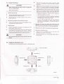
INSTALLATION ORDER
I
Select the location;
electric shocks.
I
lnstall the indoor unit;
the indoor
Gonneict the outdoor unit wires , then connect
I
lnstall the outdoor unit;
unit wires.
with the
You are not allow to connect the air conditioner
po*"t .ort"" until wiring and piping the air conditioner is
I
lnstall the connecting PiPe;
done.
I
Connect the drain PiPe;
r
Wiring;
I
Testoperation.
in
Failure to install an earth leakage breaker may result
While following the instructions in this installation
proper
manual, install drain piping in order to ensure
drainage
prevent
condensation'
and
lmproper drain piping may result in water leakage
property damage.
lnstall the indoor and outdoor units, power supply wiring
and connecting wires at least I meter away from
televisions or radios in order to prevent image
interference or noise'
may not
Depending on the radio waves, a distance of 1 meter
be sufficient enough to eliminate the noise'
The appliance is not intended for use by young children
or infirm persons without supewision'
Don't install the air conditioner in the following locations:
I
t
I
There is Petrolatum existing.
r
I
I
r
r
I
I
The Volt vibrates violently (in the factories)'
There is salty air surrounding (near the coast)'
There is caustic gas (the sulfide, for example) existing
in the air (near ahot sPring)'
ln buses or cabinets.
ln kitchen where it is full of oil gas'
There is strong electromagnetic wave existing'
There are inflammable materials or gas'
There is acid or alkaline liquid evaporating'
Other special conditions.
installation manual
2
.
Be sure to install an earth leakage breaker'
and insulate piping in order to
the
building, it must be electrically insulated according to the
3.
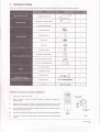
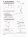
ATTACHED FITTINGS
Please check whether the following fittings are of full scope. lf there are some spare fittings , please restore them carefully.
1
1. lnstallation paper board
2. Soundproof/ insulation sheath
2
3. Connecting pipe group
1
4. Out-let pipe sheath
1
5.
o
Outlet pipe clasp
H
6. Drain joint
@
7. Seal ring
@
1
8. Remote controller
g
1
ffi
€w
9. Remote controller holder
1
0 Mounting screw(ST2.9x
11 .
1
0-C-H)
1
2
Alkaline dry batteries (AM4)
1
2
12. Owner's manual
1
3. lnstallation manual
1
14. Expansible hook
4
15. lnstallation hook
4
16 .Orifice
Btnnr-rmffi
1
Cautions on remote controller installation:
r
Never throw or beat the controller.
I
Before installation, operate the remote controller to determine its location in a
reception range.
Keep the remote controller at least 1m apart from the nearest TV set or stereo
equipment. (it is necessary to prevent image disturbances orroise interferences.)
Do not install the remote controller in a place exposed to direct sunlight or close (o a
heating source, such as a stove.
I
Note that the positive and negative poles are right positions when loading bafteries.
I
This manual is subject to changes due to technological improv€ment without further
Mounting screw B
ST2.9x1o-C-H
W
Remote controller
holder
Fig.3-1
notices.
installation manual
3
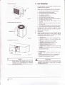
4.
INSPECTING AND HANDLING THE UNIT
At delivery, the package should be checked and any damage should
bdreported immediately to the service agent.
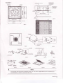
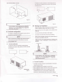
5.3 lnstallthe main body
r
1
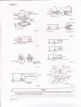
When handling the unit, take into account the following:
fl I
The existing ceiling (to be horizontal)
FraOile, handle the unit with care.
F]
^""0
damage.
'
Choose on before hand the path along which the unit is to be
brought in.
Move this unit as originally package as possible.
4
When lifting the unit , always use protectors to prevent belt
damage and pay aftention to the position of the unit's centre
The center of the hole should be at the same position of
that of the air conditioner body.
the unit upright in order to avoid compressor
3
Cut a quadrangular hole of 880x880mm in the ceiling
according to the shape of the installation paper board.
(Referto Fig.5-2)
'
Determine the lengths and outlets of the connecting pipe,
drainpipe and cables.
'
To balance the ceiling and to avoid vibration, please
enforce the ceiling when necessary.
2
Select the position of installation hooks according to the
hook holes on the installation board.
'
Drill four holes of g12mm, 45-50mm deep at the selected
positions on the ceiling. Then embed the expansible
of gravity.
hooks (fiftings).
.
Face the concave side of the installation hooks toward the
. expansible hooks. Determine the length of the installation
hooks from the height of ceiling, then .cut off the
5.
unnecessary part.
INDOOR UNIT INSTALLATION
5.1 lnstallation
. lf the ceiling
is extremely high, please determine
the
length of the installation hook according to facts.
place
3
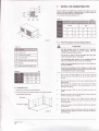
Adjust the hexangular nuts on the four installation hooks
(Refer to Fig.5-1,Fig.5-2,Fig.5-3 and Table 5-1 for specification.)
evenly, to ensure the balance of the body.
The indoor unit should be installed in a location that meets
the following reauirements:
'
lf the drainpipe is awry leakage will be caused by the
malfunction of the water-level switch.
'
Adjust the position to ensure the gaps between the body
and the four sides of ceiling are.even. The body's lower
'part should sink into the ceiling tor 10-12 mm (Refer to
Fig.&6).
There is enough room for installation and maintenance.
'
'
The ceiling is horizontal, and its structure can endure the
weight of the indoor unit.
.
The outlet and the inlet are not impeded, and the
'
influence of external air is the least.
.
.
.
.
The air flow can reach throughout the room.
Locate the air conditioner firmly by wrenching the nuts
after having adjusted the body's position well.(Refer to
Fig.5-7)
The connecting pipe and drainpipe could be extracted out
easily.
ln general, L is half of the screw length of the installation
hook. (Refer to Fig. 5-6)
I
New built houses and ceilings
There is no direct radiation from heaters.
1
CAUTION
Keep indoor unit, outdoor unit, power supply wiring and
transmission wiring at least 1 meter away from televisions
and radios. This is to prevent image interference and
noise in those electrical appliances. (Noise may be
.
2
generated depending on the conditions under which the
electric wave is generated, even if 1 meter is kept.)
ln the case of new built house, the hook can be embedded
in advance (refer to 2 mentioned above). But it should be
strong enough to bear the indoor unit and will not become
loose because ofconcrete shrinking.
After installing the body, please fasten the installation paper
board onto the air conditioner with bolts(M6X12) to
determine in advance the sizes and positions of the hole
opening on ceiling.(Refer to Fig. &8)
'
Please first guarantee the flatness and horizontal of
ceiling when installing it.
5.2 lnstallation procedures for fresh air
intake duct connection
I
Preparing the connection hole
'
Refer to 1 mentioned above for others.
Refer to 3 above
4
Remove the installation paper board.
Cut off the knockout hole on the side plate with a nipper.
Cut the inner insulation of the hole portion with a cutter.
(Referto Fig.5-4)
Placing the insulation
Put the insulation tightly around the hole of the unit as
shown.
The ends of the side plate and the inner insulation must be
completely adhered without leaving any clearance along the
circumference of the hole.
Make sure the inner surface of insulation tightly contacts the
inner insulation edge and the side plale. (Refer to Fig.*s)
--------installation manual
4
for installation.
3
CAUTION
After installing the body, the four bolts(M6x{2)must be
fastened to the air conditioner onto ensure the body is
grounded well.
Table 5-1
230 o12.7 a6"3! >260|ffiittffi
Fig.5-1
Fig.5-5
230
a15.9 a9.5
>26(
300
215.9 a9.5
)300lRfi0rcmlq
300
v19.1
300
a15.9 a9.5 >330
300
s19.1 a12.i
>33(
230 v12.7 s6.3a
>26(
rphlnd
>260
i?9iq
ro*{ I ilc{i
212.7 >30( fi0rcdql
230
t15.9 s9.5
300
z,19.1
a9.5 >300
300
v'19.'l
a9.5 >330
Fig.5-6
Fig.5-10
il10Ahohs
todrig
I
I
dlm
fhd
{R!
Cohd
Fis.5-7
Fig.611
All the pictures in this manual are for explanation purpose only. They may be slightly different from the air conditioner you
purchased(depend on model).The actual shape shall prevail.
installation manual
5
FIGURES 2
outlet foam
Fig.5-13
Fig.5-12
Gap not allowed
Fig.5-15
Leakage
Lean ove|l /50
""*-\
Fig.5-14
lnstallation cover's rope
Tap Screw
CC
Slide the four slidec
in lhe eresponding
channel when installing
the cover
Fig.*17
Fig.5-16
Lean ovet 1/50
(the fittings)
Fig.*19
Fis.5:1a
g
NOTE
from the air conditioner you
All the pictures in this manual are for explanation purpose only. They may be slightly different
purchased(depend on model).The actual shape shall prevail'
installation manual
6
5.4 lnstallThe Panel
Adjust the four panel hook screws
to keep the panel
horizontal, and screw them up to the ceiling evenly. ( Refer fo
Fig.+12.3)
CAUTION
Regulate the panel in the direction of the arrow in Fig.5-12.4
slightly to fit the panel's center to the center of the ceiling's
opening. Guarantee that hooks of four corners are fixed well.
Never put the panel face down on floor or against the
wall, or on bulgy objects.
Keep fastening the screws under the panel hooks, until the
thickness of the sponge between the body and the panel's
outlet has been reduced to about 4-6mm. The edge of the
panel should contact with the ceiling well. (Refer to Fig.S-l3)
Never crash or strike it.
1
I
Remove the air-in grill.
.
I
3
I
in
Fig.S-14 can be caused by
.
lf the gap between the panel and ceiling still exists after
fastening the screws, the height of the indoor unit should
be modified again. ( Refer to Fig.5-11-left)
'
You can modify the height of the indoor unit through the
openings on the panel's four corners, if the lift of the
indoor unit and the drainpipe is not influenced (Refer to
Fig.5-16-right).
Draw the grill up to an angle of about 451 and remove it.
(Referto Fig.5-10)
2
Malfunction described
inappropriate tightness the screw.
Slide two grill switches toward the middle at the same time,
and then pull them up. (Referto Fig.5-9)
Remove the installation covers at the four corners
Wrench off the bolts, loose the rope of the installation covers,
and remove them. (Referfo Fiy 5a1)
Hang the air-in grill to the panel, then connect the lead
terminator of the swing motor and that of the control box
lnstall the panel
with corresponding terminators on the body respectively.
Align the swing motor on the panel to the tubing joints of the
body properly. ( Referto Fig.sa)
Fix hooks of the panel at swing motor and its opposite sides
to the hooks of corresponding water receiver. ( Refer to
Fig.5-12.1) Then hang the other two panel hooks onto
corresponding hangers ofthe body. ( Referto Fig.5-12.2)
Relocate the air.in grill in the procedure of reversed order.
6
I
Relocate the installation cover.
Fasten the rope of installation cover on the bolt of the
installation cnver. (Refer to Fig.5-16-lett)
Press the installation cover into the panel slightly. (Refer to
Fig.5-16-nght)
CAUTION
Do not coil the wiring of the swing motor into the seal
sponge.
5.5 lnstall the distribution duct
Conditioned air can be distributes by means of a distribution duct.
Fresh air intake (O75)
Distribution duct
illil
Distribution duct
Distribution duct
Disrriburionducr
-
lllll
Fig.il20
installation manual
7
I
NOTE
model 18 to 24
model 30 to 48
Series A=350mm; Series B=85mm
series A=35llmm; series B=l55mm
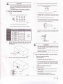
6.
OUTDOOR UNIT INSTALLATION
6.1
lnstallation Place
I
The outdoor unit should be lnstalled in the location that
meets the following requiements:
'
'
There is enough room for installation and maintenance'
'
'
lt must be a dry and well ventilating place'
The air outlet and the air inlet are not impeded, and can
not be reached bY strong wind.
The support is flat and horizontal and can stand the
weight of the outdoor unit. And will no additional noise or
vibration.
.
Your neighborhood will not feel uncomfortable with the
noise or exPelled air.
'
.
lt is easy to install the connecting pipes or cables'
.
There is no danger of fire due to leakage of inflammable
Determine the air outlet direction where the discharged
air is not blocked.
gas.
.
The piping length between the outdoor unit and the indoor
unit may not exceed the allowable piping length'
o
ln the case that the installation place is exposed to strong
wind such as a seaside, make sure the fan operating
properly by putting the unit lengthwise along the wall or
using a dust or shield.(Refer to Fig.6-1)
.
lf possible, do not install the unit where it is exposed to
direct sunlight.
.
lf necessary install a blind that does not interfere with the
'
During the heating mode, the water drained off the
outdoor unit ,The condensate should be well drained
air flow.
away by the drain hole to an appropriate place, so as not
to interfere other PeoPle.
ln case of one duct connection
18
The air volume in duct is around 300-360m3/h for model
'
Select the position where it will not be subject to snow
drifts, accumulation of leaves or other seasonal debris' lf
unavoidable, please cover it with a shelter'
'
Locate the outdoor unit as close
to 24 unit.
30
The air volume in duct is around 400-640m3/h for model
to 48 unit.
to the indoor unit as
possible.
possible, please remove the obstacles nearby to
prevent the performance from being impeded by too little
of air circulation.
' lf
The max. length of duct is 2m.
The original air outlet with the same direction of duct should
be sealed ln case of two duct connection'
'
ln case of two duct connection
The minimum distance between the outdoor unit and
obstacles described in the installation chart does not
mean that the same is applicable to the situation of an
airtight room. Leave open two
model
The air volume in one duct is around 200-260m3/h foi
1B to 24 unit.
of the
three
directions.(Refo re to Fig'G7, Fig'6-8' Fig'6-9)
@
The air volume in one duct is around 300-500m3/h for model
30 to 48 unit.
o
)
(o
The max. length of duct is 1.5m for one duct'
)o=.
The original air outlet with the same direction of duct should
be sealed.
Fis.6-1
I
NOTE
All the pictures in this manual are for explanation
purpose only. They may be slightly different from the ak
conditioner you purchased(depend on model)'The
actual shape shall Prevail.
installation manual
8
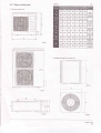
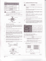
6.2
Figure of body size
Table 6-1
1. Split type outdoor unit
u2
n
560
335
360
312
324
695
R22
895
590
333
355
302
R407C
313
862
R41OA
(Fis.6-2)
990
624
366
396
340
354
966
852
582
368
390
328
340
660
BTYPE
R41OA
(Fis.6-2)
T1
990
624
366
396
340
354
966
:ondione
(Fig.6-2)
r- ]
T3
940
600
376
400
340
360
1245
(Fis.6-3)
R22
(Fis.6-2)
990
624
366
396
340
354
966
940
600
376
400
340
360
1245
R407C
900
590
378
400
330
340
1167
R41OA
lFio
6-31
B TYPE
R41OA
Fio.6-3i
2. Vertical discharge type outdoor unit
Fig.6-5
i*
installation manual
I
2. Vertical discharge type outdoor unit
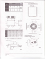
Table 6-2
(Wall or obstacle)
3. Centrifugal fan outdoor unit
Fis.6-9
(Wall or obstacle)
F
ltt
tLJ
lll
Table 6-3
^':"'
1174 1120 680
720
750
475
300
430
265
393
1328 702
740
770
520
336
500
296
443
1381 1328 702
740
770
520
336
500
296
443
338 783
820
850
568
398
574
342
463
138"1
Fig.6-10
3. Centrifugal fan outdoor unit
1394
6.3
1
a) ln case that suspending in the ceiling
Space of installation and maintenance
1. Split type outdoor unit
(Wall or obstacle)
Fig.6-11
installation manual
10
To
b)ln case that installing on the floor
dilge *
Fan u.rdd
rncrrbd
oudet b necessary to intercfiange pands too.
pdrd b attached
6
to fun stucture, which must be
fulotx.
Fig.612
I
Fig.6-14
NOTE
All the pictures in this manual are for explanation
purpose only. They may be slightly different from the air
conditioner you purchased(depend on model).The
actual shape shall prevail.
6.5 Moving and installation
Since the gravity center of the unit is not at its physical
'
center, so please be careful when lifting it with a sling.
Never hold the inlet of the outdoor unit to prevent it from
deforming.
6.4 Available configuration
Do not touch the fan with hands or other objects.
Four different configuration are available for oudoor unit only
Do not lean it more than 451 and do not lay it sidelong.
changing the panels and fan position.
Make concrete foundation accoding to the sepecif-ications of
the outdoor units.(Refer fo Fig.6-15)
NOTE
?
Keep in mind that fan unit weight is aprox 30kg ,the unit as
Fasten the feet of this unit with bolts firmly to prevent it from
collapsing in case of earthquake or strong wind.(Refer fo
Fig.6-15)
well as relevant equipment covered with the vinyl cover
during installation work.
Air inlet modification
To change air inlet is only necessary to interchange the
indicated panels position. Both panels use screws to be fixed
to unit chassis.
Fig.6-15
I
NOTE
All the pictures in this manual are for explanation
purpose only. They may be slightly different from the air
conditioner you purchased(depend on model).The
actual shape shall prevail.
r
'l .
Concrete Foundation
Foundation could be on flat and is recommended be 100-300mm
higher than ground level.
2.lnstall a drainage around foundation for smooth drain
3.When installing the outdoor unit fix the unit by anchor bolts of M10
Change Panel
Fig6-13
4.When installing the unit on a roof or a veranda, drain water
sometimes tums to ice on a cold morning. Therefore, avoid
draining in an area that people often use because it is slippery.
installation manual
11
7. INSTALL THE CONNECTING PIPE
Check whether the height drop between the indoor unit and
outdoor unit, the length of refrigerant pipe, and the number of
the bends meet the following requirements:
o
oI
(The number of the bends less than 15.)
Table 7-1
Fig.6-16
7.1
The Procedure of Connecting Pipes
CAUTION
Table 6-4
All field piping must be provided by a
licensed
refrigeration technician and must comply with the
relevant local and national codes.
Do not let air, dust, or other impurities fall in the pipe
system during the time of installation.
Drainage (Wide 1O0xDepth 150)
Mortar Hole (O10OxDepth 150)
The connecting pipe should not be installed until the
indoor and outdoor units have been fixed already.
Keep the connecting pipe dry and do not let moisture in
during installation.
Execute heat insulation work completely on both sides
of the gas piping and the liquid piping. Otherwise, this
Table 6-5
can sometimes result in water leakage.
Drill a hole in the wall (suitable just for the size of the wall
conduit), then set on the fittings such as the wall conduit and
its cover.
r
Suspended unit
1. Suspend the unit as the drawing indicates.
2. Ensure that ceiling can resist the Outdoor unit weight indicated
Bind the connecting pipe and the cables together tightly with
binding tapes.
Pass the bound connecting pipe through the wall conduct
from outside. Be careful of the pipe allocation to do on
damage to the tubing.
Connect the pipes. Refer to "How to Connect the pipes" for
details.
Expel the air with a vacuum pump. Refer to "How to expel the
air with a vacuum pump" for details.
Sling Bolt
open the stop values of the outdoor unit to make the
refrigerant pipe connecting the indoor unit with the outdoor
unit in fluent flow.
Suspension Bracket
Check the leakage. Check all the joints with the leak detector
or soap water.
Cover the joints of the connecting pipe with the soundproof /
insulating sheath (fittings), and bind it well with the tapes to
prevent leakage.
installation manual
12
Connect the indoor unit at first, then the outdoor unit.
CAUTION
'
Be sure to with insulating materials cover all the exposed
parts of the flare pipe joints and refrigerant pipe on the
liquid-side and the gas-side. Ensure that there is no gap
Bend the tubing in proper way. Do not harm to them.
Bend the pipe with thumb
between them.
lncomplete insulation may cause water condensation.
I
1
How to Connect the pipes
The bending angle should not exceed
Flaring
'
bendable pipe. The larger the bending radius the better it
o XXX
t?tn
to:)
ffi
I
.
.tTot
is.
Do not bend the pipe more than three times.
t.orun
mHm
I I I
901
Bending position is preferably in the middle of the
Cut a pipe with a prpe cufter. (Refer to Fig.7-1 )
ry
tl
Fig.7-4
When connecting the flare nut, coat the flare both inside
and outside with either oil or ester oil and initially tighten
by hand 3 or 4 turns before tighting firmly.
rig.z-t
.
lnsert a flare nut into a pipe and flare the pipe.
.
Refer to Table 4 for the dimension of flare nut spaces.
'\
Table 7-3
Fig.7-5
Be sure to use both a spanner and torque wrench
together when connecting or disconnecting pipes to /from
the unit.
25-26N.m
(255-265 kgf.cm)
45-47 N.m
(459-480 kgf.cm)
, rs\
I("-''
Remove the Cycle Service Panel and the Cover
Board, unscrewing the screws which secure it !o
the structure
Fig.7-6
A
CAUTION
Too large torque will harm the bellmouthing and too small
will cause leakage. Please determine the
torque
according to Table 7-2.
After the connecting work is finished, be sure to check
that there is no gas leak.
Cycle Sorvice Panel
How to expel the air with a vacuum pump
Cover
Fig.7-2
Remove the protection cover of stop valve
a
1.
Stop valve operation introduction
Openlng stop valve
1.
Remove the cap and tum the valve
the hexagon wrench.
counterclock-wise with
2.
Tun it until the shaft stops.Do not apply excessive force
to the stop valve. Doing so may breakthe valve body, as
the valve is not a backseat type. Always use the special
tool.
3.
2.
Make sure to tighten the cap securely.
Closing stop valve
1.
Remove the cap and turn the valve clochivise with the
hexagon wrench.
2.
Securely tighten the valve until the shaft contacts the
main bodyseal.
Make sure to tighten the cap securely.
For the tightening torque, refer to the table below.
installation manual
13
fab/'e74
7.2
Additional Refrigerant Charge
CAUTION
13.5-16.5
Refrigerant cannot be charged until field wiring has been
completed.
11.5-.' 13.9
Hexagonal
wrench 6 mm
Refrigerant may only be charged after performing the leak
test and the vacuum pumping.
a system, care shall be taken that its
maximum permissible charge is never exceeded, in view of
the danger of liquid hammer.
When charging
CAUTION
Always use a charge hose for service port connection.
Charging with an unsuitable substance may cause
explosions and accidents, so always ensure that the
After tightening the cap, check that no refrigerant leaks
arepresent.
appropriate refrigerant is charged.
seruice port
Refrigerant containers shall be opened slowly.
maintenance nul
Always use protective gloves and protect your eyes when
charging refrigerant.
r
seal
shafr hexagon
hole
Fig.7-7
The outdoor unit is factory charged with refrigerant. Calculate
the added refrigerant according to the diameter and the
length of the liquid side pipe of the outdoor uniVindoor unit
connection.(suitable for throftle outdoor unit)
Using the vacuum pump
Table 7-5
Loosen and remove the maintenance nuts of stop valves A
and B, and connect the charge hose of the manifold valve to
the service port of stop valve A. (Be sure that stop valves A
and B are both closed)
Connect the joint of the charge hose with the vacuum pump.
Open the Lo-lever of the manifold value completely.
Turn on the vacuum pump. At the beginning of pumping,
loosen the maintenance nut of stop valve B a little to check
whether the air comes in (the sound of the pump changes,
and the indicator of compound meter turns below zero). Then
fasten the maintenace nut.
When the pumping has finished, close the Lo-lever of the
manifold valve completely and turn off the vacuum
pump.Make pumping for 15 minutes or more and check that
the compound meter indicates -76cmHg(-1Xl05Pa)
Loosen and remove the cap of stop valves A and B to open
stop valve A and B completely, then fasten the cap.
Disassemble the charge hose from the service port of stop
valve A, and fasten the nut.
R(g): Additional refrigetant to be charged
L(m): The length of the refrigerant pipe(one-way)
D(mm): Liquid Side Piping Diameter
a'^i
NOTE
Y
lf a negative result is gotten for R from Table 7-4, no
refrigerant needs to be added nor removed.
Additional refrigerant will be twice of R from Table 7-4 if
the indoor unit installed throttle assembly.
Outdoor unit is equiped with a drain piping. lts position is
Outdoor
u1L
'
Gassrd
4 -:---l--gn
shown figure below
unit
ffi-y'B
Stop valve
Fig.7-8
Multi-meter
I
Pressure meter
-76 cmHg
Lo-lever
Hi-lever
Charge hose
Charge hose
* /
m,f
tr,
LGlever
installation manual
14
ffi
ffi
-l
A
B
Vacuum pump
Drain Piping
Fig.7-9
Fig.7-10
TableT-6
lf the outlet of the drainpipe is higher than the body's pump
joint, the pipe should be arranged as vertically as possible.
And the lift distance must be less than 200mm, otherwise the
water will overflow when the air conditioner stops. (Refer fo
Fig.5-18 in the figure page)
The end of the drainpipe should be over 50mm higher than
the ground or the bottom of the drainage chute, and do not
immerse it in water. lf you discharge the water direcily into
sewage, be sure to make a U-form aquaseal by bending the
Prepare a polyviny chloride with 21mm inner diameter
pipe up to prevent the smelly gas entering the house through
the drain pipe.
Fasten the tube to the drain hose with an adhesive and the
field-supplied clamp. The drain piping must be performed with
a DOWN-SLOPE pitch of 1125to 11100
Drainage test
'
.
Connect a siphon, as shown in figure below
Check whether the drainpipe is unhindered.
New built house should have this test done before paving
the ceiling.
Remove the test cover, and stow water of about 2000m1 to the
water receiver through the stow tube. ( Refer to Fig.E_l9 in the
figure page)
Slope 2 %
Turn on the power, and operate the air conditioner under the
'COOLING' mode. Listen to the sound of the drain pump.
Check whether the water is discharger well (a lag of lmin is
allowed before discharging, according to the length of the drain
pipe), and check whether water leaks from the joints.
Fig.7-11
Stop the air conditioner, turn off the powel and reset the test
cover to its original position.
I
NOTE
The drain plug is used to empty the water-receiver for
maintenance of the air conditioner. please stuff it
imposition at all times during operation to avoid leakage.
8.
CONNECT THE DRAIN PIPE
r
Fit the seal into the drain joint, then insert the drain joint into the
base pan hole of outdoor, rotate g0" to securely assemble them.
lnstall the drainpipe of the indoor unit
' You can use a polyethylene tube as the drainpipe
Fit the seal into the drain joint, then insert the drain.joint into the
base pan hole of outdoor, rotate 90. to securely assemble them.
Connect the drain joint with an extension drain hose (Locally
purchased), in case of the condensate draining off the outdoor
unit during the heating mode.
(ouldia.37-39mm, in-dia.32mm). lt could be bought at local
market or from your dealer.
.
lnstall the drain joint of the outdoor unit
Set the mouth of the drainpipe onto the root of the body's
pump-pipe, and clip the drainpipe and the out-let pipe sheath
(fittings) together firmly with the ouUet pipe clasp (fitting).
The body's pump pipe and the drainpipe (especially the
indoor part) should be covered evenly with the out-let pipe
sheath (fittings) and be bound tightly with the constrictor to
prevent condensation caused by entered air.
To prevent water from flowing backwards into the
air
conditioner while the air conditioner stops, please lean the
drainpipe down toward outdoor (ouflet-side) at a degree of
over 1/ 50. And please avoid any bulge or water deposit. (
Refer to Fig.5-17.a in the figure page)
I"',
@
Do not drag the drainpipe violenfly when connecting.to
the body from being pulled. Meanwhile, one
supportpoint should be set every 1-1.5m to prevent the
prevent
drainpipe from yielding (Refer to Fig.5-17a in the figure pagg).
Or you can tie the drainpipe with the connecting pipe to fix
it.(Refer to Fig.5-17.c in the figure page)
ln the case of prolonged drainpipe, you had better tighten its
indoor part with a protection tube to prevent it from loosing.
I
NOTE
All the pictures in this manual are for
explanalion
purpose only. They may be slightly different from the air
conditioner you purchased(depend on model).The
actual shape shall prevail.
installation manual
15
9. INSTALLATION
lnstallation Type 2
The hole is oppose to refrigerant pipe
OF FLANGE AND DUCT
Fresh air is intaken by indoor fan motors or ductable fan motor
devices on field. The posltions of fresh air intake can be
changed according to the installation of ductable fan motor.
No insulation matedal inside,
only removal board
Fig.9-1
I
NOTE
1. The device can be installed in ceiling cassette type
indoor units (severaldirection flow).
2. When installing the device, duct is needed on field
and the rated diameter is 75mm.
m"'-."
2
Fig.9-3
Stick insulation material 4 al indoor hole
3. The max. length of fresh air duct is 3m.
When metal duct pass through wooden wall, electric
insulation must be add between duct and wall.
The duct must be pulled out downside to prevent rain
and water entering.
Net cover must be set at places where duct explodes
to outdoor air to prevent birds and animals entering.
For different type of indoor units, the
installation methods are different and the
position of holes are different.
Removal the hole on the board.
lnstallation Type 1
The hole is oppose to drainage pipe
Fig.9-4
'
'
lnstallation Type
1
Pul the insulttion mtedal 4 m th€ inlerfae
of lhe hole as shom in F&t 99, tha stick
on the insid€ and surfa€ of the board. The
interfa@ of the hd€ €n rpl hae g€p-
]lo '
Abqrtl&nml---] WZm'
lnsulation Mal€rial
|l
Fig"9-5
lnstallation Type 1
Stick insulation material at the opening part
..-'-T.i---,/
ll
of the
board.
Berd
IF
)1"
oV)JI'-
tl.f-l
1t
7
/
Fig.9-2
installation manual
16
lnsulation Material
Fig.9-6
Ensure the interface of insulation material 4 closely contacts
with the inside insulation material and the board.
10.
Use screw 2 (M4X12,4 Pieces) to install flange at the hole, and
then stick insulation material 3.
Flange 1
wtRtNc
The appliance shall be installed in accordance with
national wiring regulations,
The air conditioner should use separate power supply
with rated voltage.
The external power supply to the air conditioner should
have ground wiring, which is linked to the ground wiring
of the indoor and outdoor unit.
The wiring work should be done by qualified persons
according to circuit drawing.
.
An all-pole disconnection device which has at least 3mm
sepaaration distance in all pole and a residual current
device (RCD) with the rating of above 10mA shall be
incorporated in the fixed wiring according to the national
rule,
Be sure to locate the power wiring and the signal wring
well to avoid cross-disturbance,
(M4x12,4 pieces)
Do not turn on the power until you have checked
carefully after wiring.
The power cord type designation is HO7RN-F.
I
NOTE
Remark per EMC Directive 2OO4fiOB,EC
For to prevent flicker impressions during the start of the
compressor (technical process), following installation
lnStall DUCt (the rated diameter:@75)
1 Connect the duct to the flange.(the flange is assembled with the
2
conditions do apply.
interface of duct.)
After connection, use the ethylene tape (provided on field) to
wrap the joint to prevent air-leakage.
1
The power connection for the air conditioner has to be
done at the main power distribution. The dishibution has
to be of a
low . impedance, normally
impedance reachei at a 32 A fusing point.
Wrap the joint to prevent airJeakage
2
the
required
No other eqiripment has to be connected with this power
line.
For detailed installation acceptance please refer to your
power supplier, if restrictions do apply for products like
washing machines, air conditioners or electrical ovens.
Fig.9-9
I
For power details of the air conditioner refer to the rating
plate of the product.
NOTE
g
1
All ducts must be completely heat-insulated.
2
The following phenomenon are not allowed when
installing duct:
vlx
A) Bend too much
U
Wrong
M
For any question contact your local dealer.
{0.1 Connect the cable
I
Dissemble the bolts from the cover.(lf there isn't a cover on
the outdoor unit, disassemble the bolts from the maintenance
board, and pull it in the direction of the anow to remove the
protection board.)
(Refer to Fig. 1 0-1, Fig. 1 O-2)
I
of indoor and outdoor units.
B)Too many bender
Wrong
Connect the connective cables to the terminils as identified
with their respective mached numbers on the terminal block
I
Re-install the cover or the protection board.
10.2 The Specification of power
(Refer to Tablel0-1-Tabte 10-5)
C) diameter reduce
\,2
f=<-r
v\
10.3 Wiring figure
(Refer to Fig. 1 0-3- F ig.
1
0-1 4)
Wrong
installation manual
17
11. TEST OPERATION
1. Split type outdoor unit
The test operation must be carried out after the entire
installation has been completed.
Please confirm the following points before the test operation:
The indoor unit and outdoor unit are installed properly.
a
a
Tubing and wiring are correctly completed.
a
The refrigerant pipe system is leakage-checked.
The drainage is unimpeded.
Fig.10-1
a
The heating insulation works well.
a
.
The $round wiring is connected correctly.
The length of the tubing and the added stow capacity of
the refrigerant have been recorded.
.
The power voltage fits the rated voltage of the air
conditioner.
2. Vertical discharge type outdoor unit
.
'
.
There is no obstacle at the outlet and inlet of the outdoor
and indoor units.
The gas-side and liquid-side stop valves are both opened.
The air conditioner is pre-heated by turning on the power.
According to the user's requirement, install the remote
controller frame where the remote controller's signal can
reach the indoor unit smoothly
3
4
Test operation
I
Set the air conditioner under the mode of "COOLING" with the
remote controller, and check the following points. lf there is
any .malfunction, please resolve it according to the chapter
"Troubleshooting" in the "Owner's Manual".
'
Fig.10-2
1) The indoor unit
a. Whether the switch on the remote controller works well.
b. Whether the buttons on the remote controller works
well.
c. Whether the air flow louver moves normally.
d. Whether the room temperature is adjusted well.
e. Whether the indicator lights normally.
f. Whether the temporary buttons works well.
g. Whether the drainage is normal.
3. Centrifugal fan outdoor unit
h. Whether there is vibration or abnormal noise during
operation.
l. Whether the air conditioner heats well in the case of the
HEATING/COOLING type.
'
2) The outdoor unit
a. Whether there is vibration or abnormal noise during
operation.
b. Whether the generated wind, noise, or condensed of by
the air conditioner have influenced your neighborhood.
c. Whether any of the refrigerant is leaked.
I
NOTE
e
All the pictures in this manual are for
explanation
purpose only. They may be slightly different from the air
conditioner you purchased(depend on model).The
actual shape shall prevail.
installation manual
18
CAUTION
A protection feature prevents the air conditioner from being
activated for approximately 3 minutes when it is restar:ted
immediately after shut off.
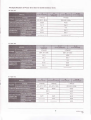
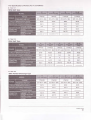
The Specification of Power (For Side Air Outlet Outdoor Unit)
r
Table 10.1
r
Table 10-3
'I
I
s
installation manual
19
I
Tablel04
r
Table
106
1-PHASE
1-PHASE
1-PHASE
3.PHASE
220-230V-60H2
220-230V-60H2
220-230Y-60H2
380V 3N-60H2
30/25
40125
40125
30n5
3x2.5
3x2.5
3x4.0
5x2.5
2.5
2.5
4.0
2.5
3x2.5
3x4.0
5x2.5
2x1.0
2x1.0
1x2.5
4x2.5
2-core shield wire 2x0.5
installation manual
20
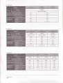
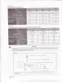
The Specification of Power (For Tr Gondition)
I
r
Tab*e 10-7
50Hz Spilt Type
r
l.PHASE
3-PHASE
1-PHASE
1-PHASE
220-240V-lfrHz
220-240V-fiHz
20t16
40n5
6080
40/30
3x2.5
3x2.5
3x4.0
5x2.5
2.5
2.5
4,0
2.5
3x2.5
3x4.0
5x2.5
5x2.5
4x0.75
3x0.75
4x0.75
1-core shield wire 1x0.5
1-core shield wire 1 x0.5
220-240V-
380V 3N-50H2
50112
Table 10-8
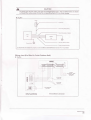
60Hz Spilt Type
l.PHASE
1-PHASE
208-80V-
60Hz
208-23 0V-
1-PHASE
208-A0V-SFlz
208-A0V-
3-PHASE
60Hz 208-fr0\/
3N-ffih
20t16
40t25
50/30
60/45
4025
3x2.5
3x2.5
3x4
3x6
5x2.5
2.5
2.5
4
b
2.5
3x2.5
3x4
3x6
5x2.5
4x0.75
3x0.75
4x0.75
4x0.75
5x2.5
1-core shield wire
I
601'12
l.PHASE
1
x0.l
-core shield wire 1 x0.
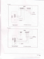
Table'10-9
50Hz Vertical Discharge Type
l.PHASE
1-PHASE
1-PMSE
3-PHASE
220-240V-ffiHz
220-240V-ffiHz
220-240V-fiHz
380V 3N-50H2
20!16
40t25
60/30
40125
3x1.0
3x1.0
3x1.0
5x1.0
3x2.5
3x2.5
3x4.0
5x2.5
4x0.7.5
4x0.75
4x0.75
4x0.75
installation manual
21
r
Table 10-10
60Hz Vertical Discharge IYPe
208-A0V-
r
1-PHASE
1-PHASE
1-PHASE
601'12
208-A0V-
60Hz
1.PMSE
3.PHASE
208-230V- 60Hz 208-230V- 60Hz 208-80V 3N-mHz
20116
40125
50/30
60/45
40n5
3x1.0
3x1.0
3x1.0
3x1.0
5x1.0
3x2.5
3x2.5
3x4
3x6
5x2.5
4x0.75
4x0.75
4x0.75
4x0.75
4x0.75
Table 10-11
The specification of Power (For centrifugal Fan Outdoor unit)
CAUTION
ffiganairgapcontactseparationinallactiVeconductorsshouldbeincorporatedinthefixedwiring
it must be replaced by the manufacturer or its service
wililp{,i"ii"n
according to the National
agent or-a similarly qualified person
r
itgrdg
r tn" rrppty cord is damaged,
to avoid a hatad
Fig.104
Power linking wiring (indoor)
Power linking (indoor and outd@r) wiring
Weak elecsignal wiring
Sirong elec-signal wiring
.
installation manual
22
performance
please ground the air conditioner well. otherwise, an important grounding may affect anti-jamming
of whole unit.
A
CAUTION
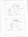
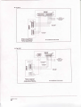
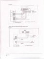
The wiring chart of both cooling only type and cooling& heating type in R22 and R410A series are shown
as follows,When wiring, please choose the corresponding figure,or it may cause damage.
r
Fig.10.5
Weak elec-signal link wiring
Strong elec-signal ink wiring
o
Ground the air conditioner propedy in case to affect its anti-interference function.For T3 Condition
Wiring chart (For Side Air Outlet Outdoor Unit)
r
Fig.10-6
POWER:
22O-240VAC- 50Hz
(3sre cable
3x2.smm' )
2sre €ble
-e
-
2x1.0 mm'
6
o
$core cable
3x2.5 mm-
lsre
sheild wire
:l'0.5 mm'
MODEL 18 (1 PHASE,5oHZ)
(For R22, Heating & Cooling)
Air Conditioner Link.circuit
installation manual
23
-!
I
F
{
{
MoDEL 18 (1 PHASE'soHz)
(For R22 , Cooling onry'
,.#fi"fl,ruh|,l1ffi'm;'d+",
installation manual
24
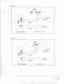
r
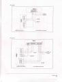
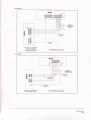
Fig.10-9
POWER:
220V-
6OHz
3-@re Cable
RW300/500 3x2.5 mm'
I
i
MODEL 18 (1 PHASEqtb)
(For M2, Co&Bq*y)
r
Air.Conditioner Link-circuit
Fis.10-10
POWER:
220-240V- SOHZ
OR 208-230V-60H2
MODEL 18 Tdl PHASE,50i60HZ)
(For R22, Heating & Cooting)
i
Air Conditioner Link.circuit
installation manual
25
3'core @ble
3x2 5 mm'
d
o
o
a
F
=
-3 ;-6v=
,r*-!|"',flif ,tTS3*t;3'Id"""'r
inslallation manual
26
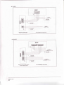
r
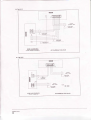
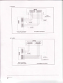
Fig.l0-13
POWER:
?2O-24OV- SOHZ
($@re €ble
'3x2.smm')
:=
I
a
e
r---!9
6l
F=l
e]-
=
MODEL24 (1 P|-|ASE,50HZ)
(For R22 and R410A C@ling mly)
Air Conditioner Link+ircuit
Fig.10-14
POWER:
38(M15V 3N- 50Hz
(s.@re cable
'5x
l.smm?)
MODEL 24 (3 PHASE,50Hz)
(For R22 and R4'10A, C@ling only)
Air Conditioner Link.circuit
installatim manual
27
I
r
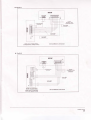
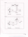
FIg.10-15
POWER:
20&230V- 60Hz
3-core Cable
3x2.5 mm"
MODEL 24 (1 PHASE,60HZ)
(For R22 . Hbatins & cooling)
(Foi n22 , xeating dcooling&PTc)
r
Fig.10-16
MoDEL 24^'48 (1 PHASE'60H2)
(For R22 , Cooling only)
installation manual
28
Air Conditioner Link.circuit
Air Conditioner Link-clrcuit
Fig.10-17
POWER:
22O-24OV- SOHZ
OR 208-230V-60H2
3-core Cable
3x2.5 mm'
MODEL 24 Tr (1 PHASE,50/60H2)
(For R22 and R41ilA, Heating & C@ling)
Air Conditioner Link-circuit
Fig.10-18
POWER:
22O-24OVAC- SOHZ
(3-core €ble
3x4.omm' )
MODEL 36 (1 PHASE,SoHz)
(For R22 , Heating & Cmling)
MODEL 30-36 (1 PHASE,50Hz)
(For R410A, Heating & Cooling)
Air Conditioner Link-circuit
insiallation manual
29
r
Fig.t0-19
POWER:
380-415V 3N- 50Hz
(s{ore €ble
5x2.5mm')
MODEL 30-48 (3 PHASE,S0HZ)
(For R410A, Heating & C@ling)
MODEL 36-48 (3 PHASE,5oHZ)
(For R22, Heating & Cooling)
Air Gonditioner Link-circuit
Fig.10-20
rffii
I tooot
n3bqqdd
nl
\l
I
\E
POWER:
\
220-24oV- SoHz
(3-@€ mble
4
=L€r)
-l
=
=
a
r----r
EFE
sheild wire
1x0.5 mm'?
I
1-@B cable
'1x2.5 mm'
liil:ls-
l-ril=ld-
hn.ld-
3@re €ble
3x4.0 mm'
=.-=
le o1=
la el-=
-q
le el-
--T
MODEL 36 (1 PHASE'sOHZ)
(For R22 ; Cooling only)
MODEL 30-36 (1 PHASE,SoHZ)
(For R22 and R4l0A, C@ling only)
insiallation manual
30
' 3x4.Omm')
1€re
I
Air Conditioner Link-circuit
Fig.10-21
POWER:
380V 3N- 50Hz
(s€re €ble
'5x2.5mm'?
)
'l-€re €ble
1xl.O mm'?
MoDEL 36-48 (3 PHASE,SoHZ)
(For R22 , C@ling mly)
Air Conditioner Link+ircuit
MODEL 30-,18 (3 PHASE,SoHZ)
(For R4104, C@ling only)
.
Fas.10-22
POWER:
22G240V- 50Hz
OR 208-230V-60H2
I
i
!l
\
MODEL 36 T3 (1 PHASE,50/60H2)
(For M2, Heating & Cooling)
3s.e
cable
lg'q'
Air Gonditioner Link.circuit
installation manual
31
r
Fig.{0-23
ll
-t
\
\il
\
sffCabl€
5x2.5 mm'
4ffe
csble
4xo.z5mm'?
Air Conditioner Link-circuit
MODEL 36-48 (3 PHASE,50/60H2)
(For R22, Heating & Cooling)
ilOMRUillI
lEl?-='=FFA=l
n,ffi.n,
lo--l
tri-l9l
P,i[H-
=trtr
a
&.tnil
6
F
el0[l
l!Dl6{q<
Iel=lok-
6'@lol.ltEk
16il*ld<
li---ll
MOOEL 42 (3 PHASE,ooHZ)
(For R22 , Heating & Cooling)
(Foi R22, Heating &Cooling&PTc)
installation manual
32
Jl
POWER:
380V-3N 60Hz
tr
tl-
ls" oG Cable RW30O/
Air Conditioner Llnk-circuit
r
Fig.'|0-25
Fffil
l-l6ri5r6r6li5rd-l
nzl
ilmoRulllr
n,
=ffi
I
POWER:
380V-3N 60Hz
o
=l[01
I
Cable
ffi
MODEL 42 (3 PHASE,60HZ)
(For R22 , Cooling only)
r
.rll
l.
f s-.,
/
)able
H07RN 5x 2.5 mm':
Air Conditioner Link.circult
Fig.10-26
MODEL 48 (1 PHASE, 00Hz)
(For R22 , Heating & Cooling)
Air Gonditioner Link-circuit
installation manual
33
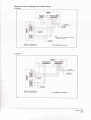
Fig.10-27
y&c lEl=l=lE=l=l=l=l=l=l-l Y&G
sr{e
-[mi
i I l6l^le1-1
I E:trF
4
llo
=
F h---T-l or
POWER:
380-415V
3N-
50Hz
(5-core cable
5X2.5m2 )
ol
(S-core cable
5X2.5 m2 )
s-core cable
gxz.s nm
6O00OBtu/h B tYPe(3-Phase)
(
-1
,1
For R410A,heating&cooling )
2
Air Condition Link-Circuit
Wiring chart (For Vertical Discharge Outdoor Unit)
T
{
Fig.10-28
{t
POWER:
220V-
*tE
OR 20&230V- 60Hz
3€re
Cable
3x 1.0 mm'
POWER:
220V- S0llz
oR 208-230V3-@re Cable
3x2.5mm'?
MODEL 24 T3 (1 PHASE, 50/60H2)
(For R22 , tieating & Cooling)
installation manual
34
Air Gonditioner Link.circuit
60Hz
Fis.10-29
3{re
Cable
3x1.0 mm'
POWER:
220Y-
SOHz
OR 208-230V- 60Hz
'I' 3sre cable
3x25mm'z
f
MODEL 18 Ts (1 PHASE,50/60H2)
(For R22 , Heating & Cooling)
Air Gonditioner Link.circuit
Fig.10-30
-l
POWER:
22OV- SOHZ
OR 208-230V- 60Hz
f
/
\
4sre
\
3rore cable
3x1.0 mm'2
cabte
lrsiqrr'
POWER:
22OV- 50Hz
OR 208-230V- 60Hz
'f'
/
l
MODEL 36 Ta (1 PHASE, 50/60H2)
(For R22 , Heating & Cooling)
3-core cable
3,4.omm'
Air Gonditioner Link-circuit
installation manual
35
r
Fi9.1031
POWER:
208-230V- 60Hz
3€re
Cable
3x1.0 mm'
\
4€E
cable
\ ----t:!z9r!4!-l
POWER:
208-230V- 60Hz
'f
/
' 3ore
cable
3x6.0mm'
Air Conditioner Link-cilcuit
MoDEL 48 Tr (1 PHASE, 60Hz)
(For R22 , Hebting & Cooling)
Fig.t032
POWER:
380V 3N- sOHz
oR 20&230V 3N- 60H
f s€re cable
/ s't.o mm'
4sre
Cable
410.75 mm'
.
.
POWER:
380V 3N- SOHZ
oR 208-230V 3N- 60Hz
MODEL 36-48 Ts (3 PHASE, 50/60H2)
(For R22 , Heating & C@ling)
inslallation manual
36
Air Conditioner Link-circuit
Wiring chart (For Centrifugal Fan Outdoor Unit)
r
Fig.10€3
ilMRUil]I
Y&G
POWER:
22O-24OVAC SoHz
(
t
NOTE:
R is shorting slub g@p what put lnlo
of C€nfitugd Fan Outd@r Unit.
MODEL 24-36 (1 PHASE,50Hz)
(For R410A,, Heating & C@ling)
r
elstri€l@nt ol box
Air Conditioner Link-circuii
Fig.10-34.
MODEL 30-48 (3 PHASE,SoHz)
(For R410A,, Heating & C@ling)
Alr Conditioner Link.circuit
instiallalion manual
37