1
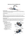
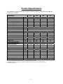
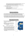
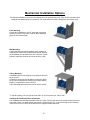
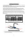
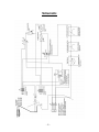
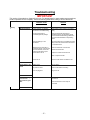
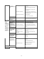
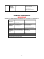
CellarMate
The Key to Wine Cellar Climate Control
Installation, Operation, and Maintenance Manual
Please read the following information, especially the safety information,
to ensure that you receive the maximum benefits of owning a CellarMate,
CUSTOMER WARRANTY REGISTRATION
Please complete and mail the Product Registration Card with a copy of your purchase receipt. By registering
your product, you will automatically be enrolled in our Consumer Protection Program and receive the
following:
Product Safety Notification
Registering your product allows us to contact you with updates and notifications about your CellarMate
model.
Confirmation of Ownership
We store model numbers, serial numbers, and owner information in our archives for ten years. In the event
of fire, flood, or theft, your registration serves as proof of your purchase for insurance purposes.
Warranty Service
Completing the Product Registration Card will expedite efficient warranty service.
Please cut on dotted line and mail registration form to: CellarMate LLC, PO Box 257, West Cornwall, CT 06796
------------------------------------------------------------------------------------------------------------------------------------------------
-2-
Table of Contents
OVERVIEW OF THE CELLARMATE UNIT............................................................................................................. 4
DIMENSIONS.................................................................................................................................................................. 5
PRODUCT SPECIFICATIONS..................................................................................................................................... 6
SAFETY CONSIDERATIONS ...................................................................................................................................... 7
PRE-INSTALLATION PROCEDURE ......................................................................................................................... 8
ELECTRICAL INSTALLATION: ................................................................................................................................ 9
THERMOSTAT CONNECTION: ................................................................................................................................. 9
MECHANICAL INSTALLATION OPTIONS ........................................................................................................... 10
INSTALLING THE DUCTWORK.............................................................................................................................. 11
START UP AND OPERATION ................................................................................................................................... 12
SCHEMATIC................................................................................................................................................................. 13
MAINTENANCE........................................................................................................................................................... 14
TROUBLESHOOTING ................................................................................................................................................ 15
ADVANCED TROUBLESHOOTING......................................................................................................................... 18
CELLARMATE WARRANTY .................................................................................................................................... 19
-3-
Overview of the CellarMate Unit
Evaporator Section
Cool air is supplied to the wine cellar through any of three outlets. Return air from the cellar enters the
evaporator coil section. A drain pan is located directly below the evaporator coil to capture condensate and
is fabricated from aluminum to prevent corrosion.
Condensing Section
Ambient air is circulated through the condenser section, and can be discharged through any of three outlets.
Cabinet
The cabinet and access doors are constructed of aluminum with a powder coated finish for corrosion
protection and an attractive, maintenance-free appearance. Unit is insulated to prevent condensation and
optimize efficiency. Removable access panels are provided to facilitate maintenance, duct connections, and
access to wiring components.
Electrical Controls
The electrical components and controls are located on a hinged access panel for easy accessibility. Wires
are numbered and color coded to match the wiring diagram. Electric power is supplied by a cord.
Thermostat controls are 24 volt, supplied from an internal transformer. The 230 volt units are capable of
operating at 208 or 240 volt by changing the leads on the control transformer. (See Wiring Diagram)
Refrigerant Circuit
The factory-charged circuit includes:
• A thermal expansion valve.
• A filter dryer.
• An automatic low pressure switch.
• An automatic high pressure switch.
• Two motorized impeller blowers,
with permanently lubricated direct
drive motors.
• A self-lubricated compressor with
internal overload protection.
Standard manufacturer’s warranty
is one year.
• Two heat exchanger coils.
• Environment-friendly refrigerant,
only R-134a.
-4-
Dimensions
Model Number
Dimensions - Nominal
A - Width
B - Height
C - Length
D – Condenser Discharge
Location
E - Evaporator Discharge
Location
F - Inlet Opening Width
G - Drain Opening Location
H - Discharge Opening Width
I - Inlet Opening Height
Weight
Refrigerant charge - 134a
25
50
88
200
Inches
Inches
Inches
14
14.5
36
22
14.5
40
22
14.5
40
22
18
43
Inches
23
25
25
26
Inches
Inches
Inches
Inches
Inches
5
10.63
19
8
11.28
5
10.63
21
10
11.28
5
10.63
21
10
11.28
5
18.88
24
11.63
15
Lbs.
Oz.
80
19
125
26
145
34
195
50
-5-
Product Specifications
The CellarMate is designed to operate at or above its rated capacities for total BTUH and CFM under
recommended conditions.
Model Number
Performance
Nominal Tonnage
Nominal Compressor
Net Cooling capacity*
@ 70 DEG F Ambient
@ 80 DEG F Ambient
@ 90 DEG F Ambient
Controls
Type
Accuracy
Evaporator Section
Fan motor Size
Rated air flow
Air flow with 25' flex duct
Condenser Section
Fan motor Size
Rated air flow
Air flow with 25' flex duct
Electrical Requirements
Power requirements
Current Draw - Cooling mode
minimum Circuit Size
Typical Testing Data (Factory)
Head pressure
Suction Pressure
Condenser Inlet Temperature
Condenser Outlet Temperature
Evaporator Inlet Temperature
Evaporator Outlet Temperature
Agency Approval
025
050
088
200
Ton
HP
1/4
1/3
1/2
1/2
1
1
2
2.5
BTUH
BTUH
BTUH
3300/3650
3000/3300
2800/3050
5600/6050
5300/5700
4850/5275
8400/9100
7800/8450
7300/7900
16200/17750
15200/16550
14100/15350
Room mounted non-programmable thermostat
± 2°F
Watts
CFM
CFM
75
235
207
100
430
400
195
510
485
240
740
715
Watts
CFM
CFM
75
253
220
100
400
365
195
500
475
240
750
720
V/P/H
Amps
Amps
115/1/60
8.6
15
115/1/60
11.9
15
230/1/60
9
15
230/1/60
16
20
psig
psig
Deg F
Deg F
Deg F
Deg F
159
40
81
98
56
44
140
140
30
25
74
79
98
99
55
57
44
43
ETL - Conforms to UL Std. 1995
138
27
78
107
55
46
*1. Net cooling capacity @ cellar temperature & humidity of 55°F & 60% RH / 60°F & 60% RH and at rated airflow. Reduce capacity by
3% for each 10% reduction in either condenser or evaporator airflow, 5% for both.
2. Cellarmate reserves the right to make changes to this document without prior notice at its sole discretion.
3. All ratings @ sea level.
-6-
Safety Considerations
When performing maintenance, always use the following Lockout/Tag-out Procedure.
More than one power source may be present. Disconnect all power sources.
Lockout/Tag-out Procedure
• Turn power switch to OFF.
• Lights should be off.
• Unplug unit from electrical outlet.
WARNING
•
•
•
•
•
•
•
•
•
•
•
•
•
•
•
•
•
Never reach into a unit while the fan is running.
Never open an access door downstream of the fan while the fan is running.
Do not expose the unit to rain or moisture.
Check weight specifications to confirm that supports are adequate.
Confirm that supports are designed to meet local codes and ordinances.
Do not remove access panels until fan impellers have completely stopped. Fan impellers continue to
turn (free-wheel) after the power is turned off.
Never pressurize equipment above the specified test pressure. (See Specification Sheet)
Do not operate near water.
Do not block any supply or return air register.
Do not modify or change polarized or grounding plugs. If the provided plug does not fit into the
outlet, consult an electrician for replacement of the obsolete outlet.
Only use attachments/accessories specified by the manufacturer.
The CellarMate units only operate on 120 VAC or 230 VAC, 1 phase 60Hz power source.
Always ground the outlet to provide adequate protection against voltage surges and static charge
build-up.
Refer all service to qualified personnel.
Do not place anything on top of the unit.
Do not use extension cords.
Use only dedicated power outlet boxes of the specified capacity.
-7-
Pre-installation Procedure
Pre-installation Test
Before installing your CellarMate unit, use the following procedures to test for non-visible shipping damage.
• Set the unit on the floor or on a sturdy level surface.
• Confirm that both blower impellers spin freely. Spin both blowers and observe any interference;
blowers are lubricated and should spin rapidly when spun.
• Plug the power cord into an outlet.
• Turn the main power switch to ON. The power indicator light should be on.
• Override the timer: The built-in timer prevents short cycling and keeps the unit from turning on right
away. Open the thermostat cover. Simultaneously press the fan and UP arrow buttons. The unit will
run as long as the temperature of the space is above the thermostat set point. After several minutes,
the unit will expel cold air from the evaporator section and hot air from the condenser section.
• Listen for unusual noise or vibration.
Pre-installation Procedure
Determine and review the following important information:
• Where the unit will be located; e.g. built into the wall or mounted remotely and ducted into the cellar.
o INDOOR USE ONLY! Unit should be installed in an area protected from the weather
and protected against any flooding. CellarMate units are not designed for outdoor
installation. If the unit must be installed outdoors, use a rain-proof enclosure and lowambient kit.
o Where the supply and return grills will be placed to achieve preferred temperature gradient
and circulation.
o If the condenser heat exhaust will be ducted away.
o Site must allow for access to all panels. 3 feet of clearance is required to allow room for
equipment in case the unit needs to be serviced. Additional clearance near the access panel
is desirable.
o The unit should be installed within 2 meters (~6 feet) of a standard 15 amp wall outlet (DO
NOT USE AN EXTENSION CORD).
o It is best if the unit can be installed where the shortest amount, if any, duct work is required.
It is recommended that no more than 25’ of duct should be used for any single input or
-8-
•
•
output from the system. Total duct work is recommended not to exceed 50’. If longer runs of
duct are required, secondary fans must be used to maintain CFM output.
o The condensate drain line needs to be considered when selecting an installation site.
o Unit should be level with the top side up during operation.
The unit is designed to operate with an ambient (air intake) temperature of 40 deg to 90 deg F.
All required parts are on-hand.
o The electrical plug and outlet have the correct configuration.
o Breakers are the proper size.
o The cellar has adequate insulation and vapor barrier.
o Ducts are the correct size.
o There is ample space around the unit to allow access for maintenance and repair.
Electrical Installation:
• The unit is designed so that it can be installed without opening the electrical access panel. If for any
reason the access panel needs to be opened it should be done only by qualified personnel.
• The unit main power (110VAC or 230VAC) branch circuit shall be fused at 15 to 20 amps.
• The unit has a delay timer that will not allow the compressor to start for a lock-out period after the power
has been disrupted. This time is adjustable but has been preset at the factory for 5 minutes.
• The unit is supplied with high and low pressure switches on the refrigerant line. These switches will not
allow the compressor to operate if the refrigerant charge is too low or too high. There is no manual
reset on either switch and normal operation should resume once the condition has been corrected.
Thermostat Connection:
• 24 VAC is on screw terminal 6 (red, R) of the screw
terminal block on the front panel.
• 24 VAC return or common is on screw terminal 5
(brown, B)
Note: The 24 VAC has circuit breaker protection.
• At a minimum the following control lines from the
thermostat are required:
o Cool (yellow, Y) on screw terminal 1
o Fan (green, G) on screw terminal 2
Notes:
• The unit has no internal support for humidity or heater
control. If a duct heater and or humidifier are coinstalled you may attach the thermostat humidifier
control line to screw terminal 3 (blue, B) and the duct
heater control line on screw terminal 4 (white, W).
• If a duct mounted heater and or humidifier are used
the humidifier must be downstream in the airflow
from the heater. Check local codes before installing
such equipment.
-9-
Mechanical Installation Options
The following installation instructions and diagrams are for general ideas only. They are not intended to be a
complete and detailed guide for installation. The Cellarmate 025 model is designed to fit between studs.
Floor Mounting
Elevate the CellarMate on a 2”x4” frame with a plywood
surface to protect it from water. This will allow adequate
space for the external drain.
Wall Mounting
Confirm that the load bearing capacity of the supports is
adequate and meets local codes and ordinances. Support
the CellarMate on both sides of the wall. Use floor or knee
braces to transfer the load of the unit to the floor or wall.
Ceiling Mounting
CellarMate units are not designed for suspension from the
top of the unit.
Construct a structurally sound platform on which to place
the unit when hanging from ceiling joists. Ensure that the
platform is supported on all four corners.
Leave adequate space above the unit for service access.
To operate properly, the unit must be level within ¼” end to end and 1/8” side to side.
Installing the Condensate Drain Connection
The CellarMate dehumidifies the inside of the wine cellar. The unit will remove the excess moisture from the
wine cellar. There is no water trap on the drain line internal to the unit. A commercial trap can be installed
external to the unit or a loop can be placed in the supplied flexible drain tube.
- 10 -
Installing the Ductwork
The following installation instructions and diagrams are for general ideas only. They are not intended to be a
complete and detailed guide for installation.
DO NOT EXCEED A TOTAL OF 25’ FOR EACH LENGTH OF DUCTWORK RUN, OR 50’ TOTAL. Place the
unit as close to the wine cellar as possible to reduce the length of the duct runs. Use straight, short ducting.
To prevent transmitting vibration and noise, add ¼” thick rubber pads.
Ambient air can be directly drawn into the condenser inlet, or can be ducted from an alternate location.
Condenser exhaust does not need to be ducted to a remote location unless installation location is not
desirable or capable of handling the exhaust heat. Condenser exhaust and evaporator output (cool air) can
be ducted from the unit from either of the two side openings or out the top opening of the unit.
Use ductwork to connect the unit to the supply and return outlets in the wine cellar. Use only insulated
ductwork. Installing the supply and return outlets too close together will create an undesirable circulation
loop. Appropriate spacing between the supply and return outlets will increase the efficiency of cooling your
cellar.
Ductwork can also be used on the condenser section to redirect the hot air exhaust and supply conditioned
air to the unit’s inlet.
Recommended insulated Flexible Ductwork Sizing Chart
Model #
25
50
88
200
Notes:
Condenser (heat rejection)
Coil
Evaporator (cooling) Coil
Supply Air
Supply Air
Return Air
Return Air
Single Double
Single Double
8"
8"
6"
8"
8"
6"
10"
10"
6"
10"
10"
6"
10"
10"
8"
10"
10"
8"
12"
12"
10"
12"
12"
10"
1. The above sizes are internal diameter in inches
2. if a single supply is used out of the unit, but then splits into two
ducts, use the sizes indicated for "Double" after the split
Duct work warnings and recommendations
•
•
Avoid crimping the flexible ducts, which will reduce air flow and cause erratic operation.
Be sure that all ducts and surfaces that are in contact with the air flow are insulated and have a
vapor barrier on the outside surface.
- 11 -
•
•
•
•
•
•
•
•
•
•
•
•
•
Support the flexible duct often to prevent sags or bends. (Place supports close enough to prevent
the flexible ducting from sagging or bending).
Stretch the duct to create a smooth interior and reduce air resistance. Rigid ductwork is best.
Insert a metal elbow in the flexible duct at 90° bends to maintain form.
Use straight and short lengths of ductwork.
Review the Air Flow Illustration on page 8 for duct connection options.
Remove the panels or grilles from the openings where the ductwork will be connected and save the
screws.
Install the panels with the duct collars using the screws from the original panels or grilles. Handle
the gaskets with care.
Pull the outer plastic wrapping and insulation away from the end of the duct to expose the reinforced
duct liner.
Connect the flexible duct by inserting the exposed portion into the duct collar.
Clamp the tie straps around the inside liner. Fasten the duct to the duct collar.
Do not clamp the tie straps around the outside insulation— over time, insulation will compress and
loosen.
Secure the duct collar panel to the unit using the screws set aside.
Non-insulated ducts and surfaces can cause exposed metal surfaces to sweat, further degradation
of the insulation, and a loss of equipment cooling capacity.
Start Up and Operation
•
•
•
•
•
Check all ductwork and electrical connections to confirm they are secure.
Replace all panels that were removed during installation.
Make sure that all openings on the evaporator side of the unit are covered with either a panel,
ductwork collar, or a grille. All openings on the condenser side do not need to be covered if it is to
exhaust to the ambient air, and/or if the hot air intake is coming from the ambient air.
Turn the rocker switch to ON. The switch will light up to indicate that the unit is receiving power. The
unit may not begin operating immediately due to the built-in timer.
Follow the included thermostat directions to setup.
Listen for the compressor. The hum will be audible, with no excessive vibration or sounds.
Initially, the unit may run continuously for several hours—up to a day or more—while it lowers the cellar
temperature. Once the unit reaches the set point temperature, it will begin to cycle as it continues to lower
the bottle temperature to the set point. The cellar air temperature will reach the set point before the bottle
temperature.
The fans will continue to free-wheel after the unit cycles off. The bottom of the compressor stays warm; even
when the unit is OFF.
- 12 -
Schematic
- 13 -
Maintenance
General Maintenance
WARNING
Before performing maintenance on the unit, read the safety information contained within the safety chapter
of the CellarMate Manual.
High voltages are present in the cabinets. Turn all power OFF. Use the Lockout/Tagout procedure before
opening panels.
Maintenance on CellarMate units requires working with high voltage and sheet metal with sharp edges. Only
qualified personnel should perform maintenance. Some tasks require knowledge of mechanical and
electrical procedures. Make sure you are familiar with all hazards, general safety-related procedures, and
safety labels on the unit.
The CellarMate is designed for minimum maintenance. The refrigerant is hermetically sealed and requires
no maintenance. The fans require no maintenance. Maintenance may be required if there is dust or dirt in
the air stream.
Annual
•
•
•
•
•
•
•
•
•
•
•
Check filter and drain trap - clean if needed.
Check for noise or vibration.
Check for short-cycling of the unit.
Replace filters if worn or plugged beyond cleaning.
Check evaporator and condenser coils for dirt. Use a vacuum with the brush attachment to clean the
coils.
Clean condensate pan under the evaporator coil by flushing. Keep the drain pan clear of debris.
Inspect the cabinet for corrosion or rust.
Inspect for dirt build-up on or inside the unit. Clean the unit by vacuuming or wiping it down.
Check for loose insulation, fasteners, gaskets, or connections.
Check the wiring connections and integrity of cords.
Examine ducts for any cracks or breach.
- 14 -
Troubleshooting
IMPORTANT
This section is intended as a diagnostic aid, only. For detailed repair or parts replacement procedures,
contact a qualified service company. Check the following table before calling a service technician.
PROBLEM
POSSIBLE CAUSE
SOUTION
Start Up
General Problems
Loose, improper, or defective
thermostat or humidistat wiring
Check power and thermostat or humidistat
wiring.
Incorrect thermostat or
humidistat (optional) settings
Check the thermostat and optional
humidistat setup for the application. Read
the thermostat troubleshooting guidelines in
the Thermostat Installation and Operating
Guide.
Changed settings on the
thermostat
The internal timer did not complete the timed
delay. Follow the manufacturer’s instructions
to override the timer.
Blockage of the evaporator or
condenser air flow. If the air flow
becomes blocked, the manual
reset high limit switch opens
and shuts the unit off.
Check for obstruction of the air flow
Remove the obstruction
Inspect the air filter for dirt and dust
Clean or replace the filter
Power Switch Light
is Off
Power Switch Light
is On and the
Thermostat Light is
OFF
Unit shuts off
Push the rocker switch to restart the unit
Switch not on
Turn on switch
No power to outlet
Check circuit breaker and wiring
Unit not plugged in
Plug in the unit
No power to thermostat
Check wiring for loose, broken, or frayed
connections.
Check transformer for 24v output to
thermostat
- 15 -
Power Switch Light
is On and the
Thermostat Light is
On
Thermostat is not setup properly
Check wiring for loose, broken, or frayed
connections.
Check thermostat setup in the included
guide.
Press fan ON switch to manually check
evaporator fan.
Compressor not operating
Wait several minutes. Compressor has a
timer installed on access panel to delay start
up (factory set: 5min).
Condenser air flow is blocked
Remove blockage
Clean filter and coil (if needed)
Temperature
Control
Issues:
Problems are
occurring even
though the unit
seems to be
fully
operationalevaporator fan
blows air into
the cellar and
compressor
and condenser
fans runs.
High Pressure
Switch Has Shut the
Unit Down
Head pressure in unit is too high
Remove any obstructions restricting air flow
through the coils or filters. Restart the unit.
Unit is Operating
and Blows
Evaporator Air, but
the Supply Air is
Not Colder Than the
Return Air from the
Cellar
Thermostat not set up properly
Check thermostat set up in the
manufacturer’s thermostat guide.
Compressor not operating
High pressure switch open, restart unit.
Condenser air flow is blocked
Remove blockage, clean filter and coil (if
needed)
Thermostat set too low on
cooling
Reset thermostat to higher cooling
temperature
Thermostat not controlling
temperature
Wiring integrity compromised (shorted),
replace wiring
Cellar Temperature
is Too Low (Below
51°) When Unit is
Not Running
Too much heat loss to adjacent
spaces
Increase insulation around the ductwork and
doorways
Cellar Temperature
is Too High, but
Supply Air is Cold
Not enough evaporator air flow
Cellar Temperature
is Too Low (Below
51°) When Unit is
Running
Add heater
Remove blockage in supply or return
ductwork
Check and clean filter and coil
Coil frozen—shut-off unit for two hours
Cellar loads are too high
Install additional insulation
Replace with larger unit
- 16 -
Cellar
Humidity
Humidity Too Low
or Supply Air is Too
Cold, Without
Optional Humidifier
Not enough evaporator air flow
Remove blockage in supply or return
ductwork
Check and clean filter and coil
Coil frozen—shut-off unit for two hours
Defective Thermal Expansion
Valve
If under warranty, call for service
If not under warranty, call a refrigeration
technician
No moisture being added to
cellar
Add CellarMate humidifier or a room
humidifier
Defective Thermal Expansion
Valve
If under warranty, call for service
If not under warranty, call a refrigeration
technician
Humidity Too High
When Unit is
Running, But Not
Cooling
Compressor
Clear blockage of condenser air flow
Humidity Too High
When Unit is Not
Running
Unit needs to run to dehumidify
See Unit Not Operating section of the
Troubleshooting section
Humidity Too High
When Unit is
Running and
Cooling
Too much evaporator air
Add some resistance to air flow. Install a
damper in the ductwork.
Unit Operates but
the Power Switch
Light is Not On
Bulb is burned out Replace bulb
Bulb is burned out Replace bulb
Unit is Leaking
Water
Trap plugged
Clean trap
Condensate pan plugged
Remove blockage and clean
Unit not level
Level with shims
Noise is from air flow
Redirect air flow
Humidity Too Low
Without Optional
Humidifier
Miscellaneous
Problems
Unit is Running
Properly, but the
Sound of Unit is
Objectionable
Ambient temperature above 95°F
Too much moisture in cellar
Poor vapor barrier installation
Add baffles
Add insulated ductwork
Noise is from unit
- 17 -
Add sound baffle between unit and occupied
space
High Pressure
Switch in the
Refrigeration
System Switch
Shuts off Unit
The head pressure is above 275
psi
Restricted air flow through the condenser
caused by an obstruction blocking the air
flow in the ductwork or grille
Dust covering the filter
Contact a refrigeration technician
Advanced Troubleshooting
IMPORTANT
This section is for qualified refrigeration service technicians, only. The technician should repeat the previous
troubleshooting steps before these more technical solutions.
PROBLEM
Obstructions and
Dirty Filters/Coils
Unit Cycles On and
Off More than 8
Times/Hour
POSSIBLE CAUSE
Condenser fan not operating
SOUTION
Repair or replace
Defective switch
Replace
Thermostat malfunctioning
Refer to the thermostat guide
Low suction pressure
Check low pressure switch
Check pressure and adjust superheat
High Pitched or
Loud Rubbing
Noise, Clanking, or
Vibration
Fans loose or malfunctioning
Repair or replace
Excessive compressor vibration
Tighten mounting bolts
Replace
Replacing the Blowers
When replacing the fan or motor, replace the fan and motor as a unit. Do not
remove the motor from the impeller wheel.
- 18 -
CellarMate Warranty
General
CellarMate LLC warrants to the original buyer its goods and all parts there of to be free from defects in
material and workmanship for one year from the date of invoicing assuming NORMAL USE AND SERVICE.
Liability
CellarMate LLC liability shall be limited to the repair or replacement (at its option) of any part, which, at our
sole discretion, is determined to be defective. The purchaser shall pay all transportation costs. Additionally, if
a malfunction occurs within 90 days from the date of invoice, CellarMate LLC will reimburse the reasonable
cost of labor required for the repair or replacement provided authorization is obtained from one of our
authorized representatives prior to incurring any labor charges.
Limitations of Liability
THESE WARRANTIES ARE MADE IN LIEU OF ALL OTHER WARRANTIES EXPRESSED OR IMPLIED,
INCLUDING ANY IMPLIED WARRANTY OF MERCHANTABILITY OR FITNESS FOR A PARTICULAR
PURPOSE AND IN LEU OF ANY OTHER OBLIGATION OR LIABILITY, INCLUDING LIABILITY FOR ANY
INCIDNTAL OR CONSEQUENTIAL DAMAGES. CellarMate LLC will not be responsible for any costs or
liability whatsoever resulting from improper installation or service of its equipment. In the event that
CellarMate LLC or its distributors are found liable for damage based on any defect or nonconformity in the
products, their total liability for each defective product shall not exceed the purchase price of such defective
product. No person or representative is authorized to change these warranties or assume any other
obligations or liabilities for CellarMate LLC in connection with the sale of its systems.
Indemnification
Purchaser agrees to indemnify, hold harmless and defend seller and its officers, directors, agents, and
employees from and against any and all claims, liabilities, costs and expenses arising out of or related to
Purchaser’s use of the goods, or in any way involving injury to person or property or accident occasioned by
the goods sold by CellarMate LLC to Purchaser.
Foreign Government and Indian Nations
If Purchaser is a foreign government or an Indian nation, Purchaser herby expressly waives its defense of
sovereign immunity in the event of a dispute between Purchaser and CellarMate LLC regarding this invoice
and Purchaser expressly acquiesces to the jurisdiction of the federal and state courts of the United State.
Severability
If one or more of the provisions contained in this contract shall for any reason be held to be invalid, illegal, or
unenforceable in any respect, such invalidity, illegality, or unenforceability shall not affect any other provision
of this contract, but this contract shall be construed as if such invalid, illegal, or unenforceable provision had
never been contained.
Additional Requirements
If a defect covered by the Warranty occurs, contact CellarMate LLC for authorization to proceed with
corrective action. Do not return any parts or incur any charges for which you expect to be reimbursed under
this Warranty without receiving this authorization. If parts are replaced under this Warranty, the defective
parts must be returned prepaid within 30 days. This Warranty shall be null and void in its entirety if the Serial
Number on the air conditioner or compressor is altered, removed, or defaced.
- 19 -