1
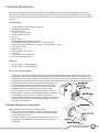
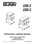
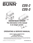
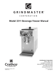
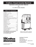
Unit 4 Preventive Maintenance
Unit Objectives
Given a realistic scenario depicting a machine requiring a preventive maintenance, the learner will be able to identify
which elements of a component need to be serviced without error.
Given a machine, all the necessary tools and safety equipment, the learner will be able to identify the components
that need to be serviced for the PM.
Preventive Maintenance
In order to maintain proper operation and long service life BUNN recommends performing the preventive maintenance every 6 months. Some of the PM items may require more frequent maintenance depending on the site conditions and usage. Failure to perform these procedures may result in damaged equipment and may not be covered by
warranty.
Tools Required:
•
•
•
•
•
•
•
•
•
•
•
•
•
•
•
•
Small & Medium standard blade screwdriver
Medium philip screwdriver
¼ inch ratchet set
Basic misc. size wrenches
2 Clean 5 gallon buckets
Sponge
Cloth or towel
Extended bristle brush (PN: 40500.1068)
Food grade lubricant (PN: M2550.0001 – 1 ounce Lubrifilm)
Krytox Grease (PN: 29563.0000 - .08818 oz. or M2548.1000 – Bulk oz.)
Condenser Cleaner
Rubber gloves
Safety goggles or face shield
Fin Comb
Vacuum with brush attachment
Mild non abrasive detergent
PM Parts
• ULTRA 1 PM Kit – PN: 34245.0002
• ULTRA 2 PM Kit – PN: 34245.0000
Prior to servicing the ULTRA:
•
•
•
•
•
The ULTRA has an optional menu setting that may alert the operator when Preventive Maintenance is due by displaying a message on the display, the message will read “Shaft Seal Maintenance Due”. The message will not shut down the machine if the service is not performed. The technician will need to be aware to reset the menu by answering “yes” in the “PM Complete ?” menu located in the programming section. Be aware that the menu might be password protected. Once you answered the menu with “yes”, the time and date is recorded for another six months to elapse.
The ULTRA may have the optional LAF and PAF accessories installed and will require turning off the main water supply.
Unplug or disconnect ULTRA and/or PAF Platform from power.
Drain hoppers of product into clean holding containers and ask store manager to store product in a cooler or refrigerator.
Remove hopper assemblies and ask store manager to perform the necessary cleaning procedure of the hoppers while you perform the preventive maintenance.
Preventive Maintenance Instructions
Step 1: Shaft Seal Maintenance ( PM Kit Required)
□□ Drain, remove and clean hopper; refer to the Operating and Ser vice Manual for proper cleaning procedures. Discard the hopper/
drum seal and faucet seal.
□□ Remove the #8 locking screws securing auger motor cover to the cooling drum mount assembly; remove cover and set aside for reassembly.
Figure 1
Bunn-O-Matic Corporation
27
□□
□□
□□
Remove the #8 locking screw on the lower right side (viewed from front) of the auger motor mounting bracket securing the auger motor run capacitor. Set capacitor aside with wires attached.
Disconnect the auger motor terminal from the terminal on the main wiring harness.
Remove the remaining #8 locking screws securing the cooling drum mounting bracket. Remove motor with mounting bracket.
□□
□□
□□
□□
□□
□□
□□
□□
□□
□□
□□
□□
Note: When removing or installing motor and shaft assemblies, be sure the split pins are turned to a position that will clear the torque sensor circuit board.
Pull the auger shaft assembly straight out of cooling drum. Inspect the shaft for abnormal wear.
From the front of dispenser, remove the seal and blue bushing from cooling drum and discard them.
Clean seal and bushing surfaces of the cooling drum very thoroughly. Open face of seal away
Lubricant is not required on any of the seals or bushings.
from tool
Refer to Figure 1, and slip new blue bushing into cooling drum.
Place seal on insertion tool as shown in Figure 2. Make sure open face of seal is toward cooling drum.
Push seal into bore until it is firmly seated; remove tool.
Place a small amount of “Krytox” lubricant (provided in kit in a plastic cap) on the end of the motor shaft (about 1 1/2”) and a thin film in the groove. Install auger shaft assembly onto the motor shaft. See Figure 3. Do not use too much “Krytox” lubricant. This is the only place “Kry
tox” lubricant is used.
Assemble motor/shaft assembly as shown in Figure 3, then install as
sembly into cooling drum. Make sure the pins do not hit the sensor board and cooling drum seal is not dislodged as the shaft passes Cooling Drum Seal
through.
Seal Insertion Tool
Secure motor and capacitor to the cooling drum mounting bracket. Install rear motor cover.
Refer to the Installation and Operating Manual for hopper assembly Figure 2
and installation procedures. Install new hopper/drum seals and faucet seals included in the kit. See Figure 1 and 4.
Remove and clean condenser air filter. See Figure 5.
Auger Shaft Assy
Refer to the Installation and Operating Manual, “Menu Function Index”. Scroll to menu “PM Complete?” and answer “YES” to reset the remind
er message “PM Due”.
Lube about 1 1/2” of shaft and in the
groove with BUNN P/N: 29563.0000
“Krytox” Lubricant
Figure 3
Faucet Seal
Figure 4
Figure 5
Step 2: Air Filter
□□ The air filter will need to be cleaned on a monthly basis or sooner dependent upon environment conditions and usage. Wash stainless filter in a sink with warm soapy water and dry.
28
Step 3: Cleaning the Condenser/Fins
□□ Use a soft cleaning brush attachment, gently vacuum the condenser coil fins.
□□ Using a flashlight, shine the light through the condenser fins to re-check for cleanliness or dirt between the fins.
□□ Heavy build-up of grease in the condenser may require the use of a commercial condenser cleaner.
□□ Follow the warning and safety instructions along with the how to instructions supplied with the cleaner.
Ultra Training Manual