1
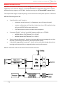
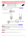
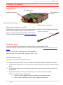
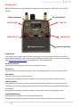
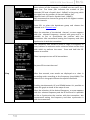
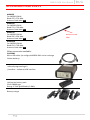
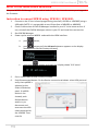
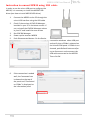
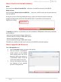
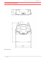
MPR30-IEM User Manual High performance True diversity Receiver SN: ________________ Rev. 06 (ref. FW v1.6) Date: 18 July 2014 MPR30-IEM User Manual 1 Rev. 06 MPR30-IEM User Manual Rev. 06 BRIEF DESCRIPTION MPR30 is a compact true diversity receiver designed for professional in-ear monitoring applications. This receiver features a real TRUE DIVERSITY configuration along with a unique wideband tuning range up to 232 MHz. Audio processing can be Stereo MPX or mono based. The output audio stage is especially design to have maximum audio peak-dynamic of 200 mW. MPR30-IEM is designed to be: “easy & quick to use” thanks to o automatic setup functions (i.e. frequencies, scan for best channels), o remote configuration utilities (thru infrared or micro-USB interface) using Wisycom MPR30 RX Manager application o OLED display with intuitive context menu navigation “extremely flexible”, with an incredible frequency agility up to 232MHz o MPR30-IEM-N: 470/700 MHz (TV ch 21/49) o MPR30-IEM-M:566/798 MHz (TV ch 33/61) “best in class performances”, thanks to the latest Wisycom technology the unit has extreme RF sensitivity and immunity and superb audio quality “a durable & upgradable investment”, thanks to the very robust design (aluminium housing) and the possibility to upgrade/enhance units performances. Above a schematic with an overview of main receiver functions. 2 MPR30-IEM User Manual Rev. 06 SAFETY INSTRUCTION Read this safety instruction and the manual first Follow all instructions and information. Do not lose this manual. Do not use this apparatus under the rain or near the water. Do not install the apparatus near heaters or in hot environments, do not use outside the operating temperature range. Do not open the apparatus, only qualified service technician are enabled to operate on it. The apparatus needs servicing when it is not properly working or is damaged by liquids, moisture or other objects are fallen in the apparatus. Use only accessories or replacement parts authorized or specified by the manufacturer. Clean the apparatus only with dry cloths, do not use liquids. Report the serial number and the purchasing date in front of the manual. It is needed to have proper replacement parts or accessories from the manufacturer. When replacement parts are needed, use only replacement parts authorized from the manufacturer. Substitution with not authorized parts could result in electric shock, hazards or fire. Keep attention on all the labels with warnings or hazards on the apparatus. The apparatus is intended for professional use; anyway the manufacturer alerts the user that the headphone output power of the apparatus could exceed the level of 85 dB(A) of sound pressure level and this could be dangerous for the hearings. Do not use the headphone with high power level or for long time. Reduce the power or suspend the hearing in case of any kind of hearing problem. 3 MPR30-IEM User Manual Rev. 06 BATTERIES MPR30-IEM works with standard camera battery: 2xIEC-LR6 1.5 size-AA alkaline or NiMh rechargeable KLIC 8000 (lithium-ion, rechargeable) Ricoh DB-50 (lithium-ion, rechargeable) DR9708 Duracell (lithium-ion, rechargeable) Battery status can be checked on OLED display or looking the status of LED indicator ON. Lithium-ion battery can be charged through A. dedicated charger B. integrated micro-usb-B connector For B item, the charging status can be checked looking the status of LED indicator ON. The receiver can be used also during the batteries charging with lithium rechargeable batteries inside. Don’t use the receiver without batteries . The receiver powered thru micro-USB without batteries doesn't work correctly. DO NOT operate the device with some new and some old batteries. Always replace ALL BATTERIES. Remember to remove the batteries when the device is not in use. 4 MPR30-IEM User Manual Rev. 06 PRODUCT OVERVIEW Upper Panel ON LED indicator Headphone Output On/Off/Volume control SMA connector Antenna B SMA connector Antenna A SMA antenna Connector A and B MPR30-IEM is supplied with two couple of antennas. According to the working band, different antenna models can be supply. All the models have Antenna Code label black cap and a black label with code in white colour. For more details see the section Accessories and Parts Headphone Output The audio headphone output with 3.5 mm stereo jack socket lockable (TRS). Audio level can be adjusted with the Volume control knob and the Audio settings> Pwr. Limit menu. Maximum output power: 2x150mW @ 32Ω, 2x200mW@16Ω Pin Assignment: Tip = left (hot), Ring = right (hot), Sleeve = Gnd On/Off/Volume control The control knob in the upper panel allows: To switch the receiver ON: turn the control knob volume control clockwise until it clicks To switch the receiver OFF: turn the control knob volume control counter clockwise until it clicks To adjust the volume: turn the control knob volume control until the volume set has the desired level. To disable the lock volume: turn off and turn on the receiver within 1 second. NOTE: turn off and turn on the receiver within 1 secondMPR30 restarts without the initialization phase after 1 second MPR30 restarts with complete initialization 5 MPR30-IEM User Manual Rev. 06 Front panel MPR30-IEM allows an easy and quick configuration using buttons, RGB LED’s and an OLED display. ON Led Indicator SCAN/DOWN Button MENU/SELECT Button RF Led Indicator SYNC/UP MENU/EXIT Button Infrared Interface (IR) OLED Display The receiver has a high contrast display. Pushing one of the 4 buttons while the receiver is active (but the display is off), turn on automatically the display. After a time-out user setting (see Display>Off timeout menu) the display turns off automatically. SEL & EXIT Buttons Push the 2 buttons together to enter on the function menu SEL Button Push this button to navigate function menu’s and keep pushing to save the chosen setup EXIT Button Push this button to turn off the display. During menu navigation push this button to exit from current menu (escape function). SYNC/UP Button Push and keep this button to start a synchronisation with a Wisycom transmitter (follow instructions on display). Before starting synchronization IRDA must be enabled on Wisycom transmitter. During menu navigation push this button to move -up and select the previous item. SCAN/DOWN Button Push and keep this button to start the automatic scan. During menu navigation push this button to move-down and select the previous item 6 MPR30-IEM User Manual Rev. 06 charging status battery status Tuning phase power up ON & RF Led Indicators (Firmware rel. v0.2) ON red RF off red off/on red off/on fixed green off fixed green blue after the tuning phase, a stereo signal is received fixed green green after the tuning phase, a mono signal is received fixed green slow blinking green fast blinking green red blinking blue blinking green fixed green white on/off the batteries charge of the receiver is good (>25% lifetime) the batteries charge of the receiver is low (<25% lifetime) on/off on/off WHEN when the receiver is power on, during the power up phase when the receiver is power on, after the power up phase when the receiver is power on, during a frequency change phase (see Gr-Ch or Frequency menu) after the tuning phase, no transmitter is received off off the batteries charge of the receiver is very low (<12% lifetime) battery error during batteries charging off during batteries charging off during batteries charging green/ blue device in bootloader mode* MEANING the receiver is not ready to use, wait the status display on display the PLL is not locked on the select frequency, wait for lock ( about 1second or less) the PLL is not locked on the select frequency, wait for lock the receiver is locked on the select frequency, the batteries charge is good, no transmitter is synchronized with the receiver, no output audio available the transmitter is correctly tuned, the bars in the status display show the RF levels received from antenna A and B the transmitter is correctly tuned, the bars in the status display show the RF levels received from antenna A and B, in the status display M symbol appears upper the battery level the batteries charge of the receiver is good change or put on charge the batteries as soon as possible change or put on charge the batteries immediately change the batteries the batteries are charging (<90% of complete charge) the batteries are charging (≥90% of charge reached) charge complete * to put the MPR30-IEM in boot mode: power on the device push and keep both UP and DOWN buttons for few seconds (until the led indicators light up, then release the buttons) 7 MPR30-IEM User Manual Rev. 06 PUTTING THE DIVERSITY RECEIVER INTO OPERATION Insert the batteries Connect the headphones Connect the 2 antennas on the SMA connectors Turn the knob control clockwise until it clicks and verify on the display the Antenna model to use (if the connected antennas on the receiver is different from the antenna model indicate on the display, power off the receiver and replace them with the proper model of antennas) after the power up phase, the Status display is showed on the OLED display verify the setting and eventually adjust the settings using the Operating Menu Status display - Receiver Name (ex. MPR30-IEM RX) - Group (ex. Gr:00) and Channel (ex. Ch:01) - Frequency (ex. Fr:697.000 MHz) - Squelch (ex. Sq:12dBuV) - Mode (ex. Stereo) CSquelch level A B C A. B. RF Level Antenna A and B (range 5 ÷ 70 dBµV) Between the two RF bars there is a dotted line where the first 3 dots indicate 6/8/10dBµV and the other 15 dots indicate the rest of the range (from 14 to 70dBµV with step of 4dBµV An orizzontal sign in a central row shows the setted Squelch level C. deviation level (range of 54 dB, bar with 3dB steps; upper level= 0dB, under level =-54dB) the upper symbol: indicates presence of audio output S T indicates absence of audio output (RF level < Squelch) indicate absence of audio output (no pilot tone detected) NOTE: in case of absence of pilot tone and RF level < Squelch, the symbol display D. batteries level for MPR30-IEM receiver the upper symbol: indicates receiving of a mono signal M S 8 indicates receiving of a stereo signal will be MPR30-IEM User Manual DISPLAY MENU Audio Settings Out mode Stereo/Mono/Mix Balance Vol. boost L|R Low (-12÷+12) Hi (-12÷+12) -12÷+12dB Output load 32Ω/16Ω Pwr limit OFF/100mW/50mW/30mW Equalizer Gr-Ch Frequency Edit RX Squelch Scan Rev. 06 GR (0÷39) CH (0÷59) N: 470.000÷700.000 M: 566.000÷798.000 *Only using lithium battery OFF*-0/3/6/9/12/15/18/21/24//28/32/36/40/46 dBµV Channel GR 00 - 39 Groups more groups (max 10) Scan now freq. Min/ freq. Max/ Squelch scan Freq step (100 or 200 kHz) Scan BTN Channel/Groups/Freq View last Deploy Name MENU Quick Menu Settings Display Infrared LED Sync Advanced Lock volume Pilot Squelch Model Range 470÷700 Serial Battery S2334437 Version BL App Version Option 3.71 Volt Errors 0 Restore 1/2/3/4/5/6/Factory Save 1/2/3/4/5/6 FW HW Preset 9 0÷5 5÷60 steps 5 10÷120 steps 10 - OFF Yes/No Yes/No Add Load Delete Delete all MPR30-IEM Clone Info 12 characters ex. RECEIVER-123 Bal /Mix ; Clone ; Off Contrast Low timeout (sec) Off timeout (sec) Full/Alarm/OFF 00÷23 default/0/... 00÷23 It appears if exist at least 1 clone v1.5 v1.4d v1.54d 6 N Clone parameters Preset parameters MPR30-IEM User Manual Rev. 06 From Status Display push SEL and EXIT together to enter on the Main menu Use UP/DOWN to navigate on all available menus Push SEL to select a menu item Use UP/DOWN to move on the different parameters of the menu Push SEL to modify the parameter menu Use UP/DOWN to change the parameter value Keep push SEL to save changing Push EXIT to return on the Main Menu Push EXIT to return on the Status display Audio settings The Audio settings menu allows to configure the audio output. PARAMETER SETTING MEANING The left and right signals are available as usual. The Balance Stereo setting serves to adjust the balance between the left and right stereo signal. The left-right signals are mixed and are available as a mono Mono signal in both headphone channels. It is not possible to Out mode adjust the level of the 2 channels as in Out mode Mix. The left-right signals are mixed and are available as a mono signal in both headphone channels. Mix The Mix mode setting serves to adjust the relative levels of the two separate channels in the mixer mono signal. This menu allows to of adjusting the gain of low and high frequency components (bass and treble) within the audio signal. Low and High Equalizer 1. Push UP/DOWN button to increase/decrease the frequencies gain of the Low frequencies (50Hz) -12dB/+12dB 2. Push SEL button to shift on High frequencies, 1dB steps 3. Push UP/DOWN button to increase/decrease the gain of the High frequencies (10kHz) 4. Keep push SEL button to SAVE This menu allows to increase or decrease the volume of the output headphones, selectable from -12 dB to 12 dB. Set the -12/-6/0/3/6/9/12dB Vol. boost appropriate volume boost and then adjust the volume with the control knob. Set the Output load according to the impendence of the 16Ω/32Ω Output load headphones connected This menu allows to limit the power output. If set to OFF (only using lithium Pwr limit OFF(only lithium battery), there is no power limit control. If battery) / 100mW / set to OFF using alkaline or NiMH batteries, the receiver set 50mW / 30mW automatically the max value permitted (100mW) NOTE: When the volume knob is rotated, appears a screen with a volume bar and the values of Pwr limit, Outpul load and Vol. boost 10 MPR30-IEM User Manual Rev. 06 Edit RX The Edit RX menu allows to configure the radio frequency settings. PARAMETER Gr-Ch Frequency Squelch SETTING 0÷39 groups 0÷59 channels 470÷700 MHz for MPR30-IEM-N 566÷798 MHz for MPR30-IEM-M OFF or 0/3/6/9/12/ 15/18/21/ 24/28/32/ 36/40/46dBuV MEANING Select current group and channel. Group name and channel frequency are displayed on the right. If the specific group/channel is not locked, the frequency can be edited in this menu. This menu allows to disable the RF squelch or to setup the desired squelch level in dBuV (note 0 dBuV is equal to 107 dBm). It allows making three types of scan over a desired channel, group or frequency. MPR30-IEM manages up to 2400 custom frequencies organized in 40 groups of 60 channels each. This extreme flexibility makes the scan function very flexible. This function can be called also using the dedicated DOWN&SEL buttons pushed together. “Squelch scan” indicates the threshold below which a channel is considered as free or almost free. Scan “Scan BTN” is the parameter to set the rapid function called pressing DOWN&SEL buttons together. It’s possible to set Channel, Group or Frequency scan. “View last” allows to see the result of the last scan operation. “Deploy” allows to send to a MTK952 the last scan. From the transmitter it’s possible to see the graphic of the last scan and choose the frequency to tune. (*)As per Wisycom standard, group 00 and group 01 or 09 are special; respectively the “center frequency” (474,482/… MHz) and the intergap frequency (i.e. 470/478/486/… MHz). A scan on group 00 will reveal in few seconds the overall DVB-T occupation on the area, while a scan on group 01 will give possible working frequency, usable also in presence of strong DVB-T signal (sort to speak working in the band-guard of 2 digital television channels). 11 MPR30-IEM User Manual Rev. 06 “Scan now” menu The following table lists the three types of scans that can be performed Once started a Channel scan operation the receiver asks for group to be used*. Press and hold the SEL button to select the group to scan. Then it prompts to turn off all transmitters. So press SEL to start the scan! Channel After few seconds, scan results are displayed sorted by level, making easier to pick up the best one. The dotted line in the graph indicate the squelch threshold. Under the graph are reported the following parameters: Ch: Channel Rank: Ranking position Freq: Frequency Lev: RF level Pushing simultaneously UP and DOWN button, the results can be also displayed on a chart in ascending order according to the number of the channel. After the selection of the desired channel, a screen appears with the selected frequency, channel and group and it is possible to Set or Synchronize the receiver with the transmitter. We recommend setting the frequency and then synchronize it with the transmitter. If the scan is done on Groups, you can choose a maximum of 10 groups from among the 40 groups shown in the table (Press the SEL button to select and press it again to deselect). In the upper left shows the number of the selected group and the number of selected groups, while in the upper right corner there is the item "START" to start the scan. Groups To select START, go to the box 39 and press the "UP" button or go to the box 0 and press the "DOWN" button, so press SEL to run the scansion. Then it prompts to turn off all transmitters. So press SEL to start the scan! 12 MPR30-IEM User Manual Rev. 06 After few seconds, scan results are displayed on a histogram. Each column of the histogram is divided into two parts by a black line. The lower part indicates the number of free channels (RF level < Squelch level - 6dBµV) in the group, while the upper one the number of channels almost free (Squelch level < RF level < Squelch level - 6dBµV). We recommend to choose the group with the highest number of free channels. Press SEL to select the desiderate group and choose the channel as in “Channel scan” After the selection of the desired channel, a screen appears with the selected frequency, channel and group and it is possible to Set or Synchronize the receiver with the transmitter. We recommend setting the frequency and then synchronize it with the transmitter. The Frequency scan allows to select a range of frequency to scan, between a maximum and a minimum value and the step with which to perform the scans. Press and hold the SEL button to confirm. Then it prompts to turn off all transmitters. So press SEL to start the scan! Freq After few seconds, scan results are displayed on a chart in ascending order according to the frequency (step 1MHz). The dotted line in the graph indicate the squelch threshold. Pushing simultaneously UP and DOWN button it’s possible to zoom the graph to show all the steps of scan After the selection of the desired frequency, a screen appears with the selected frequency and the RF level and it is possible to Set or Synchronize the receiver with the transmitter. We recommend setting the frequency and then synchronize it with the transmitter. 13 MPR30-IEM User Manual Rev. 06 Settings The Settings menu allows to configure main settings of the device. PARAMETER SETTING MEANING The name menu allows to change the name of the receiver. This is the name displayed in the top of the Status display and it is the name sent to the 12 case-sensitive alphanumeric transmitter with the sync function (for the Name characters transmitter with this advanced capability). Use the UP/DOWN buttons to change the selected character and push SEL button to switch to the next character. The quick menu is displayed pushing UP or DOWN buttons when the receiver is on the Status display. Set to Bal/Mix to enter quickly to the Balance/Mix mode menu (according to the Out mode configured). Quick Bal/Mix ; Clone ; Off Menu Set to “Clone” to enter quickly to the Load clone menu Set to “Off” for disable this function (if is set “Off” and UP or DOWN buttons are pushed, nothing happens). Contrast 0÷5 Change contrast display from 0 (min) to 5 (max). Low timeout sets the timeout from 5 to 60 seconds Low timeout 5÷60 (steps 5) (5sec steps) to decrease the brightness display. Display Off timeout sets the timeout from 10 to 120 10÷120 (steps 10) Off timeout seconds in 10 sec. steps to turn off the display. or OFF With OFF setting the display never turns off. 3 LED setting are available: Full Full: LED indicators works normally; Alarm Alarm: LED indicators lights up only when an alarm LED OFF happened; OFF: LED indicators remain off. Infrared By this menu, MPR30-IEM can be connected to IRDA for setup or firmware upgrades. When the Infrared interface is active, the following screen is displayed. NOTE: while in this menu display is not automatically turned off. 14 MPR30-IEM User Manual Rev. 06 Sync The SYNC function is useful to tune a transmitter on the same frequency of the receiver via the IR interface. Before starting the sync function tune the receiver on desired channel, manually or using the SCAN utility. After this, enable the IR interface on the transmitter. Now press UP&EXIT buttons together or enter in the Sync menu to start the SYNC function. Keep the IR window of the transmitter in front of the IR window of the receiver and, as soon as the connection is done, the receiver will send to the transmitter all the information needed. If the operation is not possible, (i.e. the frequency range of the transmitter is not compatible with the frequency of the receiver), the display will show an error message. If the transmitter has the function “NAME” enabled, when the sync function is completed it will show the same name of the synchronized receiver. Advanced The Advanced menu allows to manage advanced settings. PARAMETER SETTING MEANING If set to Yes, during the “max brightness” of the display an open lock is displayed on the Status Display. After the “Display -Low timeout” the lock Yes / No becomes closed and the lock volume is enabled. Lock volume To enable the volume setting it is necessary turn the volume knob below the previous setting or make a “quick turn off – turn on”. When the Pilot tone is enabled, the audio output is muted unless the correct carrier is detected (19kHz). Yes / No When the Pilot tone is disable, the audio output is Pilot Squelch muted if RF level < Squelch level. For the presence/absence of audio output, check the upper symbol in the status display. Add 00÷23 To add a clone Load Default/00÷23 To load a clone * Clone * Delete 00÷23 To delete a clone * Delete all To delete all the clones * * A clone is a partial configuration of the MPR30-IEM which can be copied from a receiver to another using the IRDA interface. It consists of the same parameters of pre-set configuration for less than display, quick menu and headphones parameters (see the Operating menu for more details). From firmware version v1.3 the MPR30-IEM is able to manage up to 24 clones (from 00 to 23). The menus of the clone management allow to add/load and delete a clone. * It appears if exist at least a1 clone 15 MPR30-IEM User Manual Rev. 06 How to add a clone Out mode Balance Equalizer Vol boost Pilot tone Gr-Ch Squelch RX Name Clone name Enable the IRDA interface on the RX from which take the configuration (Infrared menu) Put the receivers face to face At the end of the process the name of the clone will be identify with the name of the receiver. Enter in the Add menu and select the wanted clone number. Then push SEL to start the IRDA communication. How to load a clone Use Clone>Load menu or UP/DOWN button (if the quick menu is configured to clone) to load a clone. Afterwards push the arrows to change clone, SEL to activeted the clone and EXIT to exit without changing. Ex. The configuration saved before the loading of the clone is saved on the clone named “default”, therefore loading the default “clone” allows to return with the previous settings. The following arrows displayed near the clone number indicates the currently clone loaded. 16 MPR30-IEM User Manual Rev. 06 Loading a clone, all the clone parameters are set on the receiver. The follow icon appears on the right of the display indicating that a clone is loaded. The number and the name of the clone are displayed on the top of the display menu and a brief list of the main parameters are displayed on the status menu. Name of the clone Number of the clone symbol to indicate that a clone is loaded is loaded Main parameters NOTE: the clones are saved on the EPROM and remains saved also after a reboot of the device. NOTE: If a clone is loaded and then a reboot is executed, the MPR30-IEM always restarts with the previous configuration (default clone). NOTE: When a clone is loaded, it's not possible change the parameters NOTE: When a clone with Power limit set to OFF is loaded on the receiver but the receiver isn’t using Lithium battery, the power limit is set automatically to the max value permitted for no lithium battery (that is 100mW). Info the INFO function shows many important features or information of MPR30-IEM receiver: PARAMETER Model Range Serial FW HW Battery Errors MEANING Wisycom receiver model Frequencies range of working Serial number Version * Firmware version BL Bootloader version App Application version Version Hardware version MPR30-IEM Options Option N= freq. range 470÷ 700 MHz, M= freq. range 566÷ 798 MHz Batteries voltage Number of errors. If the number of errors is > 0 push SEL button to enter on the Errors list. For each error a brief description and the error code is showed. For more information, please see the Error List section. * The Firmware Version recaps BL (Bootloader Version) and App (Application version). 17 example MPR30-IEM 470-700 S2334437 V1.6 V1.4d V1.63d 6 N 3.71 Volt 4 MPR30-IEM User Manual Rev. 06 Preset This menu allows to load/save 6 user presets or load the Factory configuration. PARAMETER SETTING Restore 1/2/3/4/5/6/Factory Save 1/2/3/4/5/6 MEANING Select the Restore submenu and chose the presets to load: user presets or Factory preset. Push and keep SEL button to load the preset. Select the Save submenu and chose the user presets to save. Push and keep SEL button to save the preset ERROR LIST When an error occurs, the receiver A. shows a message on the display and for some error types B. increases the errors counter in the info menu C. inserts the error type and code on the error list in the info menu When the error is solved, the message on the display disappear, but the error information (code and description) are available on the error list in the Info menu (only for some error, see the below table). NOTE1: When the receiver is reset the error information (code and error type on the list) are lost, with the exception of errors codes 87/88/89/8A. NOTE2: To reset the error counter and the errors list, it is necessary to contact Wisycom. HW init failed Message on display (A) HW init failed Battery Low Battery Low Battery charge failed Battery charge failed I2C communication error Device ID copy1 invalid Memory recovered Device ID copy2 invalid Memory recovered RF copy1 invalid Memory recovered RF copy2 invalid Memory recovered PLL unlocked I2C communication error Device ID copy1 invalid Memory recovered Device ID copy2 invalid Memory recovered RF copy1 invalid Memory recovered RF copy2 invalid Memory recovered - I2C access failed 04 Device ID copy 1 87 Device ID copy 2 88 RF mem copy 1 89 RF mem copy 2 8A PLL unlocked 84 CH mem header - CH mem header 85 Param mem header - Param mem header 86 Errors 18 Error type (C) Code (C) MPR30-IEM User Manual Rev. 06 TROUBLESHOOTING Problem Possible cause “HW init failed” message appears on the display “Battery Low” message appears on the display “Battery charge failed” message appears on the display “I2C communication error” message appears on the display “Device ID copy1 invalid Memory recovered” message appears on the display “Device ID copy2 invalid Memory recovered” message appears on the display “RF copy1 invalid Memory recovered” message appears on the display “RF copy2 invalid Memory recovered” message appears on the display The Serial Number of the receiver in the Info menu is UNCAL The errors 87 (Device ID copy 1 ) and 88 (Device ID copy 2) appear in the errors list The errors 89 (RF mem. copy 1 ) and 8A (RF meme. copy 2) appear in the errors list The receiver is not able to tuned on the selected frequency and the ON led indicator remains red 19 Error during the hardware initialization phase Low level on the battery Possible solution -reset the receiver, if the problem persists send to repair at Wisycom Repair Centre - change batteries or - recharge the batteries Error during batteries charger (damage batteries or wrong batteries) - change batteries Communication error on bus I2C - send to repair at Wisycom Repair Centre Error during the initialization phase. The CRC-16 check of device data (copy 1) detects error. - nothing (the receiver automatically replace the corrupt copy1 with copy2) Error during the initialization phase. The CRC-16 check of device data (copy 2) detects error. - nothing (the receiver automatically replace the corrupt copy2 with copy1) Error during the initialization phase. The CRC-16 check of RF data (copy 1) detects error. - nothing (the receiver automatically replace the corrupt copy1 with copy2) Error during the initialization phase. The CRC-16 check of RF data (copy 2) detects error. - nothing (the receiver automatically replace the corrupt copy2 with copy1) Error during the initialization phase. The CRC-16 check of device data (copy 1 and copy 2) detects error. - send to repair at Wisycom Repair Centre Error during the initialization phase. The CRC-16 check of device data (copy 1 and copy 2) detects error. - If the Serial Number in the Info menu is UNCAL, then send to repair at Wisycom Repair Centre - If the Serial Number in the Info menu is not UNCAL, continue to use the receiver Error during the initialization phase. The CRC-16 check of RF data (copy 1 and copy 2) detects error. - contact Wisycom for more information Error during frequency tuning - try to change the frequency, if the problem persists send to repair at Wisycom Repair Centre MPR30-IEM User Manual The frequencies of all the channels and groups is equal to the lower frequency of the receiver Error in the channel memory during the initialization phase. (according to the receiver 470 MHz for MPR30-IEM-N 566 MHz for MPR30-IEM-M) Configuration mismatch Error in the parameter memory Rev. 06 if the error code 85 appears on the errors list: - load a new frequency file (wdf) in the frequency memory of the receiver and - contact Wisycom for more information if the error code 86 appears on the error list: - load a preset configuration using Preset menu and - contact Wisycom for more information If a problem not listed in the above table occurs or if the problem cannot solved with the proposed troubleshooting, please contact support service at [email protected] or [email protected]. 20 MPR30-IEM User Manual Rev. 06 ACCESSORIES AND PARTS AWNL30 For MPR30-IEM-N Band 470 ÷ 574 MHz Antenna Code label 520 AWNH30 For MPR30-IEM-N Band 574 ÷ 700 MHz Antenna Code label 634 AWML30 For MPR30-IEM-M Band 566 ÷ 654 MHz Antenna Code label 590 AWMH30 For MPR30-IEM-M Band 654 ÷ 798 MHz Antenna Code label 725 Other accessories available: CAUSBM1 Micro USB cable (to configure MPR30-IEM and to recharge lithium battery) UPK300E Infrared programming kit (interface + software) USB interface MPRLBP Lithium-ion battery pack CS-KLIC8000 type Rating: 3.7Vdc @1600mAh (5.9Wh) MPRBAT Battery charger 21 Antenna Code label MPR30-IEM User Manual Rev. 06 HOW TO USE MPR30 RX MANAGER Wisycom MPR30 RX Manager can be used to load or save the channels memory and upgrade the firmware. Instruction to connect MPR30 using UPK300 / UPK300E: 1. 2. 3. 4. 5. 6. 22 Connect to the PC the infrared programming interface (UPK300 or UPK300E) using a USB cable (NOTE: it is not possible to use IR interface of MRK950 or MRK960) Check if the version of ENG RX Manager installed in your PC is the latest version. If not, uninstall the ENG RX Manager actives in your PC and install the new version Run ENG RX Manager Power up the receiver MPR30 and enable the IRDA interface: a. push button, b. push button until that Infrared submenu appears on the display (Headphones>Edit RX>Display>Infrared) c. push again button and check the display shows ‘IR IF active’ Put in contact MPR30 and UPK300/UPK300E Push Disconnected button. On the Device connection windows select UPK port and verify that upk300 is selected on the Silabs USB devices panel. If upk300 device is not showed, push Refresh button and/or try to disconnect and reconnect the USB cable connected to the UPK300. Then click OK. MPR30-IEM User Manual 7. 23 Rev. 06 If the connection is ended well, the Connected icon is showed on the top of the panel and “Connected on USB by UPK” is displayed on the information panel MPR30-IEM User Manual Rev. 06 Instruction to connect MPR30 using USB cable: In order to use the micro USB port to configure the MPR30, it is necessary to install the MPR30 USB driver (see How to install MPR30 USB driver) 1. 2. 3. 4. 5. Connect the MPR30 to the PC through the micro USB interface using the USB cable Check if the version of ENG RX Manager installed in your PC is the latest version. If not, uninstall the ENG RX Manager actives in your PC and install the new version Run ENG RX Manager Power up the receiver MPR30 Push Disconnected button. On the Device connection windows select USB port and verify that a COMx is selected on the Virtual COM panel. If COMx is not showed, push Refresh button and/or try to disconnect and reconnect the USB cable connected to the MPR30. Then click OK. 6. 24 If the connection is ended well, the Connected icon is showed on the top of the panel and “Connected on COMx” is displayed on the information panel MPR30-IEM User Manual Rev. 06 How to load/save channels memory Write: Push the button Write from WDF file… and select the wdf file to load on the MPR30. Read and save: Push the button Read and save to WDF file… , insert the .wdf file name and the path where to save the wdf file. During the process of writing/reading & saving, a green bar below the panel shows the progress of the process and on the information panel it is possible to verify what the application is doing. To Modify the wdf file, it is possible to use the spreadsheet FREQUENCY 2010 v16.xls available on the website: - open the file and enable changes and macro - load the wdf file clicking on READ WDF button - execute the desiderate changes - save the wdf file clicking on SAVE WDF button The WDF thus modified can be used to write on the MPR30’s channels memory. How to upgrade the firmware Select FW upgrade panel 1. Push the Browse button and select the upk file 2. Put the receiver in bootloader mode: power on the MPR30 keep pushing both the arrow bottons). When the receiver is in bootloader mode, all the led in the front panel are turn on. 3. Click on Start button and check the progress of the upgrade process in the green bar 25 MPR30-IEM User Manual Rev. 06 TECHNICAL SPECIFICATIONS • Frequency ranges • Switchable channels • Switching-window • Frequencies • Frequency error • Temperature range • Modulation • Peak deviation • “A” / “B” antenna in • Antenna input imp. • Sensitivity • Co-channel rejection • Adjacent chan. Sel. • Spurious rec. Rej. • IF image rejection • Intermod. rejection • IIP3 • Spurious emissions • Noise Reduction • AF bandwidth • Frequency response • Distortion • SND/D ratio • Stereo separation • Display • Powering • Weight • Headphone-output • Battery life : MPR30-IEM-N option 470÷ 700 MHz MPR30-IEM-M option 566 ÷ 798 MHz other ranges are available on request in 470÷798 MHz : 40 groups of 60 channels fully user programmable. : up 232 MHz. : microprocessor controlled frequency synthesizer circuit, with 25 kHz minimum step. The frequencies can be easily PC reprogrammed with the optional UPK 300E Programming Kit. : < ± 2.5 ppm, in the rated temperature range. : -10 ÷ +55 °C. : FM, (19 kHz sync carrier) : ±48 kHz : with sturdy connectors. : 50 ohm sma type (SWR < 1:2; typ. 1:1.4). : 2 µV ( 6 dBµV), for SND/N > 52 dB; in the whole switching-window [1]. : > 2.5 dB. : > 80 dB typical (for channel spacing ≥ 400 kHz). : > 100 dB. : > 90 dB. : > 76 dB. : > +10 dBm typical. : < 2 nW (typical = 0.1 pW). : ENR (Wisycom Extended-NR) : 30 Hz ÷ 15 kHz. : ± 0.5 dB in the 30 Hz ÷ 15 kHz range. : 0.3 % typical. : 90 dB typical [1] : > 60 dB : Display OLED 128x64 (white) : 2 x IEC-LR6 1.5V size-AA alkaline or rechargeable elements : 100 g approx. without batteries : Stereo Plug 3.5mm(TRS) Locking (M6 x 0.5 thread) with 2 X 150mW @ 32 Ohm : approx.. 5 hours (alkaline batteries), 8 hours (lithium batteries) NOTE [1]: RMS value, 22 Hz / 22 kHz, unweighted. The MPR30-IEM receiver complies with ETSI specifications: ETS 300 422. 26 MPR30-IEM User Manual MECHANICAL DRAWING Note: unit is mm 27 Rev. 06 MPR30-IEM User Manual 28 Rev. 06 MPR30-IEM User Manual Rev. 06 ITALY ONLY Obblighi di informazione agli utilizzatori Modello di informazioni agli utenti dei prodotti di tipo “professionale” INFORMAZIONE AGLI UTENTI ai sensi dell’art. 13 del Decreto Legislativo 25 luglio 2005, n. 151 “Attuazione delle Direttive 2002/95/CE, 2002/96/CE e 2003/108/CE, relative alla riduzione dell’uso di sostanze pericolose nelle apparecchiature elettriche ed elettroniche, nonché allo smaltimento dei rifiuti” Il simbolo del cassonetto barrato riportato sull’apparecchiatura o sulla sua confezione indica che il prodotto alla fine della propria vita utile deve essere raccolto separatamente dagli altri rifiuti. La raccolta differenziata della presente apparecchiatura giunta a fine vita e’ organizzata e gestita dal produttore. L’utente che vorrà disfarsi della presente apparecchiatura dovrà quindi contattare il produttore e seguire il sistema che questo ha adottato per consentire la raccolta separata dell’apparecchiatura giunta a fine vita. L’adeguata raccolta differenziata per l’avvio successivo dell’apparecchiatura dismessa al riciclaggio, al trattamento e allo smaltimento ambientalmente compatibile contribuisce ad evitare possibili effetti negativi sull’ambiente e sulla salute e favorisce il reimpiego e/o riciclo dei materiali di cui è composta l’apparecchiatura. Lo smaltimento abusivo del prodotto da parte del detentore comporta l’applicazione delle sanzioni amministrative previste dalla normativa vigente. 29 MPR30-IEM User Manual 30 Rev. 06 MPR30-IEM User Manual Wireless System Communications Via Spin 156 I-36060 Romano d’Ezzelino Italy Tel. +39 -0424 -382605 Fax +39 - 0424 - 382733 www.wisycom.com e-mail: [email protected] 31 Rev. 06