1
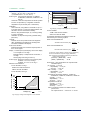
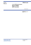
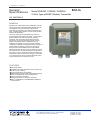
<<Contents>> <<Index>> General Specifications Model PH202G, PH202S, PH202SJ 2-Wire Type pH/ORP (Redox) Transmitter GS 12B07D02-E GENERAL Flexibility, low maintenance and low installation costs are among the benefits of the EXA PH202 pH/ORP transmitter. Designed to meet the exacting requirements of measuring pH and ORP in the modern industrial environment, it contains many features to ensure peak precision whatever the application. This 2-wire (loop powered) transmitter is housed in a robust IP65 field mountable case. HART® communication is also available. The need for expensive cabling is minimized. The famous EXA sensor diagnostics are enhanced by an improved impedance check, and the addition of a logbook feature. Calibration history is available in the display, and is used to store important configuration, calibration and diagnostic data. Prediction of sensor failure is possible by reference to the logbook. Microprocessor-aided calibration uses internal buffer tables and stability checking to ensure maximum accuracy with minimum effort. Process temperature compensation enhances accuracy in applications where the influence of temperature is seen in process pH changes. pH and ORP or rH measurements can be made simultaneously when an appropriate sensor combination is used. FEATURES d Universal pH/ORP d Possible to input high impedance reference electrode d On-line sensor checking d Process temperature compensation d Differential input amplifier with equipotential screening d Freely configurable ITP, slope and asymmetry d Easy to use EXA control panel d Password protection for all levels of software d HART®, PROFIBUS-PA, FOUNDATION Fieldbus H1 communications Yokogawa Electric Corporation 2-9-32, Nakacho, Musashino-shi, Tokyo, 180-8750 Japan Tel.: 81-422-52-5617 Fax.: 81-422-52-6792 GS 12B07D02-E ©Copyright Jan. 2000 1st Edition Jan. 2000 8th Edition Feb. 2008 2 <<Contents>> <<Index>> ACCURATE pH MEASUREMENT 1. Electrode selection In order to make precise pH/ORP measurements, there are a number of pre-requisites. Special attention should be paid to the choice of the sensors to ensure compatibility with the chemical composition of the process fluid. The speed of response required, the solids content and the flow rate of the fluid are also contributory factors. The GS12B07B02 -E general specifications cover the choice of sensors. PROCESS TEMPERATURE COMPENSATION The figure below shows the strong change in pH with temperature, caused by the dissociation constant of water changing. This effectively shifts the neutral point from pH7. In order to reliably control the pH of solutions it is necessary to compensate for the changes. The PH202 transmitter has a simple-to-operate system of process temperature compensation to provide optimum accuracy and best control. An application where this is particularly important is in the measurement of alkalized boiler feed water. 2. Signal processing (pH/ORP) 3. High performance transmitter The PH202 provides excellent noise rejection, minimizing the stray signals that can affect industrial pH measurements. Earth loop currents in damp and damaged cabling are eliminated by the equipotential screening. It offers a simple and effective process temperature compensation in addition to the usual compensation to the Nernst equation. pH at process temp. With the correct sensor configuration, the PH202 can measure pH and ORP. pH 11.00 at 258C becomes pH 9.80 at 808C 4. Maintenance It is important that the system be well maintained to make precise pH/ORP measurement. The electrodes must be properly cleaned and regularly calibrated. Yokogawa online cleaning systems may be used where there is significant fouling of the sensors. Other influences from the electrode holders can be less obvious, but important none the less. Well designed fittings make it easy to provide the routine maintenance needed for best accuracy. Flowthrough submersion, suspension and float types of holders are available. pH at reference temp. F2.EPS 3-LEVEL OPERATION The PH202 transmitter uses a 3-level operating system to take full advantage of the microprocessor while retaining the traditional simplicity of a 2-wire transmitter. Advanced functions are separated from conventional operation to avoid confusion. They can be activated as required for each individual application. HART COMMUNICATION One of the features of smart field devices is their ability to detect faults, either in the device electronics or in an associated sensor. Using a fieldbus system, such faults are reported in the device status byte in every message (assuming that communication is still possible!). For HART, it is still useful to follow the convention of indicating fault conditions by setting the analogue output current to a value which is recognizably beyond the normal operating range (including the small amount of linear over-range commonly allowed). If it is still alive, the current output value is set to an appropriate value with the intention that a host system should be able to set alarm thresholds just outside the normal 4 to 20 mA range, to indicate measurement out-of-range, and to set further alarm thresholds to indicate a fault condition. DD specification and other support files The PH202 Device Description (DD) files are available enabling communications compatible HOST devices (and HHT for HART). Other files to support AMS, PRM and PDM are available as well. All Rights Reserved. Copyright © 2000, Yokogawa Electric Corporation GS 12B07D02-E 8th Edition Feb.13.2008-00 3 <<Contents>> <<Index>> MAINTENANCE level The normal maintenance functions are accessible through the flexible window by pushing the keys underneath. Use : Normal operation and checking How : Simple operation by dialog through the closed front cover Example : Calibration with buffers COMMISSIONING level Functions required to commission the instrument are hidden to discourage unauthorized tampering. The front cover is removed to reveal the commissioning menu and the hidden access key (marked p). Use : For normal commissioning How : Removal of the front cover reveals the access key and second menu Example : Selecting a measuring range SERVICE level Specialized functions can be adjusted via the SERVICE menu. In this case access is by using “service codes”. Use : Only for specialist functions How : Through special coded entries Example : Process temperature compensation With this 3-level user-friendly approach, the instrument can be operated by anyone. Commissioning is straight-forward and needs no calibration equipment compared to analog instruments. Specialist functions available via access codes are invisible during normal operation. All three levels can be separately protected against unauthorized access by a password system using a three digit code. 3. Off-line checks During calibration of a pH measuring system, the response of the sensors is measured and checked. Sensitivity and drift are calculated and checked. During calibration of an ORP measuring system, the drift of the sensors is calculated and checked. If any of these are outside the limits, an error is signaled. The comprehensive combination of on-line and off-line checking monitors all key aspects of the measurement to give an early warning, if the reading is faulty. GENERAL SPECIFICATIONS 1. Transmitter SENSOR CHECKING 1. On-line checks Real-time sensor checking in the 2-wire transmitter is one of the most important features of the EXA PH202 transmitter. By special circuitry on the input board an alternating voltage is applied to the liquid earth pin and the sensors. The impedance of the measuring electrode (pH-glass or ORP-metal electrode) and reference electrode are independently measured. The measured values are compared to limiting values. 2. Faults The pH-sensor is checked for low impedance to detect breakage of the bulb and for high impedance to detect an open circuit. The Redox sensor is checked for high impedance to detect an open circuit. The reference electrode is also checked for high impedance to detect fouling of the diaphragm, poisoning of the reference liquid or non immersion of the sensors. These faults can be transmitted to the control room or remote panel by a discrete current output of 21 mA or 3.6 mA when HART or distributor comm. is non-used, 3.9 mA when HART or distributor comm. is used over the 2-wire connection. The fault is also flagged on the display by a special marker field and an error code in the message display. All Rights Reserved. Copyright © 2000, Yokogawa Electric Corporation Input specifications : Dual high impedance inputs (greater than1012 Ω) with provision for liquid earth connection. Suitable for inputs from glass or enamel pH & reference sensors and ORP metal electrodes. Input ranges : • pH : –2 to 16 pH • ORP : –1500 to 1500 mV • rH : 0 to 55 rH • Temperature : –30 to 1408C (-20 to 3008F) 8.55kV NTC sensor : –10 to 120 8C ( 10 to 2508F) for 10kV PTC sensor : –20 to 140 8C ( 0 to 3008F) (Measuring range may also be limited by the specification of the used sensor.) Output ranges : • pH : min. 1 pH max. 20 pH • ORP : min. span 100 mV max. span 3000 mV • rH : min. 2 rH max. 55 rH • Temperature : min. 25 8C max. 200 8C (for 8.55kV NTC sensor max. 120 8C ) Output signal : 4-20 mA DC loop powered, isolated from input. With the possibility of 21 mA “FAIL” signal (burn up) and 3.6 mA (burn down when HART or distributor comm. is non-used), 3.9 mA (burn down when HART or distributor comm. is used). GS 12B07D02-E 8th Edition Feb.13.2008-00 4 <<Contents>> <<Index>> Temperature compensation: 800 Process compensation by configurable coefficient. Adjustable ITP (Iso-thermal point of intersection). 775 Load Resistance (V) • Range : –30 8C to 140 8C (-20 to 300 8F) (for 8.55kV sensor –10 8C to 120 8C) Sensor types: Pt100, Pt1000, 3kV PTC, 5.1kV PTC, 8.55kV NTC, 350V PTC, 6.8kV PTC, 10k V PTC Automatic or manual compensation to Nernst equation. 600 425 400 Possible 200 0 12 17 16 24 28 32 31.5 V Voltage (V) Calibration : Semi-automatic, using tables in transmitter for pH 4, 7 & 9 buffer solutions, or using user-defined tables, with automatic check of measurement stability. Manual, using standard sample, by correcting reading to value of standard. Calibration by slope and asymmetry potential setting. (IEC746-2) Logbook : Fig.2 Supply voltage/ load diagram for the PH202S For the PH202SJ 175V or less with the PH201G 25V or less with the SDBT For PH202SJ allowable load resistance should be determined by the following equation. When used with BARD-800: Software record of important events and diagnostic data. Available through HART link, with diagnostic information available in the display. Bi-directional digital communication superimposed on the 4-20 mA signal. Display : Custom liquid crystal display, with a main display of 3 1/2 digits 12.5 mm high. Message display of 6 alphanumeric characters, 7 mm high. Warning flags and units (pH and mV). Power supply : Nominal 24 volt DC loop powered system. PH202G: 17 to 40 V, see Fig. 1. PH202S: 17 to 31.5 V, see Fig. 2. Maximum load resistance: V-18.5 0.022 -R 50V or less with the SDBT For the PH202S, see Fig. 2. 1150 1000 800 600 400 Possible 17 18 20 V-19 0.022 -R V: Minimum output voltage of power supply (distributor) R: Internal resistance of power supply (distributor) Note: Maximum load resistance depending on distributor used should be as follows. (PH201G) + (BARD-800): 175 V (SDBT) + (BARD-800): 25 V pH- Linearity : 6 0.01 pH • Repeatability : 6 0.01 pH • Accuracy : 6 0.01 pH ORP- Linearity : 6 1 mV • Repeatability : 6 1 mV • Accuracy : 6 1 mV Temperature with Pt1000, 3kV PTC, 5.1kV PTC, 8.55kV NTC, 350V PTC, 6.8kV PTC, 10kV PTC 200V or less with the PH201G 200 180 0 Allowable load resistance (V)= Performance : (The specifications are expressed with simulated inputs.) For the PH202G, see Fig. 1. 0 Allowable load resistance (V)= When used with BARD-400: Serial communication: Load Resistance (Ω) 20 25 Voltage (V) 30 35 40 • Linearity : 6 0.3 8C • Repeatability : 6 0.1 8C • Accuracy : 6 0.3 8C Temperature with Pt100 • Linearity : 6 0.4 8C • Repeatability : 6 0.1 8C • Accuracy : 6 0.4 8C Note: The following tolerance is added to above performance. mA output tolerance: 6 0.02 mA of “4 - 20 mA” F2.1E.eps Fig.1 Supply voltage/ load diagram for the PH202G All Rights Reserved. Copyright © 2000, Yokogawa Electric Corporation GS 12B07D02-E 8th Edition Feb.13.2008-00 5 <<Contents>> <<Index>> Ambient operating temperature: –10 to + 55 ⬚C Operation protection : Storage temperature: –30 to +70 ⬚C 3-digit programmable password. Sensor impedance checking : Humidity : 10 to 90% RH (Non-condensing) Independent impedance check on measuring and reference sensor elements, with temperature compensation. Display of sensor impedance on message line of display. FAIL flag in event of “out of limits” impedance, and the possibility of 21 mA or 3.6 mA when HART comm. is non-used (3.9 mA when HART comm. is used) error signal. Signal processing (pH/ORP): Housing : Case: Cast aluminum case with chemically resistant coating Cover: Polycarbonate window. Case color: Off-white (Equivalent to Munsell 2.5Y8.4/1.2) Cover color: Deep sea Moss green (Equivalent to Munsell 0.6GY3.1/2.0) The PH202 can measure pH or ORP. Using the FU20 allows simultaneous measurement and display of pH and ORP. It also allows display and out put of pH. EMC Conformity standards (PH202G, S) Sensor cable gland In case of PH202SJ Grounding terminal , EN 61326-1 Class A, Table 2 (For use in industrial locations) EN 61326-2-3 EN 61326-2-5 (pending) PH202S Intrinsically safe type Power/Output cable gland In case of PH202G, PH202S Item Description Code Cable and terminals : Factory Mutual (FM) Pin-shaped terminal F3.7.EPS -U IECEx 8.3mm or less 2.5mm or less 8.3mm or less The PH202 is equipped with terminals suitable for the connection of finished cables in the size: 0.13 to 2.5 mm (26 to 14 AWG) Cable entry: 2 cable glands 1/2NPT. The cable glands will form a tight seal on cables with an outside diameter in the range of 6 to 12 mm (0.24 to 0.47 inches). CENELEC ATEX Ring-shaped terminal Fork-shaped terminal for option code /TB. for option code /TB. -E IECEx Requirement of connecting with external instruments Terminal for pin cable terminal Crimp contact for cable Usable contact Torque for fixing Example of crimp contact* Screw terminal (option /TB) Ring-shaped or fork-shaped crimp contact Crimp contact shown as the figures see upper this table, for M3 screw 1.35 N m (recommended) 0.5 N m or less JST, Mfg. Co., Ltd. make: Weidmuller Co., Ltd. make: H0.34/10, H0.5/12, H1/12, H1.5/12S VD1.25-3 (Ring shape), VD1.25-S3A (Fork shape) Pin-shaped crimp contact with sleeve insulator max. 2.5 mm *Note: Other crimp contact may be required , depending on core-cable diameter . Canadian Standards Association (CSA) T3.2E.eps -C IECEx Construction : Weather resistant to IP65, NEMA 4X and Type 3S standards Mounting : (Note) IECEx Scheme Pipe, wall or panel mounting, using optional hardware Weight : Approx. 1.6 kg T1E.EPS Data protection : EEPROM for configuration and logbook, and lithium cell for clock. Automatic safeguard : Return to measuring mode when no safe guard keystroke is made for 10 min. All Rights Reserved. Copyright © 2000, Yokogawa Electric Corporation GS 12B07D02-E 8th Edition Aug.31.2009-00 6 <<Contents>> <<Index>> Type of protection “n” or Non-incendive of PH202S Item Description Item Description Code Code IECEx Scheme Entity -P Factory Mutual (FM) or -F IECEx Scheme FISCO CENELEC ATEX -B -N IECEx Scheme or -D Canadian Standards Association (CSA) IEC.EPS Item Description IECEx Scheme T2.EPS Item Description FM Intrinsically safe Approval Applicable standard: FM3600, FM3610, FM3810 Intrinsically Safe for Class I, Division 1, Groups ABCD Class I, Zone 0, AEx ia IIC Temp. Class: T4, Amb. Temp.: -10 to 55ⴗC Intrinsically Safe Apparatus Parameters Entity Factory Mutual (FM) Code -P or -F FISCO FM Non-incendive safe Approval Applicable standard: FM3600, FM3611, FM3810 Non-incendive Safe for Class I, Division 2, Groups ABCD, Zone 2 Temp. Class: T4, Amb. Temp.: -10 to 55ⴗC Non-incendive Safe Apparatus Parameters or -F -B or -D CSA.EPS -B Item Description or -D FNICO NEPSI FM.EPS Description -P Entity Canadian Standards Association FISCO (CSA) CSA Non-incendive safe Approval or type of protection "n" Applicable standard: C22.2, No.0-M1991, C22.2, No.04-M2004, C22.2, No.157-M1992, C22.2, No.213-M1987, C22.2, No. 61010-1 Class I, Division 2, Groups ABCD Ex nA [nL] IIC Temp. Class: T4, Amb. Temp.: -10 to 55ⴗC T6, Amb. Temp.: -10 to 40ⴗC Entity: FNICO: Entity Item Code CSA Intrinsically safe Approval Applicable standard: C22.2, No. 0-M1991, C22.2, No. 04-M2004, C22.2, No. 157-M1992, C22.2, No. 61010-1 Ex ia Class I, Division 1, Groups ABCD Ex ia IIC Temp. Class: T4, Amb. Temp.: -10 to 55ⴗC Code Code NEPSI Intrinsically safe Approval Applicable standard: GB3836.1-2000, GB3836.4-2000 Cert No. GYJ081156X Ex ia IIC T4/T6 Temp. Class: T4, Amb. Temp.: -10 to 55ⴗC Temp. Class: T6, Amb. Temp.: -10 to 40ⴗC Ui(Vmax)=31.5 V, Ii(Imax)=100 mA Pi(Pmax)=1.2 W, Ci=22 nF, Li=35 H -K NEPPH.EPS CENELEC ATEX Entity -P PH202SJ TIIS Intrinsically safe type Electrical: or Safety Barrier Used CENELEC ATEX FISCO -F Construction, Explosion Safety Barrier Rating /Ignition Groups BARD-800 i3aG4 BARD-400 i3aG4 -B CENELEC ATEX or -D ATEX.EPS All Rights Reserved. Copyright © 2000, Yokogawa Electric Corporation Vm=DC 31.5 V Im=DC 29.2 mA Pm=0.92 W Vm=DC 31.5 V Im=DC 35 mA Pm=1.1 W T5e.eps Environmental: Altitude: 1000 m max. Ambient temperature: –10 to +55ⴗC for sensor and transmitter Humidity: 45 to 85% RH GS 12B07D02-E 8th Edition Aug.31.2009-00 7 <<Contents>> <<Index>> Location: Zones 0, 1 and 2 hazardous locations, with safety barrier. Wiring between PH202SJ and safety barrier: Safety Barrier BARD-800 BARD-400 Maximum Allowable Maximum Allowable Inductance Capacitance 2.2 mH 2.2 mH 35 nF 35 nF T6e.eps Sample oxidation-reduction potential: Within ⴞ 2 V Connection is required between common terminal (3) of safety barrier and common terminal of distributor (power supply). Failure to connect may cause errors on 4-20 mA signal due to characteristics of safety barrier. When BARD-800/400 safety barrier is used, be sure to prevent large current from flowing into the safety barrier in order to avoid possible fuse blowing. Yokogawa’s distributors, Models PH201G and SDBT, have a current limiter function and are best suited for use with the PH202SJ. HART ® communications Input : Two-wire system, 4-20 mA DC Power supply : PH202G : up to 40 volts PH202S ,SJ: up to 31.5 volts Note: The transmitter contains a switched power supply,drawing its energy from the 0-4 mA section of the signal. Consequently the 17 volt limit is applied at 4 mA. The characteristic of the unit is such that above about 7 mA on the output, the terminal voltage can drop to 14.5 volts without problem. Transmission : Isolated output of 4 to 20 mA DC. Signal : Maximum load 425Ω at 24 VDC Burn to signal failure acc. NAMUR Recommendation NE43 (18.01.1994) Operating range : 3.9 to 21mA Communication : HART®, 1200 Baud, FSK modulated on 4 to 20 mA signal Configuration : Local with 6 keys Software : Firmware based on Yokogawa stack. Hardware : Yokogawa HART Modem F9197UB Other Control systems : Yokogawa PRM, Rosemount AMS, Siemens PDM Hand Terminal : Rosemount HHT 275/375 Output span : - pH : min 1 pH, max 20 pH. (max 90% zero suppression) : The instrument is user programmable for linear or nonlinear pH ranges. Cable specification: 0.5 mm diameter or 24 AWG over maximum length of 1500 m DD specification : The PH202 Device Description is available enabling communications with the Handheld communicator and compatible devices. All Rights Reserved. Copyright © 2000, Yokogawa Electric Corporation PROFIBUS-PA communications Input signal: Digital Supply voltage: 9 to 32 V DC Operating current: 26.0 mA Operating values: According to IEC 1158-2 Bus connection: Fieldbus interface based on IEC 1158-2 according to FISCO-Model Power supply: Power supply is achieved dependant on the application by means of segment coupler Data transfer: According to PROFIBUS- PA profile class B based on EN 50170 and DIN 19245 part 4 GSD file: The actual file can be downloaded from www.profibus.com Configuration: Local with 6 keys Software: Firmware based on Siemens DPC31 stack. Hardware: PC- or PCMCIA-interfaces from Siemens Other control: Siemens PDM systems Electrical connection: Terminals acc. to IEC 1158-2 Fieldbus-cable-types: Twisted and shielded two wire cable according to recommendation based on IEC 1158-2 Cable diameter: 6 to 12 mm (0.24 to 0.47 inch) FOUNDATION Fieldbus H1 communications Input signal: Digital Supply voltage: 9 to 32 V DC Operating current: 26.0 mA (base current) Operating values: According to IEC 1158-2 Bus connection: Fieldbus interface based on IEC 1158-2 according to FISCO-Model Power supply: Power supply is achieved dependant on the application by means of segment coupler Data transfer: FF Specification Rev. 1.4, Basic device Function blocks: 3xAI, Transducer, Resource Files: Actual file can be downloaded from our homepage Configuration: Local with 6 keys, Software: National Instruments, NI-FBUS configurator Hardware: FBUS-interfaces from National Instruments (AT-FBUS and PCMCIA FBUS) Other control systems: Yokogawa PRM, DMT 2. Dedicated Distributor PH201G (Style B) This distributor, designed exclusively for use with these pH transmitter, supplies drive power to the 2-wire transmitter while simultaneously receiving 4 to 20 mA DC current signal from the transmitter and converting it to 1 to 5 V DC voltage signal; it also simultaneously receives a digital signal superimposed on 4 to 20 mA DC signal, and provides contact outputs during hold, failure, and/or cleaning. A current limiter function is built into this unit so it can continue to operate properly even with a short circuit on the transmitter side. <Input/Output Signal Specifications> Number of input points (Number of transmitter units connectable): 1 point Output signal: 1 to 5 V DC (2 points) Load resistance : 2 kΩ or less (1 to 5 V DC Output) Isolation system : Loop isolation type GS 12B07D02-E 8th Edition Aug.31.2009-00 8 <<Contents>> <<Index>> <Mounting /Form> Mounting method : Indoor rack mounting Connection method : External signal connection : M4 screw terminal connection Power supply / Ground connection : 100V : JIS C8303 ground type 2 plug connection 220V : CEE 7VII (European electrical device standard) plug connection Cable length : 300 mm External dimensions : 180H x 48W x 300D mm Weight : Approx. 1.7 kg (Including rack and case) <Standard Specifications> Accuracy : ⫾0.2 % of span Transmitter supply voltage : 26.5 ⫾ 1.5 V DC Maximum current and power consumption 24 V DC : Approx. 4.8 W 100 V AC : Approx. 7 VA 220 V AC : Approx. 11 VA Insulation resistance Between I/O terminals and ground pin : 100 MΩ / 500 V DC Between power supply pins and ground pin : 100 MΩ / 500 V DC <Operating Specifications> Ambient temperature : 0 to 50⬚C Ambient humidity : 5 to 90 % RH (Non-condensing) Power supply : Dual use AC/DC 100 V : DC power 20 to 130 V, no polarity AC power 80 to 138 V, 47 to 63 Hz 220 V : DC power 120 to 340 V, no polarity AC power 138 to 264 V, 47 to 63 Hz <Contact Output> Contact rating : 250 V AC, maximum 100 VA 220 V DC, maximum 50 VA Hold contact output : N.C. 1 contact, Normally energized Contact closes when power is off or during maintenance. Failure contact output : N.C. 1 contact, Normally energized Contact closes when power is off or during failure. Cleaning contact output : 1 contact, Close during cleaning only Used as drive contact for solenoid valve for cleaning. 3. Safety Barrier BARD-800 (for PH202SJ) The BARD-800 intrinsic safety (IS) barrier, connected to intrinsic safety devices installed in a hazardous area, configure an IS system in such a way that electric currents and voltages delivered from a safe area into a hazardous area can be limited to prevent energy generated in the IS circuit from igniting specified explosive gases. <Standard Specifications> Type: Zener barrier Use: 4 to 20 mA DC signal Intrinsic safety class and certificate number: Construction Grade; i3aG5 (certified by TIIS, No. 55577) Intrinsic safety ratings: Vmax (Uo): 31.5 V Icc (Io): 29.2 mA Pmax (Po): 0.92 W Cext (Co): 42 nF Lext (Lo): 4.2 mH VM (Um): 250 V AC/DC Leakage current: 10 A at 28 V Internal voltage drop: 139⍀ ⴛ Io + 0.9 V, 4.16 V at 23.6 mA Maximum impressed voltage: 31.0 V Rated current of internal fuse: 50 mA Working temperature range: -10 to 50ⴗC Storage temperature range: -40 to 90ⴗC Humidty range: 5 to 95% RH (no condensation) Installation location: Nonhazardous area (indoors) Grounding: Grounding resistance of 10⍀ or less (equivalent to Japanese Industrial Standard Class A) Housing: Material; Polycarbonate, Color; Light green Weight:160 g Schematic Diagram CL A 1 B 2 C System Configuration Example 3 F01_6.EPS 2-wire pH/ORP Transmitter PH202G (General purpose type) PH202S, PH202SJ (Explosionproof type) Combination to use Dedicated Distributor PH201G pH or ORP Electrode General purpose type Explosionproof type Hazardous Non-hazardous area area Safety Barrier (Note) BARD -800 A B C 3 2 1 General Distributor Analog output 1 to 5 V DC Failure contact output Maintenance contact output Output or Power supply Power supply 20 to 130 V DC or 80 to 138 V AC, 47 to 63Hz Contact output can be used by using dedicated distributor PH201G. (Note) For intrinsically safe approval, use the safety barrier certified by the testing laboratories. Use the safety barrier designed for the communications when PH201G distributor is used. Use BARD-800/400 when PH202SJ is used. All Rights Reserved. Copyright © 2000, Yokogawa Electric Corporation GS 12B07D02-E 8th Edition Aug.31.2009-00 9 <<Contents>> <<Index>> MODEL AND SUFFIX CODES [Style : S3] 1. 2-Wire pH/ORP Transmitter (Non-explosionproof type) Model Suffix Code Option Code PH202G Type 2-Wire pH/ORP Transmitter ( 1) * -E mA with HART (For other regions) -C mA with HART (Canada type) -U mA with HART (North America type) -P Profibus -F FF Japanese -J Language English -E Option Description /U Pipe, wall mounting bracket (Stainless steel) /PM Panel mounting bracket (Stainless steel) /H Hood for sun protection (Carbon steel) /H2 Hood for sun protection (Stainless steel) Tag Plate /SCT Stainless steel tag plate Conduit Adapter /AFTG G 1/2 /ANSI 1/2 NPT /TB Screw terminal ( 2) /X1 Epoxy baked finish ( 3) Mounting Hardware Hood * * ( 1) The PH202G can be also used as ORP transmitter. (Setting can be made in the field. ) * * ( 3) The housing is coated with epoxy resin. * T8-1.eps ( 2) It can be specified when the suffix code "-E" or "-C" or "-U" is selected. [Style : S3] 2. 2-Wire pH/ORP Transmitter (Explosionproof type) Model Suffix Code Option Code PH202S Type Intrinsic safe mA with HART (ATEX) Intrinsic safe mA with HART (CSA) Intrinsic safe mA with HART (FM) Intrinsic safe mA with HART (NEPSI) Intrinsic safe Profibus (ATEX, CSA, FM) Intrinsic safe FF (ATEX, CSA, FM) Non-incendive FF (ATEX, CSA, FM) (*3) Non-incendive mA with HART (ATEX, CSA, FM) (*3) Non-incendive Profibus (ATEX, CSA, FM) (*3) -E -C -U -K -P -F -B -N -D Language Option Description 2-Wire pH/ORP Transmitter (*1) Japanese English -J -E Mounting Hardware Hood Tag Plate Conduit Adapter /U /PM /H /H2 /SCT /AFTG /ANSI /X1 Pipe, wall mounting bracket (Stainless steel) Panel mounting bracket (Stainless steel) Hood for sun protection (Carbon steel) Hood for sun protection (Stainless steel) Stainless steel tag plate G 1/2 1/2 NPT Epoxy baked finish (*2) ( *1) The PH202S can be also used as ORP transmitter. (Setting can be made in the field. ) ( *2) The housing is coated with epoxy resin. ( *3) When the instrument with Suffix Code "-B,-N,-D" is used, take measures so that the display window is not exposed to direct sunlight. All Rights Reserved. Copyright © 2000, Yokogawa Electric Corporation GS 12B07D02-E 8th Edition Aug.31.2009-00 10 <<Contents>> <<Index>> 3. 2-Wire pH/ORP Transmitter (TIIS Explosionproof type) Model Suffix Code [Style : S2] Option Code Description * PH202SJ Intrinsically safe type transmitter ( 1) Type * TIIS Certification ( 5) -1 Language Option -J Japanese -E English /U Pipe, wall mounting bracket (Stainless steel) /PM Panel mounting bracket (Stainless steel) /H Hood for sun protection (Carbon steel) /H2 Hood for sun protection (Stainless steel) Tag Plate /SCT Stainless steel tag plate Conduit Adapter /AFTG G 1/2 /ANSI 1/2 NPT /TB Screw terminal /SPS Teflon coated SUS steel screws (resistance to salt corrosion) ( 2) /X1 Epoxy baked finish ( 3) /PAC Cable gland for separate type detector ( 4) Mounting Hardware Hood * * * PH202SJ is available only for Japan, South Korea , Taiwan, China, and Russia. ( 1) The PH202SJ can be also used as ORP transmitter. (Setting can be made in the field. ) * * ( 3) The housing is coated with epoxy resin. * ( 4) Cable gland for separate type pH detector (pH sensor, reference sensor and temperature element * T8-12.eps ( 2) The SUS screws with teflon coating are used at the four corners of the cover. are not integrated) "/PAC" contains the items on the following table. Item Qty. Description 1) Packing with 4 holes 1 Use in case of applying separate type pH detector (pH sensor, 2) Plug (black) 2 For plugging the unused holes of Packing with 4 holes 3) Plug (Semi-transparent) 1 For plugging the unused holes of Packing with 4 holes reference sensor and temperature element are not integrated.) Note: The above items may also be necessary when using detectors other than YOKOGAWA-made ones. When using this packing, be careful to ensure that it is well enough sealed to be waterproof. When separate type pH detector (pH sensor, reference sensor and temperature element are not integrated) is used, use packing with 4 holes. Plug the unused holes in the packing with the black plugs. ( 5) "TIIS Certification" as a certified explosion approval from the Technology Institution of Industrial Safety. * 4. Distributor (Dedicated EXA Series) Suffix Code Model Option Code Dscription Distributor PH201G 100 V AC -A1 Power Supply 220 V AC -A2 Style B *B /TB Option Terminal for Power connection T8-2.eps 5. Safety Barrier BARD-800 for PH202SJ only Model Use Description Suffix Codes Safety barrier BARD -8 Type Style code For use with a 4 to 20 mA signal 00 Zener barrier *A Style A T01.EPS All Rights Reserved. Copyright © 2000, Yokogawa Electric Corporation GS 12B07D02-E 8th Edition Feb.13.2008-00 11 <<Contents>> <<Index>> DIMENSIONS pH/ORP Transmitter Panel Mounting (Option code : /PM) Unit : mm 202 162 Panel thickness 155 1 to 10 Panel mounting bracket 50 130 30 180 30 Hood (Option) Option code : / Hu 38 77 115 185 205 3.9 80 42 156 121 11.1 0 68 96 9 Grounding terminal (M4 screw) 60 *1 173 11.1 138 0 Sensor cable inlet cable gland (Pg13.5) 34 *2 138 5660.2 *1 For PH202SJ *2 For PH202G, PH202S Transmission signal cable inlet Cable gland : Pg13.5 Conduit Adapter (Option) M6 screw (32) 121 PANEL CUTOUT 1.eps 5.eps Panel Mounting when using two (2) self-taping screws +1 0 Unit: mm (inch) +1 0 Adapter for Conduit Work (optional) (option code : / AFTG, / ANSI) 49 Approx. 55 18.5 (0.72) Adapter G1/2 screw (/AFTG) 1/2 NPT screw (/ANSI) SPACING PANEL CUTOUT 3.5 (0.14) PANEL CUTOUT Pipe/Wall Mounting (Option code : /U) Pipe mounting (Vertical) 56 Pipe mounting (Horizontal) 2-[6.5 200 4-[10 77 115 70 Nominal 50 A (O.D. [60.5 mm) 4.eps All Rights Reserved. Copyright © 2000, Yokogawa Electric Corporation GS 12B07D02-E 8th Edition Feb.13.2008-00 12 <<Contents>> <<Index>> PH201G Dedicated Distributor (Style B) Unit : mm 2-f5.8 Mounting Hole 136 180 48 303 79 Terminal configuration "/TB" Terminal for Power Connection F11-1.EPS Terminal configuration Safety Barrier BARD-800 Unit: mm (approximate inches) Nonhazardous terminals (M4 screws) Grounding terminal (M4 screw) 3 2 1 A B C 3 2 1 12.5 (0.492) BARD -700 2-ø4.5 81.3 (3.20) A B C 115 (4.53) Intrinsically safe terminals (M4 screws) Bracket 5 (0.197) 125.5 (4.94) 91.5 (3.60) 10.1 (0.397) Grounding terminal (M4 screw) 12.75 (0.502) 139 (5.47) F10.EPS All Rights Reserved. Copyright © 2000, Yokogawa Electric Corporation GS 12B07D02-E 8th Edition Feb.13.2008-00 13 <<Contents>> <<Index>> WIRING DIAGRAMS Example of Non-Explosionproof System PH201G PH202G Terminal Box pH/ORP Sensor pH/ORP Transmitter SDBT Distributor *1 Distributor *1 15 15 + A(+) C 16 16 - B(-) (CMN)D G 13 13 12 12 11 11 14 14 Output Signal (1 to 5V DC) F a d c f 2(-) (-)B Output Signal (1 to 5V DC) H b 1(+) (+)A F H Output Signal (1 to 5V DC) Output Signal (1 to 5V DC) e Ground *2 WiringDia1.EPS (100V or less) Hold FAIL WASH *1: Use a 2-conductor shielded cable with an outside diameter of 6 to 12 mm. Shield must be connected to internal terminal G of transmitter and left unconnected at the other side. *2: Transmitter must be grounded using external terminal: for general purpose version ground resistance of PH202G should not exceed 100V (Japanese Class D grounding). Example of Explosionproof System PH202S pH/ORP Transmitter pH/ORP Sensor *1 *3 Safety Barrier Distributor *2 + Output G Ground to earth *1: This cable is specified by the additional code of a pH sensor, or a sensor cable. *2: Use two-wire cable with OD (Outside Diameter) of 6 to 12 mm. *3: For intrinsically safe approval, use the safety barrier certified by the testing laboratories. In case of non-incendive type (PH202S-B, -N, -D), the safety barrier is not neccessary. pH/ORP Sensor PH202SJ pH/ORP Transmitter BARD-800 PH201G Safety Barrier Distributor SDBT Distributor *1 15 + A(+) 1 A(+) C 16 - B(-) 2 B(-) (CMN)D 13 G 3 J Output Signal (1 to 5V DC) F Output Signal (1 to 5V DC) H 12 WiringDia1s.EPS 1(+) (+)A 2(-) (-)B 7 F H 11 b 14 Ground *2 (100V or less) Ground *2 (10V or less) a HOLD d c f Output Signal (1 to 5V DC) Output Signal (1 to 5V DC) e FAIL WASH *1: Use a 2-conductor shielded cable with an outside diameter of 6 to 12 mm. Shield must be connected to internal terminal G of transmitter and left unconnected at the other side. *2: Transmitter must be grounded using external terminal: for intrinsically safe version ground resistance of PH202SJ should be 100V or less (Japanese Class D grounding). For safety barrier ground resistance should not exceed 10V (Japanese Class A grounding). CAUTION Grounding wire connection for PH202SJ is different from that for PH200S. When installing PH202SJ as a replacement for PH200S, grounding wire must be reconnected as above. All Rights Reserved. Copyright © 2000, Yokogawa Electric Corporation GS 12B07D02-E 8th Edition Feb.13.2008-00 14 <<Contents>> <<Index>> Wiring Example for Electrode General pH electrode Special pH electrode Box*1 Terminal (WTB10-PH1 or BA10) *2 15 PH8EFP PH8ERP PH8EHP Terminal Box*1 (WTB10-PH2) PH202 pH/ORP Transmitter 15 16 16 13 13 12 12 11 11 14 14 *2 15 HA405 HF405 DPA405 DPAS405 PH202 pH/ORP Transmitter 15 16 SA405 16 13 13 12 12 11 11 14 14 Note : Both "SE(14)" terminals of the pH detector is connected to the "SE(14)" terminal of the PH202. Nothing is connected to the "S(16)" terminal of the PH202. Separate electrodes pH/Ref electrode Combined pH/ref electrode PH202 pH/ORP Transmitter Green * Red 11 Temperature Blue Yellow * Red Black Red * Red PH202 pH/ORP Transmitter Green * Blue 13 Reference Blue 14 Solution ground Black Blue * 15 Glass (measure) Blue Red 12 Temperature 14 Solution ground 15 Glass (measure) 16 Shield 17 Shield 17 Shield * Cable markers F9-2.EPS pH ref. 13 Reference White * Cable markers temp 12 Temperature Red 16 Shield Blue 11 Temperature temp pH/ref. *1 Terminal box is used only where pH/ORP transmitter is installed remotely from electrodes (normally not needed). *2 This cable is specified in the option code for the terminal box (WTB10), or extension cable (WF10). Special ORP electrode General ORP electrode Terminal Box*1 (WTB10-PH1 or BA10) 15 OR8EFG OR8ERG *2 15 16 16 13 13 12 13 12 12 11 11 11 11 14 14 14 14 Red * 16 12 Black Red 15 16 Combined ORP/Ref electrode pH/ORP Transmitter pH/ORP Transmitter 11 Temperature 11 Temperature 12 Temperature 12 Temperature * *2 15 HA485 DPA485 DPAS485 PH202 pH/ORP Transmitter 13 Separate electrodes ORP/Ref electrode Yellow Terminal Box*1 (WTB10-PH2) PH202 pH/ORP Transmitter Red Blue Blue Blue 13 Reference 14 Solution ground 15 Metal (measure) Blue * 13 Reference 14 Solution ground Red 15 Metal (measure) White 16 Shield 16 Shield 17 Shield 17 Shield *Cable markers * Cable markers Notes 1. A temperature sensor maybe connected to 11 & 12, for temperature indication. ref. ORP ORP/ref *1 Terminal box is used only where pH/ORP transmitter is installed remotely from electrodes (normally not needed). *2 This cable is specified in the option code for the terminal box (WTB10), or extension cable (WF10). All Rights Reserved. Copyright © 2000, Yokogawa Electric Corporation GS 12B07D02-E F9-2-1.EPS 8th Edition Feb.13.2008-00 15 <<Contents>> <<Index>> Wiring of the PH20/FU20 pH/ORP Transmitter pH (& ORP) WIRING DIAGRAM 11 12 Conventional pH (& ORP) wiring Connect the PH20 or FU20 to the EXA or EXAxt PH analyzer as shown. With this configuration, it is possible to measu re ORP (or rH) at the same time. 13 (11) (12) (13) (17) 14 15 16 (14) (15) (16) pH/ORP Transmitter ORP WIRING DIAGRAM with normal reference 11 12 13 Wiring for ORP measurement with normal r efe rence Connect the PH20 or FU20 to the EXAPH analyzer as shown. (11) (12) (13) (17) (14) 14 (15) (16) 16 15 (Not used) pH/ORP Transmitter ORP WIRING DIAGRAM with pH sensor as reference 11 12 Wiring for ORP measurement with pH r eference Connect the PH20 or FU20 to the EXA Glass PH analyzer as shown. 15 16 (11) (12) (13) (17) (14) 14 (15) (16) 13 (Not used) To connect the other sensor systems, follow the general pattern of the terminal connections as listed below: 11 & 12 Temperature compensation resistor input (= T1 and T2) 13 Input no. 2 (normally the reference element) = RE 17 Screen (shield) for input no. 2 14 Liquid earth (solution ground) connection = SE or LE 15 Input no. 1 (normally the measuring element) = GE 16 Screen (shield) for input no. 1 = S or G All Rights Reserved. Copyright © 2000, Yokogawa Electric Corporation GS 12B07D02-E 8th Edition Feb.13.2008-00 16 <<Contents>> <<Index>> Inquiry Specifications Sheet for 2-Wire pH/ORP (Redox) Transmitter System Make inquiries by placing checkmarks (✔) in the pertinent boxes and filling in the blanks. 1. General Company name;___________________________________ Contact person ; Section; Department;________________ Plant name ; ___________________________________ Measurement location ;_________________________________ Purpose of use ; u Indication, u Record, u Alarm, u Control Power supply ; V AC Hz 2. Measurement Conditions (1) Process temperature ; (2) Process pressure ; (3) Flow rate ; (4) Flow speed ; to Normally Normally Normally Normally [8C] [kPa] [l/min] [m/sec] (5) Slurry or contaminants, u No, u Yes (6) Name of process fluid ; ____________________________ (7) Composition of process fluid ; ____________________________ (8) Others ; ___________________________________ 3. Installation Site (1) Ambient temperature ; __________________ ___________ (2) Installation location, u Outdoors, u Indoors______________ (3) Others ;___________________________________ 4. User Requirements (1) Measuring range ; u pH 0 to 14 u______________ (2) Transmission output ; u 4 to 20 mA DC u HART® u PROFIBUS-PA u FOUNDATION Fieldbus H1 (3) System configuration selection ; u Electrode, u Holder, u pH/ORP Transmitter, u Cleaning system, u Terminal box, u Accessories, u Safety Barrier (4) Electrode cable length; u 3m u 5m u 7m u 10m u 15m u 20m u m (5) Electrode operating pressure; u 10 kPa or less, u Greater than 10 kPa (6) Type of holder ; u Guide pipe, u Submersion, u Flow-through, u Suspension, u Angled floating ball, (7) Cleaning method ; u Vertical floating ball u No cleaning, u Ultrasonic cleaning, u Jet cleaning, u Brush cleaning (8) Sample temperature ; u –5 to 1058C u –5 to 1008C u –5 to 808C (9) Others ;___________________________________ All Rights Reserved. Copyright © 2000, Yokogawa Electric Corporation Subject to change without notice GS 12B07D02-E 8th Edition Feb.13.2008-00