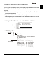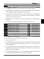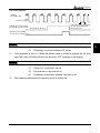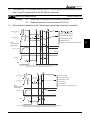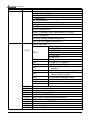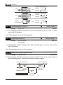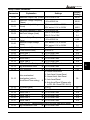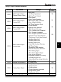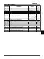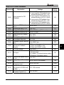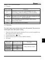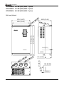
1
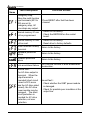
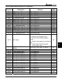
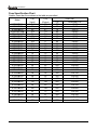
230V Series
0.75
37KW
1.0
50HP
460V Series
0.75
75KW
1.0
100HP
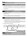
VFD-B Series
Preface
Thank you for choosing DELTA’s high-performance VFD-B Series. VFD-B Series are
manufactured by adopting high-quality components, material and incorporating the latest
microprocessor technology available.
Getting Started
This manual will be helpful in the installation, parameter setting, troubleshooting, and daily
maintenance of the AC motor drives. To guarantee safe operation of the equipment, read
the following safety guidelines before connecting power to the AC drives. Keep this
operating manual handy and distribute to all users for reference.
!
!
!
WARNING
Always read this manual thoroughly before using VFD-B series AC Motor Drives.
DANGER! AC input power must be disconnected before any maintenance. Do
not connect or disconnect wires and connectors while power is applied to the
circuit. Maintenance must be performed by qualified technicians.
!
CAUTION! There are highly sensitive MOS components on the printed circuit boards.
These components are especially sensitive to static electricity. To avoid damage to
these components, do not touch these components or the circuit boards with metal
objects or your bare hands.
!
DANGER! A charge may still remain in the DC-link capacitor with hazardous voltages
even if the power has been turned off. To avoid personal injury, please ensure that
power has turned off before operating AC drive and wait ten minutes for capacitors to
discharge to safe voltage levels.
!
CAUTION! Ground the VFD-B using the ground terminal. The grounding method
must comply with the laws of the country where the AC drive is to be installed. Refer to
Basic Wiring Diagram.
!
DANGER! The AC drive may be destroyed beyond repair if incorrect cables are
connected to the input/output terminals. Never connect the AC drive output terminals
U/T1, V/T2, and W/T3 directly to the AC main circuit power supply.
!
CAUTION! The final enclosures of the AC drive must comply with EN50178. (Live
parts shall be arranged in enclosures or located behind barriers that meet at least the
requirements of the Protective Type IP20. The top surface of the enclosures or barrier
that is easily accessible shall meet at least the requirements of the Protective Type
IP40). (VFD-B series corresponds with this regulation.)
CAUTION! Heat sink may heat up over 70oC (158oF), during the operation. Do not
touch the heat sink.
DELTA ELECTRONICS, INC. ALL RIGHTS RESERVED
VFD-B Series
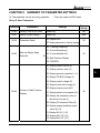
TABLE OF CONTENTS
CHAPTER 1
RECEIVING AND INSPECTIONS
1.1 Nameplate Information ....................................................................... 1 - 1
1.2 Model Explanation .............................................................................. 1 - 1
1.3 Serial Number Explanation................................................................. 1 - 2
CHAPTER 2
STORAGE AND INSTALLATION
2.1 Storage ............................................................................................... 2 - 1
2.2 Installation .......................................................................................... 2 - 2
CHAPTER 3
WIRING
3.1 Basic Wiring Diagram ......................................................................... 3 - 2
3.2 External Wiring ................................................................................... 3 - 6
3.3 Terminal Explanation .......................................................................... 3 - 7
3.4 Control Terminal Explanation.............................................................. 3 - 7
3.5 Main Circuit Wiring ............................................................................ 3 - 9
3.6 Wiring Notes ....................................................................................... 3-16
3.7 Motor Operation Precautions.............................................................. 3-17
CHAPTER 4
DIGITAL KEYPAD OPERATION
4.1 Description of the Digital Keypad VFD-PU01 ..................................... 4 - 2
4.2 Operation steps of the Digital Keypad VFD-PU01.............................. 4 - 4
DELTA ELECTRONICS, INC. ALL RIGHTS RESERVED
VFD-B Series
CHAPTER 5
DESCRIPTION OF PARAMETER SETTINGS
Group 0: User Parameters ....................................................................... 5 - 1
Group 1: Basic Parameters ...................................................................... 5 - 5
Group 2: Operating Method Parameters .................................................. 5 - 11
Group 3: Output Function Parameters ..................................................... 5-17
Group 4: Input Function Parameters ........................................................ 5-22
Group 5:Multi-step Speed and PLC (Process Logic Control) Parameter . 5-32
Group 6: Protection Parameters............................................................... 5-38
Group 7: Motor Parameters...................................................................... 5-44
Group 8: Special Parameters ................................................................... 5-47
Group 9: Communication Parameters ...................................................... 5-54
Group 10: PID Control Parameters .......................................................... 5-69
Group 11: Fan and Pump Control Parameters ......................................... 5-74
CHAPTER 6
MAINTENANCE AND INSPECTIONS
6.1 Periodic Inspection ............................................................................. 6 - 1
6.2 Periodic Maintenance ......................................................................... 6 - 1
CHAPTER 7
TROUBLESHOOTING AND FAULT INFORMATION ........... 7 - 1
CHAPTER 8
SUMMARY OF PARAMETER SETTINGS ............................ 8 - 1
APPENDIX A
SPECIFICATIONS ............................................................... A - 1
DELTA ELECTRONICS, INC. ALL RIGHTS RESERVED
VFD-B Series
APPENDIX B
ACCESSORIES
B.1 Non-fused Circuit Breaker and Fuse Specification Chart................... B - 1
B.2 Braking Resistors & Braking Units ..................................................... B - 3
B.3 AMD-EMI Filter Cross Reference....................................................... B - 7
B.4 PG Cards ........................................................................................... B-16
B.5 Remote Controller RC-01................................................................... B-22
B.6 Remote Panel Adapter ....................................................................... B-23
B.7 Zero Phase Reactor ........................................................................... B-24
APPENDIX C
DIMENSIONS....................................................................... C - 1
APPENDIX D
EC DECELERATION OF CONFORMITY............................. D - 1
DELTA ELECTRONICS, INC. ALL RIGHTS RESERVED
VFD-B Series
CHAPTER 1 RECEIVING AND INSPECTION
1
This VFD-B AC drive has gone through rigorous quality control tests at the factory before
shipment. After receiving the AC drive, please check for the following:
Receiving
Check to make sure that the package includes an AC drive, the User Manual, dust
covers and rubber bushings.
Inspect the unit to insure it was not damaged during shipment.
Make sure that the part number indicated on the nameplate corresponds with the part
number of your order.
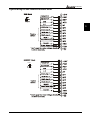
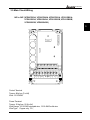
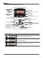
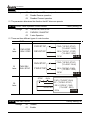
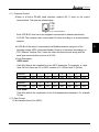
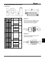
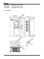
1.1 Nameplate Information: Example for 1HP/0.75kW 3-phase 230V AC drive
AC Drive Model
Input Spec.
Output Spec.
MODE
: VFD007B23A
INPUT
: 3PH 200-240V 50/60Hz 6.0A
OUTPUT
: 3PH 0-240V 5.0A 1.9kVA 1HP
Freq. Range : 0.1~400Hz
ENCLOSURE: TYPE 1
Output Frequency Range
Enclosure type
Serial Number & Bar Code
007B23A0T0220001
1.2 Model Explanation:
VFD 007 B 23 A
Series Name
Version Type
Input Voltage
21:Single phase 230V 23:Three phase 230V
43:Three phase 460V
B Series
Applicable motor capacity
007: 1 HP(0.7kW)
150: 20HP(15kW)
022: 3 HP(2.2kW)
220: 30 HP(22kW)
037: 5 HP(3.7kW)
300: 40HP(30kW)
055: 7.5HP(5.5kW) 370: 50 HP(37kW)
075: 10 HP(7.5kW) 450: 60HP(45kW)
110: 15 HP(11kW)
550: 75HP(55kW)
750: 100HP(75kW)
DELTA ELECTRONICS, INC. ALL RIGHTS RESERVED
1-1
VFD-B Series
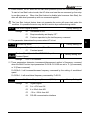
1.3 Series Number Explanation:
007B23A0
1
T 3 01
230V 3-phase 1HP(0.75kW)
Production number
Production week
Production year 2003
Production factory
(Taoyuan)
Model
If there is any nameplate information not corresponding to your purchase order or any
problem, please contact your distributor.
1-2
DELTA ELECTRONICS, INC. ALL RIGHTS RESERVED
VFD-B Series
CHAPTER 2 STORAGE AND INSTALLATION
2.1 Storage
The AC drive should be kept in the shipping carton before installation. In order to retain the
warranty coverage, the AC drive should be stored properly when it is not to be used for an
extended period of time.
Ambient Conditions:
Operation
Storage
Transportation
Pollution Degree
Air Temperature: -10oC to +40oC (14oF to 104oF) (UL & cUL);
+50oC (122oF) without dust cover.
Atmosphere pressure: 86 to 106 kPa
Installation Site Altitude: below 1000m
Vibration: Maximum 9.80 m/s2 (1G) at less than 20Hz
Maximum 5.88 m/s2 (0.6G) at 20Hz to 50Hz
Temperature: -20oC to +60oC (-4oF to 140oF)
Relative Humidity: Less than 90%, no condensation allowed
Atmosphere pressure: 86 to 106 kPa
Temperature: -20oC to +60oC (-4oF to 140oF)
Relative Humidity: Less than 90%, no condensation allowed
Atmosphere pressure: 86 to 106 kPa
Vibration: Maximum 9.80 m/s2 (1G) at less than 20Hz, Maximum 5.88
m/s2 (0.6G) at 20Hz to 50Hz
2: good for a factory type environment.
DELTA ELECTRONICS, INC. ALL RIGHTS RESERVED
2-1
2
VFD-B Series
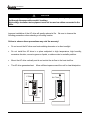
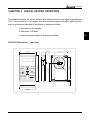
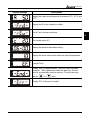
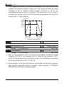
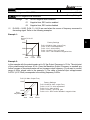
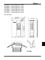
2.2 Installation
CAUTION
The control, power supply and motor leads must be laid separately. They must not be
fed through the same cable conduit / trunking.
High voltage insulation test equipment must not be used on cables connected to the
drive.
Improper installation of the AC drive will greatly reduce its life. Be sure to observe the
following precautions when selecting a mounting location.
Failure to observe these precautions may void the warranty!
Do not mount the AC drive near heat-radiating elements or in direct sunlight.
Do not install the AC drive in a place subjected to high temperature, high humidity,
excessive vibration, corrosive gases or liquids, or airborne dust or metallic particles.
Mount the AC drive vertically and do not restrict the air flow to the heat sink fins.
The AC drive generates heat. Allow sufficient space around the unit for heat dissipation.
120mm
Air Flow
50mm
FWD
REV
PROG
DATA
50mm
120mm
2-2
DELTA ELECTRONICS, INC. ALL RIGHTS RESERVED
VFD-B Series
CHAPTER 3 WIRING
DANGER
Hazardous Voltage
Before accessing the AC drive:
Disconnect all power to the AC drive.
Wait five minutes for DC bus capacitors discharge.
Any electrical or mechanical modification to this equipment without prior written
consent of Delta Electronics, Inc. will void all warranties and may result in a safety
hazard in addition to voiding the UL listing.
Short Circuit Withstand:
The rated voltage must be equal to or less than 240V (460V model is 480Volts) and the
current must be equal to or less than 5000A RMS. (the model of 40HP or above is 10000A
RMS)
General Wiring Information
Applicable Codes
All VFD-B AC drives except 015B21A, 015B23A and 075B23B are Underwriters
Laboratories, Inc. (UL) and Canadian Underwriters Laboratories (cUL) listed, and therefore
comply with the requirements of the National Electrical Code (NEC) and the Canadian
Electrical Code (CEC).
Installation intended to meet the UL and cUL requirements must follow the instructions
provided in “Wiring Notes” as a minimum standard. Follow all local codes that exceed UL
and cUL requirements. Refer to the technical data label affixed to the AC drive and the
motor nameplate for electrical data.
The "Line Fuse Specification" in Appendix B, lists the recommended fuse part number for
each B-Series part number. These fuses (or equivalent) must be used on all installations
where compliance with U.L. standards is a required.
DELTA ELECTRONICS, INC. ALL RIGHTS RESERVED
3-1
3
VFD-B Series
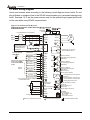
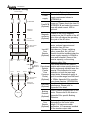
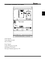
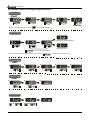
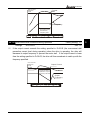
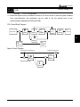
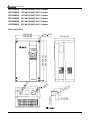
3.1 Basic Wiring Diagram
Users must connect wires according to the following circuit diagram shown below. Do not
plug a Modem or telephone line to the RS-485 communication port, permanent damage may
result. Terminals 1 & 2 are the power sources only for the optional copy keypad and should
not be used while using RS-485 communication.
Figure 1 for models of VFD-B Series
VFD007B21A/23A/43A, VFD015B21A/21B/23A/23B/43A
DC choke
VFD022B23B/43B
(optional)
Jumper
Fuse/NFB(None Fuse Breaker)
+1
R(L1)
S(L2)
T(L3)
E
R(L1)
S(L2)
T(L3)
SA
Recommended Circuit
when power supply
is turned OFF by a
fault output
Factory Default:
SINK Mode
ON
OFF
REV/STOP
Sw1
JOG
Source
Please refer to Figure 4
for wiring of SINK
mode and SOURCE
mode.
E.F.
Multi-step 1
Multi-step 2
Multi-step 3
Multi-step 4
RESET
Accel/Decel prohibit
Counter
Digital Signal Common
* Don't apply the mains voltage directly
to above terminals.
5K
1
E
RB
RA
RB
+24V
FWD
REV
JOG
EF
MI1
MI2
MI3
MI4
MI5
MI6
TRG
DCM
RC
MO1
MO2
Factory default:
Freq. Setting Indication
48V50mA
MO3
MCM
AFM
ACM
E
+10V
4~20mA
-10~+10V
E
DFM
Analog Signal Common
Main circuit (power) terminals
Master Frequency
0 to 10V 47K
ACI
AUI
ACM
DCM
Factory default:
Low-voltage Indication
48V50mA
Multi-function
Photocoulper Output
Analog Multi-function Output
Terminal
Factory default: Analog freq.
/ current meter 0~10VDC/2mA
Analog Signal common
Digital Frequency Output
Terminal
Factory default: 1:1
Duty=50%
Digital Signal Common
RS-485
Serial interface
1: EV 2: GND 3: SG4: SG+ 5:NC
6: for communication
E
Control circuit terminals
3-2
Please refer to “Control
Terminal Explanation”.
Factory default:
indicates during operation
48V50mA
AVI
2
IM
3~
W(T3)
Power supply
+10V 20mA
3
Motor
V(T2)
RC
MC
FWD/STOP
Sink
Factory
default
MC
B2
U(T1)
Shielded leads & Cable
DELTA ELECTRONICS, INC. ALL RIGHTS RESERVED
VFD-B Series
Figure 2 for models of VFD-B Series 3-15 HP
VFD022B21A, VFD037B23A/43A, VFD055B23A/43A, VFD075B23A/43A, VFD110B23A/43A
* Three phase input power may apply to single phase drives.
* For the single phase application, the AC input line can
be connected to any two of the three input terminals R,S,T
Fuse/NFB(None Fuse Breaker)
T(L3)
Factory Default:
SINK Mode
MC
REV/STOP
Sw1
JOG
Source
Please refer to Figure 4
for wiring of SINK
mode and SOURCE
mode.
E.F.
Multi-step 1
Multi-step 2
Multi-step 3
Multi-step 4
RESET
Accel/Decel prohibit
Counter
Digital Signal Common
* Don't apply the mains voltage directly
to above terminals.
Motor
IM
3~
RA
RB
+24V
FWD
REV
JOG
EF
MI1
MI2
MI3
MI4
MI5
MI6
TRG
DCM
E
+10V
AVI
2
1
W(T3)
RB
Power supply
+10V 20mA
3
5K
V(T2)
RC
FWD/STOP
Sink
Factory
default
MC
ON
B2 -(minus sign)
U(T1)
E
SA
OFF
BR
BR
+1
R(L1)
S(L2)
T(L3)
E
R(L1)
S(L2)
Recommended Circuit
when power supply
is turned OFF by a
fault output
VFDB
DC chock
(optional)
Jumper
4~20mA
-10~+10V
Analog Signal Common
Main circuit (power) terminals
DELTA ELECTRONICS, INC. ALL RIGHTS RESERVED
RC
MO1
Factory default:
indicates during operation
48V50mA
MO2
Factory default:
Freq. Setting Indication
48V50mA
MO3
MCM
AFM
ACM
E
DFM
Master Frequency
0 to 10V 47K
ACI
AUI
ACM
DCM
6
E
Control circuit terminals
3-3
Please refer to “Control
Terminal Explanation”.
Factory default:
Low-voltage Indication
48V50mA
Multi-function
Photocoulper Output
Analog Multi-function Output
Terminal
Factory default: Analog freq.
/ current meter 0~10VDC/2mA
Analog Signal common
Digital Frequency Output
Terminal
Factory default: 1:1
Duty=50%
Digital Signal Common
RS-485
1 Serial interface
1: EV 2: GND 3: SG4: SG+ 5:NC
6: for communication
Shielded leads & Cable
3
VFD-B Series
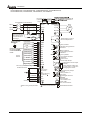
Figure 3 for models of VFD-B Series 20 HP and above
VFD150B23A/43A, VFD185B23A/43A, VFD220B23A/43A, VFD300B23A/43A,
VFD370B23A/43A, VFD450B43A, VFD550B43A, VFD750B43A
DC chock
(optional)
Fuse/NFB(None Fuse Breaker)
+1
R(L1)
S(L2)
T(L3)
E
R(L1)
S(L2)
T(L3)
SA
Recommended Circuit
when power supply
is turned OFF by a
fault output
Factory Default:
SINK Mode
ON
MC
REV/STOP
Sw1
JOG
Source
Please refer to Figure 4
for wiring of SINK
mode and SOURCE
mode.
E.F.
Multi-step 1
Multi-step 2
Multi-step 3
Multi-step 4
RESET
Accel/Decel prohibit
Counter
Digital Signal Common
* Don't apply the mains voltage directly
to above terminals.
1
4~20mA
-10~+10V
Analog Signal Common
Main circuit (power) terminals
IM
3~
V(T2)
W(T3)
E
RB
RA
RB
+24V
FWD
REV
JOG
EF
MI1
MI2
MI3
MI4
MI5
MI6
TRG
DCM
Please refer to “Control
Terminal Explanation”.
RC
MO1
Factory default:
indicates during operation
48V50mA
MO2
Factory default:
Freq. Setting Indication
48V50mA
MO3
MCM
AFM
ACM
E
+10V
AVI
2
Motor
U(T1)
Power supply
+10V 20mA
3
5K
-(minus sign)
RC
FWD/STOP
Sink
Factory
default
MC
OFF
VFDB
Jumper
E
DFM
Master Frequency
0 to 10V 47K
ACI
AUI
ACM
DCM
6
E
Control circuit terminals
3-4
Factory default:
Low-voltage Indication
48V50mA
Multi-function
Photocoulper Output
Analog Multi-function Output
Terminal
Factory default: Analog freq.
/ current meter 0~10VDC/2mA
Analog Signal common
Digital Frequency Output
Terminal
Factory default: 1:1
Duty=50%
Digital Signal Common
RS-485
1 Serial interface
1: EV 2: GND 3: SG4: SG+ 5:NC
6: for communication
Shielded leads & Cable
DELTA ELECTRONICS, INC. ALL RIGHTS RESERVED
VFD-B Series
Figure 4 Wiring for SINK mode and SOURCE mode
3
Sink
Sw1
Source
DELTA ELECTRONICS, INC. ALL RIGHTS RESERVED
3-5
VFD-B Series
3.2 External Wiring
Power Supply
Items
Explanations
Please follow the specific power
Power
supply requirement shown in
supply
APPENDIX-A.
There may be inrush current during
Fuse/NFB power up. Please check the chart of
APPENDIX B and select the correct
(Optional) fuse with rated current. NFB is
optional.
FUSE/NFB
Magnetic
contactor
Input AC
Line Reactor
Please do not use a Magnetic
Magnetic
contactor as the I/O switch of the AC
contactor
drive, this will reduce the operating
(Optional)
life cycle of the AC drive.
Zero-phase
Reactor
Input AC
Line
Reactor
(Optional)
EMI Filter
R/L1
S/L2
T/L3
+1
+2/B1
B2
U/T1
V/T2
DC
Choke
Braking
Resistor
W/T3
Zero-phase
Reactor
Output AC
Line Reactor
Motor
Zero-phase
Reactor
(Ferrite
Core
Common
Choke)
(Optional)
EMI filter
(Optional)
In order to improve the input power
factor, reduces harmonics and
protection from AC line
disturbances. (Surge, switching
spike, power flick, etc.) AC line
reactor should be installed when the
power supply capacity is 500kVA or
more and exceeds 6 times of the
inverter capacity, or the wiring
distance within 10m.
Zero phase reactors are used to
reduce radio noise specify when the
audio equipments installed near the
inverter. Good effective for noise
reduction on both the input and
output sides. Attenuation quality is
good in a wide range from AM band
to 10Mhz. Appendix B for specifies
zero phase reactors. (RF220X00A)
To reduce the electromagnetic
interference. Please refer to
Appendix B for detail.
Used to reduce stopping time of the
Braking
motor. Please refer to the chart on
Resistor
Appendix B for specific Braking
(Optional)
Resistors.
Output AC
Line
Reactor
(Optional)
3-6
Motor surge voltage amplitudes
depending on the motor cable
length. For long motor cable
application, it is necessary installed
on the inverter output side.
DELTA ELECTRONICS, INC. ALL RIGHTS RESERVED
VFD-B Series
3.3 Terminal Explanations
Terminal Symbol
Explanation of Terminal Function
R/L1, S/L2, T/L3
AC line input terminals
U/T1, V/T2, W/T3
AC drive output terminals motor connections
+1,+2
Connections for DC Link Reactor (optional)
+2/B1~B2
Connections for Braking Resistor (optional)
+2 ~ -(minus sign)
+2/B1~ -(minus sign)
Connections for External Braking Unit (VFDB series)
Earth Ground
3.4 Control Terminals Explanations
Terminal Symbols
Terminal Functions
FWD
Forward-Stop command
REV
Reverse-Stop command
JOG
Jog command
EF
External fault
TRG
External counter input
MI1
Multi-function Input 1
MI2
Multi-function Input 2
MI3
Multi-function Input 3
MI4
Multi-function Input 4
MI5
Multi-function Input 5
MI6
Multi-function Input 6
Factory Settings
Refer to Pr.04-04 to Pr.04-09
Multi-function Input Terminals
Digital Frequency Meter
(Open Collector Output)
Factory setting 1:1
(Maximum 48VDC, 50mA)
+24V
DC Voltage Source
(+24V, 20mA), used for source mode.
DCM
Digital Signal Common
Used as common for digital inputs
and used for sink mode.
DFM
DELTA ELECTRONICS, INC. ALL RIGHTS RESERVED
3-7
3
VFD-B Series
Terminal Symbols
RB
Terminal Functions
Multi-function Relay output
(N.O.) a
Multi-function Relay output
(N.C.) b
RC
Multi-function Relay common
RA
Factory Settings
Resistor Load
5A(N.O.)/3A(N.C.) 240VAC
5A(N.O.)/3A(N.C.) 24VDC
Inductive Load
1.5A(N.O.)/0.5A(N.C.) 240VAC
1.5A(N.O.)/0.5A(N.C.) 24VDC
Refer to Pr.03-01 to Pr.03-03
Multi-function output 1
(Photocoupler)
Multi-function output 2
(Photocoupler)
Multi-function output 3
(Photocoupler)
Maximum 48VDC, 50mA
Refer to Pr.03-01 to Pr.03-03
MCM
Multi-function output common
Maximum 48VDC, 50mA
+10V
Potentiometer output power
source
+10V 20mA
AVI
Analog voltage Input
0 to +10V
ACI
Analog current Input
4 to 20mA
AUI
Auxiliary analog voltage input
-10 to +10V
AFM
Analog output meter
0 to 10V, 2mA
ACM
Analog control signal
(common)
MO1
MO2
MO3
* Control signal wiring size: 18 AWG (0.75 mm2).
3-8
DELTA ELECTRONICS, INC. ALL RIGHTS RESERVED
VFD-B Series
3.5 Main Circuit Wiring
1HP to 3HP (VFD007B23A, VFD007B43A, VFD007B21A, VFD015B21A,
VFD015B23A, VFD015B43A, VFD015B21B, VFD015B23B,
VFD022B23B, VFD022B43B)
3
S
T
R
/L1 /L2 /L3
+1
+2
/B1
B2
V
W
U
/T1 / T2 /T3
Control Terminal
Torque: 4Kgf-cm (3 in-lbf)
Wire: 12-24 AWG
Power Terminal
Torque: 18 kgf-cm (15.6 in-lbf)
Wire Gauge: 10-18 AWG stranded wire, 12-18 AWG solid wire
Wire Type: Copper only, 75°C
DELTA ELECTRONICS, INC. ALL RIGHTS RESERVED
3-9
VFD-B Series
3HP to 5HP (VFD022B21A, VFD037B23A, VFD037B43A)
+1 +2 B1 -
B2
U/T1 V/T2 W/T3
Screw Torque :
18Kgf-cm
Wire Gauge :
18~10AWG
R/L1 S/L2 T/L3
Control Terminal
Torque: 4Kgf-cm (3 in-lbf)
Wire: 12-24 AWG
Power Terminal
]Torque: 18 kgf-cm (15.6 in-lbf)
Wire Gauge: 10-18 AWG
Wire Type: Stranded copper only, 75°C
3-10
DELTA ELECTRONICS, INC. ALL RIGHTS RESERVED
VFD-B Series
7.5 HP to 15 HP (VFD055B23A, VFD055B43A, VFD075B23A, VFD075B43A,
VFD110B23A, VFD110B43A)
3
POWER
IM
3
MOTOR
Control Terminal
Torque: 4Kgf-cm (3 in-lbf)
Wire: 12-24 AWG
Power Terminal
Torque: 30Kgf-cm (26 in-lbf)
Wire: 8-12 AWG
Wire Type: Stranded Copper only, 75°C
NOTE: If wiring of the terminal utilizes the wire with a 6AWG-diameter, it is thus necessary
to use the Recognized Ring Terminal to conduct a proper wiring.
DELTA ELECTRONICS, INC. ALL RIGHTS RESERVED
3-11
VFD-B Series
20 HP to 30 HP (VFD150B23A, VFD150B43A, VFD185B23A, VFD185B43A,
VFD220B23A, VFD220B43A)
R/L1 S/L2 T/L3 +1
POWER
+2
DC (+)
-
DC ( - )
V/T2 W/T3
IM
3
MOTOR
Control Terminal
Torque: 4Kgf-cm (3 in-lbf)
Wire: 12-24 AWG
Power Terminal
Torque: 30Kgf-cm (26 in-lbf)
Wire: 2-8 AWG
Wire Type: Stranded Copper only, 75°C
NOTE: If wiring of the terminal utilizes the wire with a 1AWG-diameter, it is thus necessary
to use the Recognized Ring Terminal to conduct a proper wiring.
3-12
DELTA ELECTRONICS, INC. ALL RIGHTS RESERVED
VFD-B Series
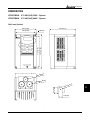
40 HP to 50 HP
230V (VFD300B23A, VFD370B23A)
POWER
3
ALARM
CHARGE
R/L1 S/L2 T/L3
POWER
+1
+2
Screw Torque:
200kgf-cm (173in-lbf)
Control Terminal
Torque: 4Kgf-cm (3 in-lbf)
Wire: 12-24 AWG
Power Terminal
Torque: 200kgf-cm (173 in-lbf)
Wire Gauge: 2/0 - 3/0 AWG
Wire Type: Stranded copper only, 75°C
DELTA ELECTRONICS, INC. ALL RIGHTS RESERVED
3-13
U/T1 V/T2 W/T3
IM
3
MOTOR
VFD-B Series
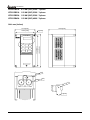
40 HP to 60 HP 460V (VFD300B43A, VFD370B43A, VFD450B43A)
POWER
ALARM
CHARGE
R/L1 S/L2 T/L3
+1
+2
-
U/T1 V/T2 2/T3
IM
3
POWER
MOTOR
Control Terminal
Torque: 4Kgf-cm (3 in-lbf)
Wire: 12-24 AWG
Power Terminal
Torque: 58.7kgf-cm (50.9 in-lbf) max.
Wire Gauge: 2-4AWG
Wire Type: Stranded copper only, 75°C
3-14
DELTA ELECTRONICS, INC. ALL RIGHTS RESERVED
VFD-B Series
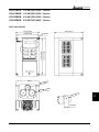
75-100 HP 460V (VFD550B43A, VFD750B43A)
3
R/L1 S/L2 T/L3
+1
POWER
+2
Screw Torque:
200kgf-cm ( 173in- lbf)
Control Terminal
Torque: 4Kgf-cm (3 in-lbf)
Wire: 12-24 AWG
Power Terminal
Torque: 200 kgf-cm (173 in-lbf)
Wire Gauge: 2/0-3/0 AWG
Wire Type: Stranded copper only, 75°C
DELTA ELECTRONICS, INC. ALL RIGHTS RESERVED
3-15
U/T1 V/T2 W/T3
IM
3
MOTOR
VFD-B Series
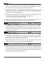
3.6 Wiring Notes: PLEASE READ PRIOR TO INSTALLATION.
1. There are corresponding ring terminals which will be included with each unit (20-30HP),
and please use the proper crimping tool by KST INC. P/N: KST-HDC38A for securing
the conductor.
2.
3.
CAUTION: Do not connect the AC power to the U/T1, V/T2, W/T3 terminals, as it
will damage the AC drive.
!
!
WARNING: Ensure all screws are tightened to the proper torque rating.
4. During installation, follow all local electrical, construction, and safety codes for the
country the drive is to be installed in.
5. Ensure that the appropriate protective devices (circuit breaker or fuses) are connected
between the power supply and AC drive.
6. Make sure that the leads are connected correctly and the AC drive is properly grounded.
(Ground resistance should not exceed 0.1Ω .)
7. Use ground leads that comply with AWG/MCM standards and keep them as short as
possible.
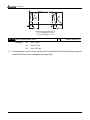
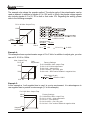
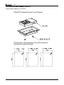
8. Multiple VFD-B units can be installed in one location. All the units should be grounded
directly to a common ground terminal. The VFD-B ground terminals may also be
connected in parallel, as shown in the figure below.
Ensure there are no ground
loops.
Forward
running
9. When the AC drive output terminals U/T1, V/T2, and W/T3 are connected to the motor
terminals U/T1, V/T2, and W/T3, respectively, the motor will rotate counterclockwise (as
viewed from the shaft ends of the motor) when a forward operation command is received.
To reverse the direction of motor rotation, switch over any of the two motor leads.
3-16
DELTA ELECTRONICS, INC. ALL RIGHTS RESERVED
VFD-B Series
10. Make sure that the power source is capable of supplying the correct voltage and
required current to the AC drive.
11. Do not attach or remove wiring when power is applied to the AC drive.
12. Do not monitor the signals on the circuit board while the AC drive is in operation.
13. For the single-phase rated AC drives, the AC power can be connected to any two of the
three input terminals R/L1, S/L2, T/L3. Note: This drive is not intended for the use
with single-phase motors.
14. Route the power and control wires separately, or at 90°angle to each other.
15. If a filter is required for reducing EMI (Electro Magnetic Interference), install it as close
as possible to AC drive.
EMI can also be reduced by lowering the Carrier Frequency.
16. If the AC drive is installed in the place where a load reactor is needed, install the filter
close to U/T1, V/T2, W/T3, side of AC drive. Do not use a Capacitor or L-C Filter
(Inductance-Capacitance) or R-C Filter (Resistance-Capacitance), unless approved by
Delta.
17. When using a GFCI (Ground Fault Circuit Interrupt), select current sensor with sensitivity
of 200mA, and not less than 0.1-second detection to avoid nuisance tripping.
3.7 Motor Operation Precautions
1. When using the AC drive to operate a standard 3-phase induction motor, notice that the
energy loss is greater than for an inverter duty motor.
2. Avoid running a standard induction motor at low speed. Under these conditions, the
motor temperature may rise above the motor rating due to limited airflow produced by
the motor’s fan.
3. When the standard motor operates at low speed, the output load must be decreased.
4. If 100% output torque is desired at low speed, it may be necessary to use a special
“inverter-duty” rated motor.
DELTA ELECTRONICS, INC. ALL RIGHTS RESERVED
3-17
3
VFD-B Series
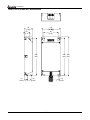
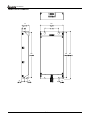
CHAPTER 4
DIGITAL KEYPAD OPERATION
This chapter describes the various controls and indicators found on the digital keypad/display
PU01. The information in this chapter should be read and understood before performing the
start–up procedures described in the chapter of parameter settings.
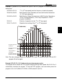
ª Description of the Keypad
ª Description of Display
4
ª Keypad Operation Modes & Programming Steps
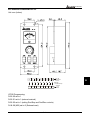
mm (inch)
110.0 [4.33]
40
.0
MODE
58
[1 .
]
PROG
DATA
STOP
6.5 [0.26]
RUN
M4* 0.7(2X)
?
JOG
44.0 [1.73]
97.0 [3.82]
19.0 [0.75]
73.0 [2.87]
77.0 [3.03]
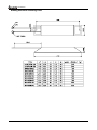
VFD-PU01 Dimensions:
DELTA ELECTRONICS, INC. ALL RIGHTS RESERVED
4-1
VFD-B Series
4.1 Description of the Digital Keypad VFD-PU01
F
H
U
LED Display
Display frequency, current, voltage
and error, etc.
VFD-PU01
Part Number
Status Display
Display the driver's current status
JOG
By pressing JOG key.
Initiates jog operation.
MODE
Changes between different
JOG
display mode.
Left key
moves cursor to the left
UP and DOWN Key
Sets the parameter
number and changes the
numerical data, such as
Master Frequency.
STOP/RESET
RUN
STOP
RESET
Display Message
RUN key
Descriptions
Display the AC drive Master Frequency.
Display the actual operation frequency present at terminals
U/T1, V/T2, and W/T3.
User defined unit, where (U = F x Pr.00-05)
4-2
DELTA ELECTRONICS, INC. ALL RIGHTS RESERVED
VFD-B Series
Display Message
Descriptions
Display the output current present at terminals U/T1, V/T2, and
W/T3.
Display the AC drive forward run status.
The AC drive reverse run status.
4
The counter value (C).
Display the specified parameter setting.
Display the actual value stored within the specified parameter.
External Fault.
Display “End” for approximately 1 second if input has been
accepted. After a parameter value has been set, the new
value is automatically stored in memory. To modify an entry,
use the
or
keys.
Display “Err”, if the input is invalid.
DELTA ELECTRONICS, INC. ALL RIGHTS RESERVED
4-3
VFD-B Series
4.2 Operation steps of the Digital Keypad VFD-PU01
Selecting mode
START
F
F
F
H
U
F
H
H
H
U
U
U
MODE
MODE
F
H
U
MODE
MODE
MODE
GO START
Note:In the selection mode, press
to set the parameters.
Setting parameters
F
H
U
F
H
U
F
H
U
Success to set parameter.
F
H
U
F
H
U
Input data error
MODE
move to previous display
NOTE:In the parameter setting mode, you can press
MODE
to return the selecting mode.
To shift data
START
F
F
F
F
F
F
H
U
F
H
U
H
U
H
U
F
H
U
H
U
F
H
U
To modify data
F
START
H
U
H
U
H
U
Setting direction
F
H
U
or
or
4-4
DELTA ELECTRONICS, INC. ALL RIGHTS RESERVED
VFD-B Series
CHAPTER 5 DESCRIPTION OF PARAMETER SETTINGS
Group 0: User Parameters
a: This parameter can be set during operation.
00 - 00 Identity Code of AC Drive
Factory setting: ##
Factory Setting
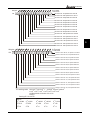
00 - 01 Rated Current Display of the AC drive
Settings
Factory setting:
None
#.#
Unit: 0.1 A
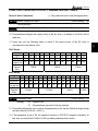
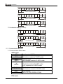
This parameter displays the rated current of the AC drive. It is based on Pr.00-00, and is
read-only.
Users can use the following table to check if the rated current of the AC drive is
corresponds to the identity code.
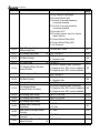
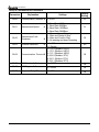
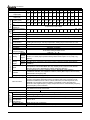
230V Series
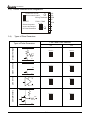
KW
0.75
HP
1.0
Pr.00-00
04
Rated
5.0
current (A)
Max.
Carried
Freq.
1.5
2.0
06
2.2
3.0
08
3.7
5.0
10
5.5
7.5
12
7.5
10
14
11
15
16
15
20
18
18.5
25
20
22
30
22
30
40
24
37
50
26
7.0
11
17
25
33
49
65
75
90
120
146
15KHz
15 KHz
9 KHz
460V Series
KW
HP
Pr.00-00
Rated
Current (A)
Max.
Carried
Freq.
0.75 1.5
1.0 2.0
05 07
2.2
3.0
09
3.7
5.0
11
5.5
7.5
13
7.5
10
15
11
15
17
15 18.5 22
20 25 30
19 21 23
30
40
25
37
50
27
45
60
29
55
75
31
2.7
5.5
8.5
13
18
24
32
60
73
91
110 150
4.2
15 KHz
15 KHz
38
45
9 KHz
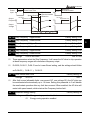
00 - 02 Parameter Reset
Settings
75
100
33
6 KHz
Factory Setting:
08
Keypad Lock
10
All parameters are reset to factory settings
00
This setting allows the user to return all parameters to the factory default settings except
the fault records (Pr.06-08 ~ Pr06-11).
If this parameter is set to 08, the operation function of VFD-PU01 keypad is disabled. At
this time, you should set Pr.00-02 to 00 to disable parameter lock function.
DELTA ELECTRONICS, INC. ALL RIGHTS RESERVED
5-1
5
VFD-B Series
a
00 - 03 Start-up Display Page Selection
Settings
Factory Setting: 00
00
Display the Master Frequency (F)
01
Display the actual operation frequency (H)
02
Display the content of user-defined unit (U)
03
Multifunction display, [default setting: output current (A)]
04
FWD/REV command
This setting determines the display mode after power is applied to the drive.
a
00 - 04 Content of Multi Function Display
Settings
Factory Setting: 00
00
Display the output current (A)
01
Display the counter value (C)
02
Display the content of PLC time (1.tt)
03
Display the DC BUS voltage (U)
04
Display the output voltage (E)
05
Display the power factor angle (n.)
06
Display the output power (P), unit: kW
07
Display actual motor speed (enable during vector control or Pulse
Generator feedback control) (HU)
08
Display the estimative value of the ration of torque (t)
09
Display PG numbers/10ms (G)
10
Display analog feedback signal value (b) (%)
11
Display AVI (U1.) (%)
12
Display ACI (U2.) (%)
13
Display AUI (U3.) (%)
This parameter determines the content for Multi function Display. User also can view
other information by pressing the “LEFT” key on the VFD-PU01 when the display page is
at Multi function Display.
The 100% of settings 11-13 is +10V or 20mA.
a
00 - 05 User Defined Coefficient K
Settings
Factory Setting: 1.00
0.01 to d 160.00
Unit: 0.01
The coefficient K determines the multiplying factor for the user-defined unit.
The display value is calculated as follows:
U (user-defined unit) = Frequency Command x K (Pr.00-05)
H (actual output) = (actual output frequency) x K (Pr.00-05)
5-2
DELTA ELECTRONICS, INC. ALL RIGHTS RESERVED
VFD-B Series
The display window is only capable of showing five digits, yet you could use Pr.00-05 to
create larger numbers. The display windows use decimal points to signify numbers up
to seven digits as illustrated below:
Display
Number Represented
99999
The absence of a decimal point indicates a five-digit integer.
9999.9
A signal decimal point between the middle and the right-most numbers is a true
decimal point. For example, the number 1234.5 would be displayed as “1234.5”.
A single decimal point after the right-most number is not a true decimal point;
99999. instead it indicates that a zero follows the right-most number. For example, the
number 123450~123459 would be displayed as “12345.”
Two decimal points (one between the middle and the right-most numbers, and one
after the right-most number) are not true decimal points; instead they indicate that
9999.9.
two zeros follow the right-most number. For example, the number
3456700~3456799 would be displayed as “3456.7.”.
00 - 06 Software Version
Settings
Factory Setting: ###
None
The software version is read-only.
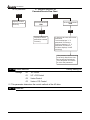
00 - 07 Password Decode
Factory Setting: 00
Display
00-02 (times of wrong password)
Settings
1 to 65535
Unit: 1
Function of this parameter is to decode the password that is to be input into Pr.00-08.
Input the correct password here so as to revise the parameters; the trials are limit to 3
times only. If the entered passwords are wrong consecutively, a blinking “codE” will
show up to caution the users to restart the AC drive in order to key in the correct
password again.
00 - 08 Password Input
Settings
Factory Setting: 00
1 to 65535
Unit: 1
To cancel the parameter lock, setting the parameter as 0. To lock all parameters, setting
a value other than 0 in the parameter as a password. To change the one of the
parameter settings of this AC drive, one must enter the correct password in Pr.00-07 to
activate this function. Be sure to keep the password in mind for later use.
Display states:
DELTA ELECTRONICS, INC. ALL RIGHTS RESERVED
5-3
5
VFD-B Series
00: no password
01: password has been set
Password Decode Flow Chart
00-08
00-07
Displays 0 when
password entered
correctly.
Incorrect Password
END
Correct Password
END
00-07
00-08
Displays 0 when
password entered
correctly.
3 chances to enter the correct
password.
1st time displays "1" if
password is incorrect.
2nd time displays "2", if
password is incorrect.
3rd time displays "codE
(blinking)
If the password was entered
incorrectly after three tries,
the keypad will be locked.
Turn the power OFF/ON to
re-enter the password.
00 - 09 Control methods
Settings
Factory Setting: 00
00
V/F control
01
V/F + PG Control
02
Vector Control
03
Vector + PG Control
This parameter determines the control methods of the AC drive.
00 - 10 Reserved
5-4
DELTA ELECTRONICS, INC. ALL RIGHTS RESERVED
VFD-B Series
Group 1: Basic Parameters
01 - 00 Maximum Output Frequency
Settings
(Fmax)
50.00 to 400.00 Hz
Factory Setting: 60.00
Unit: 0.01Hz
This parameter determines the AC drive’s Maximum Output Frequency. All the AC drive
analog inputs (0 to +10V, 4 to 20mA, -10V to +10V) are scaled to correspond to the output
frequency range.
01 - 01 Maximum Voltage Frequency (Fbase)
Settings
0.10 to 400.00Hz
Factory Setting: 60.00
Unit: 0.01Hz
This value should be set according to rated frequency of the motor as indicated on the
motor nameplate. Maximum Voltage Frequency determines the volts per hertz ratio. For
example, if the drive is rated for 460 VAC output and the Maximum Voltage Frequency is
set to 60Hz, the drive will maintain a constant ratio of 7.66 V/Hz (460V/60Hz=7.66V/Hz).
This parameter value must be equal to or greater than the Mid-Point Frequency
(Pr.01-03).
01 - 02 Maximum Output Voltage (Vmax)
Settings
Unit: 0.1
230V series
0.1 to 255.0V
Factory Setting: 220.0
460V series
0.1 to 510.0V
Factory Setting: 440.0
This parameter determines the Maximum Output Voltage of the AC drive. The Maximum
Output Voltage setting must be smaller than or equal to the rated voltage of the motor as
indicated on the motor nameplate. This parameter value must be equal to or greater than
the Mid-Point Voltage (Pr.01-04).
01 - 03 Mid-Point Frequency (Fmid)
Settings
Factory Setting:
0.10 to 400.00Hz
0.50
Unit: 0.01Hz
This parameter sets the Mid-Point Frequency of the V/F curve. With this setting, the V/F
ratio between Minimum Frequency and Mid-Point frequency can be determined. This
parameter must be equal to or greater than Minimum Output Frequency (Pr.01-05) and
equal to or less than Maximum Voltage Frequency (Pr.01-01).
01 - 04 Mid-Point Voltage (Vmid)
Settings
Unit: 0.1
230V series
0.1 to 255.0V
Factory setting: 1. 7V
460V series
0.1 to 510.0V
Factory setting: 3.4V
DELTA ELECTRONICS, INC. ALL RIGHTS RESERVED
5-5
5
VFD-B Series
This parameter sets the Mid-Point Voltage of any V/F curve. With this setting, the V/F
ratio between Minimum Frequency and Mid-Point Frequency can be determined. This
parameter must be equal to or greater than Minimum Output Voltage (Pr.01-06) and
equal to or less than Maximum Output Voltage (Pr.01-02). However, this parameter is
ineffective when Pr.11-00 is set to 1 to 4.
01 - 05 Minimum Output Frequency (Fmin)
Settings
Factory Setting: 0.50
0.10 to 400.00Hz
Unit: 0.01Hz
This parameter sets the Minimum Output Frequency of the AC drive.
must be equal to or less than Mid-Point Frequency (Pr.01-03).
This parameter
The settings of 01-03, 01-04, 01-06 are invalid in Vector Control mode.
01 - 06 Minimum Output Voltage (Vmin)
Settings
Unit: 0.1
230V series
0.1 to 255.0V
Factory setting: 1. 7V
460V series
0.1 to 510.0V
Factory setting: 3.4V
This parameter sets the Minimum Output Voltage of the AC drive. This parameter must
be equal to or less than Mid-Point Voltage (Pr.01-04).
The settings of Pr.01-01 to Pr.01-06 have to meet the agreement that Pr.01-02 ≥
Pr.01-04 ≥ Pr.01-06 and Pr.01-01 ≥ Pr.01-03 ≥ Pr.01-05.
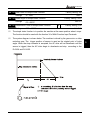
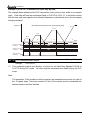
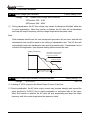
01 - 07 Upper Bound of Output Frequency
Settings
Factory Setting: 100
1 to 120%
Unit: 1%
This parameter must be equal to or greater than the Lower Bound of Output Frequency
(Pr.01-08). The Maximum Output Frequency (Pr.01-00) is regarded as 100%.
Upper Bound of Output Frequency value = (Pr.01-00 x Pr.01-07)/100
01-08
Lower Bound
Voltage Output Frequency
01-07
Upper Bound
Output Frequency
01-02
Maximum
Output
Voltage
01-04
Mid-point
Voltage
Output Frequency
01-06
setting limit
Minimum
Output
Voltage
01-01
01-00
01-05
01-03
Minimum Mid-point Maximum Voltage Maximum
Output
Freq.
Output
Frequency
Freq.
(Base Frequency) Frequency
V/F Curve
5-6
DELTA ELECTRONICS, INC. ALL RIGHTS RESERVED
VFD-B Series
01 - 08 Lower Bound of Output Frequency
Settings
Factory Setting: 00
00 to 100%
Unit: 1%
The Upper/Lower Bound is to prevent operation error and machine damage.
If the Upper Bound of Output Frequency is 50Hz and the Maximum Output Frequency is
60Hz, the Maximum Output Frequency will be limited to 50Hz.
If the Lower Bound of Output Frequency is 10Hz, and the Minimum Output Frequency
(Pr.01-05) is set at 1.0Hz, then any Command Frequency between 1.0-10Hz will
generate a 10Hz output from the drive.
This parameter must be equal to or less than the Upper Bound of Output Frequency
(Pr.01-07).
The Lower Bound of Output Frequency value = (Pr.01-00 x Pr.01-08) /100
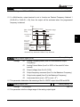
01 - 09 Acceleration Time 1 (Taccel 1)
a
Factory Setting: 10.0
01 - 10 Deceleration Time 1 (Tdecel 1)
a
Factory Setting: 10.0
01 - 11 Acceleration Time 2 (Taccel 2)
a
Factory Setting: 10.0
01 - 12 Deceleration Time 2 (Tdecel 2)
a
Factory Setting: 10.0
01 - 18 Acceleration Time 3 (Taccel 3)
a
Factory Setting: 10.0
01 - 19 Deceleration Time 3 (Tdecel 3)
a
Factory Setting: 10.0
01 - 20 Acceleration Time 4 (Taccel 4)
a
Factory Setting: 10.0
01 - 21 Deceleration Time 4 (Tdecel 4)
a
Factory Setting: 10.0
Settings
0.01 to 3600.0 sec
Unit: 0.1/0.01sec
♦ Factory setting 60sec is for the models of 30 HP and above.
Unit can be set by Pr.01-23.
The Acceleration Time is used to determine the time required for the AC drive to ramp
from 0 Hz to its Maximum Output Frequency (Pr.01-00). The rate is linear unless
S-Curve is “Enabled.”
The Deceleration Time is used to determine the time required for the AC drive to
decelerate from the Maximum Output Frequency (Pr.01-00) down to 0 Hz. The rate is
linear unless S-Curve is “Enabled.”
The Acceleration/Deceleration Time 1, 2, 3, 4 is switched according to the Multi-Function
Input Terminals Setting. See Pr.04-04 to Pr.04-09 for more details.
DELTA ELECTRONICS, INC. ALL RIGHTS RESERVED
5-7
5
VFD-B Series
In the diagram shown below, the Acceleration/Deceleration Time of the AC drive is time
between 0 Hz to Maximum Output Frequency (Pr.01-00). Suppose the Maximum Output
Frequency is 60 Hz, Minimum Output Frequency (Pr.01-05) is 1.0 Hz, and
Acceleration/Deceleration Time is 10 seconds. The actual time for the AC drive to
accelerate from start-up to 60 Hz is 9.83 seconds and the deceleration time is also 9.83
seconds. ((60-1) x 10/60=9.83secs).
Frequency
01-00
Max.
Output
Freq.
Setting
running
Freq.
Decel Time
Accel
Time
Time
01-09 01-11
01-10 01-12
01-18 01-20
01-19 01-21
Accel/Decel Time Definition
01 - 13 Jog Acceleration Time
Settings
a
0.1 to 3600.0 sec
Unit: 0.1sec
01 - 22 Jog Deceleration Time
Settings
01 - 14
a
Factory Setting: 1.0
a
Unit: 0.1sec
Factory Setting: 6.00
0.1 to 3600.0 sec
Jog Frequency
Settings
Factory Setting: 1.0
0.10 to 400.00Hz
Unit: 0.01Hz
When the Jog command is “ON”, the AC drive will accelerate from Minimum Output
Frequency (Pr.01-05) to Jog Frequency (Pr.01-14). When the Jog command is “OFF”,
the AC drive will decelerate from Jog Frequency to zero. The Accel/Decel time is decided
by the Jog Accel/Decel time (Pr.01-13, Pr01-22).
During operation, the AC drive cannot perform Jog command. And during Jog operation,
other operation commands cannot be accepted, except command of FORWARD,
REVERSE and STOP keys on the digital keypad.
5-8
DELTA ELECTRONICS, INC. ALL RIGHTS RESERVED
VFD-B Series
Frequency
01-14
JOG
Freq.
Time
JOG
Accel
Time
01-13
JOG
Decel
Time
01-13
01 - 15 Auto-Acceleration / Deceleration
Settings
a
Factory Setting: 00
00
Linear acceleration / deceleration
01
Auto acceleration, linear Deceleration.
02
Linear acceleration, auto Deceleration.
03
Auto acceleration / deceleration
04
Auto acceleration / deceleration (refer to Accel/Decel Time
setting)
If this parameter is set to 03, the AC drive will accel/decel in the fastest and smoothest
means possible by automatically adjusting the time of accel/decel.
If this parameter is set to 04, the real accel/decel time will be equal to or more than
parameter Pr.01-09 ~Pr.01-12 and Pr.01-18 to Pr.01-21.
01 - 16 Acceleration S-Curve
Factory Setting: 00
01 - 17 Deceleration S-Curve
Factory Setting: 00
Settings
00 to 07
This parameter is used to ensure a smooth acceleration and deceleration. The S-curve
is enabled when sets at 01-07. Setting 1 offers the quickest S-curve and 07 offers the
longest and smoothest S-curve. The AC drive will not follow Accel/Decel Time in
Pr.01-09 to Pr.01-12. To Disable the S-curve, set Pr.01-16 and Pr.01-17 to 00.
NOTE: From the diagram shown below, the original setting Accel/Decel Time will be for
reference when the function of the S-curve is enabled. The actual Accel/Decel Time will be
determined based on the S-curve selected (01 to 07).
DELTA ELECTRONICS, INC. ALL RIGHTS RESERVED
5-9
5
VFD-B Series
Freq.
Accel/Decel characteristics
(1), (2) Disabling S curve
(3), (4) Enabling S curve
01 - 23 Unit for Accel/Decel Time
Settings
00
Unit: 1 sec
01
Unit: 0.1 sec
02
Unit: 0.01 sec
a
Factory Setting: 00
This parameter can be used to set the unit of Accel/Decel Time and the setting range of
Accel/Decel Time is also changed at the same time.
5-10
DELTA ELECTRONICS, INC. ALL RIGHTS RESERVED
VFD-B Series
Group 2: Operation Method Parameters
02 - 00 Source of First Frequency Command
Settings
Factory Setting: 00
00
Master Frequency determined by the digital keypad or external
UP/DOWN keys of the Multi Function Inputs.
01
Master Frequency determined by analog signal DC 0V to +10V
(external terminal AVI)
02
Master Frequency determined by analog signal DC 4mA to
20mA (external terminal ACI).
03
Master Frequency determined by analog signal DC -10V to +10V
(external terminal AUI).
04
Master Frequency determined by RS-485 serial communication.
(RJ-11).
05
Master Frequency determined by RS-485 serial communication.
(RJ-11). It won’t memorize the frequency.
06
Combined usage of the master and auxiliary frequency
command Pr. 02-10, 02-11,02-12
02 - 13 Source of Second Frequency Command
Settings
a
a
Factory Setting: 00
00
Master Frequency determined by the digital keypad or external
UP/DOWN keys of the Multi Function Inputs.
01
Master Frequency determined by analog signal DC 0V to +10V
(external terminal AVI)
02
Master Frequency determined by analog signal DC 4mA to
20mA (external terminal ACI).
03
Master Frequency determined by analog signal DC -10V to +10V
(external terminal AUI).
04
Master Frequency determined by RS-485 serial communication.
(RJ-11).
05
Master Frequency determined by RS-485 serial communication.
(RJ-11). It won’t memorize the frequency.
06
Combined usage of the master and auxiliary frequency
command Pr. 02-10, 02-11,02-12
These parameters set the Frequency Command Source of the AC drive.
DELTA ELECTRONICS, INC. ALL RIGHTS RESERVED
5-11
5
VFD-B Series
02 - 01 Source of First Operation Command
Settings
a
00
Controlled by the digital keypad
01
Controlled by the external terminals, keypad STOP enabled.
02
Controlled by the external terminals, keypad STOP disabled.
03
Controlled by the RS-485 communication interface, keypad
STOP enabled.
04
Controlled by the RS-485 communication interface, keypad
STOP disabled.
02 - 14 Source of Second Operation Command
Settings
Factory Setting: 00
a
Factory Setting: 00
00
Controlled by the digital keypad
01
Controlled by the external terminals, keypad STOP enabled.
02
Controlled by the external terminals, keypad STOP disabled.
03
Controlled by the RS-485 communication interface, keypad
STOP enabled.
04
Controlled by the RS-485 communication interface, keypad
STOP disabled.
When the AC drive is controlled by external terminal, please refer to Pr.02-05 for
detailed explanations.
The first /second frequency/operation command is enable/disable by Multi Function
Input Terminals. Please refer to the setting of Pr.04-04 ~ 04-09.
02 - 02 Stop Method
Settings
Factory Setting: 00
00
STOP: ramp to stop; E.F. (External Fault) : coast to stop
01
STOP: coast to stop; E.F. : coast to stop
02
STOP: ramp to stop; E.F. : ramp to stop
03
STOP: coast to stop; E.F. : ramp to stop
The parameter determines how the motor is stopped when the AC drive receives a valid
stop command or External Fault.
1. Ramp: the AC drive decelerates to Minimum Output Frequency (Pr.01-05) according to
the deceleration time and then stops.
2. Coast: the AC drive stops output instantly upon command, and the motor free runs until it
comes to a complete stop.
3. The motor stop method is usually determined by the characteristics of the motor load
and the frequency of stop
5-12
DELTA ELECTRONICS, INC. ALL RIGHTS RESERVED
VFD-B Series
(1) It is recommended to use “ramp to stop” for the personnel’s safety or to prevent the
materials from being wasted applications that the motor has to stop after the drive is
stopped. As for the deceleration time, it has to be set according to the field tuning.
(2) If the motor free run is okay or the loading inertia is great, it is recommended to set it
as “coast to stop”.
For example: blowers, punching machines, and pumps.
Hz
Hz
Freq.
Freq.
Motor
Speed
Motor
Speed
5
Operation
command
Stops according
to deceleration
time
Time
Free running
to stop
RUN
Time
RUN
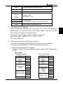
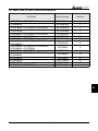
02 - 03 PWM Carrier Frequency Selections
HP
Unit: 1
Setting range
Factory setting
1-5HP
01-15KHz
15
7.5-25HP
01-15KHz
09
30-60HP
01-09KHz
06
75-100HP
01-06KHz
06
This parameter determines the PWM carrier frequency of AC drive.
Carrier Frequency
Acoustic Noise
Electromagnetic Noise,
Leakage Current
Heat Dissipation
1kHz
Significant
Minimal
Minimal
15KHz
Minimal
Significant
Significant
From the table, we see that the PWM carrier frequency has a significant influence on the
electromagnetic noise, heat dissipation of the AC drive, and the acoustic noise to the
motor.
DELTA ELECTRONICS, INC. ALL RIGHTS RESERVED
5-13
VFD-B Series
02 - 04 Motor Direction Control
Settings
Factory Setting: 00
00
Enable Forward/Reverse operation
01
Disable Reverse operation
02
Disabled Forward operation
The parameter determines the direction that AC drive can operate.
02 - 05 2-wire/ 3-wire Operation Control Modes
Settings
00
FWD/STOP, REV/STOP
01
FWD/REV, RUN/STOP
02
3-wire Operation
Factory Setting: 00
There are three different types of control modes:
External Terminal
02-05
00
2-wire
01
2-wire
FWD /STOP
REV / STOP
FWD/ REV
RUN / STOP
FWD/STOP
FWD:("OPEN":STOP)
("CLOSE":FWD)
REV/STOP
REV:("OPEN": STOP)
("CLOSE": REV)
DCM
VFD-B
RUN/STOP
FWD:("OPEN":STOP)
("CLOSE":RUN)
FWD/STOP
REV:("OPEN": F WD)
("CLOSE": REV)
DCM
VFD-B
STOP
02
3-wire
RUN
RUN/FWD
02- 06 Line Start Lockout
Settings
FWD:("CLOSE":RUN)
EF: ("OPEN":STOP)
REV:("OPEN": F WD)
("CLOSE": REV)
DCM
VFD-B
Factory Setting: 00
00
Disable
01
Enable
5-14
DELTA ELECTRONICS, INC. ALL RIGHTS RESERVED
VFD-B Series
When enabled, the AC drive will not start when powered up with run commands applied.
To start in Line Start Lockout mode, the AC drive must see the run command go from stop
to run after power up. When Line Start Lockout is disable (also known as Auto-Start), the
drive will start when powered-up with run commands applied.
The Line Start Lockout feature does not guarantee the motor will never start under this
condition. It is possible the motor may be set in motion by a malfunctioning switch.
02- 07 Loss of ACI Signal (4-20mA)
Settings
Factory Setting: 00
00
Decelerate to 0Hz.
01
Stop immediately and display “EF”.
02
Continue operation by the last frequency command.
This parameter determintes the process when ACI is lost.
02 - 08 Up/Down Key Mode
Settings
02 - 09
00
Based on Accel/Decel Time
01
Constant speed
The Acce/Decel Speed of the UP/DOWN Key with
Constant Speed
Settings
a
Factory Setting: 00
a
Factory Setting: 0.01
0.01~1.00 Hz/msec
These parameters determine increasment/decreasment method of frequency command
when the Multi-Function Input parameters Pr.04-04~Pr.04-09 are set to 11 (Up command)
or 12 (Down command).
Pr.02-08=0: It will increase/decrease frequency command by the setting of accel/decel
speed.
Pr.02-08=1: It will accel/decel frequency command by Pr.02-09.
02 - 10 Source of the Master Frequency Command (FCHA)
Settings
00
Digital keypad
01
0 to +10V from AVI
02
4 to 20mA from ACI
03
-10 to +10Vdc from AUI
04
RS-485 communication interface
DELTA ELECTRONICS, INC. ALL RIGHTS RESERVED
5-15
a
Factory Setting: 00
5
VFD-B Series
02 - 11 Source of the Auxiliary Frequency Command (FCHB)
Settings
02 - 12
00
Digital keypad
01
0 to +10V from AVI
02
4 to 20mA from ACI
03
-10 to +10Vdc from AUI
04
RS-485 communication interface
Combination of the Master and Auxiliary Frequency
Command
Settings
a
Factory Setting: 00
a
Factory Setting: 00
00
Master frequency + Auxiliary frequency
01
Master frequency - Auxiliary frequency
These three parameters (Pr.02-10~02-12) are enabled when Pr.02-00 or Pr.02-13 is set to
06. If they are enabled, the frequency command will be determined by these parameters.
02 - 15 Keyboard Frequency Command
Settings
a Factory Setting: 60.00
0.00 ~ 400.00Hz
Unit: 0.01
This parameter can be used to set frequency command or read keypad frequency
command.
5-16
DELTA ELECTRONICS, INC. ALL RIGHTS RESERVED
VFD-B Series
Group 3: Output Function Parameters
03 - 00
Multi-function Output Terminal
(Relay contact point RA, RB, RC)
Factory Setting: 08
03 - 01 Multi-function Output Terminal MO1
Factory Setting: 01
03 - 02 Multi-function Output Terminal MO2
Factory Setting: 02
03 - 03 Multi-function Output Terminal MO3
Factory Setting: 20
Settings
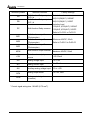
Function Table List:
Setting
00 to 28
Functions
Descriptions
00
No function
01
AC Drive Operational
The terminal will be activated when there is
an output from the drive or RUN command is
“ON”.
02
Master Frequency Attained
The output will be activated when the AC
drive attains the Output Frequency Setting.
03
Zero speed
04
Over-Torque detection
05
Baseblock (B.B.) Indication
06
Low-Voltage Indication
07
Operation Mode Indication
08
Fault Indication
09
Desired Frequency Attained 1
10
PLC Program Running
11
PLC Program Step Completed
12
PLC Program Completed
DELTA ELECTRONICS, INC. ALL RIGHTS RESERVED
The output will be activated when Command
Frequency is lower than the Minimum Output
Frequency.
The output will be activated as long as
over-torque is detected. (Refer to Pr.06-03 ~
Pr.06-05)
The output will be activated when the output
of the AC drive is shut off by external
baseblock.
The output will be activated when low voltage
is detected.
The output will be activated when operation
command is controlled by external terminal.
The output will be activated when faults occur
(oc, ov, oH, oL, oL1, EF, cF3, HPF, ocA, ocd,
ocn, GFF).
The output will be activated when the desired
frequency (Pr.03-04) is attained.
The Output will be activated when PLC
Program is running.
The Output will be activated for 0.5 sec when
each multi-step speed is attained.
The output will be activated for 0.5 sec when
the PLC program cycle has completed
5-17
5
VFD-B Series
Setting
Functions
Descriptions
The output will be activated when PLC
operation is paused.
The output will be activated when the counter
reaches Terminal Count Value.
13
PLC Operation Paused
14
Terminal Count Value Attained
15
Preliminary Count Value Attained
The output will be activated when the counter
reaches Preliminary Count Value.
Auxiliary Motor 1, 2 and 3
For the fan & pump control applications, one
can use the Multi-function Output Terminals to
define the auxiliary motor 1-3. Refer to CH
5-11 (PID Controls) and CH 5-12 (Fan and
Pump Control).
16
17
18
19
20
21
22
23
24
25
26
27
28
When heatsink overheats, it will signal to
prevent OH turn off the drive. > 85 oC (185oF)
ON, < 85oC (185 oF) OFF.
The output will be activated when the drive is
AC drive ready
on and no abnormality detected.
The contact will be activated once the
Emergency Stop Indication
drive’s emergency stop function is activated.
The output will be activated when the desired
Desired Frequency Attained 2
frequency (Pr.03-10) is attained.
This function is used in conjunction with a
VFDB Braking Unit. The output will be
Soft Braking Signal
activated when the drive needs help braking
the load. A smooth deceleration is achieved
using this function.
The output is always active unless there is an
output frequency present at terminals U/T1,
Zero Speed Output Signal
V/T2, and W/T3.
The output will be activated once the drive’s
Low-current Detection
current is too low. (Refer to Pr.06-12, 06-13)
The output will be activated when there is
Operation Indication (H>=Fmin)
output voltage from U, V, W.
The output will be activated once the
feedback signal is abnormal. (Refer to
Feedback Signal Error
Pr.10-08, Pr.10-16)
The output will be activated once the DC Bus
User-defined low-voltage Detection voltage is too low. (Refer to Pr.06-16,
Pr.06-17)
Heatsink overheat warning (OH1)
03 - 04 Desired Frequency Attained 1
Settings
Factory Setting: 0.00
0.00 to 400.00 Hz
Unit: 0.01Hz
5-18
DELTA ELECTRONICS, INC. ALL RIGHTS RESERVED
VFD-B Series
Factory Setting: 0.00
03 - 10 Desired Frequency Attained 2
Settings
0.00 to 400.00 Hz
Unit: 0.01
If a Multi-function output terminal is set to function as Desired Frequency Attained 1
(Pr.03-00 to Pr.03-03 = 09), then the output will be activated when the programmed
frequency is attained.
Freq.
Max. Output Detection range
Freq.
+
- 2Hz
Detection
range
-2Hz
Time
Desired Freq. 1
03-04
Max. Freq.
Attained
Indication OFF
03-00 to 03-03
Desired Freq.
Attained 1
OFF
Indication
03-00 to 03-03
Detection range
+
- 4Hz
ON
OFF
ON
OFF
5
Desired Freq. Attained 1 & Max. Freq. Attained
Factory Setting: 00
03 - 05 Analog Output Signal (AFM)
Settings
00
Analog Frequency Meter (from 0 to the Maximum Output
Frequency)
01
Analog Current Meter (from 0 to 250% of the rated AC drive
current)
02
Output voltage (from 0 to Pr.01-02)
03
Output frequency command (from 0 to the Maximum Frequency)
04
Output motor speed (from 0 to the Maximum Frequency)
05
Load power factor (cosθ = 90o to cosθ = 0o )
This parameter determines the meaning of the 0~+10VDC output from AFM and ACM.
03 - 06 Analog Output Gain
Settings
a
01 to 200%
Unit: 1%
This parameter sets the voltage range of the analog output signal.
DELTA ELECTRONICS, INC. ALL RIGHTS RESERVED
Factory Setting: 100
5-19
VFD-B Series
When Pr.03-05 is set to 0, the analog output voltage is directly proportional to the output
frequency of the AC drive. With Pr.03-06 set to 100%, the Maximum Output Frequency
(Pr.01-00) of the AC drive corresponds to +10VDC on the AFM output.
Similarly, if Pr.03-05 is set to 1, the analog output voltage is directly proportional to the
output current of the AC drive. With Pr.03-06 set to 100%, then 2.5 times the rated current
corresponds to +10VDC on the AFM output.
Note: Any type of voltmeter can be used. If the meter reads full scale at a voltage less than 10
volts, the parameter 03-06 should be set using the following formula:
Pr. 03-06 = ((meter full scale voltage)/10) x 100%
For Example: When using the meter with full scale of 5 volts, adjust Pr.03-06 to 50%. If
Pr.03-05 is set to 0, then 5Vdc will correspond to Maximum Output Frequency.
03 - 07 Digital Output Multiplying Factor
Settings
a
01 to 20 times
Factory Setting: 01
Unit: 1
This parameter determines the multiplying factor for the AC drives digital output frequency
at the digital output terminals (DFM-DCM). The number of output pulses per second is
equal to the AC drive output frequency multiplied by Pr.03-07. (Pulse per second = actual
output frequency x Pr.03-07)
03 - 08 Terminal Count Value
Settings
a
00 to 65500
Factory Setting: 00
Unit: 1
The parameter determines the value of the internal counter. The internal counter can be
triggered by the external terminal TRG. Upon completion of counting, the specified output
terminal will be activated. (Pr.03-00, to Pr.03-03 set to 14).
When the display shows c5555, the drive has counted 5,555 times. If display shows
c5555., it means that real counter value is between 55,550 to 55,559.
03 - 09 Preliminary Count Value
Settings
a
00 to 65500
Factory Setting: 00
Unit: 1
When the counter value is counted up from “1” to the set value of this parameter, the
corresponding multi-function output terminal will be activated, when set to 15 (Preliminary
Count Value Setting). The corresponding multi-function output terminal will be deactivated
upon completion of Terminal Count Value Attained.
5-20
DELTA ELECTRONICS, INC. ALL RIGHTS RESERVED
VFD-B Series
The timing diagram:
2msec
Display
(Pr.00-04=01)
TRG
Counter Trigger
2msec
The width of trigger signal
should not be less than
2ms(<250 Hz)
Preliminary Count Value
(Pr. 03-00~Pr. 03-03=15) Ex:03-08=5,03-09=3
Terminal Count Value
(Pr. 03-00~Pr. 03-03=14)
03 - 11 EF Active when Preliminary Count Value Attained
Settings
Factory Setting: 00
5
00
No function.
01
Preliminary count value attained, EF active.
If this parameter is set to 01, When the desired value of counter is attained, the AC drive
treat it as a fault, the drive will stop and show the “cEF” message on the display.
03 - 12 Fan Control
Settings
Factory Setting: 00
00
Always fan on
01
Power off 1 minute later, fan off
02
Run and fan on, stop and fan off
03
Preliminary temperature attained, Fan start to run
This parameter determines the operation mode of cooling fan.
DELTA ELECTRONICS, INC. ALL RIGHTS RESERVED
5-21
VFD-B Series
Group 4:
Input Function Parameters
04 - 00 AVI Analog Input Bias
Settings
a
0.00 to 200.00%
Unit: 0.01%
Factory Setting: 00
04 - 01 AVI Bias Polarity
Settings
00
Positive Bias
01
Negative Bias
04 - 02 AVI Input Gain
Settings
a
1 to 200%
00
Forward motion only
01
Forward and reverse motion enabled. Forward motion with
positive bias. Reverse motion with negative bias.
02
Forward and reverse motion enabled. Forward and Reverse
motion with positive or negative bias. Select direction via the
keypad or external terminals.
04 - 11 ACI Analog Input Bias
Settings
a
0.00 to 200.00%
Factory Setting: 00
00
Positive Bias
01
Negative Bias
04 - 13 ACI Input Gain
Settings
a
01 to 200%
Factory Setting: 00
00
No ACI Negative bias command
01
Negative bias, REV motion enabled
02
Negative bias, REV motion disabled
04 - 15 AUI Analog Input Bias
Settings
a
0.00 to 200.00%
Factory Setting: 0.00
Unit: 0.01%
Factory Setting: 00
04 - 16 AUI Bias Polarity
Settings
Factory Setting: 100
Unit: 1%
04 - 14 ACI Negative Bias, Reverse Motion Enable
Settings
Factory Setting: 0.00
Unit: 0.01%
04 - 12 ACI Bias Polarity
Settings
Factory Setting: 100
Unit: 1%
Factory Setting: 00
04 - 03 AVI Negative Bias, Reverse Motion Enabled
Settings
Factory Setting: 0.00
00
Positive Bias
01
Negative Bias
5-22
DELTA ELECTRONICS, INC. ALL RIGHTS RESERVED
VFD-B Series
04 - 17 AUI Input Gain
Settings
a
Factory Setting: 100
01 to 200%
Unit: 1%
Factory Setting: 00
04 - 18 No AUI Negative bias command
Settings
00
No ACI Negative bias command
01
Negative bias, REV motion enabled
02
Negative bias, REV motion disabled
Pr.04-00 ~ 04-03, Pr.04-11 ~ 04-18 are used when the source of frequency command is
the analog signal. Refer to the following examples.
Example 1:
Max.
Output Pr.01-00
Freq.
60Hz
Factory Settings
Pr.01-00=60Hz--Max. output Freq.
Pr.04-11=0%--bias adjustment
Pr.04-12 =0-- bias polarity
Pr.04-13=100% -- pot. freq. gain
Pr.04-14=0 -- REV disable in negative bias
30Hz
0Hz
0V
4mA
5V
12mA
10V
20mA
Example 2:
In this example with the potentiometer set to 0V the Output Frequency is 10 Hz. The mid-point
of the potentiometer becomes 40 Hz. Once the Maximum Output Frequency is reached any
further increase of the potentiometer will not increase output frequency. (If you want to use the
range of 60Hz, please refer to the example 3.) The value of external input voltage/current
0-8.33V (4-13.33mA) corresponds to the setting frequency 0-60Hz.
Pr.01-00 Max. Output Freq.
60Hz
10Hz
Bias
Adjustment
0Hz 0V
4mA
Factory Settings
Pr.01-00=60Hz--Max. output Freq.
Pr.04-11=16.7%-- bias adjustment
Pr.04-12=0 -- bias polarity
Pr.04-13=100% -- pot. freq. gain
Pr.04-14=0 -- REV motion disable in negative bias
5V
12mA
10V
20mA
DELTA ELECTRONICS, INC. ALL RIGHTS RESERVED
5-23
5
VFD-B Series
Example 3:
The example also shows the popular method. The whole scale of the potentiometer can be
used as desired. In addition to signals of 0 to 10V and 4 to 20mA, the popular voltage signals
also include signals of 0 to 5V, 20 to 4mA or that under 10V. Regarding the setting, please
refer to the following examples.
Pr.01-00 Max. Output Freq.
60Hz
10Hz
Bias
Adjustment
-2V 0Hz 0V
4mA
XV
10V
20mA
Pr. 04-13 = 10V X 100% = 83.3%
12V
Negative bias:
60-10Hz = 10-0Hz
10V
XV
100
2
XV =
= 2V
Pr.04-11 =
X 100%
50
10
Example 4:
This example shows a potentiometer range of 0 to 5 Volts. In addition to adjust gain, you also
can set Pr. 01-00 to 120Hz.
Max. Output Freq.
Pr.01-00
Gain
adjustment
60Hz
30Hz
0Hz 0V
Factory Settings
Pr.01-00=60Hz--Max. output Freq.
Pr.04-11=0.0% bias adjustment
Pr.04-12=0 -- bias polarity
Pr.04-13=200% -- pot. freq. gain
Pr.04-14=0 -- REV motion disable in negative bias
Calculation of gain
10V )X100% = 200%
5V
5V
Example 5:
In this example a 1-volt negative bias is used. In a noisy environment, it is advantageous to
use negative bias to provide a noise margin (1V in this example).
Pr.01-00 Max. Output Freq.
Factory Settings
Pr.01-00=60Hz--Max. output Freq.
Pr.04-11=10.0% -- bias adjustment
Pr.04-12=1 -- bias polarity
Pr.04-13=100% -- pot. freq. gain
Pr.04-14=0 -- Rev. motion disable in negative bias
60Hz
54Hz
0Hz
Negative
0V 1V
bias 6Hz
10V
5-24
DELTA ELECTRONICS, INC. ALL RIGHTS RESERVED
VFD-B Series
Example 6:
In this example, a negative bias is used to provide a noise margin. Also a potentiometer
frequency gain is used to allow the Maximum Output Frequency to be reached.
Max. Output Freq.
Pr.01-00
Bias
adjustment
Factory Settings
Pr.01-00=60Hz--Max. output Freq.
Pr.04-11=10%--bias adjustment
Pr.04-12=1 -- bias polarity
Pr.04-13=111% -- pot. freq. gain
Pr.04-14=0 -- REV. motion disable in negative bias
60Hz
0Hz
Negative
0V 1V
bias 6.6Hz
10V
Calculation of gain
Pr.04-13=( 10V )X100%=111%
9V
5
Example 7:
In this example, the potentiometer is programmed to run a motor in both forward and reverse
direction. A motor will be idle when the potentiometer position is at mid-point of its scale.
Using this example will disable the external FWD and REV controls.
Pr.01-00 Max. Output Freq.
60Hz
30Hz
0V 0Hz
REV
Factory Settings
FWD
5V
10V
30Hz
Pr.01-00=60Hz--Max. output Freq.
Pr.04-11=50%--bias adjustment
Pr.04-12=1 -- bias polarity
Pr.04-13=200% -- pot. freq. gain
Pr.04-14=1 -- REV motion enable in negative bias
60Hz
Example 8:
In this example, the option of anti-slope is shown. Anti-slope is used in an application where
control of pressure, temperature, or flow is needed. Under a high pressure or flow situation, a
sensor will generate a large signal such as 20 mA or 10V. With anti-slope enable, the large
signal will slow or stop the AC drive. The limit in this application is can’t change the direction
of run. For AC drive, it just can run in reverse direction.
DELTA ELECTRONICS, INC. ALL RIGHTS RESERVED
5-25
VFD-B Series
Pr.01-00 Max. Output Freq.
60Hz
Factory Settings
Pr.01-00=60Hz--Max. output Freq.
Pr.04-11=100%--bias adjustment
Pr.04-12=1 -- bias polarity
Pr.04-13=100% -- pot. freq. gain
Pr.04-14=1 -- REV. motion enable in negative bias
anti-slope
0Hz
0V
4mA
10V
20mA
04 - 04
Multi-function Input Terminal (MI1)
Factory Setting: 01
04 - 05
Multi-function Input Terminal (MI2)
Factory Setting: 02
04 - 06
Multi-function Input Terminal (MI3)
Factory Setting: 03
04 - 07
Multi-function Input Terminal (MI4)
Factory Setting: 04
04 - 08
Multi-function Input Terminal (MI5)
Factory Setting: 05
04 - 09
Multi-function Input Terminal (MI6)
Factory Setting: 06
Settings
00 to 36
Settings
Parameters & Functions Table:
Value
Functions
Descriptions
The purpose of this setting is to provide isolation for
unused Multi-Function Input Terminals. Any unused
terminals should be programmed to 0 to insure they
have no effect on drive operation.
00
No Function
01
Parameter values 1, 2, 3, 4 program any four of the
following Multi-Function Input Terminals for multi-step
speed command function. These four inputs select
the multi-step speeds defined by Pr.05-00 to Pr.05-14
Multi-Step Speed Command 2 as shown in the following diagram.
Note: Pr.05-00 to Pr.05-14 can also control output
Multi-Step Speed Command 3 speed by programming the AC drive’s internal PLC
function. There are 17 step speed frequencies
(including Master Frequency and Jog Frequency) to
Multi-Step Speed Command 4 select for application.
02
03
04
05
Multi-Step Speed Command 1
External Reset (NO)**
Parameter value 5 programs a Multi-Function Input
Terminal to be an External Reset.
Note: the External Reset has the same function as
the Reset key on the Digital keypad. After fault such
as O.H., O.C. and O.V. are clear, this input can be
used to reset the drive.
5-26
DELTA ELECTRONICS, INC. ALL RIGHTS RESERVED
VFD-B Series
Value
Functions
06
Accel/Decel Inhibit
07
Accel/Decel Time Selection
Command 1
08
Accel/Decel Time Selection
Command 2
09
External Base Block (NO)**
10
External Base Block (NC)***
11
Increase Master Frequency
12
Decrease Master Frequency
13
Counter Reset
14
Run PLC Program
15
Pause PLC Program
16
17
18
19
20
Auxiliary Motor No.1 output
failure
Auxiliary Motor No.2 output
failure
Auxiliary Motor No.3 output
failure
Emergency Stop (NO)**
Emergency Stop (NC)***
DELTA ELECTRONICS, INC. ALL RIGHTS RESERVED
Descriptions
Parameter value 6 programs Multi-Function Input
Terminal: for Accel/Decel Inhibit. When the command
is active, acceleration and deceleration is stopped
and the AC drive maintains a constant speed.
Parameter value 7, 8 programs any two of
Multi-Function Input Terminals to select the one of
four Accel/Decel Time. (Pr.01-09 to Pr.01-12, Pr.01-18
to Pr.01-21)
Parameter values 9, 10 program Multi-Function Input
Terminals for external Base Block control. Value 9 is
for normally open (N.O.) input, and value d10 is for a
normally close (N.C.) input.
Note:
When a Base-Block signal is received, the AC drive
will stop all output and the motor will free run. When
base block control is deactivated, the AC drive will
start its speed search function and synchronize with
the motor speed, and then accelerate to Master
Frequency.
Parameter values 11, 12 program the Multi-Function
Input Terminals to incrementally increase/ decrease
the Master Frequency each time an input is received.
Please refer to Pr.02-08, 02-09.
Parameter value 13 programs Multi Function Input
Terminal to reset the counter.
Parameter value 14 programs Multi-Function Input
Terminal to enable the AC drive internal PLC
program. Parameter value d15 programs an input
terminal to pause the PLC program.
Note: Pr.05-00 to Pr.05-16 defines the PLC program.
Parameter value 16 to 18 program Multi-Function
Input Terminal to disable the corresponding relay of
the AC drive multi-function output terminals, Pr.03-00
to 3-03 (MO1 to MO3).
Parameter value 19 to 20 program Multi-Function
Input Terminal to the AC drive to receive the signals of
malfunction and emergency stop. Please press
“RESET” after fault has been cleared.
5-27
5
VFD-B Series
Value
∗21
∗22
23
24
25
Descriptions
Pr.02-00 will automatically be disabled once this
Master Frequency Selection
parameter value 21 is enabled; the situation will be
AVI /ACI
determined by the terminals. If the terminal is open,
it is AVI; if closed, it is ACI otherwise.
Pr.02-00 will automatically be disabled once this
Master Frequency Selection
parameter value 22 is enabled; the situation will be
AVI/AUI
determined by the terminals. If the terminal is open,
it is AVI; if closed, it is AUI otherwise.
Pr.02-01 will automatically be disabled once this
parameter value 21 is enabled; the situation will be
Operation Command Selection
determined by the terminals. If the terminal is open,
keypad/external
it is via keypad; if closed, it is via the external
terminals otherwise.
Functions
Auto accel/decel mode disable
Forced Stop (NC)***
If enables, the auto accel/decel mode set by Pr.01-15
will be disabled
These two parameters function is the same as the
“STOP” command. It won’t display any error
message. Once parameter value 25 or 26 occurs, you
need to press “RUN” to run AC drive.
26
Forced Stop (NO)**
27
Parameter lock enable
When this setting is enabled, all parameters will be
locked, Read/write parameters is disabled.
28
PID function disabled
When this setting is enabled, PID function will be
disabled.
29
Jog Fwd/Rev command
It will be effective only when external terminal JOG is
active.
30
External Reset (NC)***
The function is the same as setting 05 but it uses in
normal close.
31
Source of second frequency
command enabled
These two functions are used to select the
first/second frequency/operation command source.
32
Source of second operation
command enabled
33
One shot PLC
The function is the same as setting 14 but the trigger
signal is a one shot pulse, for example: a push button
input. It can be cancel by “STOP” command.
34
Proximity sensor input for
simple Index function
This function should be used with Pr.04-23 ~
Pr.04-25.
5-28
DELTA ELECTRONICS, INC. ALL RIGHTS RESERVED
VFD-B Series
Value
Descriptions
Functions
35
Output Shutoff Stop (NO)**
36
Output Shutoff Stop (NC)***
AC drive will stop output and the motor free run if one
of these settings is enabled. If the state of terminal is
changed, AC drive will restart from 0Hz.
∗ Setting 21, 22: you just can set one of them at one time.
** NO: Normal Open input.
*** NC: Normal Close input.
Frequency
Master
Freq.
Accel time 4
01-20
Decel time 1
01-10
Acceleration
Delceleration
Decel time 2
01-12
Accel time 3
01-18
Accel time 2
01-11
Decel time 3
01-19
Accel time 1
01-09
RUN/STOP
PU External terminal
communication
Accel/Decel time 1 & 2
Multi-function Input
Terminals Pr.04-04 to
Pr.04-09(MI1 to MI6 7)
Accel/Decel time 3 & 4
Multi-function Input
Terminals Pr.04-04 to
Pr.04-09(MI1 to MI6 8)
1
2
3
OFF
OFF
OFF
1
4
1
2
Decel time 4
01-21
Time
3
4
ON
ON
ON
ON
Accel/Decel Time and Multi-function Input Terminals
DELTA ELECTRONICS, INC. ALL RIGHTS RESERVED
5-29
5
VFD-B Series
05-07
Frequency
05-06
05-08
05-05
05-09
05-04
05-10
05-03
05-11
05-02
05-12
05-01
JOG Freq.
05-13 01-14
05-00
05-14
Master Speed
2 3 4 5 6 7 8 9 1011 12 131415
Run Signal
1st step speed
Multi-function Terminal
Pr.04-04 to Pr.04-09
(Mi1 to MI6 1)
2nd step speed
Multi-function Terminal
Pr.04-04 to Pr.04-09
(Mi1 to MI6 2)
3rd step speed
Multi-function Terminal
Pr.04-04 to Pr.04-09
(MI1 to MI6 3)
4th step speed
Multi-function Terminal
Pr.04-04 to Pr.04-09
(MI1 to MI6 4)
ON
OFF
ON
OFF
ON
ON
ON
OFF
ON
ON
ON
ON
ON
ON
ON
ON
ON
OFF
ON
OFF
ON
Jog Freq.
Multi-Step Speed via External Terminals
04 - 10 Digital Terminal Input Debouncing Time
Settings
1 to 20m sec
Factory Setting: 1
Unit: 1
This parameter is to delay and to check the signals from digital input terminals. 1 unit is
2 msec, 2 units are 4 msec, etc. The delay time is to check if there is any noise that
causes the digital terminal malfunction.
Factory Setting: 0.05
04 - 19 AVI Analog Input Delay
Settings
0.00 to 10.00 Sec
Unit: 0.01
Factory Setting: 0.05
04 - 20 ACI Analog Input Delay
Settings
0.00 to 10.00 Sec
Unit: 0.01
Factory Setting: 0.05
04 - 21 AUI Analog Input Delay
Settings
0.00 to 10.00 Sec
Unit: 0.01
04 - 22 Analog Input Frequency Resolution
Settings
00
0.01Hz
01
0.1Hz
Factory Setting: 01
5-30
DELTA ELECTRONICS, INC. ALL RIGHTS RESERVED
VFD-B Series
04 - 23 Gear Ratio for Simple Index Function
Settings
Factory Setting: 200
4 ~ 1000
Unit: 1
04 - 24 Index Angle for Simple Index Function
Settings
Unit: 0.1
0.0 ~360.0°
04 - 25 Deceleration Time for Simple Index Function
Settings
Factory Setting: 180.0
0.00 ~100.00 sec
a
Factory Setting: 0.00
Unit: 0.01
The simple index function is to position the mechine at the same position when it stops.
The function should be used with the function 34 of Multi-Function Input Terminals.
The system diagram is shown below. The mechine is drived by the gear motor or other
reduction gear. The trigger position of sensor is used as the original point of index
angle. When the stop command is accepted, the AC drive will not decelerate until the
sensor is trigged, then the AC drive begin to decelerate and stop according to the
Pr.04-24 and Pr.04-25.
DELTA ELECTRONICS, INC. ALL RIGHTS RESERVED
5-31
5
VFD-B Series
Group 5: Multi-step Speed and PLC (Process Logic Control) Parameters
05 - 00 1st Step Speed Frequency
a
Factory Setting: 0.00
05 - 01 2nd Step Speed Frequency
a
Factory Setting: 0.00
05 - 02 3rd Step Speed Frequency
a
Factory Setting: 0.00
05 - 03 4th Step Speed Frequency
a
Factory Setting: 0.00
05 - 04 5th Step Speed Frequency
a
Factory Setting: 0.00
05 - 05 6th Step Speed Frequency
a
Factory Setting: 0.00
05 - 06 7th Step Speed Frequency
a
Factory Setting: 0.00
05 - 07 8th Step Speed Frequency
a
Factory Setting: 0.00
05 - 08 9th Step Speed Frequency
a
Factory Setting: 0.00
05 - 09 10th Step Speed Frequency
a
Factory Setting: 0.00
05 - 10 11th Step Speed Frequency
a
Factory Setting: 0.00
05 - 11 12th Step Speed Frequency
a
Factory Setting: 0.00
05 - 12 13th Step Speed Frequency
a
Factory Setting: 0.00
05 - 13 14th Step Speed Frequency
a
Factory Setting: 0.00
05 - 14 15th Step Speed Frequency
a
Factory Setting: 0.00
Settings
0.00 to 400.00 Hz
Unit: 0.01Hz
The Multi-Function Input Terminals (refer to Pr.04-04 to 04-09) are used to select one of
the AC drive Multi-Step speeds. The speeds (frequencies) are determined by Pr.05-00
to 05-14 shown above. Also can be accompanied with Pr.05-15 to 05-31 for PLC
programs.
05 - 15 PLC Mode
Settings
Factory Setting: 00
00
Disable PLC operation
01
Execute one program cycle
02
Continuously execute program cycles
03
Execute one program cycle step by step
04
Continuously execute program cycles step by step
This parameter selects the mode of PLC operation for the AC drive. The AC drive will
change speeds and directions according to the user’s desired programming.
5-32
DELTA ELECTRONICS, INC. ALL RIGHTS RESERVED
VFD-B Series
Example 1 (Pr.05-15 = 1): Execute one cycle of the PLC program. Its relative parameter
settings are:
Pr.05-00 to 05-14:
1st to 15th step speed (sets the frequency of each step speed)
Pr.04-04 to 04-09:
Multi-Function Input Terminals (set one multi-function terminal as
14 - PLC auto-operation).
Pr.03-00 to 03-03:
Multi-Function Output Terminals (set a Multi-Function Terminal as
10-PLC running indication, 11-PLC step completed or 12-PLC
program completed).
Pr.05-16:
Direction of operation for the 1st to 15th step speed.
Pr.05-17 to 05-31:
Operation time setting of the 1st to 15th step speed.
5
Program operation
command
Program operation
indication
Step operation
indication
Program operation
fulfillment indication
Note: The above diagram shows one complete PLC cycle. To restart the cycle, turn the PLC
program off and on again.
Example 2 (Pr.05-15 = 2): Continuously executes program cycles:
The diagram above shows the PLC program stepping through each speed. Set Pr.05-15 to 2
continuously executes the program. To stop the PLC program, one must either pause the
program or turn it off. (Refer to Pr.04-04 to 04-09 values 14 and 15).
DELTA ELECTRONICS, INC. ALL RIGHTS RESERVED
5-33
VFD-B Series
Example 3 (Pr.05-15 = 3) Execute one cycle step by step:
The example below shows how the PLC can perform one cycle at a time, within in a complete
cycle. Each step will use the accel/decel times in Pr.01-09 to Pr.01-12. It should be noticed
that the time each step spends at its intended frequency is diminished, due to the time spent
during accel/decel.
Frequency
PLC operation execution one cycle step by step
05-03
05-02
05-01
05-00
1
05-17
Program operation
command
OFF
Program operation
indication
OFF
2
t
05-18
3
05-19
t
4
t
Time
05-20
ON
ON
ONON
ON
Step operation
OFF
indication
Factory Setting: 00
05 - 16 PLC Forward/Reverse Motion
Settings
00 to 32767
This parameter controls the direction of motion for the Multi-Step Speeds Pr.05-00 to
Pr.05-14 during PLC mode. All other direction commands are invalid during the PLC
mode.
Note:
The equivalent 15-bit number is used to program the forward/reverse motion for each of
the 15 speed steps. The binary notation for the 15-bit number must be translated into
decimal notation and then entered.
5-34
DELTA ELECTRONICS, INC. ALL RIGHTS RESERVED
VFD-B Series
Weights
Bit 15 14 13 12 11 10 9 8
7
6
5
4
3
2
1
0
0=Forward
1=Reverse
Direction of 1st speed for Pr.05-00
Direction of 2nd speed for Pr.05-01
Direction of 3rd speed for Pr.05-02
Direction of 4th speed for Pr.05-03
Direction of 5th speed for Pr.05-04
Direction of 6th speed for Pr.05-05
Direction of 7th speed for Pr.05-06
Direction of 8th speed for Pr.05-07
Direction of 9th speed for Pr.05-08
Direction of 10th speed for Pr.05-09
Direction of 11th speed for Pr.05-10
Direction of 12th speed for Pr.05-11
Direction of 1 3th speed for Pr.05-12
Direction of 14th speed for Pr.05-13
Direction of 15th speed for Pr.05-14
Weights
Bit
0
1
0
0
1 1
0 0
0
1
1
1
0
0
1
0
0=Forward
1=Reverse
Direction of Pr.05-00, 1st speed = Forward
Direction of Pr.05-01,2nd speed=Reverse
Direction of Pr.05-02 ,3rd speed=Forward
Direction of Pr.05-03 ,4th speed=Forward
Direction of Pr.05-04 ,5th speed=Reverse
Direction of Pr.05-05,6th speed=Reverse
Direction of Pr.05-06,7th speed=Reverse
Direction of Pr.05-07,8th speed=Forward
Direction of Pr.05-08,9th speed=Forward
Direction of Pr.05-09,10th speed=Forward
Direction of Pr.05-10,11th speed=Reverse
Direction of Pr.05-11,12th speed=Reverse
Direction of Pr.05-12, 13th speed=Forward
Direction of Pr.05-13,14th speed=Forward
14
13
Direction of Pr.05-14,15th speed=Reverse
2
1
The setting value = bit14x2 + bit13x2 +....+bit2x2 +bit1x2 +bit0x2
14
11
10
6
5
4
1
= 1x2 + 1x2 +1x2 +1x2 +1x2 +1x2 +1x2
=16384+2048+1024+64+32+16+2
=19570
Setting 05-16 =19570
NOTE:
14
2 =16384
9
2 =512
4
2 =16
13
2 =8192
8
2 =256
3
2 =8
12
2 =4096
7
2 =128
2
2 =4
DELTA ELECTRONICS, INC. ALL RIGHTS RESERVED
11
2 =2048
6
2 =64
1
2 =2
5-35
10
2 =1024
5
2 =32
0
2 =1
0
5
VFD-B Series
05 - 17 Time Duration of 1st Step Speed
Factory Setting: 0.0
05 - 18 Time Duration of 2nd Step Speed
Factory Setting: 0.0
05 - 19 Time Duration of 3rd Step Speed
Factory Setting: 0.0
05 - 10 Time Duration of 4th Step Speed
Factory Setting: 0.0
05 - 21 Time Duration of 5th Step Speed
Factory Setting: 0.0
05 - 22 Time Duration of 6th Step Speed
Factory Setting: 0.0
05 - 23 Time Duration of 7th Step Speed
Factory Setting: 0.0
05 - 24 Time Duration of 8th Step Speed
Factory Setting: 0.0
05 - 25 Time Duration of 9th Step Speed
Factory Setting: 0.0
05 - 26 Time Duration of 10th Step Speed
Factory Setting: 0.0
05 - 27 Time Duration of 11th Step Speed
Factory Setting: 0.0
05 - 28 Time Duration of 12th Step Speed
Factory Setting: 0.0
05 - 29 Time Duration of 13th Step Speed
Factory Setting: 0.0
05 - 30 Time Duration of 14th Step Speed
Factory Setting: 0.0
05 - 31 Time Duration of 15th Step Speed
Factory Setting: 0.0
Settings
0.0 to 65500
Unit: 1 /0.1sec
Pr.05-17 to Pr.05-31 correspond to operation time of each step speed defined by
Pr.05-00 to Pr.05-14. The maximum setting 65500 seconds will be displayed as t6550. If
it is displayed t6550. that means 6550 seconds.
Note: If a parameter is set to “00” (0 sec), the corresponding step will be skipped.
commonly used to reduce the number of program steps
05 - 32 Time Unit Settings
Settings
This is
Factory Setting: 00
00
1 Sec
01
0.1 Sec
This parameter determines the time unit for Pr.05-17~Pr.05-31.
05 - 33 Skip Frequency Width
Settings
Factory Setting: 0.00
0.00〜400.00 Hz
05 - 34 Bias Frequency Width
Settings
Factory Setting: 0.00
0.00〜400.00 Hz
Frequency of ∆ top point Fup= master frequency F + Pr.05-33 + Pr.05-34.
Frequency of ∆ down point Fdown= master frequency F – Pr.05-33 – Pr.05-34.
5-36
DELTA ELECTRONICS, INC. ALL RIGHTS RESERVED
VFD-B Series
Fup
Double Pr. 05-34
Pr.01-09
Master Pr.01-11
Frequency
(F)
Pr.05-33
Pr.01-10
Pr.01-12
Fdown
5
DELTA ELECTRONICS, INC. ALL RIGHTS RESERVED
5-37
VFD-B Series
Group 6:
Protection Parameters
06 - 00 Over-Voltage Stall Prevention
Settings
00
Factory Setting: 390V
Disable Over-Voltage Stall Prevention
230V series: 330 ~ 410V
460V series: 660 ~ 820V
During deceleration, the DC bus voltage may exceed its Maximum Allowable Value due
to motor regeneration. When this function is enabled, the AC drive will not decelerate
and keep the output frequency until the voltage drops below the preset value.
Note:
With moderate inertial load, the over-voltage stall prevention will not occur and the real
deceleration time should be equal to the setting of deceleration time. The AC drive will
automatically extend the deceleration time with high inertial loads. If deceleration time is
critical for the application, then dynamic braking resistor should be used.
Output Frequency
Deceleration characteristic
when Over-Voltage Stall
Prevention enabled
Frequency Held
Time
Deceleration Time
01-10, 01-12, 01-19, 01-21
06 - 01 Over-Current Stall Prevention during Acceleration
Settings
20 to 250%
Factory Setting: 170
Unit: 1%
A setting of 100% is equal to the Rated Output Current of the drive.
During acceleration, the AC drive output current may increase abruptly and exceed the
value specified by Pr.06-01 due to rapid acceleration or excessive load on the motor.
When this function is enabled, the AC drive will stop accelerating and keep the output
frequency until the current drops below the maximum value.
5-38
DELTA ELECTRONICS, INC. ALL RIGHTS RESERVED
VFD-B Series
Over-Current
Detection
Level
Current
06-01
Output Frequency
Over-Current Stall
prevention during
Acceleration,
frequency held
Factory Setting: 170
06 - 02 Over-current Stall Prevention during Operation
Settings
20 to 250%
Unit: 1%
If the output current exceeds the setting specified in Pr.06-02 (the over-current stall
prevention current level during operation) when the drive is operating, the drive will
decrease its output frequency to prevent the motor stall. If the output current is lower
than the setting specified in Pr.06-02, the drive will then accelerate to catch up with the
frequency specified.
Over-Current
Detection
Level
Output Current
06-02
Over-Current Stall
Prevention during
Operation, output
frequency decrease
Output
Frequency
DELTA ELECTRONICS, INC. ALL RIGHTS RESERVED
5-39
5
VFD-B Series
06 - 03 Over-Torque Detection Mode (OL2)
Settings
Factory Setting: 00
00
Over-Torque detection disabled.
01
Over-Torque detection enabled during constant speed operation,
and keep operation after the over-torque is detected.
02
Over-Torque detection enabled during constant speed operation,
and operation halted after over-torque detection.
03
Over-Torque detection enabled during acceleration, and keep
operation after the over-torque is detected.
04
Over-Torque detection enabled during acceleration, and
operation halted after over-torque detection
This parameter determines the operation mode of the drive after the over-torque is
detected with the following method: if the output current exceeds the over-torque
detection level (Pr.06-04) and which also exceeds the setting of Pr.06-05 Over-Torque
Detection Time, with the [Multi-Functional Output Terminal] specified as an indication for
the over-torque detection, the contact will then be “closed”.
Pr.03-00~03-03 for detail.
06 - 04
Over-Torque Detection Level
Settings
Please refer to
Factory Setting: 150
10 to 200%
Unit: 1%
This setting is proportional to the Rated Output Current of the drive.
06 - 05
Over-Torque Detection Time
Settings
Factory Setting: 0.1
0.1 to 60.0Sec
Unit: 0.1sec
This parameter determines the time for over-torque detection.
06 - 06 Electronic Thermal Overload Relay Selection
Settings
Factory Setting: 00
00
Operate with a Standard Motor (coaxial heat dissipation)
01
Operate with a Special Motor (independent heat dissipation)
02
Operation disabled
This function is used to protect the motor from overload or overheat.
06 - 07 Electronic Thermal Characteristic
Settings
Factory Setting: 60
a
30 to d 600 Sec
Unit: 1 Sec
2
The parameter determines the time required activating the I t electronic thermal
protection function. The graph below shows I2t curves for 150% output power for 1
minute.
5-40
DELTA ELECTRONICS, INC. ALL RIGHTS RESERVED
VFD-B Series
Operation
time(min)
5
60Hz or more
4
50Hz
3
10Hz
2
5Hz
1
0
Load
factor
(%)
20 40
60
80 100 120 140 160 180 200
5
06 – 08 Present Fault Record
Factory Setting: 00
06 - 09 Second Most Recent Fault Record
Factory Setting: 00
06 - 10 Third Most Recent Fault Record
Factory Setting: 00
06 - 11 Fourth Recent Fault Record
Factory Setting: 00
Settings
00
No fault occurred
01
Over-current (oc)
02
Over-voltage (ov)
03
Overheat (oH)
04
Overload (oL)
05
Overload1 (oL1)
06
External fault (EF)
07
IGBT protection (occ)
08
CPU failure (CF3)
09
Hardware protection failure (HPF)
10
Current exceeds 2 times rated current during accel.(ocA)
11
Current exceeds 2 times rated current during decel.(ocd)
12
Current exceeds 2 times rated current during steady state
operation (ocn)
13
Ground fault (GFF)
14
Low voltage (Lv)
15
CPU READ failure (CF1)
16
CPU WRITE failure (CF2)
DELTA ELECTRONICS, INC. ALL RIGHTS RESERVED
5-41
VFD-B Series
17
External Base block stop (bb)
18
Motor over load (oL2)
19
Auto accel/decel failure (CFA)
20
Software/password protection (code)
21
Emergency stop (EF1)
22
PHL (Phase-Loss)
23
cEF (Preliminary count value attained, EF active)
24
Lc (Low-current)
25
AnLEr (Analog feedback signal error)
26
PGErr (PG feedback signal error)
Pr.06-08 to Pr.06-11 store records of the four most recent faults that had occurred. Use
the reset key to reset the drive when the fault no longer exits.
06 - 12 Low-Current Detection Level
Settings
00
Factory Setting: 00
Disabled
00 ~ 100%
06 - 13 Low-Current Detection Time
Settings
Factory Setting: 10.0
0.1~ 3600.0 Sec
Unit: 0.1sec
06 - 14 Low-Current Treatment
Settings
Factory Setting: 00
00
Warn and keep operating
01
Warn and ramp to stop
02
Warn and coast to stop
03
Warn, after coast to stop, restart (delay 06-15 setting time)
06 - 15 Low-Current Detection Restart Delay Time
Settings
1~600.0 Min.
Factory Setting: 10.0
Unit: 1min
If output current is lower than Pr.06-12 and exceed the time that Pr.06-13 sets during
running, AC drive will warn as Pr.06-14 sets. If Pr.06-14 is set to 03, AC drive will restart
after the delay time set by Pr.06-15 is up.
5-42
DELTA ELECTRONICS, INC. ALL RIGHTS RESERVED
VFD-B Series
06 - 16 User-Defined Low-Voltage Detection Level
Settings
00
Factory Setting: 00
Disabled
230V series: 220 ~ 300VDC
460V series: 440 ~ 600VDC
06 - 17 User-Defined Low-Voltage Detection Time
Settings
0.1~ 3600.0 Sec
Factory Setting: 0.5
Unit: 0.1sec
When the voltage of DC BUS is lower than Pr.06-16 and the time exceeds the setting of
Pr.06-17, AC drive will output a signal by the setting 28 of Pr.03-00 ~ Pr.03-03.
06 - 18 Reserved
5
DELTA ELECTRONICS, INC. ALL RIGHTS RESERVED
5-43
VFD-B Series
Group 7:
Motor Parameters
07 - 00 Motor Rated Current
Settings
a
Factory Setting: 100
30 to 120%
Unit: 1%
Use the following method to calculate the percentage entered in this parameter.
(Motor Rated Current (Ampere)/ AC Drive Rated output current (Pr00-01)) x 100%
Pr.07-00 and Pr.07-01 must be set if the drive is programmed to operate in Vector
Control mode (Pr.0-09 = 2, 3). It also must be set if the "Electronic Thermal Overload
Relay" (Pr.06-06) or "Slip Compensation" functions is selected.
07 - 01 Motor No-load Current
Settings
a
Factory Setting: 40
01 to 90%
Unit: 1%
The rated current of the AC drive is regarded as 100%. The setting of the Motor no-load
current will effect the slip compensation.
The setting value must be less than the Pr.07-00 (Motor Rated Current).
a
07 - 02 Torque Compensation
Settings
Factory Setting: 0.0
0.0 to 10.0
Unit: 0.1
This parameter may be set so that the AC drive will increase its voltage output to obtain
a higher torque. Only for V/F control mode.
07 - 03 Slip Compensation (Used without PG)
Settings
a
Factory Setting: 0.00
0.00 to 3.00
Unit: 0.1
While driving an asynchronous motor, increasing load on the AC drive will cause an
increase in slip. This parameter may be used to compensate the slip by increasing the
output frequency. When the output current of the AC drive is greater than the motor
no-load current (Pr.07-01), the AC drive will adjust its output frequency according to this
parameter.
Factory Setting: 04
07 - 04 Number of Motor Poles
Settings
02 to 10
Unit: 2
This parameter sets the number of motor poles (must be an even number).
Factory Setting: 00
07 - 05 Motor Parameters Auto Tuning
Settings
00
Disable
Unit: 1
01
Auto Tuning R1
02
Auto Tuning R1 + No-load Test
5-44
DELTA ELECTRONICS, INC. ALL RIGHTS RESERVED
VFD-B Series
It will auto detect by pressing RUN key after this parameter is set to 01 or 02. When
setting to 01, it just auto detect R1 value, and the Pr.07-01 needed to input by manual.
When setting to 02, AC drive should be no-load and the value of Pr.07-01 and Pr.07-06
will be filled automatically.
The steps to AUTO-Tuning are:
1. Make sure that all the parameters are set to factory settings and the wiring
connected to motor is correctly.
2. Make sure that motor is no-load before auto-tuning and the axis doesn’t connect to
any belt or gear motor.
3. Fill in Pr.01-02, Pr.01-01, Pr.07-00, Pr.07-04 and Pr.07-08 with correct value.
4. After Pr.07-05 is set to 1 or 2, the AC drive will execute auto-tuning immediately as
soon as it receives the ”RUN” command The execution time will be 15 seconds +
Pr.01-09 + Pr.01-10. (The more horsepower needs the more Accel/decel time)
5. After executing, please check if there are values filled in Pr.07-01 and Pr.07-06. If
not, please press RUN key after setting Pr.07-05.
6. Then, you can set Pr.00-09 to 02/03 and set other parameters according to your
requirement.
Note 1: It is not suitable for many motors run with parallel in vector control mode.
Note 2: It is not suitable for using in vector control mode if | horsepower of motor | | horsepower of AC drive | doesn’t exceed the useful range.
Factory Setting: 00
07 - 06 Motor Line-to-line Resistance R1
Settings
Unit: 01
00 to 65535 mΩ
The motor auto detection will set this parameter. The user may also set this parameter
without using Pr.07-05.
07 - 07 Reserved
Factory Setting: 3.00
07 - 08 Motor Rated Slip
Settings
0.00 to 20.00Hz
Unit: 0.01
Refer to the rated rpm on the nameplate of the motor and use the following equation to
determine the rated slip.
Rated Slip = F (Pr.01-01 base frequency) – (rated rpm x motor pole/120)
DELTA ELECTRONICS, INC. ALL RIGHTS RESERVED
5-45
5
VFD-B Series
Factory Setting: 200
07 - 09 Slip Compensation Limit
Settings
00 to 250%
Unit: 1
This parameter can set the upper limit of the compensation frequency (the percentage
of Pr.07-08).
07 - 10 Reserved
07 - 11 Reserved
07 - 12 Torque Compensation Time Constant
Settings
0.01 ~10.00 Sec
Unit: 0.01
Factory Setting: 0.10
07 - 13 Slip Compensation Time Constant
Settings
Factory Setting: 0.05
0.05 ~10.00 Sec
Unit: 0.01
Setting the Pr.07-12 and Pr.07-13 can change the response time for the compensation.
07 - 14 Accumulative Motor Operation Time (Min.)
Settings
00 ~1439
Unit: 01
Factory Setting: 00
07 - 15 Accumulative Motor Operation Day
Settings
Factory Setting: 00
00 ~65535
Unit: 01
Pr.07-14 and Pr.07-15 are used to record the motor operation time. They can be cleared
by setting to 00 and won’t record if the time is less than 60 seconds.
5-46
DELTA ELECTRONICS, INC. ALL RIGHTS RESERVED
VFD-B Series
Group 8: Special Parameters
Factory Setting: 0
08 - 00 DC Braking Current Level
Settings
0 to 100%
Unit: 1%
This parameter determines the level of DC Braking Current output to the motor during
start-up and stopping. When setting DC Braking Current, the Rated Current (Pr.00-01)
is regarded as 100%. It is recommended to start with a low DC Braking Current Level
and then increase until proper holding torque has been attained.
08 - 01 DC Braking Time during Start-up
Settings
Factory Setting: 0.0
0.0 to 60.0 sec
Unit: 0.1sec
This parameter determines the duration that the DC Braking current will be applied to
the motor during the AC drive start-up. When the time is up, the AC drive will start
acceleration from the Minimum Frequency (Pr.01-05).
Factory Setting: d 0.0
08 - 02 DC Braking Time during Stopping
Settings
0.0 to 60.0 sec
Unit: 0.1sec
This parameter determines the duration that the DC Braking current will be applied to
the motor during stopping. If stopping with DC Braking is desired, the Pr.02-02 must be
set to RAMP stop.
08 - 03 Start-Point for DC Braking
Settings
Factory Setting: 0.00
0.00 to 400.00Hz
Unit: 0.01Hz
This parameter determines the frequency that the DC Braking will begin while the output
Frequency reached during deceleration.
Output Frequency
Start-Point for
DC Braking
Time during
Stopping
01-05
08-03
Minimum Output
Frequency
DC Braking Time
during Stopping
Run/Stop
OFF
ON
NOTE: 1. DC Braking during Start-up is used for loads that may move before the AC drive
starts, such as fans and pumps. Under such circumstances, DC Braking can be
executed to hold the load in position before applying a forward motion.
DELTA ELECTRONICS, INC. ALL RIGHTS RESERVED
5-47
5
VFD-B Series
2. DC Braking during stopping is used to shorten stopping time and also to hold a
stopped load in position. For high inertial loads, a dynamic braking resistor may
also be needed for quick decelerations.
Factory Setting: 00
08 - 04 Momentary Power Loss Operation Selection
Settings
00
Operation stops after momentary power loss.
01
Operation continues after momentary power loss, speed search
starts with the Master Frequency reference value.
02
Operation continues after momentary power loss, speed search
starts with the minimum frequency.
This parameter determines the operation mode when the AC drive restart from a
momentary power loss.
08 - 05 Maximum Allowable Power Loss Time
Settings
0.1 to 5.0 sec
Factory Setting: 2.0
Unit: 0.1sec
If the power loss time is less than this parameter setting, the AC drive will resume
operation, or if exceed the Maximum Allowable Power Loss Time, the AC drive output is
then turned off.
08 - 06 Baseblock Time for Speed Search (BB)
Settings
0.1 to 5.0 sec
Factory Setting: 0.5
Unit: 0.1sec
When momentary power loss is detected, the AC drive will stop its output, and then wait
for a specified period of time (determined by Pr.08-06, called Base-Block) before
resuming the operation. Setting of this parameter should be the residual voltage with a
close-to-0V value on the output end before the drive is activated again.
This parameter could also determine the searching time when performing External
Baseblock and Auto Restart after Fault (Pr.08-14).
Factory Setting: 150
08 - 07 Current Limit for Speed Search
Settings
30 to 200%
Unit: 1%
This parameter limit the current output when the Drive operates in speed search mode.
When executing speed search, V/F curve will base on the setting of Group 01.
5-48
DELTA ELECTRONICS, INC. ALL RIGHTS RESERVED
VFD-B Series
Power
Input
08-05
Maximum Allowable
Power Loss Time
Speed Search
Output
Frequency
08-04=01
Baseblock Time
Speed
Synchronization
Detection
08-06
08-05
Maximum
Allowable Power
08-04=02
Baseblock Time
08-06
Output
Voltage
08 - 08 Skip Frequency 1 Upper Bound
Factory Setting: 0.00
08 - 09 Skip Frequency 1 Lower Bound
Factory Setting: 0.00
08 - 10 Skip Frequency 2 Upper Bound
Factory Setting: 0.00
08 - 11 Skip Frequency 2 Lower Bound
Factory Setting: 0.00
08 - 12 Skip Frequency 3 Upper Bound
Factory Setting: 0.00
08 - 13 Skip Frequency 3 Lower Bound
Factory Setting: 0.00
Settings
0.00 to 400.00Hz
Unit: 0.01Hz
These parameters select the Skip Frequency. It will cause the AC drive to skip operation
at these frequency ranges with continuous frequency output.
Pr.08-09, Pr.08-11, Pr.08-13 are for Lower Bound setting, and the settings should follow
as Pr.08-09 ≧ Pr.08-11 ≧ Pr.08-13.
Factory Setting: 00
08 - 14 Auto Restart After Fault
Settings
00 to 10
Unit: 1
After fault occurs (allowable faults: over-current OC, over-voltage OV), the AC drive can
be reset/restarted automatically up to 10 times. Setting this parameter to 0 will disable
the reset/restart operation after any fault has occurred. When enabled, the AC drive will
restart with speed search, which starts at the Frequency before fault.
Factory Setting: 00
08 - 15 Automatic energy-saving
Settings
00
Energy-saving operation disabled
01
Energy-saving operation enabled
DELTA ELECTRONICS, INC. ALL RIGHTS RESERVED
5-49
5
VFD-B Series
Output
Voltage
100%
70%
During the auto energy-saving
operation, it will adjust the output
voltage according to the output
power. The maximum output
voltage can be 30% lower than
the normal output voltage.
Output Frequency
Factory Setting: 00
08 - 16 Automatic Voltage Regulation (AVR)
Settings
00
AVR function enabled
01
AVR function disabled
02
AVR function disabled for deceleration
The rated voltage of motor is usually AC220V/200V, 60Hz/50Hz and the input voltage of
AC drive is AC 180V ~ 264V, 50Hz/60Hz. When AC drive runs without AVR function, if
input power is AC 250V and the output voltage to motor will also be AC 250V. The
voltage exceeds 12% ~ 20% of the rated voltage. When motor runs in the higher voltage,
the temperature of motor will be risen, the insulation will be destroyed and the output of
torque will be unsteadily. The motor will be short life if using in these situation for a long
time.
This function will make the output power stay on the rated voltage of motor when input
power exceeds the rated voltage of motor. For example, V/F curve is set to AC
200V/50Hz, input power is AC 200 ~ 264V, the voltage that output to motor will be AC
200V/50Hz and not exceed the setting voltage. If the input power vary between AC 180
~ 200V, the voltage that output to motor will be the same ratio with input power.
Selecting program value 2 enables the AVR function and will disables the AVR function
during deceleration. This offers a quicker deceleration.
08 - 17
Software Setting of the Braking Level
(the Action Level of the Braking Resistor)
Settings
Unit: 1
230V series: 370 to 430V
Factory Setting: 380
460V series: 740 to 860V
Factory Setting: 760
5-50
DELTA ELECTRONICS, INC. ALL RIGHTS RESERVED
VFD-B Series
This parameter is the software setting utilized in controlling the braking Resistor; please
refer to the DC voltage value on the DC-BUS for reference.
08 - 18 Base block Speed Search
Settings
Factory Setting: 00
00
Speed search starts with last frequency command
01
Starts with minimum output frequency (Pr.01-05)
This parameter determines the AC drive restart method after base block is enabled.
6
3
1
O utput frequency
(H)
2 Stop output voltage
4
Output voltage
(V)
3 Disable B.B. signal
2
4 Waiting time 08-06
5 Speed search
08-07
08-06
Current Limit
Baseblock
time for
for
Speed
Search
speed
search
A
6 Synchronization speed detection
output current
Time
FW D Run
5
1
B.B.
F ig 1: B.B. Speed Search with Last Out put Frequency Downward Timing Chart
(Speed Search Current Attains Speed Search Level)
6
3
O utput frequency
( H)
1 Input B.B. signal
2 Stop output voltage
4
O utput voltage
(V)
3 Disable B.B. signal
2
4 Waiting time
5 Speed search
08-07
Current Limit08-06
for
Speed search
level
Speed
Search
A
6 Synchronization speed detection
Output current
Time
FWD R un
5
1
B.B.
Fig 2: B.B. Speed Search with Last Output Frequency Downward Timing Chart
(Speed Search Current doesn't Attain Speed Search Level)
DELTA ELECTRONICS, INC. ALL RIGHTS RESERVED
5-51
5
VFD-B Series
3
7
5
Output frequency
(H)
1
2 Stop output voltage
4
Output voltage
(V)
06-01
Over current
stall prevention
during acceleration
3 Disable B.B. signal
2
4 Waiting time 08-06
5 Restart
6
A
6 Stall prevention
7 Keep accelerating
Time
FWD Run
1
B.B.
Fig 3: B.B. Speed Search with Minimum Output Frequency Upward Timing Chart
(Start-up Current Attains Stall Current Level)
Factory Setting: 00
08 - 19 Speed Search during Start-up
Settings
00
Speed search disable
01
Speed search enable
This parameter is used for starting and stopping a motor with high inertia. A motor with
high inertia will take a long time to stop completely. By setting this parameter, the user
does not need to wait for the motor to come to a complete stop before restarting the AC
drive. If a PG card and encoder is being used on the drive and motor, then the speed
search will start from the speed that is detected and accelerate quickly to the
commanded frequency. Pr.08-04 and Pr.08-06 will be disabled when using this
parameter with PG feedback control.
Note: Please make sure Pr.07-04, Pr.10-10, and Pr.10-11 are set correctly. An incorrect
setting may cause the motor to exceed its speed limit and permanent damage to the
motor and machine can occur.
08 - 20 Speed Search Frequency during Start-up
Settings
a
00
Setting Frequency
01
Maximum Operation Frequency (01-00)
Factory Setting: 00
This parameter determines the start frequency of speed search frequency.
5-52
DELTA ELECTRONICS, INC. ALL RIGHTS RESERVED
VFD-B Series
Factory Setting: 600
08 - 21 Auto Reset Time at Restart after Fault
Settings
00 to 60000 sec
Unit: 1
This parameter should be used with Pr.08-14. For example: Pr.08-14 is set to 10 and
Pr.08-21 is set to 600s (10 min), if there is no fault over 600 seconds from the restart for
the previous fault, the auto reset times for restart after fault will be reset to 10.
08 - 22 Compensation Coefficient for Motor Instability
Settings
00~1000
a
Factory Setting: 00
Unit: 1
This parameter can improve the motor instability situation.
5
DELTA ELECTRONICS, INC. ALL RIGHTS RESERVED
5-53
VFD-B Series
Group 9:
Communication Parameters
09 - 00 Communication Address
Settings
a
Factory Setting: 01
01 to 254
If the AC drive is controlled by RS-485 serial communication, the communication
address for this drive must be set via this parameter.
09 - 01 Transmission Speed
Settings
a
Factory Setting: 01
00
Baud rate 4800 (data transmission speed: bits / second)
01
Baud rate 9600 (data transmission speed: bits / second)
02
Baud rate 19200 (data transmission speed: bits / second)
03
Baud rate 38400 (data transmission speed: bits / second)
Users can set parameters and control the operation of the AC drive via the RS-485
serial interface of a personal computer. This parameter is used to set the transmission
speed between the computer and AC drive.
09 - 02 Transmission Fault Treatment
Settings
a
00
Warn and keep operating
01
Warn and RAMP to stop
02
Warn and COAST to stop
03
No warning and keep operating
Factory Setting: 03
This parameter is set to detect if an error occurs and take actions.
09 - 03 Time Out Detection
Settings
0.0
a
Factory Setting: 0.0
Disable
0.0 ~ 60.0 sec
Unit: 1
If Pr09-03 is not equal to zero, Pr09-02=0~2, and there are not any communication on
the bus during setting time period (set by Pr. 09-03), “cE10” will be shown on the
keypad.
09 - 04 Communication Protocol
Settings
a
00
Modbus ASCII mode, protocol <7,N,2>
01
Modbus ASCII mode, protocol <7,E,1>
02
Modbus ASCII mode, protocol <7,O,1>
03
Modbus RTU mode, protocol <8,N,2>
04
Modbus RTU mode, protocol <8,E,1>
05
Modbus RTU mode, protocol <8,O,1>
5-54
Factory Setting: 00
DELTA ELECTRONICS, INC. ALL RIGHTS RESERVED
VFD-B Series
1. Computer Control
There is a built-in RS-485 serial interface, marked (RJ-11 Jack) on the control
terminal block. The pins are defined below:
6
1
1: EV
2: GND
3: SG4: SG+
5: NC
6: for communication
Each VFD-B AC drive has a pre-assigned communication address specified by
Pr.09-00. The computer then controls each AC drive according to its communication
address.
A VFD-B can be setup to communicate on Modbus networks using one of the
following modes: ASCII (American Standard Code for Information Interchange) or
RTU (Remote Terminal Unit). Users can select the desired mode along with the
serial port communication protocol in Pr.9-04.
Code Description:
ASCII mode:
Each 8-bit data is the combination of two ASCII characters. For example, a 1-byte
data: 64 Hex, shown as ‘64’ in ASCII, consists of ‘6’ (36Hex) and ‘4’ (34Hex).
Character
ASCII code
Character
ASCII code
RTU mode:
‘0’
‘1’
‘2’
‘3’
‘4’
‘5’
‘6’
‘7’
30H
31H
32H
33H
34H
35H
36H
37H
‘8’
‘9’
‘A’
‘B’
‘C’
‘D’
‘E’
‘F’
38H
39H
41H
42H
43H
44H
45H
46H
Each 8-bit data is the combination of two 4-bit hexadecimal characters. For example,
64 Hex.
2. Data Format
10-bit character frame (For ASCII):
DELTA ELECTRONICS, INC. ALL RIGHTS RESERVED
5-55
5
VFD-B Series
( 7.N.2)
Start
bit
0
1
2
3
5
4
6
Stop
bit
6
Even Stop
parity bit
6
Odd
Stop
bit
7-bit character
10-bit character frame
( 7.E.1)
Start
bit
0
1
3
2
4
5
7-bit character
10-bit character frame
( 7.O.1)
Start
bit
0
1
2
3
4
5
Stop
parity bit
7-bit character
10-bit character frame
11-bit character frame (For RTU):
( 8.N.2 )
Start
bit
0
1
2
3
4
5
6
7
Stop Stop
bit
bit
6
7
Even Stop
parity bit
6
7
8-bit character
11-bit character frame
( 8.E.1 )
Start
bit
0
1
2
3
4
5
8-bit character
11-bit character frame
( 8.O.1 )
Start
bit
0
1
2
3
4
5
Odd
Stop
parity bit
8-bit character
11-bit character frame
3. Communication Protocol
3.1 Communication Data Frame:
ASCII mode:
STX
ADR 1
ADR 0
CMD 1
CMD 0
DATA (n-1)
to
DATA 0
LRC CHK 1
LRC CHK 0
END 1
END 0
Start character ‘:’ (3AH)
Communication address:
8-bit address consists of 2 ASCII codes
Command code:
8-bit command consists of 2 ASCII codes
Contents of data:
n×8-bit data consist of 2n ASCII codes.
n<=25, maximum of 50 ASCII codes
LRC check sum:
8-bit check sum consists of 2 ASCII codes
End characters:
END1= CR (0DH), END0= LF(0AH)
RTU mode:
5-56
DELTA ELECTRONICS, INC. ALL RIGHTS RESERVED
VFD-B Series
START
A silent interval of more than 10 ms
ADR
Communication address: 8-bit address
CMD
Command code: 8-bit command
DATA (n-1)
to
DATA 0
CRC CHK Low
CRC CHK High
END
Contents of data:
n×8-bit data, n<=16
CRC check sum:
16-bit check sum consists of 2 8-bit characters
A silent interval of more than 10 ms
3.2 ADR (Communication Address)
Valid communication addresses are in the range of 0 to 254. A communication
address equal to 0, means broadcast to all AC drives (AMD). In this case, the AMD
will not reply any message to the master device.
For example, communication to AMD with address 16 decimal:
ASCII mode: (ADR 1, ADR 0)=’1’,’0’ => ‘1’=31H, ‘0’=30H
RTU mode: (ADR)=10H
3.3 CMD (Command code) and DATA (data characters)
The format of data characters depends on the command code. The available
command codes and examples for VFD-B are described as followed:
(1) 03H: multi read, read data from registers.
Example: reading continuous 2 data from register address 2102H, AMD address
is 01H.
ASCII mode:
Command message:
Response message:
STX
ADR 1
ADR 0
CMD 1
CMD 0
Starting data
address
Number of data
(count by word)
LRC CHK 1
DELTA ELECTRONICS, INC. ALL RIGHTS RESERVED
‘:’
‘0’
‘1’
‘0’
‘3’
‘2’
‘1’
‘0’
‘2’
‘0’
‘0’
‘0’
‘2’
‘D’
STX
ADR 1
ADR 0
CMD 1
CMD 0
Number of data
(Count by byte)
Content of
register
2102H
Content of
register 2103H
5-57
‘:’
‘0’
‘1’
‘0’
‘3’
‘0’
‘4’
‘1’
‘7’
‘7’
‘0’
‘0’
‘0’
‘0’
5
VFD-B Series
LRC CHK 0
END 1
END 0
‘7’
CR
LF
‘0’
‘7’
‘1’
CR
LF
LRC CHK 1
LRC CHK 0
END 1
END 0
RTU mode:
Command message:
Response message:
ADR
01H
ADR
01H
CMD
03H
03H
Starting data
address
Number of data
(count by word)
CRC CHK Low
CRC CHK High
21H
02H
00H
02H
6FH
F7H
CMD
Number of data
(count by byte)
Content of register
2102H
Content of register
2103H
CRC CHK Low
CRC CHK High
04H
17H
70H
00H
00H
FEH
5CH
(2) 06H: single write, write single data to register.
Example: writing data 6000(1770H) to register 0100H. AMD address is 01H.
ASCII mode:
Command message:
STX
ADR 1
ADR 0
CMD 1
CMD 0
Register adress
Data content
LRC CHK 1
LRC CHK 0
END 1
END 0
Response message:
‘:’
‘0’
‘1’
‘0’
‘6’
‘0’
‘1’
‘0’
‘0’
‘1’
‘7’
‘7’
‘0’
‘7’
‘1’
CR
LF
STX
ADR 1
ADR 0
CMD 1
CMD 0
Register address
Data content
LRC CHK 1
LRC CHK 0
END 1
END 0
‘:’
‘0’
‘1’
‘0’
‘6’
‘0’
‘1’
‘0’
‘0’
‘1’
‘7’
‘7’
‘0’
‘7’
‘1’
CR
LF
RTU mode:
5-58
DELTA ELECTRONICS, INC. ALL RIGHTS RESERVED
VFD-B Series
Command message:
Response message:
ADR
01H
ADR
01H
CMD
06H
CMD
06H
Register address
Data content
CRC CHK Low
CRC CHK High
00H
00H
12H
ABH
ADH
14H
Register address
Data content
CRC CHK Low
CRC CHK High
00H
00H
17H
70H
ADH
14H
(3) 08H: loop detection, this command is used to test if the communication between
master equipment (PC or PLC) and AC drive is normal or not. AC drive will
send the data received from master equipment back to master equipment.
Example: AMD address is 01H.
ASCII mode:
Command message:
STX
‘:’
ADR 1
‘0’
ADR 0
‘1’
CMD 1
‘0’
CMD 0
‘8’
‘0’
‘0’
Data address
‘0’
‘0’
‘1’
‘7’
Data content
‘7’
‘0’
LRC Check
‘7’
‘0’
END
CR
LF
RTU mode:
Command message:
ADR
01H
CMD
08H
00H
Data address
00H
17H’
Data content
70H
CRC CHK Low
8EH
CRC CHK High
0EH
(4) 10H: multi write, write multi data to registers.
DELTA ELECTRONICS, INC. ALL RIGHTS RESERVED
5-59
5
Response message:
STX
ADR 1
ADR 0
CMD 1
CMD 0
Data address
Data content
LRC Check
END
‘:’
‘0’
‘1’
‘0’
‘8’
‘0’
‘0’
‘0’
‘0’
‘1’
‘7’
‘7’
‘0’
‘7’
‘0’
CR
LF
Response message:
ADR
01H
CMD 1
08H
00H
Data address
00H
17H
Data content
70H
CRC CHK Low
8EH
CRC CHK High
0EH
VFD-B Series
Example: Set the multi-step speed,
Pr.05-00=50.00 (1388H),
Pr.05-01=40.00 (0FA0H). AC drive address is 01H.
ASCII Mode:
Command message:
Response message:
STX
‘:’
STX
‘:’
ADR 1
‘0’
ADR 1
‘0’
ADR 0
‘1’
ADR 0
‘1’
CMD 1
‘1’
CMD 1
‘1’
CMD 0
‘0’
CMD 0
‘0’
‘0’
‘0’
Starting register
‘5’
Starting register
‘5’
address
address
‘0’
‘0’
‘0’
‘0’
‘0’
‘0’
‘0’
‘0’
Number of data
Number of data
‘0’
‘0’
(count by word)
(count by word)
‘2’
‘2’
‘0’
LRC Check
‘E’
Number of data
(count by byte)
‘4’
‘8’
‘1’
END
CR
‘3’
LF
The first data
content
‘8’
‘8’
‘0’
The second data ‘F’
content
‘A’
‘0’
LRC Check
‘9’
‘A’
END
CR
LF
RTU mode:
Command message:
Response message:
ADR
01H
ADR
01H
CMD
10H
CMD 1
10H
Starting register 05H
Starting register
05H
address
address
00H
00H
Number of data 00H’
Number of data
00H
(count by word) 02H
(count by word)
02H
Number of data
04
CRC Check Low 41H
(count by byte)
13H
CRC Check High 04H
The first data
content
88H
The second data 0FH
5-60
DELTA ELECTRONICS, INC. ALL RIGHTS RESERVED
VFD-B Series
content
A0H
CRC Check Low ‘9’
CRC Check High ‘A’
3.4
CHK (check sum)
ASCII mode:
LRC (Longitudinal Redundancy Check) is calculated by summing up, module 256, the
values of the bytes from ADR1 to last data character then calculating the hexadecimal
representation of the 2’s-complement negation of the sum.
For example, reading 1 word from address 0401H of the AC drive with address 01H
STX
‘:’
ADR 1
‘0’
ADR 0
‘1’
CMD 1
‘0’
CMD 0
‘3’
‘0’
Starting register
‘4’
address
‘0’
‘1’
‘0’
‘0’
Number of data
‘0’
‘1’
LRC CHK 1
‘F’
LRC CHK 0
‘6’
END 1
CR
END 0
LF
01H+03H+04H+01H+00H+01H=0AH,
the 2’s-complement negation of 0AH is F6H.
RTU mode:
ADR
01H
CMD
03H
Starting register
21H
address
02H
Number of data
00H
(count by word)
02H
CRC CHK Low
6FH
CRC CHK High
F7H
CRC (Cyclical Redundancy Check) is calculated by the following steps:
Step 1: Load a 16-bit register (called CRC register) with FFFFH.
Step 2: Exclusive OR the first 8-bit byte of the command message with the low order
byte of the 16-bit CRC register, putting the result in the CRC register.
DELTA ELECTRONICS, INC. ALL RIGHTS RESERVED
5-61
5
VFD-B Series
Step 3: Examine the LSB of CRC register.
Step 4: If the LSB of CRC register is 0, shift the CRC register one bit to the right with
MSB zerofilling, then repeat step 3. If the LSB of CRC register is 1, shift the
CRC register one bit to the right with MSB zerofilling, Exclusive OR the CRC
register with the polynomial value A001H, then repeat step 3.
Step 5: Repeat step 3 and 4 until eight shifts have been performed. When this is done,
a complete 8-bit byte will have been processed.
Step 6: Repeat step 2 to 5 for the next 8-bit byte of the command message. Continue
doing this until all bytes have been processed. The final contents of the CRC
register are the CRC value.
When transmitting the CRC value in the
message, the upper and lower bytes of the CRC value must be swapped,
i.e. the lower order byte will be transmitted first.
The following is an example of CRC generation using C language. The function takes two
arguments:
Unsigned char* data
a pointer to the message buffer
Unsigned char length
the quantity of bytes in the message buffer
The function returns the CRC value as a type of unsigned integer.
Unsigned int crc_chk(unsigned char* data, unsigned char length){
int j;
unsigned int reg_crc=0xFFFF;
while(length--){
reg_crc ^= *data++;
for(j=0;j<8;j++){
if(reg_crc & 0x01){ /* LSB(b0)=1 */
reg_crc=(reg_crc>>1) ^ 0xA001;
}else{
reg_crc=reg_crc >>1;
}
}
}
return reg_crc;
}
3.5 Address list:
The contents of available addresses are shown as below:
5-62
DELTA ELECTRONICS, INC. ALL RIGHTS RESERVED
VFD-B Series
Content
Address
AC drive
Parameters
GGnnH
Function
GG means parameter group, nn means parameter number,
for example, the address of Pr 4-01 is 0401H. Referencing
to chapter 5 for the function of each parameter. When
reading parameter by command code 03H, only one
parameter can be read at one time.
00B: No function
01B: Stop
Bit 0-1
10B: Run
11B: Jog + Run
Bit 2-3
Reserved
Bit 4-5
Command
Write only
2000H
Bit 6-7
Bit 8-11
Bit 12
Bit 13-15
Command
Write only
2001H
2002H
Status monitor
Read only
2100H
Status monitor
Read only
2100H
00B: No function
01B: FWD
10B: REV
11B: Change direction
00B: Comm. forced 1st accel/decel
01B: Comm. forced 2nd accel/decel
10B: Comm. forced 3rd accel/decel
11B: Comm. forced 4th accel/decel
Represented 16 step speeds.
0: No comm. multi step speed or accel/decel time
1: Comm. multi step speed or accel/decel time
Reserved
Freq. command
Bit 0
1: EF (external fault) on
Bit 1
1: Reset
Bit 2-15 Reserved
Error code:
00: No error occurred
01: Over-current (oc)
02: Over-voltage (ov)
03: Overheat (oH)
04: Overload (oL)
05: Overload1 (oL1)
06: External fault (EF)
07: IGBT short circuit protection (occ)
08: CPU failure (cF3)
09: Hardware protection failure (HPF)
10: Current exceeds 2 times rated current during accel (ocA)
11: Current exceeds 2 times rated current during decel (ocd)
12: Current exceeds 2 times rated current during steady state
operation (ocn)
13: Ground Fault (GFF)
DELTA ELECTRONICS, INC. ALL RIGHTS RESERVED
5-63
5
VFD-B Series
Content
Address
Function
14: Low voltage (Lv)
15: CPU failure 1 (cF1)
16: CPU failure 2 (cF2)
17: Base Block
18: Overload (oL2)
19: Auto accel/decel failure (cFA)
20: Software protection enabled (codE)
21: EF1 Emergency stop
22:PHL (Phase-Loss)
23:cEF (Preliminary count value attained, EF active)
24:Lc (Low-current)
25:AnLEr (Analog feedback signal error)
2101H
2102H
2103H
2104H
2105H
2106H
2107H
2108H
2109H
210AH
210BH
210CH
26:PGErr (PG feedback signal error)
Status of AC drive
LED: 0: light off, 1: light up
00: RUN LED
01: STOP LED
Bit 0-4
02: JOG LED
03: FWD LED
04: REV LED
Bit 5
0: F light off, 1: F light on
Bit 6
0: H light off, 1: H light on
Bit 7
0: “u” light off, 1: “u” light on
1: Main freq. Controlled by communication
Bit 8
interface
Bit 9
1: Main freq. controlled by analog signal
1: Operation command controlled by
Bit 10
communication interface
Bit 11
1: Parameters have been locked
Bit 12
0: AC drive stops, 1: AC drive operates
Bit 13
1: Jog command
Bit 14-15
Reserved
Frequency command (F)
Output frequency (H)
Output current (AXXX.X)
DC-BUS Voltage U (XXX.X)
Output voltage E (XXX.X)
Step number of Multi-Step Speed Operation
Step number of PLC operation
Content of external TRIGGER
Power factor angle
Estimated torque ratio
Motor speed (Hz)
5-64
DELTA ELECTRONICS, INC. ALL RIGHTS RESERVED
VFD-B Series
Content
3.6
Address
Function
210DH
PG pulse (low byte) /unit time (Pr.10-15)
210EH
PG pulse (high byte) /unit time (Pr.10-15)
210FH
Output power (KW)
2110H
Reserved
2200H
Feedback Signal (XXX.XX %)
2201H
User-defined (Low word)
2202H
User-defined (High word)
2203H
AVI analog input (XXX.XX %)
2204H
ACI analog input (XXX.XX %)
2205H
AUI analog input (XXX.XX %)
Exception response:
The AC drive is expected to return a normal response after receiving command
messages from the master device. The following depicts the conditions that no
normal response is replied to the master device.
The AC drive does not receive the messages due to a communication error; thus, the
AC drive has no response. The master device will eventually process a timeout
condition.
The AC drive receives the messages without a communication error, but cannot
handle it, an exception response will return to the master device and an error
message “CExx” will display on the keypad of AC drive. The xx of “CExx” is a
decimal code equal to the exception code that will describe below.
In the exception response, the most significant bit of the original command code is set
to 1, and an exception code explains the condition that caused the exception is
returned. An example of exception response of command code 06H and exception
code 02H:
ASCII mode:
STX
ADR 1
ADR 0
CMD 1
CMD 0
Error code
LRC CHK 1
LRC CHK 0
END 1
END 0
RTU mode:
ADR
CMD
Exception code
CRC CHK Low
CRC CHK High
‘:’
‘0’
‘1’
‘8’
‘6’
‘0’
‘2’
‘7’
‘7’
CR
LF
The explanation of error codes:
DELTA ELECTRONICS, INC. ALL RIGHTS RESERVED
5-65
01H
86H
02H
C3H
A1H
5
VFD-B Series
Error
codes
01
02
03
04
10
Explanation
Illegal command code:
The command code received in the command message is not available for the AC
drive.
Illegal data address:
The data address received in the command message is not available for the AC drive.
Illegal data value:
The data value received in the command message is not available for the AC drive.
Slave device failure:
The AC drive is unable to perform the requested action.
Time out:
If Pr09-03 is not equal to zero, Pr09-02=0~2, and there are not any communication on
the bus during setting time period (set by Pr. 09-03), “cE10” will be shown on the
keypad.
3.7 Communication program of PC:
The following is a simple example of how to write a communication program for
Modbus ASCII mode on a PC by C language.
#include<stdio.h>
#include<dos.h>
#include<conio.h>
#include<process.h>
#define PORT 0x03F8 /* the address of COM1 */
/* the address offset value relative to COM1 */
#define THR 0x0000
#define RDR 0x0000
#define BRDL 0x0000
#define IER 0x0001
#define BRDH 0x0001
#define LCR 0x0003
#define MCR 0x0004
#define LSR 0x0005
#define MSR 0x0006
unsigned char rdat[60];
/* read 2 data from address 2102H of AC drive with address 1 */
unsigned char tdat[60]={':','0','1','0','3','2','1','0',’2',
'0','0','0','2','D','7','\r','\n'};
void main(){
int i;
outportb(PORT+MCR,0x08);
/* interrupt enable */
5-66
DELTA ELECTRONICS, INC. ALL RIGHTS RESERVED
VFD-B Series
outportb(PORT+IER,0x01);
/* interrupt as data in */
outportb(PORT+LCR,(inportb(PORT+LCR) | 0x80));
/* the BRDL/BRDH can be access as LCR.b7==1 */
outportb(PORT+BRDL,12);
/* set baudrate=9600,
12=115200/9600*/
outportb(PORT+BRDH,0x00);
outportb(PORT+LCR,0x06);
/* set protocol, <7,N,2>=06H
<7,E,1>=1AH, <7,O,1>=0AH
<8,N,2>=07H, <8,E,1>=1BH
<8,O,1>=0BH
for(i=0;i<=16;i++){
while(!(inportb(PORT+LSR) & 0x20)); /* wait until THR empty */
outportb(PORT+THR,tdat[i]);
/* send data to THR */
}
*/
i=0;
while(!kbhit()){
if(inportb(PORT+LSR) & 0x01){ /* b0==1, read data ready */
rdat[i++]=inportb(PORT+RDR); /* read data form RDR */
}
}
}
09 - 05 HMI Register 1
Settings
Factory Setting: 00
a
Factory Setting: 00
00〜65535
09 - 06 HMI Register 2
Settings
a
00〜65535
These two parameters provide two registers for HMI or PLC.
09 - 07 Response Delay Time
Settings
a
00 ~ 200
Factory Setting: 00
Unit: 0.5msec
This parameter is the response delay time after AC drive receives communication
command as shown in the following.
DELTA ELECTRONICS, INC. ALL RIGHTS RESERVED
5-67
5
VFD-B Series
RS485 BUS
PC or PLC command
Response Message of AC Drive
Handling time
of AC drive
Response Delay Time
* This parameter is only for version 4.01 and higher.
5-68
DELTA ELECTRONICS, INC. ALL RIGHTS RESERVED
VFD-B Series
Group 10: PID Controls
Factory Setting: 00
10 - 00 Input Terminal for PID Feedback
Settings
00
Inhibit PID operation; external terminals AVI, ACI might be used
for V/F control if required (Pr.02-00).
01
Input negative PID feedback from external terminal AVI (0 to
+10V).
02
Input negative PID feedback from external terminal ACI (4 to
20mA).
03
Input positive PID feedback from external terminal AVI (0 to
+10V).
04
Input positive PID feedback from external terminal ACI (4 to
20mA).
Note that the measured variable (feedback) is the output frequency (Hz). Select input
terminal accordingly. Make sure this parameter setting does not conflict with the setting for
Pr.02-00 (Master Frequency)
The negative feedback is (+target value – feedback).
The positive feedback is (-target value + feedback).
Factory Setting: 1.00
10 - 01 Gain Over the PID Detection Value
Settings
0.00 to 10.00
Unit: 0.01
This is the gain adjustment over the feedback detection value, which is utilized in
adjusting the inaccuracy between the target value and the measured value.
a
10 - 02 Proportional Gain (P)
Settings
Factory Setting: 1.0
0.0 to 10.0
This parameter specifies proportional control and associated gain (P). If the other two
gains (I and D) are set to zero, proportional control is the one effective. With 10%
deviation (error) and P=1, the output will be 1/6 x P x10% x Master Frequency.
Note: The parameter can be set during operation.
a
10 - 03 Integral Gain ( I )
Settings
Factory Setting: 1.00
0.00 to 100.00 sec
0.00 disable
This parameter specifies integral control (continual sum of the deviation) and associated
gain (I). When the integral gain is set to 1 and the deviation is fixed, the output is equal to
the input (deviation) once the integral time setting is attained.
DELTA ELECTRONICS, INC. ALL RIGHTS RESERVED
5-69
5
VFD-B Series
Note: The parameter can be set during operation.
a
10 - 04 Derivative Control (D)
Settings
Factory Setting: 0.00
0.00 to 1.00 sec
This parameter specifies derivative control (rate of change of the input) and associated
gain (D). With this parameter set to 1, the PID output is equal to differential time X
(present deviation − previous deviation). It increases the response speed but it may cause
over-compensation.
Note: The parameter can be set during operation.
Factory Setting: 100
10 - 05 Upper Bound for Integral Control
Settings
00 to 100 %
Unit: 1 %
This parameter defines an upper bound or limit for the integral gain (I) and therefore limits
the Master Frequency.
The formula is: Integral upper bound = Maximum Output Frequency (Pr.01-00) x
(Pr.10-05). This parameter can limit the Maximum Output Frequency
Factory Setting: 0.0
10 - 06 Primary Delay Filter Time
Settings
0.0 to 2.5 sec
Unit: 0.1 sec
(1) To avoid amplification of measurement noise in the controller output, a derivative
digital filter is inserted. This filter helps in smoothing oscillations.
(2) When Pr.02-01 is set to 01 or 02, the set point (Master Frequency) for PID control is
obtained from the AVI external terminal (0 to +10V) or from multi-step speed. When
Pr.02-01 is set to 00, the set point is obtained from the keypad.
The complete PID diagram is the following:
Setpoint
+
-
P
I
10-02
10-03
Integral
gain
limit
+
+
10-05
+
Output
Freq.
Limit
10-07
Digital
filter
10-06
Freq.
Command
D
10-04
Input Freq.
Gain
PID
feedback
10-00
10-01
Factory Setting: 100
10 - 07 PID Output Frequency Limit
Settings
00 to 110 %
Unit: 1%
5-70
DELTA ELECTRONICS, INC. ALL RIGHTS RESERVED
VFD-B Series
This parameter defines the percentage of output frequency limit during the PID control.
The formula is Output Frequency Limit = Maximum Output Frequency (Pr.01-00) X
Pr.10-07 %. This parameter will limit the Maximum Output Frequency.
Factory Setting: 60.0
10 - 08 Feedback Signal Detection Time
Settings
0.0 to d 3600.0 sec
Unit: 0.1
10 - 16 Deviation Range of PID Feedback Signal Error
Settings
Factory Setting: 100.00
0.00~100.00%
The base is Pr.01-00. When PID feedback control, if | Source of PID reference target –
feedback | > Pr.10-16 and exceed Pr.10-08 for period time, AC drive will operate
according to the Pr.10-09.
This parameter defines the detecting time when feedback signal detects any abnormality
in the system during the PID control. It also can be modified according to the system
feedback signal time.
When this parameter is set to 00 mean the system would not detect any abnormality
signal.
10 - 09 Treatment of the Erroneous Feedback Signals
Settings
00
Warning and keep operating
01
Warning and RAMP to stop
02
Warning and COAST to stop
a Factory Setting: 00
Treatment of the drive towards the feedback signals, such as the analog signals or the
PG pulse signals, when they are performing abnormally.
Factory Setting: 600
10 - 10 PG Pulse Range
Settings
1 to 40000 (Max=20000 for 2-pole motor)
Unit: 1
A Pulse Generator (PG) is used as a transducer that translate into feedback the motor
speed, and this parameter defines the number of pulses for each cycle of the PG control.
10 - 11 PG Input
Settings
Factory Setting: 00
00
Disable PG
01
Single phase
02
Forward / Counterclockwise rotation
03
Reverse / Clockwise rotation
The relationship between the motor rotation and PG input as below:
DELTA ELECTRONICS, INC. ALL RIGHTS RESERVED
5-71
5
VFD-B Series
A phase leads B phase
A phase
FWD
CCW
REV
B phase
B phase leads A phase
A phase
CW
PULSE
GENERATOR
PG
B phase
10-11=03
A phase
CW
B phase
Factory Setting: 1.0
a
10 - 12 Proportional Speed Control (P)
Settings
10-11=02
0.0 to 10.0
Unit: 0.1
This parameter specifies Proportional control and associated gain (P), used for vector
control with PG feedback.
Note: The parameter can be set during operation.
Settings
Factory Setting: 1.00
a
10 - 13 Integral Speed Control (I)
0.00 to 100.00
Unit: 0.01
0.00 disable
This parameter specifies Integral control and associated gain (I), used for vector control
with PG feedback.
Note: The parameter can be set during operation.
Factory Setting: 10.00
10 - 14 Speed Control Output Frequency Limit
Settings
0.00 to 10.00
Unit: 0.01Hz
This parameter limits the amount of correction by the PI control on the output frequency
when controlling speed. It can limit the maximum output frequency.
Frequency Command
-
+
Output Frequency
P
10-12
Speed Detection
Speed Control Diagram
Output
Frequency
Limit
+
+
+
10-14
I
10-13
5-72
DELTA ELECTRONICS, INC. ALL RIGHTS RESERVED
VFD-B Series
10 - 15
Sample time for refreshing the content of 210DH and
210EH
Settings
Factory Setting: 0.10
0.01~1.00 seconds
When the signal source of feedback control is PG and it needs to read the pulse numbers
from communication, this parameter can be used to set the refresh time of two
communication addresses (210D and 210E).
PID Control Block Diagram
Setpoint
P
I
10-02
10-03
+
-
Integral
gain
limit
+
10-05
+
+
Output
Freq.
Limit
Digital
filter
10-06
10-07
D
5
10-04
Input Freq.
Gain
PID
feedback
10-00
10-01
Speed Control Diagram
Frequency Command
-
+
Output Frequency
P
10-12
Speed Detection
Output
Frequency
Limit
+
+
I
10-13
DELTA ELECTRONICS, INC. ALL RIGHTS RESERVED
Freq.
Command
5-73
10-14
+
VFD-B Series
Group 11:
Fan and Pump Control Parameters
11 - 00 V / F Curve Selection
Settings
Factory Setting: 00
00
V/F curve determined by Pr.01-00 to Pr.01-06.
01
1.5 power curve
02
1.7 power curve
03
square curve
04
Cube curve
Confirm the curve of load and select the proper V/F curve before use.
V/F curve is shown as below:
01-02
Voltage100%
100
1.5 power curve
90
1.7 power curve
80
70
60 Square power curve
50 Cube power curve
40
30
20
01-01
Freq. %
10
60
100
0
20
40
80
V/F Curve Diagram
11 - 01 Start-up Frequency of the Auxiliary Motor
Settings
0.00 to 120.00 Hz
Factory Setting: 0.00
Unit: 0.01
This parameter serves as a reference for the startup value of the auxiliary motor; if the
setting is 0, the auxiliary motor cannot be activated.
11 - 02 Stop Frequency of the Auxiliary Motor
Settings
0.00 to 120.00 Hz
Factory Setting: 0.00
Unit: 0.01
When Output Frequency reaches this parameter value, the auxiliary motor would come
to a stop. There is a minimum of a 5 Hz segment between the start frequency and stop
frequency of auxiliary motor. (Pr.11-01-Pr.11-02) > 5 Hz.
11 - 03 Time Delay before Starting the Auxiliary Motor
Settings
0.0 to 3600.0 sec
Unit: 0.1
11 - 04 Time Delay before Stopping the Auxiliary Motor
Settings
Factory Setting: 0.0
0.0 to 3600.0 sec
Factory Setting: 0.0
Unit: 0.1
5-74
DELTA ELECTRONICS, INC. ALL RIGHTS RESERVED
VFD-B Series
The terminals of Multi-function Output decides the number of auxiliary motors, the
maximum is three.
The start/stop frequency of the auxiliary motor must have a minimum of 5Hz bandwidth.
The start/stop delay time can prevent the AC drive from overloaded during
starting/stopping.
These parameters determine the starting sequence of auxiliary motors.
The auxiliary motor started first will be stopped first.
Example: Start sequence: motor 1 -> motor 2 -> motor 3
Stop sequence: motor 1 -> motor 2 -> motor 3
The flowchart of auxiliary motor start/stop sequence:
Pr.11-01 Start-up frequency = 50 Hz
Pr.11-02 Stop frequency = 20 Hz
Pr.11-03 Time delay before start up = 10 sec.
Pr.11-04 Time delay before stopping = 5 sec.
5
Output frequency of
master motor
50
H
Output Freq.
H
20
Output Freq.
NO
YES
YES
11-03
11-04
Start delay timer
of auxiliary
motor begins
NO
Counter
10 sec
Stop delay timer
of auxiliary
motor begins
Counter
Factory Setting: 0.0
11 - 05 Sleep/Wake Up Detection Time
0.0 to 6550.0 sec
Unit: 0.1
Factory Setting: 0.00
11 - 06 Sleep Frequency
0.00 to Fmax
DELTA ELECTRONICS, INC. ALL RIGHTS RESERVED
NO
Stop the
auxiliary motor
in order
Start the
auxiliary motor
in order
Settings
5 sec
YES
YES
Settings
NO
Unit: 0.01Hz
5-75
VFD-B Series
Factory Setting: 0.00
11 - 07 Wakeup Frequency
Settings
0.00 to Fmax
Unit: 0.01Hz
When actual output frequency H < Pr.11-06 and time exceeds the setting of Pr.11-05,
AC drive will be in sleep mode.
When actual frequency command > Pr.11-07 and time exceeds the setting of Pr.11-05,
Ac drive will restart.
5-76
DELTA ELECTRONICS, INC. ALL RIGHTS RESERVED
VFD-B Series
CHAPTER 6
MAINTENANCE AND INSPECTIONS
Modern AC drives are based on solid state electronics technology, preventive maintenance is
required to operate this AC drive in its optimal condition, and to ensure a long life. It is
recommended to perform a monthly check up of the AC drive by a qualified technician.
Before the check up, always turn off the AC Input Power to the unit. Wait at least 2 minutes
after all display lamps have gone out, and then confirm that the capacitors have fully
discharged by measuring the voltage between B1 and Ground using a multimeter set to
measure DC.
6.1 Periodic Inspection:
Basic check up items to detect if there were any abnormality during the operation:
1.
2.
3.
4.
5.
6.
Whether the motors are operating as expected.
Whether the installation environment is abnormal.
Whether the cooling system is operating as expected.
Whether any irregular vibration or sound occurred during the operation.
Whether the motors are overheated during the operation.
Always check the input voltage of the AC drive with Voltmeter.
6.2 Periodic Maintenance
!
1.
WARNING! Disconnecting AC power before processing!
Tighten and reinforce the screws of the AC drive if necessary, cause it may loose due to
the vibration or changing of temperatures.
2.
Whether the conductors or insulators were corroded and damaged.
3.
Check the resistance of the insulation with Mega-ohmmeter.
4.
Often check and change the capacitors and relays.
5.
If use of the AC drive is discontinued for a long period of time, turn the power on at least
once every two years and confirm that it still functions properly. To confirm functionality,
disconnect the motor and energize the AC drive for 5 hours or more before attempting to
run a motor with it.
6.
Clean off any dust and dirt with a vacuum cleaner.
Place special emphasis on cleaning
the ventilation ports and PCBs. Always keep these areas clean, as accumulation of dust
and dirt can cause unforeseen failures.
DELTA ELECTRONICS, INC. ALL RIGHTS RESERVED
6-1
6
VFD-B Series
CHAPTER 7 Troubleshooting and Fault Information
The AC drive has a comprehensive fault diagnostic system that includes several
different alarms and fault messages.
Once a fault is detected, the
corresponding protective functions will be activated. The following faults are
displayed as shown on the AC drive digital keypad display. The four most recent
faults can be read on the digital keypad display.
NOTE: Faults can be cleared by a reset from the keypad or Input Terminal.
Common Problems and Solutions:
Fault
Name
Fault Descriptions
Corrective Actions
1. Check whether the motors horsepower
corresponds to the AC drive output
power.
The AC drive detects an
2. Check the wiring connections between
abnormal increase in
the AC drive and motor for possible
current.
short circuits.
3. Increase the Acceleration time.
4. Check for possible excessive loading
conditions at the motor.
5. If there are any abnormal conditions
when operating the AC drive after
IGBT protection
short-circuit being removed, it should
be sent back to manufacturer.
The AC drive detects
that the DC bus voltage
has exceeded its
maximum allowable
value.
DELTA ELECTRONICS, INC. ALL RIGHTS RESERVED
1. Check whether the input voltage falls
within the rated AC drive input voltage.
2. Check for possible voltage transients.
3. Bus over-voltage may also be caused
by motor regeneration. Either increase
the decel time or add an optional
braking resistor.
4. Check whether the required braking
power is within the specified limits.
7-1
7
VFD-B Series
Fault
Name
Fault Descriptions
The AC drive
temperature sensor
detects excessive heat.
Corrective Actions
1. Ensure that the ambient temperature
falls within the specified temperature
range.
2. Make sure that the ventilation holes are
not obstructed.
3. Remove any foreign objects on the
heatsinks and check for possible dirty
heat sink fins.
4. Provide enough spacing for adequate
ventilation.
The AC drive detects
that the DC bus voltage Check whether the input voltage falls within
the rated AC drive’s input voltage.
has fallen below its
minimum value.
The AC drive detects
excessive drive output
1. Check whether the motor is overloaded.
current.
2. Reduce torque compensation setting as
Note: The AC drive can
set in Pr.7-02.
withstand up to 150% of
3. Increase the AC drive’s output capacity.
the rated current for a
maximum of 60 seconds.
1. Check for possible motor overload.
2. Check electronic thermal overload
setting.
Internal electronic
3. Increase motor capacity.
overload trip
4. Reduce the current level so that the
drive output current does not exceed the
value set by the Motor Rated Current
Pr.7-00.
Motor overload. Check 1. Reduce the motor load.
the parameter settings 2. Adjust the over-torque detection setting
(Pr.6-03 to Pr.6-05)
to an appropriate setting (Pr.06-03 to
Pr.06-05).
1. Check the connection between the AC
drive and computer for loose wires.
Communication Error
2. Check if the communication protocol is
properly set.
7-2
DELTA ELECTRONICS, INC. ALL RIGHTS RESERVED
VFD-B Series
Fault
Name
Fault Descriptions
Over-current during
acceleration:
1. Short-circuit at motor
output.
2. Torque boost too
high.
3. Acceleration time too
short.
4. AC drive output
capacity is too small.
Over-current during
deceleration:
1. Short-circuit at motor
output.
2. Deceleration time too
short.
3. AC drive output
capacity is too small.
Over-current during
steady state operation:
Corrective Actions
1. Check for possible poor insulation at the
output line.
2. Decrease the torque boost setting in
Pr.7-02.
3. Increase the acceleration time.
4. Replace the AC drive with one that has a
higher output capacity (next HP size).
1. Check for possible poor insulation at the
output line.
2. Increase the deceleration time.
3. Replace with the AC drive with one that
has a higher output capacity (next HP
size).
1. Short-circuit at motor 1. Check for possible poor insulation at the
output line.
output.
2. Check for possible motor stall.
2. Sudden increase in
motor loading.
3. AC drive output
capacity is too small.
3. Replace the AC drive with one that has a
higher output capacity (next HP size).
1. When external terminal EF-GND is
closed, the output will be turned off.
The external terminal
(Under N.O. E.F.)
EF-GND goes from OFF
to ON.
2. Press RESET after fault has been
cleared.
DELTA ELECTRONICS, INC. ALL RIGHTS RESERVED
7-3
7
VFD-B Series
Fault
Name
Fault Descriptions
Corrective Actions
Emergency stop.
When the multi-function
input terminals (MI1 to
MI6) are set to
emergency stop, AC
drive stops any output.
Press RESET after fault has been
cleared.
1. Return to the factory.
Internal memory IC can
2. Check the EEPROM on the control
not be programmed.
board.
Internal memory IC can 1. Return to the factory.
not be read.
2. Reset drive to factory defaults.
Drive’s internal circuitry
abnormal.
Return to the factory.
Hardware protection
failure
Return to the factory.
Software protection
failure
Return to the factory.
Auto accel/decel failure
Don’t use the function of auto acceleration
/deceleration.
Ground fault :
The AC drive output is
abnormal. When the
output terminal is
grounded (short circuit
current is 50% more
than the AC drive rated
current), the AC drive
power module may be
damaged. The short
circuit protection is
provided for AC drive
protection, not user
protection.
Ground fault :
1. Check whether the IGBT power module
is damaged.
2. Check for possible poor insulation at the
output line.
7-4
DELTA ELECTRONICS, INC. ALL RIGHTS RESERVED
VFD-B Series
Fault
Name
Fault Descriptions
External Base Block.
AC drive output is
turned off.
AnLEr: analog
feedback error or ACI
open circuit
PGErr: PG feedback
signal error
Auto Tuning Error
EF when preliminary
count value attained
Low Current
Phase Loss
DELTA ELECTRONICS, INC. ALL RIGHTS RESERVED
Corrective Actions
1. When the external input terminal (B.B)
is active, the AC drive output will be
turned off.
2. Disable this connection and the AC
drive will begin to work again.
1. Check both parameter settings and
wiring of Analog/PG (Pr.10-00).
2. Check for possible fault between system
reaction time and the feedback signal
detection time (Pr.10-08).
1. Check cabling between drive and motor
2. Retry again
1. Check counter trigger signal
2. Check Pr.03-09, Pr.03-11setting
1. Check Load current
2. Check Pr.06-12 to Pr.06-15 setting
Check Power Source Input
7-5
7
VFD-B Series
CHAPTER 8
SUMMARY OF PARAMETER SETTINGS
: The parameter can be set during operation.
Group 0: User Parameters
Parameter
*: Twice the value for 460V class
Explanation
Settings
Factory
Setting
00-00
Identity Code of AC Drive
Read-only
##
00-01
Rated Current Display
Read-only
##.#
00-02
Parameter Reset
08: Keypad lock
10: Reset parameter to factory setting
00
00: F (setting frequency)
00-03
Start-up Display Page
Selection
01: H (actual frequency)
02: U (user-defined unit)
00
03: Multi Function Display
04: FWD/REV
00: Display output current (A)
01: Display counter value (C)
8
02: Display process operation (1. tt)
03: Display DC-BUS voltage (U)
04: Display output voltage (E)
05: Output power factor angle (n.)
00-04
Content of Multi Function
Display
06: Display output power (kW)
07: Display actual motor speed (HU)
08: Display the estimative value of
the ration of torque (t)
09: Display PG numbers/10ms (G)
10: Display analog feedback signal
value (b) (%)
11: Display AVI (U1.) (%)
12: Display ACI (U2.) (%)
13: Display AUI (U3.) (%)
DELTA ELECTRONICS, INC. ALL RIGHTS RESERVED
8-1
00
VFD-B Series
Parameter
Explanation
Settings
Factory
Setting
00-05
User-Defined Coefficient K 0.01 to 160.00
1.00
00-06
Software Version
Read-only
#.##
00-07
Password Decode
1 to 65535
00
00-08
Password Input
0 to 65535
00
00: V/F Control
00-09
Control Methods
01: V/F + PG Control
02: Vector Control
00
03: Vector + PG Control
00-10
Reserved
8-2
DELTA ELECTRONICS, INC. ALL RIGHTS RESERVED
VFD-B Series
Group 1 Basic Parameters
Parameters
01-00
01-01
01-02
01-03
01-04
01-05
01-06
01-07
01-08
01-09
01-10
01-11
01-12
01-13
01-14
01-15
01-16
01-17
01-18
01-19
01-20
01-21
01-22
Explanation
Settings
Maximum Output Freq. (Fmax) 50.00 to 400.00 Hz
Maximum Voltage Frequency
0.10 to 400.00 Hz
(Fbase)
230V series: 0.1V to 255.0V
Maximum Output Voltage
(Vmax)
460V series: 0.1V to 510.0V
Mid-Point Frequency (Fmid)
0.10 to 400.00 Hz
230V: 0.1V to 255V
Mid-Point Voltage (Vmid)
460V: 0.1V to 510V
Minimum Output Frequency
0.10 to 400.00 Hz
(Fmin)
Minimum Output Voltage
230V series: 0.1V to 255.0V
(Vmin)
460V series: 0.1V to 510.0V
Upper bound of freq.
1 to 120%
Lower bound of freq.
00 to100 %
Accel Time 1
0.01 to 3600.0 sec
Decel Time 1
0.01 to 3600.0 sec
Accel Time 2
0.01 to 3600.0 sec
Decel Time 2
0.01 to 3600.0 sec
01-09 ~ 01-12: Factory setting is 60.0 for 30HP and above model.
Jog Acceleration Time
0.01 to 3600.0 sec
Jog Frequency
0.10 Hz to 400.00 Hz
00: Linear Accel/Decel
01: Auto Accel, Linear Decel
Auto acceleration /
02: Linear Accel, Auto Decel
deceleration (refer to
Accel/Decel Time setting) 03: Auto Accel/Decel
04: Auto Accel/Decel (Please refer
to P01-09~12 and P01-18~21)
S-Curve in Accel
00 to 07
S-Curve in Decel
00 to 07
Accel Time 3
0.01 to 3600.0 sec
Decel Time 3
0.01 to 3600.0 sec
Accel Time 4
0.01 to 3600.0 sec
Decel Time 4
0.01 to 3600.0 sec
01-18 ~ 01-21: Factory setting is 60.0 for 30HP and above model.
Jog Deceleration Time
0.01 to 3600.0 sec
DELTA ELECTRONICS, INC. ALL RIGHTS RESERVED
8-3
Factory
Setting
60.00
60.00
220.0
440.0
0.50
1.7
3.4
0.50
1.7
3.4
100
00
10.0
10.0
10.0
10.0
1.0
6.00
00
00
00
10.0
10.0
10.0
10.0
1.0
8
VFD-B Series
Parameters
01-23
Explanation
Settings
00: Unit: 1 sec
01: Unit: 0.1 sec
02: Unit: 0.01 sec
Unit for Accel/Decel Time
Factory
Setting
01
Group 2 Operation Method Parameters
Parameters
02-00
Explanation
Settings
00: Master Frequency determined by the
digital keypad or external UP/DOWN
keys of the Multi Function Inputs.
01: 0 to +10V from AVI
02: 4 to 20mA from ACI
03: Potentiometer control (-10 to +10Vdc)
Source of First Frequency
Command
04: RS-485 communication interface
05: RS-485 communication interface. It
won’t memorize the frequency.
06: Combined usage of the master and
auxiliary frequency command Pr.
02-10, 02-11,02-12
Factory
Setting
00
00: Determined by digital keypad
02-01
02-02
02-03
01: Master frequency determined by
external terminal, STOP key enabled.
02: Master Frequency determined by
external terminal, STOP key disabled.
Source of First Operation
Command
03: Master Frequency determined by
RS-485 communication interface,
STOP key enabled.
04: Master Frequency determined by
RS-485 communication interface,
STOP key disabled.
00: Ramp Stop; E.F. coast stop
01: Coast Stop; E.F. coast stop
Stop Method
02: Ramp Stop; E.F. ramp stop
03: Coast Stop; E.F. ramp stop
1-5HP: 01-15KHz
7.5HP: 01-15KHz
PWM Carrier Frequency
30-60HP: 01-09KHz
75-100HP: 01-09KHz
8-4
00
00
15
09
06
06
DELTA ELECTRONICS, INC. ALL RIGHTS RESERVED
VFD-B Series
Parameters
02-04
02-05
02-06
02-07
02-08
02-09
02-10
02-11
02-12
02-13
Explanation
Settings
00: Enable Forward/Reverse operation
Motor Direction Control
01: Disable Reverse operation
02: Disabled Forward operation
00: FWD/STOP, REV/STOP
2-wire/3-wire Operation
01: FWD/REV, RUN/STOP
Control Modes
02: 3-wire Operation
00: Disable
Line Start Lockout
01: Enable
00: Decelerate to 0 Hz
01: Stop immediately and display “EF”
Loss of ACI Signal
02: Continue operation by last frequency
command
00: Based on Accel/Decel Time
Up/Down Key Mode
01: Constant speed
The Acce/Decel Speed of
the UP/DOWN Key with
0.01~1.00 Hz/msec
Constant Speed
00: Digital keypad
01: 0 to +10V from AVI
02: 4 to 20mA from ACI
03: -10 to +10Vdc from AUI
04: RS-485 communication interface
00: Digital keypad
Source of the Auxiliary
01: 0 to +10V from AVI
Frequency Command
02: 4 to 20mA from ACI
(FCHB)
03: -10 to +10Vdc from AUI
04: RS-485 communication interface
Source of the Master
Frequency Command
(FCHA)
Combination of the Master 00: Master frequency + Auxiliary frequency
and Auxiliary Frequency
Command
01: Master frequency - Auxiliary frequency
Source of Second
Frequency Command
DELTA ELECTRONICS, INC. ALL RIGHTS RESERVED
00: Master Frequency determined by the
digital keypad or external UP/DOWN
keys of the Multi Function Inputs.
01: 0 to +10V from AVI
02: 4 to 20mA from ACI
03: -10 to +10Vdc from AUI
04: RS-485 communication interface
05: RS-485 communication interface. It
won’t memorize the frequency.
8-5
Factory
Setting
00
00
00
00
00
0.01
00
8
00
00
00
VFD-B Series
Parameters
Explanation
02-13
Source of Second
Frequency Command
02-14
Source of Second
Operation Command
02-15
Keyboard Frequency
Command
Settings
06: Combined usage of the master and
auxiliary frequency command Pr.
02-10, 02-11,02-12
00: Controlled by the digital keypad
01: Controlled by the external terminals,
keypad STOP enabled.
02: Controlled by the external terminals,
keypad STOP disabled.
03: Controlled by the RS-485
communication interface, keypad
STOP enabled.
04: Controlled by the RS-485
communication interface, keypad
STOP disabled.
0.00 ~ 400.00Hz
8-6
Factory
Setting
00
00
60.00
DELTA ELECTRONICS, INC. ALL RIGHTS RESERVED
VFD-B Series
Group 3 Output Function Parameters
Parameters
Explanation
03-00
Multi-Function Output
Terminal (Relay Output)
03-01
Multi-Function Output
Terminal MO1
03-02
Multi-Function Output
Terminal MO2
03-03
03-04
03-05
03-06
Multi-Function Output
Terminal MO3
Settings
00: Not Used
01: AC Drive Operational
02: Master Freq. Attained
03: Zero Speed
04: Over Torque Detection
05: Base-Block (B.B.) Indication
06: Low-Voltage Indication
07: AC Drive Operation Mode
08: Fault Indication
09: Desired Freq. Attained 1
10: PLC Program Running
11: PLC Program Step Completed
12: PLC Program Completed
13: PLC Program Operation Paused
14: Terminal Count Value Attained
15: Preliminary Count Value Attained
16: Auxiliary Motor No.1
17: Auxiliary Motor No.2
18: Auxiliary Motor No.3
19: Heat Sink Overheat Warning
20: AC Drive Ready
21: Emergency Stop Indication
22: Desired Frequency Attained 2
23: Soft Braking Signal
24: Zero Speed Output Signal
25: Low-current Detection
26: Operation indication (H>=Fmin)
27: Feedback signal error
28: User-defined low-voltage Detection
00: No functions
Desired Freq. Attained 1 0.00 to 400.00 Hz
00: Output frequency
01: Output current
02: Output voltage
Analog Output Signal
03: Output frequency command
04: Output motor speed
05: Load power factor
Analog Output Gain
01 to 200%
DELTA ELECTRONICS, INC. ALL RIGHTS RESERVED
8-7
Factory
Setting
08
01
02
20
8
0.00
00
100
VFD-B Series
Parameters
Explanation
03-07
Digital Output Multiplying
Factor
Terminal Count Value
Preliminary Count Value
Desired Freq. attained 2
EF Active when
Preliminary Count Value
Attained
03-08
03-09
03-10
03-11
03-12
Fan Control
Settings
01 to 20
00 to 65500
00 to 65500
0.00 to 400.00 Hz
00: No function.
01: Preliminary count value attained, EF
active.
00: Always fan on
01: Power off 1 minute later, fan off
02: Run and fan on, stop and fan off
03: Preliminary temperature attained, Fan
start to run
8-8
Factory
Setting
01
00
00
0.00
00
00
DELTA ELECTRONICS, INC. ALL RIGHTS RESERVED
VFD-B Series
Group 4 Input Function Parameters
Parameters
04-00
04-01
04-02
04-03
04-04
04-05
04-06
04-07
04-08
04-09
Explanation
Settings
Factory
Setting
AVI Analog Input Bias
0.00~200.00 %
0.00
00: Positive bias
AVI Bias Polarity
00
01: Negative bias
AVI Input Gain
1 to 200 %
100
00: no AVI Negative bias command
AVI Negative Bias,
00
01: Negative bias, REV motion enabled
Reverse Motion Enabled
02: Negative bias, REV motion disabled
Multi-Function Input Terminal 1
00: Parameter Disable
01
(MI0, MI1)
01: Multi-Step Speed Command 1
02: Multi-Step Speed Command 2
03: Multi-Step Speed Command 3
Multi-Function Input Terminal 2
04: Multi-Step Speed Command 4
02
(MI2)
05: External Reset
06: Accel/Decel Speed Inhibit
07: Accel/Decel Time Selection
Command 1
Multi-Function Input Terminal 3
08: Accel/Decel Time Selection
03
(MI3)
Command 2
09: External Base Block (NO)
10: External Base Block (NC)
11: Increase Master Frequency
Multi-Function Input Terminal 4
12: Decrease Master Frequency
04
(MI4)
13: Counter Reset
14: Run PLC Program
15: Pause PLC Program
Multi-Function Input Terminal 5
16: Auxiliary Motor No.1 output failure
05
(MI5)
17: Auxiliary Motor No.2 Output Failure
18: Auxiliary Motor No.3 Output Failure
19: Emergency Stop (NO)
Multi-Function Input Terminal 6
20: Emergency Stop (NC)
06
(MI6)
21: Master Frequency Selection AVI
/ACI
22: Master Frequency Selection AVI/AUI
23: Operation Command Selection
keypad/external
24: Auto accel/decel mode disable
25: Forced Stop (N.C.)
26: Forced Stop (N.O.)
27: Parameter lock enable
28: PID function disabled
DELTA ELECTRONICS, INC. ALL RIGHTS RESERVED
8-9
8
VFD-B Series
Parameters
Explanation
Settings
Factory
Setting
29: Jog Fwd/Rev command
30: External Reset (NC)
31: Source of second frequency
command enabled
32: Source of second operation
command enabled
33: One shot PLC
34: Proximity sensor input for simple
Index function
35: Output Shutoff Stop (NO)
36: Output Shutoff Stop (NC)
00: No functions
04-10
Digital Terminal Input
Debouncing Time
04-11
ACI Analog Input Bias
04-12
ACI Bias Polarity
04-13
ACI Input Gain
04-14
ACI Negative Bias, Reverse
Motion Enable
04-15
AUI Analog Input Bias
04-16
AUI Bias Polarity
04-17
AUI Input Gain
04-18
AUI Negative Bias
Reverse Motion Enabled
04-19
AVI Analog Input Delay
0.00 to 10.00 Sec
0.05
04-20
ACI Analog Input Delay
0.00 to 10.00 Sec
0.05
04-21
AUI Analog Input Delay
0.00 to 10.00 Sec
0.05
04-22
Analog Input Frequency
Resolution
00: 0.01Hz
04-23
04-24
04-25
1 to 20m sec (*2ms)
01
0.00~200.00 %
00: Positive bias
01: Negative bias
1 to 200 %
00: No ACI Negative bias command
01: Negative bias, REV motion enabled
02: Negative bias, REV motion disabled
0.00
0.00~200.00 %
00: Positive bias
01: Negative bias
1 to 200 %
00: No AUI Negative bias command
01: Negative bias, REV motion enabled
02: Negative bias, REV motion disabled
0.00
01: 0.1Hz
Gear Ratio for Simple Index
4 ~ 1000
Function
Index Angle for Simple Index
0.0 ~360.0
Function
Deceleration Time for Simple
0.00 ~100.00
Index Function
8-10
00
100
00
00
100
00
01
200
180.0
0.00
DELTA ELECTRONICS, INC. ALL RIGHTS RESERVED
VFD-B Series
Group 5 Multi-Step Speed and PLC Parameters
Parameters
Explanation
05-00
05-01
05-02
05-03
05-04
05-05
05-06
05-07
05-08
05-09
05-10
05-11
05-12
05-13
05-14
1st Step Speed Freq.
2nd Step Speed Freq.
3rd Step Speed Freq.
4th Step Speed Freq.
5th Step Speed Freq.
6th Step Speed Freq.
7th Step Speed Freq.
8th Step Speed Freq.
9th Step Speed Freq.
10th Step Speed Freq.
11th Step Speed Freq.
12th Step Speed Freq.
13th Step Speed Freq.
14th Step Speed Freq.
15th Step Speed Freq.
05-15
PLC Mode
05-16
05-17
05-18
05-19
05-20
05-21
05-22
05-23
05-24
05-25
05-26
05-27
05-28
05-29
05-30
05-31
PLC Forward/ Reverse
Motion
Time Duration Step 1
Time Duration Step 2
Time Duration Step 3
Time Duration Step 4
Time Duration Step 5
Time Duration Step 6
Time Duration Step 7
Time Duration Step 8
Time Duration Step 9
Time Duration Step 10
Time Duration Step 11
Time Duration Step 12
Time Duration Step 13
Time Duration Step 14
Time Duration Step 15
DELTA ELECTRONICS, INC. ALL RIGHTS RESERVED
Settings
0.00 to 400.00 Hz
0.00 to 400.00 Hz
0.00 to 400.00 Hz
0.00 to 400.00 Hz
0.00 to 400.00 Hz
0.00 to 400.00 Hz
0.00 to 400.00 Hz
0.00 to 400.00 Hz
0.00 to 400.00 Hz
0.00 to 400.00 Hz
0.00 to 400.00 Hz
0.00 to 400.00 Hz
0.00 to 400.00 Hz
0.00 to 400.00 Hz
0.00 to 400.00 Hz
00: Disable PLC Operation
01: Execute one program cycle
02: Continuously execute program
cycles
03: Execute one program cycle step by
step
04: Continuously execute program
cycles step by step
Factory
Setting
0.00
0.00
0.00
0.00
0.00
0.00
0.00
0.00
0.00
0.00
0.00
0.00
0.00
0.00
0.00
00
8
00 to 32767 (00: FWD 01: REV)
00
0.0 to 65500 sec
0.0 to 65500 sec
0.0 to 65500 sec
0.0 to 65500 sec
0.0 to 65500 sec
0.0 to 65500 sec
0.0 to 65500 sec
0.0 to 65500 Sec
0.0 to 65500 Sec
0.0 to 65500 Sec
0.0 to 65500 Sec
0.0 to 65500 Sec
0.0 to 65500 Sec
0.0 to 65500 Sec
0.0 to 65500 Sec
0.0
0.0
0.0
0.0
0.0
0.0
0.0
0.0
0.0
0.0
0.0
0.0
0.0
0.0
0.0
8-11
VFD-B Series
Parameters
Explanation
Settings
Factory
Setting
05-32
Time Unit Settings
00: 1 Sec
01: 0.1 Sec
05-33
Skip Frequency Width
0.00〜400.00 Hz
0.00
05-34
Bias Frequency Width
0.00〜400.00 Hz
0.00
8-12
00
DELTA ELECTRONICS, INC. ALL RIGHTS RESERVED
VFD-B Series
Group 6 Protection Parameters
Parameters
06-00
06-01
06-02
06-03
06-04
06-05
06-06
06-07
06-08
06-09
06-10
Explanation
Over-Voltage Stall
Prevention
Settings
330V ~ 410V*
0: Disable
Over-Current Stall
20 to 250%
Prevention during Accel
Over-Current Stall
20 to 250%
Prevention during
Operation
00: Disabled
01: Enabled during constant speed operation
and continues until OL1 or OL is reached.
Over-Torque Detection 02: Enabled during Constant Speed Operation
and halted after Detection
Mode
03: Enabled during Accel and continues until
OL1 or OL is reached
04: Enabled during Accel and halted after
Over-Torque Detection
Over-Torque Detection
10 to 200%
Level
Over-Torque Detection
0.1 to 60.0 Sec
Time
Electronic Thermal
00: Standard Motor
Overload Relay
01: Special Motor
Selection
02: Disabled
Electronic Thermal
30 to 600 Sec
Characteristic
00: No Fault occurred
01: Over Current (oc)
Present Fault Record
02: Over Voltage (ov)
03: Over Heat (oH)
04: Over Load (oL)
Second Most Recent
05: Over Load (oL1)
Fault Record
06: External Fault (EF)
07: IGBT Protection (occ)
08: CPU failure (cF3)
09: Hardware Protection Failure (HPF)
10: Current exceed during Acceleration (ocA)
11: Current exceed during Deceleration (ocd)
Third Most Recent
12: Current exceed during Steady State (ocn)
Fault Record
13: Ground Fault (GFF)
14: Lv
15: CF1
DELTA ELECTRONICS, INC. ALL RIGHTS RESERVED
8-13
Factory
Setting
390*
170
170
00
150
0.1
02
60
00
8
VFD-B Series
Parameters
06-11
06-12
06-13
06-14
06-15
06-16
06-17
06-18
Explanation
Fourth Most Recent
Fault Record
Low-Current Detection
Level
Low-Current Detection
Time
Settings
Factory
Setting
16: CF2
17: Base Block (b.b)
18: oL2
19: CFA
20: code
21: EF1 (External Emergency Stop)
22: PHL (Phase-Loss)
23: cEF (Preliminary count value attained, EF
active)
24:Lc (Low-current)
25:AnLEr (Analog feedback signal error)
26:PGErr (PG feedback signal error)
00~100% (00: Disabled)
0.1~ 3600.0 Sec
10.0
00: Warn and keep operating
01: Warn and ramp to stop
Low-Current Treatment 02: Warn and coast to stop
03: Warn, after coast to stop, restart (delay
06-15 setting time)
Low-Current Detection 1~600 Min.
Restart Delay Time
User-Defined
220VDC~300VDC*
Low-Voltage Detection
0: Disabled
Level
User-Defined
Low-Voltage Detection 0.1~ 3600.0 Sec
Time
Reserved
8-14
00
00
10
00
0.5
DELTA ELECTRONICS, INC. ALL RIGHTS RESERVED
VFD-B Series
Group 7 Motor Parameters
Parameters
Explanation
07-00
07-01
07-02
07-03
07-04
Motor Rated Current
Motor No-Load Current
Torque Compensation
07-05
Motor Parameters Auto Tuning
07-06
Motor Line-to-line Resistance R1
07-07
07-08
07-09
07-10
07-11
07-12
Reserved
Motor Rated Slip
Slip Compensation Limit
Reserved
Reserved
Torque Compensation Time Constant
07-13
Settings
30 to 120%
01 to 90%
0.0 to 10.0
0.0 to 3.0
02 to 10
00: Disable
01: Auto Tuning
R1
02: Auto Tuning
R1 + No-load Test
Slip Compensation
Number of Motor Poles
Factory
Setting
100
40
0.0
0.0
04
00
00~65535 mΩ
00
0.00 to 20.00 Hz
0 to 250%
3.00
200
0.05
Slip Compensation Time Constant
0.01 ~10.00 Sec
0.05 ~10.00 Sec
07-14
Accumulative Motor Operation Time (Min.)
00 to 1439 Min.
00
07-15
Accumulative Motor Operation Day
00 to 65535 Day
00
0.10
8
DELTA ELECTRONICS, INC. ALL RIGHTS RESERVED
8-15
VFD-B Series
Group 8 Special Parameters
Parameters
Explanation
08-00
08-01
DC Braking Current Level
DC Braking Time during Start-Up
DC Braking Time during
Stopping
Start-Point for DC Braking
08-02
08-03
08-04
08-05
08-06
08-07
08-08
08-09
08-10
08-11
08-12
08-13
08-14
08-15
08-16
08-17
08-18
08-19
08-20
Momentary Power Loss
Operation Selection
Maximum Allowable Power Loss
Time
B.B. Time for Speed Search
Current Limit for Speed Search
Skip Frequency 1 Upper Bound
Skip Frequency 1 Lower Bound
Skip Frequency 2 Upper Bound
Skip Frequency 2 Lower bound
Skip Frequency 3 Upper bound
Skip Frequency 3 Lower Bound
Auto Restart After Fault
00 to 100%
0.0 to 60.0 Sec
Factory
Setting
00
0.0
0.0 to 60.0 Sec
0.0
0.00 to 400.00 Hz
00: Operation stops after Momentary
Power Loss
01: Operation continues after
Momentary Power Loss, speed
search starts with Master
Frequency
02: Operation continues after
Momentary Power Loss, speed
search starts with Minimum
Output Frequency
0.00
0.1 to 5.0 sec
2.0
Settings
0.1 to 5.0 sec
30 to 200%
0.00 to 400.00 Hz
0.00 to 400.00 Hz
0.00 to 400.00 Hz
0.00 to 400.00 Hz
0.00 to 400.00 Hz
0.00 to 400.00 Hz
00 to 10
00: Disable
Auto Energy Saving
01: Enable
00: AVR Function Enable
AVR Function
01: AVR Function Disable
02: AVR Function Disable for Decel
Software Setting of the Braking 230V: 370 to 430V
Level
460V: 740 to 860V
00: Speed Search Starts with Last
Frequency Command
Base-block Speed Trace
01: Starts with Minimum Output
Frequency
00: Speed Search Disable
Speed Search during Start-up
01: Speed Search Enable
00: Setting Frequency
Speed Search Frequency during
01: Maximum Operation Frequency
Start-up
(01-00)
8-16
00
0.5
150
0.00
0.00
0.00
0.00
0.00
0.00
00
00
00
380
760
00
00
00
DELTA ELECTRONICS, INC. ALL RIGHTS RESERVED
VFD-B Series
Parameters
08-21
08-22
Explanation
Settings
Auto Reset Time at Restart after 00 to 60000 sec
Fault
Compensation Coefficient for
00~1000
Motor Instability
Factory
Setting
600
00
8
DELTA ELECTRONICS, INC. ALL RIGHTS RESERVED
8-17
VFD-B Series
Group 9 Communication Parameters
Parameters
09-00
Explanation
Settings
Communication Address 01 to 254
09-01
Transmission Speed
09-02
Transmission Fault
Treatment
Factory
Setting
01
00: Baud Rate 4800bps
01: Baud Rate 9600bps
02: Baud Rate 19200bps
03: Baud Rate 38400bps
00: Warn and keep Operating
01: Warn and Ramp to Stop
02: Warn and Coast to Stop
03: No warning and keep Operating
01
03
09-05
0.0 ~ 60.0 second
0.0: Disable
00: 7,N,2 (Modbus, ASCII)
01: 7,E,1 (Modbus, ASCII)
02: 7,O,1 (Modbus, ASCII)
Communication Protocol
03: 8,N,2 (Modbus, RTU)
04: 8,E,1 (Modbus, RTU)
05: 8,O,1 (Modbus, RTU)
HMI Register 1
00 ~ 65535
09-06
HMI Register 2
00 ~ 65535
00
09-07
Response Delay Time
00 ~ 200
00
09-03
09-04
Overtime Detection
8-18
0.0
00
00
DELTA ELECTRONICS, INC. ALL RIGHTS RESERVED
VFD-B Series
Group 10 PID Control Parameters
Parameters
10-00
10-01
10-02
10-03
10-04
10-05
10-06
10-07
Explanation
Input terminal for PID
Feedback
Gain over PID Detection
value
Proportional Gain (P)
Integral Gain (I)
Derivative Control (D)
Upper Bound for Integral
Control
Primary Delay Filter time
10-10
PID Output Freq Limit
Feedback Signal Detection
time
Treatment of the
Erroneous Feedback
Signals
PG Pulse Range
10-11
PG Input
10-08
10-09
10-12
10-13
10-14
10-15
10-16
Proportional Speed control
(P)
Integral Speed Control (I)
Speed Control Output
Frequency Limit
Sample time for refreshing
the content of 210DH and
210EH
Deviation Range of PID
Feedback Signal Error
DELTA ELECTRONICS, INC. ALL RIGHTS RESERVED
Settings
00: Inhibit PID operation
01: Input negative PID feedback from
external terminal (AVI) 0 to +10V
02: Input negative PID feedback from
external terminal (ACI) 4 to 20mA
03: Input positive PID feedback from
external terminal (AVI) 0 to +10V
04: Input positive PID feedback from
external terminal (ACI) 4 to 20mA
Factory
Setting
00
0.00 to 10.00
1.00
0.0 to 10.0
0.00 to 100.00 sec (0.00 disable)
0.00 to 1.00 sec
1.0
1.00
0.00
00 to 100%
100
0.0 to 2.5 sec
0.0
0 to 110%
100
0.0 to 3600.0 sec
60.0
00: Warn and keep operation
01: Warn and RAMP to stop
02: Warn and COAST to stop
01 to 40000
00: Disable PG
01: Single phase
02: Forward / Counterclockwise rotation
03: Reverse / Clockwise rotation
00
600
00
0.0 to 10.0
1.0
0.00 to 100.00 (0.00 disable)
1.00
0.00 to 10.00 Hz
10.00
0.01~1.00 seconds
0.10
0.00~100.00%
8-19
100.00
8
VFD-B Series
Group 11 Fan & Pump Control Parameters
Parameters
11-00
11-01
11-02
11-03
11-04
Explanation
Settings
00: V/F Curve determined by
Pr.01-00 to Pr.01-06
01: 1.5 Power Curve
02: 1.7 Power Curve
03: Square Curve
04: Cube Curve
V/F Curve Selection
Start-Up Frequency of the
Auxiliary Motor
Stop Frequency of Auxiliary
Motor
Time Delay before Starting the
Auxiliary Motor
Time Delay before Stopping the
Auxiliary Motor
Factory
Setting
00
0.00 to 120.00 Hz
0.00
0.00 to 120.00 Hz
0.00
0.0 to 3600.0 sec
0.0
0.0 to 3600.0 sec
0.0
11-05
Sleep/Wake Up Detection Time
0.0 ~6550.0 sec
0.0
11-06
Sleep Frequency
0.00~Fmax
0.00
11-07
Wakeup Frequency
0.00~Fmax
0.00
8-20
DELTA ELECTRONICS, INC. ALL RIGHTS RESERVED
VFD-B Series
SPECIFICATIONS
Voltage Class
230V Class
0.75
1.5
2.2
Max. Applicable Motor Output (HP)
1.0
2.0
3.0
Rated Output Capacity (KVA)
1.9
2.5
4.2
6.5
Rated Output Current (A)
Maximum Output Voltage (V)
Rated Frequency (Hz)
5.0
7.0
11
17
Operating Characteristics
Control
Characteristics
Input Rating
Output
Rating
Model Number VFD- B
Max. Applicable Motor Output (kW)
Rated Input Current (A)
Single (3-phase Input Current)
Rated Voltage
015
022
11.9/ 15.3/ 22/
5.7
7.6
15.5
7.0
9.4
14.0
Single/3-phase
180-264 V
037
055
075
3.7
5.5
5.0
7.5
9.5
20.6
110
150
185
220
300
370
7.5
11
15
18.5
22
30
37
10
15
20
25
30
40
50
12.5
18.3
24.7
28.6
34.3
45.7
55.0
75
90
120
145
75
90
110
142
25
33
49
65
Proportional to Input Voltage
60.0/50.0 Hz
26
34
50
60
3-phase
180-264 V
Frequency Tolerance
Control System
Output Frequency Resolution
47 – 63 Hz
SPWM (Sinusoidal Pulse Width Modulation, carrier frequency 1-15kHz)
0.01Hz
Including the auto-torque, auto-slip compensation; starting torque can be 150% at
Torque Characteristics
1.0Hz
Overload Endurance
150% of rated current for 1 minute
Accel/Decel Time
0.1to 3600 seconds (2 Independent settings for Accel/Decel Time)
V/F Pattern
Adjustable V/F pattern
Stall Prevention Level
20 to 250%, Setting of Rated Current
Keypad
Setting by
Frequency
Potentiometer-5KΩ/0.5W, DC 0 to +10V or 0 to +5V (Input impedance 47KΩ), RS-485
Setting
External Signal
interface, 4 to 20mA (Input impedance 250Ω), Multi-Function Inputs 1 to 6 (7 steps,
Jog, up/down)
Operation
Keypad
Set by RUN, STOP and JOG
Setting
M0 to M5 can be combined to offer various modes of operation, RS-485 serial
External Signal
Signal
interface (MODBUS).
Multi-step selection 0 to 15, Jog, accel/decel inhibit, first to forth accel/decel switches,
Multi-Function Input Signal
counter, PLC operation, external Base Block (NC, NO), auxiliary motor control is
invalid, ACI/AVI selections, driver reset, UP/DOWN key settings, sink/source selection
AC Drive Operating, Frequency Attained, Non-zero, Base Block, Fault Indication,
Multi-Function Output Indication Local/Remote indication, PLC Operation indication, Auxiliary Motor Output, Driver is
Ready, Overheat Alarm, Emergency Stop
Analog Output Signal
Other Functions
Protection
Cooling Methods
Enviromental
Conditions
007
Installation Location
Pollution Degree
Ambient Temperature
Storage/ Transportation
Temperature
Ambient Humidity
Vibration
Analog frequency/current signal output
AVR, S-Curve, Over-Voltage, Over-Current Stall Prevention, Fault Records,
Adjustable Carrier Frequency, DC Braking, Momentary Power Loss restart, Auto
Tuning, Frequency Limits, Parameter Lock/Reset, Vector Control, Counter, PID
Control, Fan & Pump Control, PLC, MODBUS Communication, Reverse Inhibition,
PG feedback control, abnormal reset, abnormal re-start, digital frequency output,
sleep/revival function, master/auxiliary frequency, 1st/2nd frequency source
selections
Self-testing, Over Voltage, Over Current, Under Voltage, Overload, Overheating,
External Fault, Electronic thermal, Ground Fault
Convection
Fan-cooled
cooled
Altitude 1,000 m or lower, keep from corrosive gasses, liquid and dust
2
o
o
o
o
-10 C to 40 C (-10 C to 50 C without blind plate) Non-Condensing and not frozen
o
o
-20 C to 60 C
Below 90% RH (non-condensing)
2
2
9.80665m/s (1G) less than 20Hz, 5.88m/s (0.6G) at 20 to 50Hz
DELTA ELECTRONICS, INC. ALL RIGHTS RESERVED
A-1
A
VFD-B Series
Voltage Class
Operating Characteristics
Control Characteristics
Input
Rating
Output Rating
Model Number VFD- B
Max. Applicable Motor
Output (kW)
Max. Applicable Motor
Output (HP)
Rated Output
Capacity (KVA)
Rated Output Current
(A)
Maximum Output
Voltage (V)
Rated Input Current
(A)
Rated Voltage
Frequency Tolerance
Control System
Output Frequency
Resolution
Torque
Characteristics
Overload Endurance
Accel/Decel Time
V/F Pattern
Stall Prevention Level
Frequency Setting
Keypad
Frequency
External
Setting
Signal
Operation
Setting
Signal
Keypad
External
Signal
Multi-Function Input
Signal
Multi-Function Output
Indication
Enviromental
Conditions
Analog Output Signal
007
015
022
037
055
075
110
460V Class
150 185 220
300
370
450
0.75
1.5
2.2
3.7
5.5
7.5
11
15
18.5
22
30
37
45
1.0
2.0
3.0
5.0
7.5
10
15
20
25
30
40
50
60
2.3
3.2
4.2
6.5
9.9
2.7
4.2
5.5
8.5
13
13.7 18.3 24.4 28.9 34.3 45.7 55.6 69.3
18
24
32
38
45
60
73
91
60
63
90
550
750
55
75
75
100
84
114
110
150
130
160
Proportional to Input Voltage
3.2
4.3
5.9
11.2
14
19
25
32
39
49
3-phase 342 to 528 V
47-63 Hz
SPWM (Sinusoidal Pulse Width Modulation, carrier frequency 1-15kHz)
0.01Hz
Including the auto-torque, auto-slip compensation; starting torque can be 150% at 1.0Hz
150% of rated current for 1 minute
0.1 to 3600 seconds (2 Independent settings for Accel/Decel Time)
Adjustable V/F pattern
20 to 250%, Setting of Rated Current
Setting by
Potentiometer-5KΩ/0.5W, DC 0 to +10V or 0 to +5V (Input impedance 47KΩ); RS-485
interface; 4 to 20mA (Input impedance 250Ω); Multi-Function Inputs 1 to 6 (7 steps, Jog,
up/down)
Set by RUN, STOP and JOG
M0 to M5 can be combined to offer various modes of operation, RS-485 serial interface
(MODBUS).
Multi-step selection 0 to 15, Jog, accel/decel inhibit, first to forth accel/decel switches, counter,
PLC operation, external Base Block (NC, NO), auxiliary motor control is invalid, ACI/AVI
selections, driver reset, UP/DOWN key settings, sink/source selection
AC Drive Operating, Frequency Attained, Non-zero, Base Block, Fault Indication,
Local/Remote indication, PLC Operation indication, Auxiliary Motor Output, Driver is Ready,
Overheat Alarm, Emergency Stop
Analog frequency/current signal output.
AVR, S-Curve, Over-Voltage, Over-Current Stall Prevention, Fault Records, Adjustable Carrier
Frequency, DC Braking, Momentary Power Loss restart, Auto Tuning, Frequency Limits,
Parameter Lock/Reset, Vector Control, Counter, PID Control, Fan & Pump Control, PLC,
Other Functions
MODBUS Communication, Reverse Inhibition, PG feedback control, abnormal reset,
abnormal re-start, digital frequency output, sleep/revival function, master/auxiliary frequency,
1st/2nd frequency source selections
Self-testing, Over Voltage, Over Current, Under Voltage, Overload, Overheating, External
Protection
Fault, Electronic thermal, Ground Fault.
Cooling Methods
Convection cooled
Fan-cooled
Installation Location
Altitude 1,000 m or lower, keep from corrosive gasses, liquid and dust
Pollution Degree
2
o
o
o
o
Ambient Temperature -10 C to 40 C (-10 C to 50 C without blind plate) Non-Condensing and not frozen
Storage/
o
o
Transportation
-20 C to 60 C
Temperature
Ambient Humidity
Below 90% RH (non-condensing)
2
2
Vibration
9.80665m/s (1G) less than 20Hz, 5.88m/s (0.6G) at 20 to 50Hz
A-2
DELTA ELECTRONICS, INC. ALL RIGHTS RESERVED
VFD-B Series
Electrical Characteristics
MODEL NO.
Input Voltage
(V)
Phase
3 Phase Motor
Rating
(KW)(HP)
0.75
(1)
0.75
(1)
0.75
(1)
0.75
(1)
1.5
(2)
1.5
(2)
1.5
(2)
1.5
(2)
2.2
(3)
2.2
(3)
2.2
(3)
2.2
(3)
3.7
(5)
3.7
(5)
5.5
(7.5)
5.5
(7.5)
7.5
(10)
7.5
(10)
11
(15)
11
(15)
15
(20)
15
(20)
18.5
(25)
18.5
(25)
22
(30)
22
(30)
30
(40)
30
(40)
37
(50)
37
(50)
45
(60)
55
(75)
75
(100)
200-240
1 Phase
200-240
3 Phase
VFD007B23A
200-240
3 Phase
VFD007B43A
380-480
3 Phase
200-240
1 Phase
VFD015B21A
200-240
3 Phase
VFD015B23A
200-240
3 Phase
VFD015B43A
380-480
3 Phase
200-240
1 Phase
VFD022B21A
200-240
3 Phase
VFD022B23B
200-240
3 Phase
VFD022B43B
380-480
3 Phase
VFD037B23A
200-240
3 Phase
VFD037B43A
380-480
3 Phase
VFD055B23A
200-240
3 Phase
VFD055B43A
380-480
3 Phase
VFD075B23A
200-240
3 Phase
VFD075B43A
380-480
3 Phase
VFD110B23A
200-240
3 Phase
VFD110B43A
380-480
3 Phase
VFD150B23A
200-240
3 Phase
VFD150B43A
380-480
3 Phase
VFD185B23A
200-240
3 Phase
VFD185B43A
380-480
3 Phase
VFD220B23A
200-240
3 Phase
VFD220B43A
380-480
3 Phase
VFD300B23A
200-240
3 Phase
VFD300B43A
380-480
3 Phase
VFD370B23A
200-240
3 Phase
VFD370B43A
380-480
3 Phase
VFD450B43A
380-480
3 Phase
VFD550B43A
380-480
3 Phase
VFD750B43A
380-480
3 Phase
Input Frequency:
47-63 Hz
Output Voltage:
Proportional to input voltage
Output Frequency:
0.1 too 400Hz
Max. Ambient Temp: 40 degree C (*)
Enclosure:
ENCLOSED Type 1
VFD007B21A
*: Max. Ambient Temp is 50 degree C for 7.5-15hp.
DELTA ELECTRONICS, INC. ALL RIGHTS RESERVED
A-3
Output
Power
(KVA)
1.9
1.9
1.9
2.3
2.5
2.5
2.5
3.2
4.2
4.2
4.2
4.2
6.5
6.5
9.5
9.9
12.5
13.7
18.3
18.3
24.7
24.4
28.6
28.9
34.3
34.3
45.7
45.7
55.0
55.6
69.3
84
114
Input
Current
(A)
11.9
7.0
5.7
3.2
15.3
9.4
7.6
4.3
22
14
15.5
5.9
20.6
11.2
26
14
34
19
50
25
60
32
75
39
90
49
110
60
142
63
90
130
160
Output
Current
(A)
5
5
5
2.7
7
7
7
4.2
11
11
11
5.5
17
8.5
25
13
33
18
49
24
65
32
75
38
90
45
120
60
145
73
91
110
150
A
VFD-B Series
ACCESSORIES
B.1 Non-fuse Circuit Breaker Chart
Per UL 508C, paragraph 45.8.4, part a,
1. For 1-phase drives, the current rating of the breaker shall be 4 times maximum of input
current rating.
2. For 3-phase drives, the current rating of the breaker shall be 4 times maximum of output
current rating.
(Note: According to our experience, we suggest to use 1.5 – 2 times maximum of
input/output current rating.)
1-phase
3-phase
Input Current (A)
Output Current (A)
Model
Model
11.9
5.0
VFD007B21A
VFD007B23A
15.3
2.7
VFD015B21A/B
VFD007B43A
22.0
7.0
VFD022B21A
VFD015B23A/B
4.2
VFD015B43A
11
VFD022B23A
5.5
VFD022B43B
17
VFD037B23A
8.5
VFD037B43A
25
VFD055B23A
13
VFD055B43A
33
VFD075B23A
18
VFD075B43A
49
VFD110B23A
24
VFD110B43A
65
VFD150B23A
32
VFD150B43A
75
VFD185B23A
VFD185B43A
38
DELTA ELECTRONICS, INC. ALL RIGHTS RESERVED
B-1
VFD220B23A
90
VFD220B43A
45
VFD300B23A
123
VFD300B43A
60
VFD370B23A
142
VFD370B43A
63
VFD450B43A
90
VFD550B43A
110
VFD750B43A
150
B
VFD-B Series
Fuse Specification Chart
Smaller fuses than those shown in the table are permitted.
VFD007B21A
VFD007B23A
VFD007B43A
VFD015B21A/B
VFD015B23A/B
VFD015B43A
VFD022B21A
VFD022B23A
VFD022B43B
VFD037B23A
VFD037B43A
VFD055B23A
VFD055B43A
VFD075B23A
VFD075B43A
VFD110B23A
VFD110B43A
VFD150B23A
VFD150B43A
VFD185B23A
VFD185B43A
I (A)
(Input)
11.9
5.7
3.2
15.3
7.6
4.3
22.0
15.5
5.9
20.6
11.2
26
14
34
19
50
25
60
32
75
39
I (A)
(Output)
5.0
5.0
2.7
7.0
7.0
4.2
11
11
5.5
17
8.5
25
13
33
18
49
24
65
32
75
38
I (A)
30
20
10
40
25
15
60
40
20
60
30
100
50
125
70
175
90
250
125
300
150
Bussmann P/N
JJN-30
JJN-20
JJS-10
JJN-40
JJN-25
JJS-15
JJN-60
JJN-40
JJS-20
JJN-60
JJS-30
JJN-100
JJS-50
JJN-125
JJS-70
JJN-175
JJS-90
JJN-250
JJS-125
JJN-300
JJS-150
VFD220B23A
90
90
350
JJN-350
VFD220B43A
49
45
175
JJS-175
VFD300B23A
110
120
450
JJN-450
VFD300B43A
60
60
225
JJS-225
VFD370B23A
142
145
500
JJN-500
VFD370B43A
63
73
250
JJS-250
VFD450B43A
90
91
350
JJS-350
VFD550B43A
130
110
400
JJS-400
VFD750B43A
160
150
600
JJS-600
Model
B-2
Line Fuse
DELTA ELECTRONICS, INC. ALL RIGHTS RESERVED
VFD-B Series
B.2 All Braking Resistors & Braking Units Use in AC Drives
460V Series
230V Series
Voltage
Note: Please only use DELTA resistors and recommended values. Other resistors and values will void Delta’s
warranty. Please contact your nearest Delta representative for use of special resistors. For instance, in 460 V
series, 100 HP, AC drive has 2 braking units with total of 16 braking resistors, so each braking unit uses 8 braking
resistors. There should be at least 10 cm away from AC drive to avoid possible noise. Refer to the “Braking Unit
Module User Manual” for further detail.
Equivalent
Applicable
Full
Equivalent
Braking Unit
Braking
Braking Resistors
Minimum Resistor
Motor
Load
Resistors
Model VFDB
Torque
Value for Each AC
Torque Specification for
No. of Unit Model No. of Units Used
10%ED
HP
kW
Drive
KG-M Each AC Drive
Used
80W 200Ω
80Ω
1
0.75 0.427
BR080W200
1
125
300W 100Ω
55Ω
2
1.5
0.849
BR300W100
1
125
300W
70Ω
35Ω
3
2.2
1.262
BR300W070
1
125
400W 40Ω
25Ω
5
3.7
2.080
BR400W040
1
125
500W 30Ω
16Ω
7.5
5.5
3.111
BR500W030
1
125
1000W 20Ω
12Ω
10
7.5
4.148
BR1K0W020
1
125
2015
1
2400W 13.6Ω
13.6Ω
15
11
6.186
BR1K2W6P8
2
125
2015
1
3000W 10Ω
10Ω
20
15
8.248
BR1K5W005
2
125
2022
1
4800W 8Ω
8Ω
25 18.5 10.281
BR1K2W008
4
125
2022
1
4800W 6.8Ω
6.8Ω
30
22
12.338
BR1K2W6P8
4
125
2015
2
6000W 5Ω
5Ω
40
30
16.497
BR1K5W005
4
125
2015
2
9600W 4Ω
4Ω
50
37
20.6
BR1K2W008
8
125
80W 750Ω
260Ω
1
0.75 0.427
BR080W750
1
125
300W 400Ω
190Ω
2
1.5
0.849
BR300W400
1
125
300W 250Ω
145Ω
3
2.2
1.262
BR300W250
1
125
400W 150Ω
95Ω
5
3.7
2.080
BR400W150
1
125
500W 100Ω
60Ω
7.5
5.5
3.111
BR500W100
1
125
1000W 75Ω
45Ω
10
7.5
4.148
BR1K0W075
1
125
4030
1
1000W 50Ω
50Ω
50Ω
15
11
6.186
BR1K0W050
1
4030
1
1500W 40Ω
40Ω
40Ω
20
15
8.248
BR1K5W040
1
4030
1
4800W 32Ω
32Ω
32Ω
25 18.5 10.281
BR1K2W008
4
4030
1
4800W 27.2Ω
27.2Ω
27.2Ω
30
22
12.338
BR1K2W6P8
4
4030
1
6000W 20Ω
20Ω
20Ω
40
30
16.497
BR1K5W005
4
4045
1
9600W 16Ω
16Ω
16Ω
50
37
20.6
BR1K2W008
8
4045
1
9600W 13.6Ω
13.6Ω
13.6Ω
60
45
24.745
BR1K2W6P8
8
4030
2
12000W 10Ω
10Ω
10Ω
75
55
31.11
BR1K5W005
8
4045
2
19200W
6.8Ω
6.8Ω
6.8Ω
100
75
42.7
BR1K2W6P8
16
Note:
1. Please select the factory default resistance value (Watt) and the frequency value (ED%)
2. If damage resulted in the drive or other equipments due to the fact that the braking resistors and the braking
modules in use are not provided by Delta, the warranty will be void.
3. Take into consideration the safety of the environment when installing the braking resistors.
4. If the minimum resistance value is to be utilized, consult local dealers for the calculation of the Watt figures.
5. Please select thermal relay trip contact to prevent resistor over load.
6. When using more than 2 braking units, equivalent resistor value of parallel braking unit can’t be less than the
value in the column “Equivalent Minimum Resistor Value for Each AC Drive” (the right-most column in
the table).
DELTA ELECTRONICS, INC. ALL RIGHTS RESERVED
B-3
B
VFD-B Series
Braking Resistors & Braking Units
B-4
DELTA ELECTRONICS, INC. ALL RIGHTS RESERVED
VFD-B Series
Braking Resistors & Braking Units
B
DELTA ELECTRONICS, INC. ALL RIGHTS RESERVED
B-5
VFD-B Series
Braking Resistors & Braking Units
Braking resistors model no.: BR1K0W050, BR1K2W008, BR1K2W6P8, BR1K5W005,
BR1K5W040
B-6
DELTA ELECTRONICS, INC. ALL RIGHTS RESERVED
VFD-B Series
B.3 AMD - EMI FILTER CORSS REFERENCE
AC Drives
Model Number
FootPrint
VFD007B21A, VFD015B21A
RF015B21AA
Y
VFD022B21A
RF022B21BA
Y
VFD007B43A, VFD015B43A, VFD022B43B
RF022B43AA
Y
VFD037B43A
RF037B43BA
Y
VFD055B43A, VFD075B43A, VFD110B43A
VFD007B23A, VFD015B23A
VFD022B23A, VFD037B23A
VFD055B23A, VFD075B23A, VFD150B43A,
VFD185B43A
VFD110B23A, VFD150B23A, VFD220B43A,
VFD300B43A, VFD370B43A
VFD550B43A, VFD750B43A
VFD185B23A, VFD220B23A, VFD300B23A,
VFD450B43A
VFD370B23A
VFD022B23B
VFD022B21B
VFD037B43B, VFD037B23B
RF110B43CA
10TDT1W4C
26TDT1W4C
Y
N
N
50TDS4W4C
N
100TDS84C
N
200TDDS84C
N
150TDS84C
N
180TDS84C
20TDT1W4D
35DRT1W3C
26TDT1W4B4
N
N
N
N
B
DELTA ELECTRONICS, INC. ALL RIGHTS RESERVED
B-7
VFD-B Series
Order P/N: RF015B21AA / RF022B43AA
118
50
(1.97)
28
(1.1)
90
(3.54)
226 239
(8.9) (9.4)
226
(8.9)
16
(0.63)
24
(0.94)
5.5
(3.37)
B-8
DELTA ELECTRONICS, INC. ALL RIGHTS RESERVED
VFD-B Series
Order P/N: RF022B21BA / RF037B43BA
60
150
30
110
302
15
302
30
DELTA ELECTRONICS, INC. ALL RIGHTS RESERVED
5.5
B-9
315
B
VFD-B Series
Order P/N: RF110B43CA
60
200
33
120
382
20
382
26
398
7.0
B-10
DELTA ELECTRONICS, INC. ALL RIGHTS RESERVED
VFD-B Series
Order P/N: 10TDT1W4C
Order P/N: 26TDT1W4C
B
DELTA ELECTRONICS, INC. ALL RIGHTS RESERVED
B-11
VFD-B Series
Order P/N: 50TDS4W4C
Order P/N: 100TDS84C
B-12
DELTA ELECTRONICS, INC. ALL RIGHTS RESERVED
VFD-B Series
Order P/N: 200TDDS84C
Order P/N: 150TDS84C
B
DELTA ELECTRONICS, INC. ALL RIGHTS RESERVED
B-13
VFD-B Series
Order P/N: 180TDS84C
Order P/N: 20TDT1W4D
B-14
DELTA ELECTRONICS, INC. ALL RIGHTS RESERVED
VFD-B Series
Order P/N: 26TDT1W4B4
B
DELTA ELECTRONICS, INC. ALL RIGHTS RESERVED
B-15
VFD-B Series
B.4 PG Card (Refer to Pr.10-10 to 10-15 of related parameter settings)
Section 1 Installation
1.1) 1 to 2HP (0.75kW to 1.5kW)
Ins
u
io
lat
ns
c
pa
er
PG
PG
Ca
rd
Te
r
mi
-0
na
2
t i c ff
as o
P l and
St
l
Co
1.2)
o
nt r
l
a
bo
rd
3 to 5HP (2.2kW to 3.7kW)
PG
-0
2
Ins ul atio n
spa ce r
PG
Ca
rd
Te
rm
ina
l
Con
B-16
bo
trol
ard
DELTA ELECTRONICS, INC. ALL RIGHTS RESERVED
VFD-B Series
1.3)
7.5HP (5.5kW) and above
P G-
02
Ins ula tion
spa cer
Pl a
S t a stic
nd
off
PG
Car
d Te
rmi
nal
Section 2 PG Card and Pulse Generator
2.1)
Basic Wiring Diagram
NFB
R/L1
U/T1
Motor
S/L2
S/L2
V/T2
IM
3~
T/L3
T/L3
W/T3
R/L1
PG-02
OC 12V
Factory
Default
TP 5V
A
A
B
B
B-17
A
B
B
+12V
VP
GND
DCM
E
Pulse Generator
Output 12V DC
PG-02 and Pulse Generator Connections
DELTA ELECTRONICS, INC. ALL RIGHTS RESERVED
A
PG
B
VFD-B Series
2.2)
Basic Wiring Diagram with RPM Meter Attached.
R/L1
NFB
R/L1
U/T1
S/L2
S/L2
V/T2
T/L3
T/L3
W/T3
IM
3~
VFD-B
A
A
A
B
B
A
B
OC 12V
+5V
VP
GND
DCM
TP 5V
PG
B
A/O
B/O
RPM meter
COM
PG-02 and Pulse Generator Connections
2.3)
When Pulse Generators is Open Collector type, please refer to following wiring.
NFB
R/L1
U/T1
Motor
S/L2
S/L2
V/T2
IM
3~
T/L3
T/L3
W/T3
R/L1
A
A
A
B
B
PG-02
A
B
B
OC 12V
Factory
Default
VP
TP 5V
DCM
PG
5V
GND
Pulse Generator
Output 5V DC
B-18
DELTA ELECTRONICS, INC. ALL RIGHTS RESERVED
VFD-B Series
Section 3 PG-02 Terminal Descriptions
3.1) Terminals
Terminal Symbols
VP
Descriptions
Power source of PG-02 (FSW1 can be switched to 12V or 5V)
Output Voltage: (+12VDC ±5% 200mA) or (+5VDC ±2% 400mA)
DCM
Power source (VP) and input signal (A, B) common
A, A, B, B
Input signal from Pulse Generator. Input type is selected by FSW2.
Please See section 3.4. Maximum 500KP/Sec
A/O, B/O
PG-02 output signal for use with RPM Meter. (Open Collector)
Maximum DC24V 100mA
COM
PG-02 output signal (A/O, B/O) common.
3.2) Wiring Notes
The control, power supply and motor leads must be laid separately. They must not be
fed through the same cable conduit / trunking.
1.
Please use a shield cable to prevent interference. Do not run control wire parallel to any
high voltage AC power line (220 V and up).
2.
Connect shielded wire to
3.
Recommended wire size 0.21 to 0.81mm2 (AWG24 to AWG18).
4.
Wire length:
E only.
B
Types of Pulse
Generators
Maximum Wire Length
Output Voltage
50m
Open Collector
50m
Line Driver
300m
Complementary
70m
DELTA ELECTRONICS, INC. ALL RIGHTS RESERVED
Wire Gauge
1.25mm2 (AWG16) or above
B-19
VFD-B Series
3.3)
Control Terminals Block Designations.
Connect to VFD-B
series control board
Wiring Terminals
FSW1 FSW2
PG-02
Select the power
source and output
of Pulse Generator
3.4)
OC 12V
A/O
B/O
COM
VP
DCM
A
A
B
B
TP 5V
Types of Pulse Generators
FSW1 and FSW2 switches
Output Voltage
VCC
Open collector
Types of Pulse Generators
VCC
12V
OC12V
OC12V
TP 5V
TP 5V
OC12V
OC12V
TP 5V
TP 5V
Q
OC12V
OC12V
Q
TP 5V
TP 5V
OC12V
OC12V
TP 5V
TP 5V
O/P
0V
O/P
0V
Line driver
Complimentary
5V
VCC
O/P
0V
B-20
DELTA ELECTRONICS, INC. ALL RIGHTS RESERVED
VFD-B Series
B.5 Remote Controller RC-01
Unit: mm (inches)
RC-01
Terminal
block
(Wiring
connections)
VFD-B
I/O
AFM ACM AVI +10V DCM MI5 FWD REV JOG
Block
8
6
5
4 16 15 14 13
11
VFD-B Programming:
Pr.02-00 set to 1
Pr.02-01 set to 1 (external controls)
Pr.02-05 set to 1 (setting Run/Stop and Fwd/Rev controls)
Pr.04-08 (MI5) set to 8 (External reset)
DELTA ELECTRONICS, INC. ALL RIGHTS RESERVED
B-21
B
VFD-B Series
B.6 Remote Panel Adapter (RPA 01)
Remote panel adapter for VFDPU01
VFD-PU01 Assembly figure is as following:
Please refer to the following screw hole dimension
according to panel thickness:
B-22
DELTA ELECTRONICS, INC. ALL RIGHTS RESERVED
VFD-B Series
B.7 Zero Phase Reactor (RF220X00A)
460 V Series
230 V Series
1. Dimension
Motor
HP
kW
1/4
0.2
1/2
0.5
1
0.75
2
1.5
3
2.2
5
3.7
7.5
5.5
10
7.5
15
11
20
15
25
18.5
30
22
40
30
50
37
1/4
0.2
1/2
0.5
1
0.75
2
1.5
3
2.2
5
3.7
7.5
5.5
10
7.5
15
11
20
15
25
18.5
30
22
40
30
50
37
60
45
75
55
100
75
Qty.
Recommended Wiring
Wire Size (mm2) Method
0.5 - 5.5
1
Diagram A
Please wind each wire 4 times around
the core. The reactor must be put at
inverter side as close as possible.
Diagram
A
3.5 - 5.5
5.5
8
Zero Phase Reactor
22
4
30
Diagram
B
R/L1
Power
Supply
38
U/T1
S/L2
V/T2
T/L3
W/T3
MOTOR
38 - 100
Diagram B
0.5 - 5.5
1
Please put all wires through 4 cores in
series without winding.
Diagram
A
3.5 - 5.5
5.5
B
Zero Phase Reactor
8 - 14
Power
Supply
14
4
22
30
50
Diagram
B
38 - 100
DELTA ELECTRONICS, INC. ALL RIGHTS RESERVED
B-23
R/L1
S/L2
T/L3
U/T1
V/T2
W/T3
MOTOR
VFD-B Series
DIMENSIONS
VFD007B23A
0.75 kW (1HP) 230V / 3-phase
VFD007B43A
0.75 kW (1HP) 460V / 3-phase
Unit: mm (inches)
145.0 [5.71]
118.0 [4.65]
108.0 [4.25]
185.0 [7.28]
173.0 [6.81]
5.5[0.22]
0.87]
22.0[
0](2X)
28.0[ 1.1
75[0
8.7 [0.34]
R2 .
5.5[0.22]
DELTA ELECTRONICS, INC. ALL RIGHTS RESERVED
C-1
.11]
C
VFD-B Series
VFD007B21A 0.75 kW (1HP) 230V / 1-phase
VFD015B21A 1.50 kW (2HP) 230V / 1-phase
VFD015B23A 1.50 kW (2HP) 230V / 3-phase
VFD015B43A 1.50 kW (2HP) 460V / 3-phase
Unit: mm (inches)
160.0 [6.30]
118.0 [4.65]
108.0 [4.25]
185.0 [7.28]
173.0 [6.81]
5.5[0.22]
22.0[
0.87]
0](2X)
28.0[ 1.1
0.11
]
8.7 [0.34]
75[
R2.
5.5[0.22]
C-2
DELTA ELECTRONICS, INC. ALL RIGHTS RESERVED
VFD-B Series
VFD015B21B 1.50 kW (2HP) 230V / 1-phase
VFD015B23B 1.50 kW (2HP) 230V / 3-phase
VFD022B23B 2.20 kW (3HP) 230V / 3-phase
VFD022B43B 2.20 kW (3HP) 460V / 3-phase
Unit: mm (inches)
145.0 [5.71]
118.0 [4.65]
108.0 [4.25]
185.0 [7.28]
173.0 [6.81]
5.5[0.22]
0.87]
22.0[
0](2X)
28.0[ 1.1
8.7 [0.34]
.
75[0
R2.
5.5[0.22]
DELTA ELECTRONICS, INC. ALL RIGHTS RESERVED
C-3
11]
C
VFD-B Series
VFD022B21A
2.20 kW (3HP) 230V / 1-phase
VFD037B23A
3.70 kW (5HP) 230V / 3-phase
VFD037B43A
3.70 kW (5HP) 460V / 3-phase
Unit: mm (inches)
150.0 [5.91]
135.0 [5.32]
5[
160.2 [6.31]
244.3 [9.63]
260.0[10.24]
6.
]
26
.
0
R3
28
.0[
1.1
0](
2X
11.3 [0.44]
22
[
.0
X)
(] 2
87
0.
.2
0
5[R
]
.13
6.5[0.26]
)
UNIT : mm(inch)
C-4
DELTA ELECTRONICS, INC. ALL RIGHTS RESERVED
VFD-B Series
VFD055B23A 5.50 kW (7.50HP) 230V / 3-phase
VFD055B43A 5.50 kW (7.50HP) 460V / 3-phase
VFD075B23A 7.50 kW (10.0HP) 230V / 3-phase
VFD075B43A 7.50 kW (10.0HP) 460V / 3-phase
VFD110B23A 11.0 kW (15.0HP) 230V / 3-phase
VFD110B43A 11.0 kW (15.0HP) 460V / 3-phase
Unit: mm (inches)
]
28
0.
183.2 [7.22]
R3
.
5
[R
0.
14
]
13.5 [0.53]
323.0 [12.72]
0[
7.
303.0 [11.93]
200.0 [7.88]
185.6 [7.31]
7.0 [0.28]
DELTA ELECTRONICS, INC. ALL RIGHTS RESERVED
C-5
C
VFD-B Series
VFD150B23A 15.0 kW (20.0HP) 230V / 3-phase
VFD150B43A 15.0 kW (20.0HP) 460V / 3-phase
VFD185B23A 18.5 kW (25.0HP) 230V / 3-phase
VFD185B43A 18.5 kW (25.0HP) 460V / 3-phase
VFD220B23A 22.0 kW (30.0HP) 230V / 3-phase
VFD220B43A 22.0 kW (30.0HP) 460V / 3-phase
Unit: mm (inches)
250.0 [9.84]
10.0 [ 0.39]
403.8 [15.90]
205.4 [8.08]
0[
42.
5]
1. 6
)
(2X
0]
0.2
R
[
0
R5.
13.0 [0.51]
28
.0[
1 .1
0]
384.0 [15.12]
226.0 [8.90]
C-6
10.0 [0.39]
DELTA ELECTRONICS, INC. ALL RIGHTS RESERVED
VFD-B Series
VFD300B23A 30.0 kW (40HP) 230V / 3-phase
VFD370B23A 37.0 kW (50HP) 230V / 3-phase
Unit: mm (inches)
370.0 [14.57]
260.0 [10.24]
589.0 [23.19]
560.0 [22.05]
595.0 [23.43]
335.0 [13.19]
18.0 [0.71]
21.0[0.83]
132.5 [5.22]
R6.5[0.25]
13.0[0.51]
DELTA ELECTRONICS, INC. ALL RIGHTS RESERVED
C-7
C
VFD-B Series
VFD300B43A 30.0 kW (40HP) 460V / 3-phase
VFD370B43A 37.0 kW (50HP) 460V / 3-phase
VFD450B43A 45.0 kW (60HP) 460V / 3-phase
Unit: mm (inches)
370.0 [14.57]
260.0 [10.24]
589.0 [23.19]
18.0 [0.71]
132.5 [5.22]
21.0[0.83]
560.0 [22.05]
335.0 [13.19]
R6.5[0.25]
13.0[0.51]
C-8
DELTA ELECTRONICS, INC. ALL RIGHTS RESERVED
VFD-B Series
VFD550B43A 55.0 kW (75HP)
VFD750B43A
460V / 3-phase
75.0 kW (100HP) 460V / 3-phase
Unit: mm (inches)
425.0 [16.73]
264.0 [10.39]
660.0 [25.98]
631.0 [24.84]
385.0 [15.16]
18.0 [0.71]
130.4 [5.13]
21.0[0.83]
280.0 [11.02]
R6.5[0.25]
13.0[0.51]
DELTA ELECTRONICS, INC. ALL RIGHTS RESERVED
C-9
C
VFD-B Series
DELTA ELECTRONICS, INC.
EC Declaration of Conformity
According to the Low Voltage Directive 73/23/EEC and the
Amendment Directive 93/68/EEC
For the following equipment:
AC Motor Drive
(Product Name)
VFD007B21A, VFD007A23A, VFD007B43A, VFD015B21A, VFD015B21B,
VFD015B23A, VFD015B23B, VFD015B43A, VFD022B21A, VFD022B23A,
VFD022B43A, VFD037B23A, VFD037B43A, VFD055B23A, VFD055B43A,
VFD075B23A, VFD075B43A, VFD110B23A, VFD110B43A, VFD150B23A/43A,
VFD185B23A/43A, VFD220B23A/43A, VFD300B23A/43A, VFD370B23A/43A,
VFD450B43A
(Model Name)
is herewith confirmed to comply with the requirements set out in the Council
Directive 73/23/EEC for electrical equipment used within certain voltage limits
and the Amendment Directive 93/68/EEC. For the evaluation of the compliance
with this Directive, the following standard was applied:
EN 50178
The following manufacturer/importer is responsible for this declaration:
D
Delta Electronics, Inc.
(Company Name)
DELTA ELECTRONICS, INC. ALL RIGHTS RESERVED
D-1
VFD-B Series
DELTA ELECTRONICS, INC.
EC Declaration of Conformity
According to the Electromagnetic Compatibility 89/336/EEC and
the Amendment Directive 93/68/EEC
For the following equipment:
AC Motor Drive
(Product Name)
VFD007B21A, VFD007A23A, VFD007B43A, VFD015B21A, VFD015B21B,
VFD015B23A, VFD015B23B, VFD015B43A, VFD022B21A, VFD022B23A,
VFD022B43A, VFD037B23A, VFD037B43A, VFD055B23A, VFD055B43A,
VFD075B23A, VFD075B43A, VFD110B23A, VFD110B43A. VFD150B23A/43A,
VFD185B23A/43A, VFD220B23A/43A, VFD300B23A/43A, VFD370B23A/43A,
VFD450B43A
(Model Name)
is herewith confirmed to comply with the requirements set out in the Council
Directive 89/336/EEC for electromagnetic compatibility and the Amendment
Directive 93/68/EEC. For the evaluation of the compliance with this Directive, the
following standard was applied:
EN61800-3, EN55011, EN61000-4-2, EN61000-4-3, EN61000-4-4, EN61000-4-5,
EN61000-4-6, EN61000-4-8
The following manufacturer/importer is responsible for this declaration:
Delta Electronics, Inc.
(Company Name)
D-2
DELTA ELECTRONICS, INC. ALL RIGHTS RESERVED