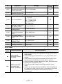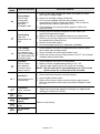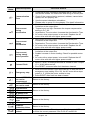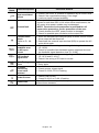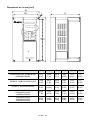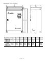
1
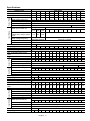
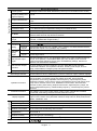
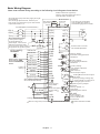
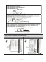
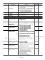
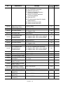
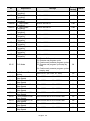
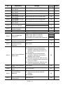
Preface
Thank you for choosing DELTA’s high-performance VFD-B Series. The VFD-B Series is
manufactured with high-quality components and materials and incorporates the latest microprocessor
technology available.
Getting Started
This quick start will be helpful in the installation and parameter setting of the AC motor drives. To
guarantee safe operation of the equipment, read the following safety guidelines before
connecting power to the AC motor drives. For detail information, refer to the VFD-B User Manual
on the CD supplied with the drive.
DANGER!
1.
2.
3.
4.
5.
6.
7.
AC input power must be disconnected before any wiring to the AC motor drive is made.
A charge may still remain in the DC-link capacitors with hazardous voltages, even if the power has
been turned off. To prevent personal injury, please ensure that power has been turned off before
opening the AC motor drive and wait ten minutes for the capacitors to discharge to safe voltage levels.
Never reassemble internal components or wiring.
The AC motor drive may be destroyed beyond repair if incorrect cables are connected to the
input/output terminals. Never connect the AC motor drive output terminals U/T1, V/T2, and W/T3
directly to the AC mains circuit power supply.
Ground the VFD-B using the ground terminal. The grounding method must comply with the laws of the
country where the AC motor drive is to be installed. Refer to the Basic Wiring Diagram.
VFD-B series is used only to control variable speed of 3-phase induction motors, NOT for 1-phase
motors or other purpose.
VFD-B series shall NOT be used for life support equipment or any life safety situation.
WARNING!
1.
2.
3.
DO NOT use Hi-pot test for internal components. The semi-conductor used in the AC motor drive is
easily damaged by high-pressure.
There are highly sensitive MOS components on the printed circuit boards. These components are
especially sensitive to static electricity. To prevent damage to these components, do not touch these
components or the circuit boards with metal objects or your bare hands.
Only quality person is allowed to install, wire and maintain AC motor drive.
CAUTION!
1.
2.
3.
4.
5.
6.
Some parameter settings will cause the motor to run immediately after applying power.
DO NOT install the AC motor drive in a place subjected to high temperature, direct sunlight, high
humidity, excessive vibration, corrosive gases or liquids, or airborne dust or metallic particles.
Only use AC motor drives within specification. Failure to comply may result in fire, explosion or electric
shock.
To prevent personal injury, please keep children and unqualified people away from the equipment.
When the motor cable between the AC motor drive and motor is too long, the layer insulation of the
motor may be damaged. Please use a frequency inverter duty motor or add an AC output reactor to
prevent damage to the motor. Refer to appendix B Reactor for details.
The rated voltage for the AC motor drive must be ≤240V (≤480V for 460V models, ≤600V for 575V
models) and the mains supply current capacity must be ≤5000A RMS (≤10000A RMS for the ≥40hp
(30kW) models).
English- 1
Specifications
300 370
30
37
40
50
45.7 55.0
120 145
1-9
110
142
36
36
Input Rating
Output Rating
Voltage Class
230V Class
Model Number VFD-XXXB
007 015 022 037 055 075 110 150 185 220
Max. Applicable Motor Output (kW) 0.75 1.5
2.2
3.7
5.5
7.5
11
15 18.5 22
Max. Applicable Motor Output (hp)
1.0
2.0
3.0
5.0
7.5
10
15
20
25
30
Rated Output Capacity (kVA) 1.9
2.5
4.2
6.5
9.5 12.5 18.3 24.7 28.6 34.3
Rated Output Current (A)
5.0
7.0
11
17
25
33
49
65
75
90
Maximum Output Voltage (V)
3-Phase Proportional to Input Voltage
Output Frequency (Hz)
0.1~400 Hz
Carrier Frequency (kHz)
1-15
Single/3-phase
3-phase
Rated Input Current (A)
11.9/ 15.3/ 22/
20.6 26
34
50
60
75
90
5.7
7.6 15.5
Input Current for 1-phase
7.0
9.4 14.0
-models when using 3-phase
power
Single/3-phase
3-phase
Rated Voltage/Frequency
200-240V,50/60Hz
200-240V, 50/60Hz
±10%(180~264
V)
Voltage Tolerance
Frequency Tolerance
±5%(47~63 Hz)
Natural
Cooling Method
Fan Cooled
Weight (kg)
2.7
3.2
4.5
6.8
8
10
13
13
13
13
Input Rating Output Rating
Voltage Class
Model Number VFD-XXXB
Max. Applicable Motor Output
(kW)
Max. Applicable Motor Output (hp)
Rated Output Capacity (kVA)
Rated Output Current (A)
Maximum Output Voltage (V)
Output Frequency (Hz)
Carrier Frequency (kHz)
Rated Input Current (A)
Rated Voltage
Voltage Tolerance
Frequency Tolerance
Cooling Method
Weight (kg)
460V Class
007 015 022 037 055 075 110 150 185 220 300 370 450 550 750
0.75 1.5 2.2 3.7
1.0
2.3
2.7
5.5
7.5
11
15 18.5 22
30
37
2.0 3.0 5.0
3.2 4.2 6.5
4.2 5.5 8.5
7.5 10 15 20 25 30 40 50
9.9 13.7 18.3 24.4 28.9 34.3 45.7 55.6
13 18 24 32 38 45 60 73
3-phase Proportional to Input Voltage
0.1~400 Hz
1-15
1-9
3-phase
3.2 4.3 5.9 11.2 14 19 25 32 39 49 60 63
3-phase 380 to 480 V
±10%(342~528 V)
±5%(47~63 Hz)
Natural
Fan Cooled
2.7 3.2 4.5 6.8 8
10 13 13 13 13 36 36
45
55
75
60 75 100
69.3 84 114
91 110 150
1-6
90
130 160
36
50
50
575V Class
007 015 022 037 055 075 110 150 185 220 300 370 450 550 750
0.75 1.5 2.2
3.7
1.0 2.0 3.0
1.7 3.5 4.5
1.7 3.5 4.5
5.0
7.5
7.5
1.2 3.1
Natural
2.7 3.2
5.5
7.5
11
15 18.5 22
30
7.5 10 15 20 25 30 40
10 13.4 18.9 21.9 26.9 33.9 40.8
10 13.5 19 22 27 34 41
3-phase Proportional to Input Voltage
0.1~400 Hz
1-10
1-8
3-phase
4.0 8.3 10.3 13.8 18.2 22 27.7 32 41
3-phase 500 to 600 V
-15~+10% (425~660V)
±5% (47~63Hz)
Fan Cooled
4.5 6.8 8
10 13 13 13 13 36
English- 2
37
45
55
75
50 60 75 100
51.8 61.7 79.7 99.6
52 62 80 100
1-6
52
62
74
91
36
36
50
50
Control Characteristics
Control System
The Resolution of
Frequency Setting and
Output Frequency
0.01Hz
Torque Characteristics
Including the auto-torque, auto-slip compensation; starting torque can be 150% at
1.0Hz
Overload Endurance
150% of rated current for 1 minute
Skip Frequency
Three zones, settings range 0.1-400Hz
Accel/Decel Time
0.1 to 3600 seconds (4 Independent settings for Accel/Decel time)
Stall Prevention Level
Operation frequency 0.1-400.0Hz, output 0-100% rated current
Start time 0-60 seconds, stop time 0-60 seconds
Regenerated Brake
Torque
Approx. 20%(up to 125% possible with option brake resistor or brake unit externally
mounted, 1-15HP brake chopper built-in)
Frequency
Setting
Operating Characteristics
20 to 250%, setting of rated current
DC Brake
V/f Pattern
Operation
Setting
Signal
Adjustable V/f pattern, 1.5 power curve, 1.7 power curve, square and cube curve
Keypad
Setting by
External
Signal
Potentiometer-5kΩ/0.5W, 0 to +10VDC; -10 to +10VDC, 4 to 20mA RS-485 interface;
Multi-Function Inputs 1 to 6 (15 steps, Jog, up/down)
Keypad
Set by RUN, STOP and JOG
External
Signal
2 wires/3 wires (Fwd, Rev, EF), JOG operation, RS-485 serial interface (MODBUS),
process logic control
Multi-Function Input
Signal
Multi-step selection 0 to 15, Jog, accel/decel inhibit, first to forth accel/decel switches,
counter, PLC operation, external Base Block (NC, NO), auxiliary motor control is
invalid, ACI/AVI/AUI selections, driver reset, UP/DOWN key settings, sink/source
selection and reel diameter initialization
Multi-Function Output
Indication
AC drive operating, frequency attained, non-zero, Base Block, fault indication,
local/remote indication, PLC operation indication, auxiliary motor output, driver is
ready, overheat alarm, emergency stop and signal loss alarm
Analog Output Signal
Output frequency/current/voltage/frequency command/speed/factor
Alarm Output Contact
Contact will be On when it malfunctions (1 Form C contact or 3 open collector outputs)
Operation Functions
AVR, accel/decel S-Curve, over-voltage/over-current stall prevention, fault records,
reverse inhibition, momentary power loss restart, DC brake, auto torque/slip
compensation, auto tuning, adjustable carrier frequency, output frequency limits,
parameter lock/reset, vector control, counter, PG feedback control, PID control, fan &
pump control, external counter, PLC, MODBUS communication, abnormal reset,
abnormal re-start, power-saving, sleep/revival function, digital frequency output, fan
control, sleep/wake frequency, master/auxiliary frequency, 1st/2nd frequency source
selections
Protection Functions
Over voltage, over current, under voltage, under current, external fault, overload,
ground fault, overheating, electronic thermal, IGBT short circuit
Display Keypads
Environmental Conditions
General Specifications
SPWM(Sinusoidal Pulse Width Modulation) control (V/f or sensorless vector control)
8-key, 7-segment LED with 5-digit, 8 status LEDs, master frequency, output frequency,
output current, custom units, parameter values for setup and lock, faults, RUN, STOP,
RESET, FWD/REV, JOG
Enclosure Rating
IP20
Pollution Degree
2
Installation Location
Altitude 1,000 m or lower, keep from corrosive gasses, liquid and dust
Ambient Temperature
-10oC to 40oC Non-Condensing and not frozen
Storage/ Transportation
-20 oC to 60 oC
Temperature
Ambient Humidity
Below 90% RH (non-condensing)
Vibration
9.80665m/s2 (1G) less than 20Hz, 5.88m/s2 (0.6G) at 20 to 50Hz
Approvals
English- 3
Basic Wiring Diagram
Users must connect wiring according to the following circuit diagram shown below.
Br ak e r es itor /uni t (optional)
R efer to us er manual for the use of
special brake resi stor/uni t.
* T hree phase input power may apply to single
phase drives .
* For the single phas e driv es, the AC input
li ne can be connected to any two of the three
input termi nal s R , S , T.
+1 +2/B1
F us e/NF B(None F use Br eaker)
R(L1)
S( L2)
R(L1)
S(L2)
T(L3)
E
T(L3)
Recommended C irc ui t
w hen pow er suppl y
is turned O FF by a
fault output. T he contact
will be On w hen the faul t
occur s to tuen off the pow er
and pr otect the power sy stem.
SA
MC
ON
OF F
F act ory Settin g:
SINK Mo de
F WD/ST OP
Sw1
JO G
Source
Please refer to F ig u re 4
fo r w irin g of S INK
m od e an d SOURCE
m od e.
F ac tor y
setting
E.F.
Multi-s tep 1
Multi-s tep 2
Multi-s tep 3
Multi-s tep 4
RESET
Acc el/Decel prohibit
Counter
Digital Si gnal Common
* Don't apply voltage to
above ter minals directly .
5K
IM
3~
V(T2)
W(T 3)
E
RB
RA
RB
+24V
FWD
REV
JOG
EF
MI1
MI2
MI3
MI4
MI5
MI6
TRG
DCM
E
+10V
Please refer to control
Ter minal Ex planation.
RC
MO1
F ac tor y setting:
indicates during operation
48V50mA
MO2
F ac tor y setting:
F req. Setting Indication
48V50mA
MO3
F ac tor y setting:
Low -voltage Indication
48V50mA
Multi-function
Photocoulper Output
MCM
AFM
Analog Multi- func tion Output
Ter minal
F ac tor y setting: Analog freq.
/ c ur rent meter 0~1 0VDC/2 mA
Analog S ignal common
ACM
E
DFM
D igital F requency Output
Ter minal
F ac tor y default: 1:1
D uty =50%
D igital Si gnal C ommon
AVI
2
1
Motor
U(T1)
Power supply
+10V 20m A
3
T he w iring for the models
may be differ ent. Refer to
the follow ing figures for detail.
B2
RC
MC
REV/STO P
Sink
Br ak e r es istor
(optional)
D C reac tor
(optional)
Jumper
4~20mA
-10~+10V
Analog S ignal Common
Master Fr equency
0 to 10V 47k
ACI
AUI
ACM
E
Main c irc ui t (power) terminals
English- 4
DCM
RS-485
Seri al interface
1: EV 2: G ND 3: SG4: SG + 5:R eserv ed
6: R eserv ed
Contr ol c ircuit ter minals
Shield ed leads & c able
F igure 1 for models of VFD -B Series
V FD007B21A/23A/ 4 3A/ 53A ,
V FD015B21A/21B/ 2 3A/ 23B /43A /53A,
V FD022B23B/43B/ 5 3A
Brake r esistor
(option al)
DC c hoke
(optional)
Jumpe r
+1 +2/B1
B2
Figure 2 for models of VFD-B Series
VFD022B21A, VFD037B23A/43A/53A, VFD055B23A/43A/53A,
VFD075B23A/43A/53A, VFD110B23A/43A/53A
DC chock
(optional)
Jumper
brake resistor(BR) is optional
BR
+1
+2/B1
B2
-( min us sig n)
Figure 3 for models of VFD-B Series
VFD150B23A/43A/53A, VFD185B23A/43A/53A, VFD220B23A/43A/53A,
VFD300B23A/43A/53A, VFD370B23A/43A/53A, VFD450B43A/53A,
VFD550B43C/53A, VFD750B43C/53A
Brake unit/brake resistor(optional)
DC chock
(optional)
VF DB
Jumper
+2
+1
-( min us sig n)
Figure 4 Wiring for SINK mode and SOURCE mode
A. SINK mode
B. SOURCE mode
F WD /S TOP
Sink
R EV/STO P
SW1
JO G
Sourc e
E.F.
Multi-s tep1
Multi-s tep2
Factory
setting
Multi-s tep3
Multi-s tep4
RESET
Acc el./D ecel. pr ohibit
Counter
D igital Si gnal Common
*D on't appl y the mains voltage
dir ectly to abov e terminals .
+24V
FWD
REV
JOG
EF
MI1
MI2
MI3
MI4
MI5
MI6
TRG
DCM
E
English- 5
F WD/S TOP
Sink
REV/STO P
SW1
JO G
Sourc e
E.F.
Multi-s tep1
Multi-s tep2
Factory
setting
Multi-s tep3
Multi-s tep4
RESET
Acc el./D ecel. pr ohibit
Counter
*D on't appl y the mains voltage
dir ectly to abov e terminals .
+24V
FWD
REV
JOG
EF
MI1
MI2
MI3
MI4
MI5
MI6
TRG
DCM
E
Description of the Digital Keypad
The digital keypad includes two parts: Display panel and keypad. The display panel provides the
parameter display and shows the operation status of the AC drive and the keypad provides
programming and control interface.
F
H
U
LED Display
Display frequency, current, voltage
and error, etc.
VFD-PU01
Part Number
Status Display
Display of drive status
JOG
Jog operation selector
MODE
Display mode selector
JOG
Left key
Moves cursor to the left
STOP/RESET
UP and DOWN Key
Sets the parameter
number and changes the
numerical data, such as
Master Frequency.
STOP
RESET
RUN
RUN key
Operation Steps of the Digital Keypad
Se lecti on m ode
START
F
H
U
F
H
U
MO DE
MO DE
F
H
U
F
H
U
PROG
NOTE: I n th e s election mo de, press DATA
F
H
U
MO DE
MO DE
MO DE
GO START
to set t he p aramet ers.
To set par am eter s
F
H
U
F
H
U
PROG
DATA
F
H
U
F
H
U
PROG
DATA
PROG
DATA
para meter set s uccessfully
F
H
U
para meter set error
MO DE
mov e t o pre vious d is play
NOTE: I n th e para meter se tting mode, you c an press
MO DE
to retu rn to the selec tion mo de.
To shift cursor
START
F
H
U
F
H
U
F
H
U
English- 6
F
H
U
F
H
U
To modify data
F
H
U
START
F
H
U
F
H
U
F
H
U
F
H
U
To set di re ction
F
H
U
or
or
Power Terminals and Control Terminals
1HP to 3HP (0.75 to 2.2kW) VFD007B21A/23A/43A/53A, VFD015B21A/21B//23A/23B/43A/53A,
VFD022B23B/43B/53A
Control Terminal
Torque: 4Kgf-cm (3 in-lbf)
Wire: 12-24 AWG (3.3-0.2 mm2)
Power Terminal
Torque: 18 kgf-cm (15.6 in-lbf)
Wire Gauge: 10-18 AWG (5.3-0.8 mm2) stranded
wire, 12-18 AWG (3.3-0.8 mm2) solid wire
Wire Type: Copper only, 75°C
S
T
R
/L1 /L2 /L3
+1
+2
/B1
B2
V
U
W
/T1 / T2 /T3
English- 7
3HP to 5HP (2.2 to 3.7kW) VFD022B21A, VFD037B23A/43A/53A
Control Terminal
Torque: 4Kgf-cm (3 in-lbf)
Wire: 12-24 AWG (3.3-0.2mm2)
Power Terminal
Torque: 18 kgf-cm (15.6 in-lbf)
Wire Gauge: 10-18 AWG (5.3-0.8mm2)
Wire Type: Stranded copper only, 75°C
+1 +2 B1 -
B2
U/T1 V/T2 W/T3
Screw Torque :
18Kgf-cm
Wire Gauge :
18~10AWG
R/L1 S/L2 T/L3
7.5 HP to 15 HP (5.5kW to 11kW) VFD055B23A/43A/53A, VFD075B23A/43A/53A,
VFD110B23A/43A/53A
Control Terminal
Torque: 4Kgf-cm (3 in-lbf)
Wire: 12-24 AWG (3.3-0.2mm2)
Power Terminal
Torque: 30Kgf-cm (26 in-lbf)
Wire: 8-12 AWG (8.4-3.3mm2)
Wire Type: Stranded Copper only, 75°C
NOTE: To connect 6 AWG (13.3 mm2) wires, use
Recognized Ring Terminals
POWER
IM
3
MOTOR
English- 8
20 HP to 30 HP (15kW to 22kW) VFD150B23A/43A/53A, VFD185B23A/43A/53A,
VFD220B23A/43A/53A
Control Terminal
Torque: 4Kgf-cm (3 in-lbf)
Wire: 12-24 AWG (3.3-0.2 mm2)
Power Terminal
Torque: 30Kgf-cm (26 in-lbf)
Wire: 2-8 AWG (33.6-8.4 mm2)
Wire Type: Stranded Copper only, 75°C
NOTE: To connect 6 AWG (13.3 mm2) wires, use
Recognized Ring Terminals
R/L1 S/L2 T/L3 +1
POWER
+2
DC (+)
-
DC ( - )
V/T2 W/T3
IM
3
MOTOR
40 HP to 50 HP (30 to 37kW) 230V (VFD300B23A, VFD370B23A)
75 HP to 100 HP (55 to 75kW) 460V (VFD550B43C, VFD750B43C)
75 HP to 100 HP (55 to 75kW) 575V (VFD550B53A, VFD750B53A)
POWER
ALARM
Control Terminal
Torque: 4Kgf-cm (3 in-lbf)
Wire: 12-24 AWG (3.3-0.2 mm2)
CHARGE
Power Terminal
Torque: 200kgf-cm (173 in-lbf)
Wire Gauge: 1 - 3/0 AWG (42.4-85 mm2)
Wire Type: Stranded copper only, 75°C
R/L1 S/L2 T/L3
POWER
+1
+2
Screw Torque:
200kgf-cm (173in-lbf)
U/T1 V/T2 W/T3
IM
3
MOTOR
English- 9
40 HP to 60 HP (30 to 45kW) 460V (VFD300B43A, VFD370B43A, VFD450B43A)
40 HP to 60 HP (30 to 45kW) 575V (VFD300B53A, VFD370B53A, VFD450B53A)
POWER
ALARM
Control Terminal
Torque: 4Kgf-cm (3 in-lbf)
Wire: 12-24 AWG (3.3-0.2 mm2)
CHARGE
Power Terminal
Torque: 58.7kgf-cm (50.9 in-lbf) max.
Wire Gauge: 2-6AWG (33.6-13.3 mm2)
Wire Type: Stranded copper only, 75°C
+1
R/L1 S/L2 T/L3
+2
-
U/T1 V/T2 2/T3
IM
3
POWER
MOTOR
Terminal Explanations
Terminal Symbol
R, S, T
R/L1, S/L2, T/L3
U, V, W
U/T1, V/T2, W/T3
P1, P2
P-B, P2/B1~B2
+1, +2
+2/B1~B2
P2~N, P2/B1~N
+2~(-), +2/B1~(-)
Explanation of Terminal Function
AC line input terminals (1-phase/3-phase)
AC drive output terminals for connecting 3-phase
induction motor
Connections for DC Choke (optional)
Connections for Brake Resistor (optional)
Connections for External Brake Unit (VFDB series)
Earth connection, please comply with local regulations.
Control Terminals Explanations
Terminal
Symbol
Terminal Function
FWD
Forward-Stop command
ON: Run in FWD direction, OFF: Stop acc. to Stop Method
REV
Reverse-Stop command
ON: Run in REV direction, OFF: Stop acc. to Stop Method
JOG
Jog command
ON: JOG operation, OFF: Stop acc. to Stop Method
External fault
ON: External Fault. Display “EF” and stop acc. To Stop
Method.
OFF: No fault
TRG
External counter input
ON: At every pulse counter is advanced by 1.
MI1-6
Multi-function Input 1-6
Refer to Pr.04-04 to Pr.04-09 for programming the Multifunction Inputs.
EF
Factory Settings (SINK)
ON: Connect to DCM
English- 10
Terminal
Symbol
Factory Settings (SINK)
ON: Connect to DCM
Terminal Function
Digital Frequency Meter
(Open Collector Output)
DFM-DCM
DFM
Max: 48V
50mA
50%
100%
Internal Circuit
Pulse voltage output monitor signal, proportional to output
frequency
Duty-cycle:
50%
Ratio:
Pr.03-07
Min. load:
10KΩ
Max. current:
50mA
Max. voltage:
48VDC.
+24V
DC Voltage Source
+24VDC, 20mA: used for SOURCE mode
DCM
Digital Signal Common
Common for digital inputs and used for SINK mode.
Multi-function Relay
output (N.O.) a
Multi-function Relay
output (N.C.) b
Multi-function Relay
common
Resistive Load: 5A(N.O.)/3A(N.C.) 240VAC
5A(N.O.)/3A(N.C.) 24VDC
Inductive Load: 1.5A(N.O.)/0.5A(N.C.) 240VAC
1.5A(N.O.)/0.5A(N.C.) 24VDC
Refer to Pr.03-00 for programming
MO1
Multi-function Output 1
(Photocoupler)
Maximum 48VDC, 50mA
Refer to Pr.03-01 to Pr.03-03 for programming
MO2
Multi-function Output 2
(Photocoupler)
MO3
Multi-function Output 3
(Photocoupler)
MCM
Multi-function output
common
Common for Multi-function Outputs
+10V
Potentiometer power
supply
+10VDC 20mA
RA
RB
RC
MO1~MO3-DCM
Max: 48Vdc
50mA
MO1~MO3
MCM
Internal Circuit
Analog voltage Input
+10V
AVI circuit
AVI
AVI
Impedance:
47kΩ
Resolution:
10 bits
Range: 0 ~10VDC = 0 ~ Max. Output Frequency (Pr.01-00)
Selection: Pr.02-00, Pr.02-13, Pr.10-00
Set-up:
Pr.04-00 ~ Pr.04-03
ACM Internal Circuit
Analog current Input
ACI
ACI circuit
ACI
Impedance:
250Ω
Resolution:
10 bits
Range: 4 ~ 20mA =0 ~ Max. Output Frequency (Pr.01-00)
Selection: Pr.02-00, Pr.02-13, Pr.10-00
Set-up:
Pr.04-11 ~ Pr.04-14
ACM Internal Circuit
English- 11
Terminal
Symbol
Factory Settings (SINK)
ON: Connect to DCM
Terminal Function
Auxiliary analog voltage
input
+10~-10V
AUI circuit
Impedance:
47kΩ
Resolution:
10 bits
Range:-10 ~ +10VDC=0~Max. Output Frequency(Pr.01-00)
Selection:
Pr.02-00, Pr.02-13, Pr.10-00
Set-up:
Pr.04-15 ~ Pr.04-18
AUI
AUI
ACM Internal Circuit
Analog output meter
ACM circuit
AFM
Internal Circuit
ACM
0 to 10V, 2mA
Impedance:
Output current
Resolution:
Range:
Function:
0~10V
ondometer
AFM Max. 2mA
ACM
Analog control signal
(common)
470Ω
2mA max
8 bits
0 ~ 10VDC
Pr.03-05
Common for AVI, ACI, AUI, AFM
**Control signal wiring size: 18 AWG (0.75 mm2) with shielded wire.
Summary of Parameter Settings
a: The parameter can be set during operation.
Pr.
Explanation
00-00
Identity Code of the AC
motor drive
00-01
Rated Current Display
of the AC motor drive
00-02
a00-03
Settings
Group 0 User Parameters
Read-only
Factory
Setting
##
Read-only
#.#
Parameter Reset
08: Keypad lock
09: All parameters are reset to factory
settings (50Hz, 220V/380V/575V)
10: All parameters are reset to factory
settings (60Hz, 220V/440V/575V)
00
Start-up Display
Selection
00: Display the frequency command
value (LED F)
01: Display the actual output frequency
(LED H)
02: Display the content of user-defined
unit (LED U)
03: Multifunction display, see Pr.00-04
04: FWD/REV command
00
English- 12
NOTE
Pr.
a00-04
Content of Multi
Function Display
00-06
00-07
00-08
User-Defined
Coefficient K
Software Version
Password Input
Password Set
00-09
Control Method
00-10
Reserved
a00-05
Settings
Factory
Setting
00: Display output current (A)
01: Display counter value (C)
02: Display process operation (1.tt)
03: Display DC-BUS voltage ( u )
04: Display output voltage (E)
05: Output power factor angle (n)
06: Display output power (P)
07: Display actual motor speed (HU)
08: Display the estimated value of torque
as it relates to current (t)
09: Display PG numbers/10ms (G)
10: Display analog feedback signal value
(b) (%)
11: Display AVI (U1.) (%)
12: Display ACI (U2.) (%)
13: Display AUI (U3.) (%)
14: Display the temperature of heat sink
(°C)
00
Explanation
0.01 to 160.00
1.00
Read-only
00 to 65535
00 to 65535
00: V/f Control
01: V/f + PG Control
02: Vector Control
03: Vector + PG Control
#.##
00
00
00
Group 1 Basic Parameters
01-00
01-01
Maximum Output
Frequency (Fmax)
Maximum Voltage
Frequency (Fbase)
50.00 to 400.00 Hz
60.00
0.10 to 400.00 Hz
60.00
220.0
440.0
575.0
01-02
Maximum Output
Voltage (Vmax)
230V series: 0.1V to 255.0V
460V series: 0.1V to 510.0V
575V series: 0.1V to 637.0V
01-03
Mid-Point Frequency
(Fmid)
0.10 to 400.00 Hz
0.50
01-04
Mid-Point Voltage
(Vmid)
230V series: 0.1V to 255.0V
460V series: 0.1V to 510.0V
575V series: 0.1V to 637.0V
1.7
3.4
4.8
01-05
Minimum Output
Frequency (Fmin)
0.10 to 400.00 Hz
0.50
Minimum Output
Voltage (Vmin)
230V series: 0.1V to 255.0V
460V series: 0.1V to 510.0V
575V series: 0.1V to 637.0V
1.7
3.4
4.8
01-06
01-07
01-08
Output Frequency
Upper Limit
Output Frequency
Lower Limit
1 to 120%
0 to100 %
English- 13
100
0
NOTE
Pr.
a01-09
a01-10
a01-11
a01-12
a01-13
a01-14
a01-15
Factory
Setting
Accel Time 1
0.01 to 3600.0 sec
10.0
Decel Time 1
0.01 to 3600.0 sec
10.0
Accel Time 2
0.01 to 3600.0 sec
10.0
Decel Time 2
0.01 to 3600.0 sec
10.0
01-09 ~ 01-12: Factory setting for models of 30hp (22kW) and above is 60sec.
Jog Acceleration Time
0.1 to 3600.0 sec
1.0
Jog Frequency
0.10 Hz to 400.00 Hz
6.00
00: Linear Accel/Decel
01: Auto Accel, Linear Decel
Auto acceleration /
02: Linear Accel, Auto Decel
deceleration (refer to
00
03: Auto Accel/Decel (Set by load)
Accel/Decel time
04: Auto Accel/Decel (set by Accel/Decel
setting)
Time setting)
Explanation
Settings
01-16
01-17
a01-18
a01-19
a01-20
a01-21
Acceleration S-Curve
00 to 07
00
Deceleration S-Curve
00 to 07
00
Accel Time 3
0.01 to 3600.0 sec
10.0
Decel Time 3
0.01 to 3600.0 sec
10.0
Accel Time 4
0.01 to 3600.0 sec
10.0
Decel Time 4
0.01 to 3600.0 sec
10.0
01-18 ~ 01-21: Factory setting for models of 30hp (22kW) and above is 60sec.
a01-22 Jog Deceleration Time
0.1 to 3600.0 sec
1.0
00: Unit: 1 sec
01: Unit: 0.1 sec
01-23
Accel/Decel Time Unit
01
02: Unit: 0.01 sec
a02-00
a02-01
Group 2 Operation Method Parameters
00: Digital keypad (PU01) UP/DOWN
keys or Multi-function Inputs
UP/DOWN. Last used frequency
saved.
01: 0 to +10V from AVI
02: 4 to 20mA from ACI
03: -10 to +10Vdc from AUI
Source of First Master
04: RS-485 serial communication (RJFrequency Command
11). Last used frequency saved.
05: RS-485 serial communication (RJ11). Last used frequency not saved.
06: Combined use of master and auxiliary
frequency command
(See Pr. 02-10 to 02-12)
00: Digital keypad (PU01)
01: External terminals. Keypad
STOP/RESET enabled.
02: External terminals. Keypad
Source of First
STOP/RESET disabled.
Operation Command
03: RS-485 serial communication (RJ11). Keypad STOP/RESET enabled.
04: RS-485 serial communication (RJ11). Keypad STOP/RESET disabled.
English- 14
00
00
NOTE
Pr.
02-02
02-03
02-04
02-05
02-06
02-07
Explanation
Stop Method
Settings
00: STOP: ramp to stop; E.F.: coast to
stop
01: STOP: coast to stop; E.F.: coast to
stop
02: STOP: ramp to stop; E.F.: ramp to
stop
03: STOP: coast to stop; E.F.: ramp to
stop
230V&460V:1-5hp/0.75-3.7kW: 1-15kHz
7.5-25hp/5.5-18.5kW: 01-15kHz
30-60hp/22-45kW: 01-09kHz
PWM Carrier Frequency
75-100hp/55-75kW: 01-06kHz
Selections
575V: 1-15hp/0.75-11kW: 01-10 kHz
20-60hp/15-45kW: 01-08 kHz
75-100hp/55-75kW: 01-06kHz
00: Enable forward/reverse operation
Motor Direction Control 01: Disable reverse operation
02: Disabled forward operation
2-wire/3-wire Operation
Control Modes
Line Start Lockout
Loss of ACI Signal (420mA)
00: 2-wire: FWD/STOP, REV/STOP
01: 2-wire: FWD/REV, RUN/STOP
02: 3-wire operation
00: Disable. Operation status is not
changed even if operation command
source Pr.02-01 and/or Pr.02-14 is
changed.
01: Enable. Operation status is not
changed even if operation command
source Pr.02-01 and/or Pr.02-14 is
changed.
02: Disable. Operation status will change
if operation command source Pr.0201 and/or Pr.02-14 is changed.
03: Enable. Operation status will change
if operation command source Pr.0201 and/or Pr.02-14 is changed.
00: Decelerate to 0 Hz
01: Coast to stop and display “EF”
02: Continue operation by last frequency
command
00: Based on accel/decel time
01: Constant speed
02: Based on accel/decel time, but
frequency command will be 0 when
stopped.
a02-08
Up/Down Mode
a02-09
Accel/Decel Rate of
Change of UP/DOWN
0.01~1.00 Hz/msec
Operation with Constant
Speed
English- 15
Factory
Setting
00
15
09
06
06
06
06
06
00
00
00
00
00
0.01
NOTE
Pr.
Explanation
Settings
Factory
Setting
Source of the Master
Frequency Command
00: Digital keypad (PU01) UP/DOWN
keys or Multi-function Inputs
UP/DOWN. Last used frequency
saved.
01: 0 to +10V from AVI
02: 4 to 20mA from ACI
03: -10 to +10Vdc from AUI
04: RS-485 serial communication (RJ11). Last used frequency saved.
00
a02-11
Source of the Auxiliary
Frequency Command
00: Digital keypad (PU01) UP/DOWN
keys or Multi-function Inputs
UP/DOWN. Last used frequency
saved.
01: 0 to +10V from AVI
02: 4 to 20mA from ACI
03: -10 to +10Vdc from AUI
04: RS-485 serial communication (RJ11). Last used frequency saved.
00
a02-12
Combination of the
Master and Auxiliary
Frequency Command
00: Master frequency + auxiliary
frequency
01: Master frequency - auxiliary
frequency
00
Source of Second
Frequency Command
00: Digital keypad (PU01) UP/DOWN
keys or Multi-function Inputs
UP/DOWN. Last used frequency
saved.
01: 0 to +10V from AVI
02: 4 to 20mA from ACI
03: -10 to +10Vdc from AUI
04: RS-485 serial communication (RJ11). Last used frequency saved
05: RS-485 serial communication (RJ11). Last used frequency not saved.
06: Combined use of master and auxiliary
frequency command (See Pr. 02-10 to
02-12)
00
Source of Second
Operation Command
00: Digital keypad (PU01)
01: External terminals. Keypad
STOP/RESET enabled.
02: External terminals. Keypad
STOP/RESET disabled.
03: RS-485 serial communication (RJ11). Keypad STOP/RESET enabled.
04: RS-485 serial communication (RJ11). Keypad STOP/RESET disabled.
00
a02-10
a02-13
a02-14
a02-15
03-00
Keypad Frequency
0.00 ~ 400.00Hz
Command
Group 3 Output Function Parameters
Multi-Function Output
00: No function
Relay (RA1, RB1, RC1) 01: AC drive operational
English- 16
60.00
08
NOTE
Pr.
Explanation
03-01
Multi-Function Output
Terminal MO1
03-02
Multi-Function Output
Terminal MO2
03-03
03-04
03-05
a03-06
a03-07
a03-08
a03-09
03-10
03-11
Multi-Function Output
Terminal MO3
Desired Frequency
Attained 1
Analog Output Signal
Analog Output Gain
Digital Output
Multiplying Factor
Terminal Count Value
Preliminary Count Value
Desired Frequency
Attained 2
Settings
02: Master frequency attained
03: Zero speed
04: Over torque detection
05: Base-Block (B.B.) indication
06: Low-voltage indication
07: Operation mode indication
08: Fault indication
09: Desired frequency attained 1
10: PLC program running
11: PLC program step completed
12: PLC program completed
13: PLC program operation paused
14: Terminal count value attained
15: Preliminary count value attained
16: Auxiliary motor No.1
17: Auxiliary motor No.2
18: Auxiliary motor No.3
19: Heat sink overheat warning
20: AC motor drive ready
21: Emergency stop indication
22: Desired frequency attained 2
23: Software brake signal
24: Zero speed output signal
25: Under-current detection
26: Operation indication (H>=Fmin)
27: Feedback signal error
28: User-defined low-voltage detection
29: Brake control (Desired frequency
attained 3)
0.00 to 400.00 Hz
Factory
Setting
01
02
20
0.00
00: Analog frequency meter
01: Analog current meter
02: Output voltage
03: Output frequency command
04: Output motor speed
05: Load power factor (cos90o to Cos0o)
00
01 to 200%
01 to 20
100
01
00 to 65500
00 to 65500
00
00
0.00 to 400.00 Hz
00: Preliminary count value attained, no
EF Active When
EF display
Preliminary Count Value
01: Preliminary count value attained, EF
Attained
active
English- 17
0.00
00
NOTE
Pr.
03-12
03-13
03-14
a04-00
04-01
a04-02
04-03
Settings
Factory
Setting
00: Fan always ON
01: 1 minute after AC motor drive stops,
fan will be OFF
02: AC motor drive runs and fan ON, AC
motor drive stops and fan OFF
03: Fan ON to run when preliminary
heatsink temperature attained
00
Explanation
Fan Control
Brake Release
Frequency
Brake Engage
Frequency
0.00 to 400.00Hz
0.00
0.00 to 400.00Hz
0.00
Group 4 Input Function Parameters
AVI Analog Input Bias
0.00~200.00 %
00: Positive bias
AVI Bias Polarity
01: Negative bias
AVI Input Gain
AVI Negative Bias,
Reverse Motion
Enable/Disable
04-04
Multi-Function Input
Terminal 1 (MI1)
04-05
Multi-Function Input
Terminal 2 (MI2)
04-06
Multi-Function Input
Terminal 3 (MI3)
04-07
Multi-Function Input
Terminal 4 (MI4)
04-08
Multi-Function Input
Terminal 5 (MI5)
04-09
Multi-Function Input
Terminal 6 (MI6)
1 to 200 %
00: No AVI negative bias command
01: Negative bias: REV motion enabled
02: Negative bias: REV motion disabled
00: No function
01: Multi-Step speed command 1
02: Multi-Step speed command 2
03: Multi-Step speed command 3
04: Multi-Step speed command 4
05: External reset (N.O.)
06: Accel/Decel inhibit
07: Accel/Decel time selection command
1
08: Accel/Decel time selection command
2
09: External base block (N.O.)
10: External base block (N.C.)
11: Up: Increment master frequency
12: Down: Decrement master frequency
13: Counter reset
14: Run PLC program
15: Pause PLC program
16: Auxiliary motor No.1 output disable
17: Auxiliary motor No.2 output disable
18: Auxiliary motor No.3 output disable
19: Emergency stop (N.O.)
20: Emergency stop (N.C.)
21: Master frequency selection AVI/ACI
22: Master frequency selection AVI/AUI
23: Operation command selection
(keypad/external terminals)
24: Auto accel/decel mode disable
25: Forced stop (N.C.)
26: Forced stop (N.O.)
27: Parameter lock enable (N.O.)
English- 18
0.00
00
100
00
01
02
03
04
05
06
NOTE
Pr.
Explanation
Settings
Factory
Setting
28: PID function disabled
29: Jog FWD/REV command
30: External reset (N.C.)
31: Source of second frequency
command enabled
32: Source of second operation
command enabled
33: One shot PLC
34: Proximity sensor input for simple
Index function
35: Output shutoff stop (NO)
36: Output shutoff stop (NC)
04-10
a04-11
04-12
a04-13
04-14
Digital Terminal Input
Debouncing Time
ACI Analog Input Bias
1 to 20 (*2ms)
ACI Input Gain
ACI Negative Bias,
Reverse Motion
Enable/Disable
00: No ACI negative bias command
01: Negative bias: REV motion enabled
02: Negative bias: REV motion disabled
AUI Analog Input Bias
0.00
0.05
ACI Bias Polarity
04-18
AUI Negative Bias
Reverse Motion
Enable/Disable
0.00~200.00 %
00: Positive bias
01: Negative bias
01 to 200 %
00: No AUI negative bias command
01: Negative bias: REV motion enabled
02: Negative bias: REV motion disabled
04-19
AVI Analog Input Delay
0.00 to 10.00 sec
04-20
04-21
ACI Analog Input Delay 0.00 to 10.00 sec
AUI Analog Input Delay 0.00 to 10.00 sec
Analog Input Frequency 00: 0.01Hz
Resolution
01: 0.1Hz
4 ~ 1000
Gear Ratio for Simple
Index Function
0.0 ~360.0o
Index Angle for Simple
Index Function
0.00 ~100.00 sec
Deceleration Time for
Simple Index Function
Group 5 Multi-Step Speed and PLC Parameters
1st Step Speed
0.00 to 400.00 Hz
Frequency
nd
2 Step Speed
0.00 to 400.00 Hz
Frequency
rd
3 Step Speed
0.00 to 400.00 Hz
Frequency
a04-15
04-16
a04-17
04-22
04-23
04-24
a04-25
a05-00
a05-01
a05-02
01
0.00~200.00 %
00: Positive bias
01: Negative bias
01 to 200 %
AUI Bias Polarity
AUI Input Gain
English- 19
0.00
00
100
00
00
100
00
0.05
0.05
01
200
180.0
0.00
0.00
0.00
0.00
NOTE
Pr.
a05-03
a05-04
a05-05
a05-06
a05-07
a05-08
a05-09
a05-10
a05-11
a05-12
a05-13
a05-14
4 Step Speed
Frequency
5th Step Speed
Frequency
6th Step Speed
Frequency
7th Step Speed
Frequency
8th Step Speed
Frequency
9th Step Speed
Frequency
10th Step Speed
Frequency
11th Step Speed
Frequency
12th Step Speed
Frequency
13th Step Speed
Frequency
14th Step Speed
Frequency
15th Step Speed
Frequency
05-15
PLC Mode
05-16
PLC Forward/ Reverse
Motion
Time Duration of 1st
Step Speed
Time Duration of 2nd
Step Speed
Time Duration of 3rd
Step Speed
Time Duration of 4th
Step Speed
Time Duration of 5th
Step Speed
Time Duration of 6th
Step Speed
Time Duration of 7th
Step Speed
Time Duration of 8th
Step Speed
Time Duration of 9th
Step Speed
05-17
05-18
05-19
05-20
05-21
05-22
05-23
05-24
05-25
0.00 to 400.00 Hz
Factory
Setting
0.00
0.00 to 400.00 Hz
0.00
0.00 to 400.00 Hz
0.00
0.00 to 400.00 Hz
0.00
0.00 to 400.00 Hz
0.00
0.00 to 400.00 Hz
0.00
0.00 to 400.00 Hz
0.00
0.00 to 400.00 Hz
0.00
0.00 to 400.00 Hz
0.00
0.00 to 400.00 Hz
0.00
0.00 to 400.00 Hz
0.00
0.00 to 400.00 Hz
0.00
Explanation
th
Settings
00: Disable PLC operation
01: Execute one program cycle
02: Continuously execute program cycles
03: Execute one program cycle step by
step
04: Continuously execute program cycles
step by step
00
00 to 32767 (00: FWD, 01: REV)
00
00 to 65500 sec or 00 to 6550.0 sec
00
00 to 65500 sec or 00 to 6550.0 sec
00
00 to 65500 sec or 00 to 6550.0 sec
00
00 to 65500 sec or 00 to 6550.0 sec
00
00 to 65500 sec or 00 to 6550.0 sec
00
00 to 65500 sec or 00 to 6550.0 sec
00
00 to 65500 sec or 00 to 6550.0 sec
00
00 to 65500 sec or 00 to 6550.0 sec
00
00 to 65500 sec or 00 to 6550.0 sec
00
English- 20
NOTE
Pr.
05-26
05-27
05-28
05-29
05-30
05-31
05-32
05-33
05-34
06-00
06-01
06-02
06-03
06-04
06-05
06-06
06-07
00 to 65500 sec or 00 to 6550.0 sec
Factory
Setting
00
00 to 65500 sec or 00 to 6550.0 sec
00
00 to 65500 sec or 00 to 6550.0 sec
00
00 to 65500 sec or 00 to 6550.0 sec
00
00 to 65500 sec or 00 to 6550.0 sec
00
00 to 65500 sec or 00 to 6550.0 sec
00
00: 1 sec
01: 0.1 sec
00
Explanation
Time Duration of 10th
Step Speed
Time Duration of 11th
Step Speed
Time Duration of 12th
Step Speed
Time Duration of 13th
Step Speed
Time Duration of 14th
Step Speed
Time Duration of 15th
Step Speed
Time Unit Settings
Settings
The Amplitude of
0.00~400.00 Hz
Wobble Vibration
Wobble Skip Frequency 0.00~400.00 Hz
Group 6 Protection Parameters
230V series: 330.0V to 410.0V
460V series: 660.0V to 820.0V
Over-Voltage Stall
575V series: 825.0V to1025.0V
Prevention
00: Disable over-voltage stall prevention
Over-Current Stall
Prevention during Accel
Over-Current Stall
Prevention during
Operation
Over-Torque Detection
Mode (OL2)
Over-Torque Detection
Level
Over-Torque Detection
Time
Electronic Thermal
Overload Relay
Selection
Electronic Thermal
Characteristic
0.00
0.00
390.0V
780.0V
975.0V
20 to 250%
170
20 to 250%
170
00: Disabled
01: Enabled during constant speed
operation. After the over-torque is
detected, keep running until OL1 or
OL occurs.
02: Enabled during constant speed
operation. After the over-torque is
detected, stop running.
03: Enabled during accel. After the overtorque is detected, keep running until
OL1 or OL occurs.
04: Enabled during accel. After the overtorque is detected, stop running.
00
10 to 200%
150
0.1 to 60.0 sec
0.1
00: Standard motor (self cooled by fan)
01: Special motor (forced external
cooling)
02: Disabled
02
30 to 600 sec
60
English- 21
NOTE
Pr.
06-08
06-09
06-10
06-11
06-12
06-13
Explanation
00: No fault
01: Over current (oc)
Present Fault Record
02: Over voltage (ov)
03: Over heat (oH)
04: Over load (oL)
Second Most Recent
05: Over load (oL1)
Fault Record
06: External fault (EF)
07: IGBT protection (occ)
08: CPU failure (cF3)
09: Hardware protection failure (HPF)
10: Excess current during acceleration
(ocA)
11: Excess current during deceleration
(ocd)
12: Excess current during steady state
(ocn)
Third Most Recent Fault
13: Ground fault (GFF)
Record
14: Reserved
15: CF1
Fourth Most Recent
16: CF2
Fault Record
17: Reserved
18: Motor over-load (oL2)
19: Auto Acel/Decel failure (CFA)
20: SW/Password protection (codE)
21: External Emergency Stop (EF1)
22: Phase-Loss (PHL)
23: Preliminary count value attained, EF
active (cEF)
24: Under-current (Lc)
25: Analog feedback signal error (AnLEr)
26: PG feedback signal error (PGErr)
Under-Current
Detection Level
Under-Current
Detection Time
06-14
Under-Current
Detection Mode
06-15
Under-Current
Detection Restart Delay
Time (Lv)
06-16
User-Defined LowVoltage Detection Level
06-17
06-18
Settings
User-Defined LowVoltage Detection Time
Reserved
00~100% (00: Disabled)
0.1~ 3600.0 sec
00: Warn and keep operating
01: Warn and ramp to stop
02: Warn and coast to stop
03: Warn, after coast to stop, restart
(delay 06-15 setting time)
Factory
Setting
00
00
10.0
00
1~600 Min.
10
00: Disabled
230V: 220 to 300VDC
460V: 440 to 600VDC
575V: 520 to 780VDC
00
0.1~ 3600.0 sec
0.5
English- 22
NOTE
Pr.
a07-00
a07-01
a07-02
a07-03
07-04
07-05
07-06
07-07
07-08
07-09
07-10
07-11
07-12
07-13
07-14
07-15
08-00
08-01
08-02
08-03
08-04
08-05
08-06
08-07
08-08
08-09
Explanation
Settings
Group 7 Motor Parameters
Motor Rated Current
30 to 120%
Motor No-Load Current 01 to 90%
Torque Compensation
0.0 to 10.0
Slip Compensation
0.00 to 3.00
(Used without PG)
Number of Motor Poles 02 to 10
00: Disable
Motor Parameters Auto
01: Auto tuning R1
Tuning
02: Auto tuning R1 + no-load test
Motor Line-to-line
00~65535 mΩ
Resistance R1
Reserved
Motor Rated Slip
0.00 to 20.00 Hz
Slip Compensation Limit 0 to 250%
Reserved
Reserved
Torque Compensation
0.01 ~10.00 Sec
Time Constant
Slip Compensation
0.05 ~10.00 sec
Time Constant
Accumulative Motor
00 to 1439 Min.
Operation Time (Min.)
Accumulative Motor
00 to 65535 Day
Operation Time (Day)
Group 8 Special Parameters
DC Brake Current Level 00 to 100%
DC Brake Time during
0.0 to 60.0 sec
Start-Up
DC Brake Time during
0.0 to 60.0 sec
Stopping
Start-Point for DC Brake 0.00 to 400.00Hz
00: Operation stops after momentary
power loss
01: Operation continues after momentary
power loss, speed search starts with
Momentary Power Loss
the Master Frequency reference
Operation Selection
value
02: Operation continues after momentary
power loss, speed search starts with
the minimum frequency
Maximum Allowable
Power Loss Time
B.B. Time for Speed
Search
Current Limit for Speed
Search
Skip Frequency 1 Upper
Limit
Skip Frequency 1 Lower
Limit
Factory
Setting
100
40
0.0
0.00
04
00
00
3.00
200
0.05
0.10
00
00
00
0.0
0.0
0.00
00
0.1 to 5.0 sec
2.0
0.1 to 5.0 sec
0.5
30 to 200%
150
0.00 to 400.00 Hz
0.00
0.00 to 400.00 Hz
0.00
English- 23
NOTE
Pr.
Explanation
Settings
Factory
Setting
08-14
Skip Frequency 2 Upper
Limit
Skip Frequency 2 Lower
Limit
Skip Frequency 3 Upper
Limit
Skip Frequency 3 Lower
Limit
Auto Restart After Fault
08-15
Auto Energy Saving
08-16
AVR Function
00: AVR function enable
01: AVR function disable
02: AVR function disable for decel.
00
08-17
Software Brake Level
230V series: 370 to 430V
460V series: 740 to 860V
575V series: 925 to1075V
380
760
950
08-18
Base-block Speed
Search
00: Speed search starts with last
frequency command
01: Starts with minimum output frequency
00
08-19
Speed Search during
Start-up
00: Speed search disable
01: Speed search enable
00
08-10
08-11
08-12
08-13
a08-20
08-21
a08-22
a09-00
a09-01
0.00 to 400.00 Hz
0.00
0.00 to 400.00 Hz
0.00
0.00 to 400.00 Hz
0.00
0.00 to 400.00 Hz
0.00
00 to 10 (00=disable)
00: Disable
01: Enable
00: Setting frequency
Speed Search
Frequency during Start- 01: Maximum operation frequency (0100)
up
00 to 60000 sec
Auto Reset Time at
Restart after Fault
Compensation
00~1000
Coefficient for Motor
Instability
Group 9 Communication Parameters
Communication
01 to 254
Address
00: Baud rate 4800bps
01: Baud rate 9600bps
Transmission Speed
02: Baud rate 19200bps
03: Baud rate 38400bps
00
00
00
600
00
01
01
a09-02
Transmission Fault
Treatment
00: Warn and keep operating
01: Warn and ramp to stop
02: Warn and coast to stop
03: No warning and keep operating
03
a09-03
Time-out Detection
0.0 ~ 60.0 seconds
0.0: Disable
0.0
English- 24
NOTE
Pr.
a09-04
09-05
09-06
a09-07
10-00
10-01
a10-02
a10-03
a10-04
10-05
10-06
10-07
10-08
Explanation
Communication
Protocol
Settings
00: 7,N,2 (Modbus, ASCII)
01: 7,E,1 (Modbus, ASCII)
02: 7,O,1 (Modbus, ASCII)
03: 8,N,2 (Modbus, RTU)
04: 8,E,1 (Modbus, RTU)
05: 8,O,1 (Modbus, RTU)
Reserved
Reserved
Response Delay Time
00 ~ 200 msec
Group 10 PID Control Parameters
00: Inhibit PID operation
01: Negative PID feedback from external
terminal (AVI) 0 to +10V
02: Negative PID feedback from external
Input terminal for PID
terminal (ACI) 4 to 20mA
Feedback
03: Positive PID feedback from external
terminal (AVI) 0 to +10V
04: Positive PID feedback from external
terminal (ACI) 4 to 20mA
Gain over PID Detection
value
Proportional Gain (P)
Integral Gain (I)
Derivative Control (D)
Upper Bound for
Integral Control
Primary Delay Filter
Time
PID Output Freq Limit
Feedback Signal
Detection Time
1.0
1.00
0.00
00 to 100%
100
0.0 to 2.5 sec
0.0
0 to 110%
100
0.0 to 3600.0 sec
60.0
PG Pulse Range
10-11
PG Input
1 to 40000
00: Disable PG
01: Single phase
02: Forward / Counterclockwise rotation
03: Reverse / Clockwise rotation
10-14
00
1.00
10-10
a10-13
00
0.0 to 10.0
0.00 to 100.00 sec (0.00=disable)
0.00 to 1.00 sec
Treatment of the
Erroneous Feedback
Signals
a10-12
00
0.00 to 10.00
00: Warn and keep operation
01: Warn and RAMP to stop
02: Warn and COAST to stop
a10-09
Factory
Setting
ASR (Auto Speed
Regulation) control (with 0.0 to 10.0
PG only) (P)
ASR (Auto Speed
Regulation) control (with 0.00 to 100.00 (0.00 disable)
PG only) (I)
Speed Control Output
0.00 to 100.00 Hz
Frequency Limit
English- 25
00
600
00
1.0
1.00
10.00
NOTE
Pr.
10-15
10-16
11-00
Explanation
Settings
Sample time for
refreshing the content of 0.01~1.00 seconds
210DH and 210EH
Deviation Range of PID
0.00~100.00%
Feedback Signal Error
Group 11 Fan & Pump Control Parameters
00: V/f curve determined by Pr.01-00 to
Pr.01-06
01: 1.5 power curve
V/f Curve Selection
02: 1.7 power curve
03: Square curve
04: Cube curve
Factory
Setting
0.10
100.00
00
11-01
Start-Up Frequency of
the Auxiliary Motor
0.00 to 400.00 Hz
0.00
11-02
Stop Frequency of the
Auxiliary Motor
0.00 to 400.00 Hz
0.00
0.0 to 3600.0 sec
0.0
0.0 to 3600.0 sec
0.0
0.0 ~6550.0 sec
0.0
11-03
11-04
11-05
Time Delay before
Starting the Auxiliary
Motor
Time Delay before
Stopping the Auxiliary
Motor
Sleep/Wake Up
Detection Time
NOTE
11-06
Sleep Frequency
0.00~Fmax
0.00
11-07
Wakeup Frequency
0.00~Fmax
0.00
Fault Codes
Fault
Name
Fault Descriptions
Over current
Abnormal increase
in current.
IGBT protection
(Insulated Gate
Bipolar Transistor)
Corrective Actions
1. Check if motor power corresponds with the AC motor drive
output power.
2. Check the wiring connections to U, V, W for possible short
circuits.
3. Check the wiring connections between the AC motor drive
and motor for possible short circuits, also to ground.
4. Check for loose contacts between AC motor drive and motor.
5. Increase the Acceleration Time.
6. Check for possible excessive loading conditions at the
motor.
7. If there are still any abnormal conditions when operating the
AC motor drive after a short-circuit is removed and the other
points above are checked, it should be sent back to
manufacturer.
English- 26
Fault
Name
Fault Descriptions
Corrective Actions
Over voltage
The DC bus
voltage has
exceeded its
maximum
allowable value.
1. Check if the input voltage falls within the rated AC motor
drive input voltage range.
2. Check for possible voltage transients.
3. DC-bus over-voltage may also be caused by motor
regeneration. Either increase the Decel. Time or add an
optional brake resistor (and brake unit).
4. Check whether the required brake power is within the
specified limits.
Overheating
Heat sink
temperature too
high
1. Ensure that the ambient temperature falls within the
specified temperature range.
2. Make sure that the ventilation holes are not obstructed.
3. Remove any foreign objects from the heatsinks and check
for possible dirty heat sink fins.
4. Check the fan and clean it.
5. Provide enough spacing for adequate ventilation.
Low voltage
The AC motor
drive detects that
the DC bus voltage
has fallen below its
minimum value.
1. Check whether the input voltage falls within the AC motor
drive rated input voltage range.
2. Check whether the motor has sudden load.
3. Check for correct wiring of input power to R-S-T (for 3-phase
models) without phase loss.
Overload
The AC motor
drive detects
excessive drive
output current.
1. Check whether the motor is overloaded.
2. Reduce torque compensation setting in Pr.7-02.
3. Take the next higher power AC motor drive model.
NOTE: The AC motor drive can withstand up to 150% of the
rated current for a maximum of 60 seconds.
Overload 1
Internal electronic
overload trip
1.
2.
3.
4.
Overload 2
Motor overload.
Check for possible motor overload.
Check electronic thermal overload setting.
Use a higher power motor.
Reduce the current level so that the drive output current
does not exceed the value set by the Motor Rated Current
Pr.7-00.
1. Reduce the motor load.
2. Adjust the over-torque detection setting to an appropriate
setting (Pr.06-03 to Pr.06-05).
GFF hardware
error
CC (current
clamp)
OC hardware
error
Return to the factory.
OV hardware
error
English- 27
Fault
Name
Fault Descriptions
Corrective Actions
Communication
Error
1. Check the RS485 connection between the AC motor drive
and RS485 master for loose wires and wiring to correct pins.
2. Check if the communication protocol, address, transmission
speed, etc. are properly set.
3. Use the correct checksum calculation.
4. Please refer to group 9 in the chapter 5 for detail information.
Over-current
during
acceleration
1. Short-circuit at motor output: Check for possible poor
insulation at the output lines.
2. Torque boost too high: Decrease the torque compensation
setting in Pr.7-02.
3. Acceleration Time too short: Increase the Acceleration Time.
4. AC motor drive output power is too small: Replace the AC
motor drive with the next higher power model.
Over-current
during
deceleration
1. Short-circuit at motor output: Check for possible poor
insulation at the output line.
2. Deceleration Time too short: Increase the Deceleration Time.
3. AC motor drive output power is too small: Replace the AC
motor drive with the next higher power model.
Over-current
during steady
state operation
1. Short-circuit at motor output: Check for possible poor
insulation at the output line.
2. Sudden increase in motor loading: Check for possible motor
stall.
3. AC motor drive output power is too small: Replace the AC
motor drive with the next higher power model.
External Fault
1. Input EF (N.O.) on external terminal is closed to GND. Output
U, V, W will be turned off.
2. Give RESET command after fault has been cleared.
Emergency stop
1. When the multi-function input terminals MI1 to MI6 are set to
emergency stop (setting 19 or 20), the AC motor drive stops
output U, V, W and the motor coasts to stop.
2. Press RESET after fault has been cleared.
Internal EEPROM
can not be
programmed.
Return to the factory.
Internal EEPROM
can not be read.
Return to the factory.
U-phase error
V-phase error
Return to the factory.
W-phase error
OV or LV
Current sensor
error
Return to the factory.
OH error
Software
protection failure
Return to the factory.
Password is
locked.
Keypad will be locked. Turn the power ON after power OFF to
re-enter the correct password. See Pr.00-07 and 00-08.
English- 28
Fault
Name
Fault Descriptions
Corrective Actions
Auto accel/decel
failure
1. Check if the motor is suitable for operation by AC motor drive.
2. Check if the regenerative energy is too large.
3. Load may have changed suddenly.
Ground fault
When (one of) the output terminal(s) is grounded, short circuit
current is more than 50% of AC motor drive rated current, the
AC motor drive power module may be damaged.
NOTE: The short circuit protection is provided for AC
motor drive protection, not for protection of the user.
1. Check whether the IGBT power module is damaged.
2. Check for possible poor insulation at the output line.
External Base
Block.
(Refer to Pr. 0806)
1. When the external input terminal (B.B) is active, the AC motor
drive output will be turned off.
2. Deactivate the external input terminal (B.B) to operate the AC
motor drive again.
Analog
feedback error
or ACI open
circuit
1. Check parameter settings and wiring of Analog feedback
(Pr.10-00).
2. Check for possible fault between system response time and
the feedback signal detection time (Pr.10-08).
PG feedback
signal error
1. Check parameter settings and signal type of PG feedback
(Pr.10-10 and Pr.10-11).
2. Check if the wiring of PG card is correct.
Auto Tuning
Error
1. Check cabling between drive and motor
2. Retry again
EF when
preliminary
count value
attained
1. Check counter trigger signal
2. Check Pr.03-09, Pr.03-11setting
Under Current
1. Check Load current
2. Check Pr.06-12 to Pr.06-15 setting
Phase Loss
Check Power Source Input if all 3 input phases are connected
without loose contacts.
English- 29
Dimensions are in mm [inch]
W
W1
D
H1
H
F
Model Name
W
H
D
W1
H1
F
007B23A/43A/53A, 015B21B/23B,
022B23B/43B/53A
118.0
[4.65]
185.0
[7.28]
145.0
[5.71]
108.0
[4.25]
173.0
[6.81]
5.5
[0.22]
007B21A, 015B21A/23A/43A/53A
118.0
[4.65]
185.0
[7.28]
160.0
[6.30]
108.0
[4.25]
173.0
[6.81]
5.5
[0.22]
022B21A, 037B23A/43A/53A
150.0
[5.91]
260.0
[10.24]
160.2
[6.31]
135.0
[5.32]
244.3
[9.63]
6.5
[0.26]
055B23A/43A/53A,
075B23A/43A/53A,
110B23A/43A/53A
200.0
[7.88]
323.0
[12.72]
183.2
[7.22]
185.6
[7.31]
303.0
[11.93]
7.0
[0.28]
150B23A/43A/53A,
185B23A/43A/53A,
220B23A/43A/53A
250.0
[9.84]
403.8
[15.90]
205.4
[8.08]
226.0
[8.90]
384.0
[15.12]
10.0
[0.39]
English- 30
Dimensions are in mm [inch]
W
D
W1
W
H
H2
H1
Model Name
D1
F
H
D1
W1
H1
F
D
H2
300B43A/53A,
370.0
370B43A/53A,
[14.57]
450B43A/53A
589.0
[23.19]
260.0
[10.24]
335.0
[13.19]
560.0
[22.05]
13.0
[0.51]
-
-
300B23A,
370B23A,
370.0
550B43C/53A, [14.57]
750B43C/53A
589.0
[23.19]
260.0
[10.24]
335.0
[13.19]
560.0
[22.05]
13.0
[0.51]
-
595.0
[23.43]
English- 31