1
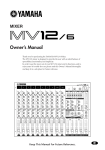
MIXING CONSOLE
Owner's Manual
RTN
L(MONO)
PHANTOM +48V OFF ON
INPUT
INPUT
MIC
INPUT
MIC
INPUT
INPUT
MIC
MIC
INPUT
INPUT
MIC
MIC
INPUT
MIC
ST OUTPUT
SEND
MONI
1
MIC
EFFECT
R
MONI
2
L
R
1
LINE
LINE
LINE
LINE
INS
I⁄O
INS
I⁄O
INS
I⁄O
INS
I⁄O
LINE
LINE
LINE
9
LINE
L(MONO)
11
L(MONO)
3
C-R OUT
2
12 R
10 R
OUT IN
1
2
GAIN
GAIN
+10
-16
-34
-60
3
GAIN
+10
-16
-34
-60
GAIN
+10
-16
PEAK
PEAK
-34
-60
5
GAIN
+10
-16
PEAK
HIGH
HIGH
4
-34
-60
GAIN
+10
-16
PEAK
HIGH
6
-34
-60
GAIN
+10
-16
PEAK
HIGH
7
-34
-60
GAIN
+10
-16
PEAK
HIGH
8
-34
-60
-34
-60
GAIN
-34
+10
HIGH
PHANTOM
-34
+10
L
PEAK
PEAK
PEAK
HIGH
PHONES
GROUP
OUTPUT
INPUT
GAIN
+10
-16
PEAK
HIGH
INPUT
MIXING CONSOLE
4
INSERT I/O
+15
+15
-15
+15
-15
+15
-15
+15
-15
+15
-15
+15
-15
+15
-15
0
+15
-15
RTN
METER
C-R•PHONES
SEND
MONI
+15
-15
10
C-R•PHONES
REC OUT
MONI
-15
POWER
R
L
R
TAPE IN
HIGH
HIGH
MONI 1
TAPE IN
MID
MID
MID
MID
MID
MID
MID
MID
MID
MID
TAPE IN
0
+15
-15
+15
-15
LOW
LOW
+15
-15
LOW
+15
-15
LOW
+15
-15
LOW
+15
-15
LOW
+15
-15
LOW
+15
-15
LOW
+15
-15
+15
-15
10
ST
ST
0
10
0
10
0
10
EFFECT ⁄ MONI 2
ST
ST
EFFECT
⁄ MONI
LOW
LOW
EFFECT
/ MONI 2
MONI 1
0
+15
-15
+15
-15
MONI 1
MONI 1
+15
-15
MONI 1
+15
-15
MONI 1
+15
-15
MONI 1
+15
-15
MONI 1
+15
-15
MONI 1
+15
-15
MONI 1
+15
-15
10
10
0
EFFECT
EFFECT
10
0
EFFECT
10
0
EFFECT
10
0
EFFECT
10
0
EFFECT
10
0
EFFECT
10
0
EFFECT
10
0
10
L
+15
-15
MONI 1
MONI 1
10
0
+5
+3
VOCAL
10
0
L HALL
S HALL
ON
EFFECT
MONI2
EFFECT
EFFECT
R
PEAK
DIGITAL
EFFECT
10
0
0
+1
0
125
0
10
0
10
0
10
0
10
0
10
0
10
0
10
0
10
0
10
0
10
1
2
1
2
1
2
1
2
1
2
1
2
1
2
1
2
1
2
1
2
3
4
3
4
3
4
3
4
3
4
3
4
3
4
3
4
3
4
3
4
500
250
2k
1k
4k
-1
8k
-3
+12
6
PAN
PAN
PAN
PAN
PAN
PAN
-7
6
0
PAN
PAN
-5
+12
-10
0
6
6
-15
-12
-12
-20
BAL
BAL
ST GRAPHIC EQUALIZER
1
3
2
4
1
3
2
4
1
3
2
4
1
3
2
4
1
3
2
4
1
3
2
4
1
3
2
4
1
3
2
4
1
3
2
4
1
3
2
ST
GROUP 3 4
4
10
10
10
10
10
10
10
10
10
10
10
10
10
10
10
5
5
5
5
5
5
5
5
5
5
5
5
5
5
5
0
0
0
0
0
0
0
0
0
0
0
0
0
0
0
5
5
5
5
5
5
5
5
5
5
5
5
5
5
5
10
10
10
10
10
10
10
10
10
10
10
10
10
10
10
15
20
15
20
15
20
15
20
15
20
15
20
15
20
15
20
15
20
15
20
15
20
15
20
15
20
15
20
15
20
30
30
30
30
30
30
30
30
30
30
30
30
30
30
30
40
40
40
40
40
40
40
40
40
40
40
40
40
40
40
00
00
00
00
00
00
00
00
00
00
00
00
00
00
00
1
2
3
4
5
6
7
8
9 10
11 12
GROUP
1
GROUP
2
GROUP
3
GROUP
4
ST
E
Precautions
1. Avoid Excessive Heat, Humidity, Dust and Vibration
Keep the unit away from locations where it is likely to be
exposed to high temperatures or humidity — such as
near radiators, stoves, etc. Also avoid locations which
are subject to excessive dust accumulation or vibration
which could cause mechanical damage.
2. Ventilation
The unit has ventilation slots on the rear and bottom
panels. Do not block these vents.
3. Avoid Physical Shocks
Strong physical shocks to the unit can cause damage.
Handle it with care.
4. Do Not Open the Case or Attempt Repairs or Modifications Yourself
This product contains no user-serviceable parts. Refer
all maintenance to qualified Yamaha service personnel.
Opening the case and/or tampering with the internal
circuitry voids the warranty.
FCC INFORMATION (U.S.A.)
1. IMPORTANT NOTICE: DO NOT MODIFY THIS UNIT! This
product, when installed as indicated in the instructions contained in this
manual, meets FCC requirements. Modifications not expressly
approved by Yamaha may void your authority, granted by the FCC, to
use the product.
2. IMPORTANT: When connecting this product to accessories and/or
another product use only high quality shielded cables. Cable/s supplied
with this product MUST be used. Follow all installation instructions.
Failure to follow instructions could void your FCC authorization to use
this product in the USA.
3. NOTE: This product has been tested and found to comply with the
requirements listed in FCC Regulations, Part 15 for Class “B” digital
devices. Compliance with these requirements provides a reasonable
level of assurance that your use of this product in a residential
environment will not result in harmful interference with other
electronic devices. This equipment generates/uses radio frequencies
and, if not installed and used according to the instructions found in the
users manual, may cause interference harmful to the operation of other
electronic devices. Compliance with FCC regulations does not
guarantee that interference will not occur in all installations. If this
product is found to be the source of interference, which can be
determined by turning the unit “OFF” and “ON”, please try to eliminate
the problem by using one of the following measures: Relocate either
this product or the device that is being affected by the interference.
Utilize power outlets that are on different branch (circuit breaker or
fuse) circuits or install AC line filter/s. In the case of radio or TV
interference, relocate/reorient the antenna. If the antenna lead-in is 300
ohm ribbon lead, change the lead-in to coaxial type cable. If these
corrective measures do not produce satisfactory results, please contact
the local retailer authorized to distribute this type of product. If you can
not locate the appropriate retailer, please contact Yamaha Corporation
of America, Electronic Service Division, 6600 Orangethorpe Ave,
Buena Park, CA 90620
* This applies only to products distributed by YAMAHA
CORPORATION OF AMERICA.
MX12/4—Owner’s Manual
5. Always power off before making connections
Always turn the power OFF before connecting or disconnecting cables. This is important to prevent damage
to the unit itself as well as other connected equipment.
6. Handle Cables Carefully
Always plug and unplug cables — including the AC
power cord — by gripping the connector, not the cord.
7. Clean With a Soft Dry Cloth
Never use solvents such as benzine or thinner to clean
the unit. Wipe clean with a soft, dry cloth.
8. Always Use the Correct Power Supply
Make sure that the power supply voltage specified on the
rear panel matches your local AC mains supply. Also
make sure that the AC mains supply can deliver more
than enough current to handle all equipment used in
your system.
IMPORTANT NOTICE FOR
THE UNITED KINGDOM
Connecting the Plug and Cord
WARNING: THIS APPARATUS MUST BE EARTHED
IMPORTANT: The wires in this mains lead are coloured in accordance with
the following code:
GREEN-AND-YELLOW
BLUE
BROWN
: EARTH
: NEUTRAL
: LIVE
As the colours of the wires in the mains lead of this apparatus may not
correspond with the coloured markings identifying the terminals in your
plug, proceed as follows:
The wire which is coloured GREEN and YELLOW must be connected to
the terminal in the plug which is marked by the letter E or by the safety earth
symbol or coloured GREEN and YELLOW.
The wire which is coloured BLUE must be connected to the terminal which
is marked with the letter N or coloured BLACK.
The wire which is coloured BROWN must be connected to the terminal
which is marked with the letter L or coloured RED.
* This applies only to products distributed by YAMAHA KEMBLE
MUSIC (U.K.) LTD.
MX12/4
1
Thank you for purchasing the Yamaha MX12/4 mixing console. The
MX12/4 is a 12 in/4 group out mixer that provides an ideal balance of
operability, functionality, and simplicity.
In order to take full advantage of the MX12/4's functionality and to enjoy
long and trouble-free use, please read this owner’s manual before use, and
keep it for future reference.
Features
Contents
• The MX12/4 provides 12 input channels, and
mixes them to stereo or to four group outputs.
• A C-R OUT jack is provided for convenient connection to a sub amp for monitoring. You can
monitor the main stereo output, the TAPE IN
input, and the effect/monitor signals.
• A digital effect unit is built-in, allowing you to create a polished mix without the need for additional
equipment.
• Two SEND jacks are provided: the MONO 1 jack
(pre fader) and the EFFECT/MONO 2 jack (post/
pre fader). These can be used as sends for external
effects or a monitor system.
• Phantom power is provided, so that condenser
microphones requiring an external power supply
can be easily connected.
• INS I/O jacks are provided for input channels 1-4,
allowing individual effects to be inserted into each
channel.
• Input channels 1-8 provide both XLR type mic
inputs and TRS phone line inputs. Channels 9-12
provide stereo line inputs. The MX12/4 accommodates a wide range of sources, from microphones to
line level devices and stereo output synthesizers.
• TAPE IN jacks and REC OUT jacks make it easy to
connect tape decks for playback and recording.
Front panel .................................................2
Channel control section .............................. 2
Master control section ................................. 4
Connector section ....................................... 6
Rear panel..................................................8
Application Example...................................9
Specifications ...........................................10
General specifications............................... 10
Input specifications ................................... 11
Output specifications................................. 11
Dimensions ............................................... 12
Block and Level diagram........................... 13
MX12/4—Owner’s Manual
2
Front panel
Front panel
Channel control section
Channels 1~8
(monaural)
Channels 9~12
(stereo)
GAIN
GAIN
1
+10
-16
-34
-60
+10
2
PEAK
HIGH
1 GAIN control
Use this knob to adjust the sensitivity according to the input signal level, so that the input level is appropriate.
For the best balance of S/N ratio and dynamic range, adjust this
knob so that the peak indicator 2 lights occasionally.
-34
~ –16 indicates the MIC input adjustment level, and –34~
+10 indicates the LINE input adjustment level.
+15
This detects the peak level post EQ.
The indicator will light red 3dB before clipping, warning that
clipping level is near.
PEAK
HIGH
–60
2 PEAK indicator
+15
-15
-15
MID
MID
3
+15
-15
+15
-15
LOW
LOW
+15
-15
3 Equalizer
+15
-15
MONI
MONI
4
10
0
10
0
EFFECT
EFFECT
5
0
10
1
2
0
10
1
2
3
4
6
3
This provides ± 15dB of control over the high, mid and low
ranges at the following center frequencies.
HIGH : 12kHz (shelving)
MID : 2.5kHz (peaking)
LOW : 80Hz (shelving)
The frequency response will be flat when the knob is in the “▼”
position.
+20
4
+15
PAN
BAL
1
3
2
4
1
10
3
2
4
Response [dB]
+10
7
+5
0
–5
10
–10
5
5
0
0
5
5
10
10
15
20
15
20
30
8
40
00
–15
–20
MX12/4—Owner’s Manual
100
1k
Frequency [Hz]
10k
20k
4 MONI (monitor) control
This knob controls the level of the signal that is sent from each
channel to the MONI bus.
Since this control is placed before the channel fader, it controls
the level independently from the channel fader setting.
30
40
00
1
20
9 10
5 EFFECT control
This knob controls the level of the signal that is sent from each
channel to the EFFECT bus.
Since this control is placed after the channel fader, the signal
level will be affected by the channel fader setting.
Channel control section
3
6 Group select switches
These switches send the signal of each channel to GROUP buses 1~4.
When the 1 / 2 switches are on (pressed in), the signal will be sent to the GROUP buses 1/2.
When the 3 / 4 switches are on (pressed in), the signal will be sent to the GROUP buses 3/4.
When both switches are on, the signal will be sent to GROUP buses 1/2 and 3/4.
7 PAN (panpot) control
BAL (balance) control
The PAN knobs (channels 1~8) set the stereo position of the signal that is sent to the GROUP
buses 1/2 or 3/4.
The BAL knobs (channels 9~12) set the balance between the left/right channels, and assign
the signals received at inputs 9 L (MONO) and 11 L (MONO) to the GROUP buses 1/3, and
the signals received at inputs 10 R and 12 R to the GROUP buses 2/4.
If signals are input monaurally to input 9 L (MONO) or 11 L (MONO), the same signal will
be sent to groups 1~4.
8 Channel fader
This controls the output level of the input channel signal, adjusting the volume balance
between channels. The faders of unused channels should be lowered.
PEAK
PHANTOM
MASTER
MIC
GROUP
1 2 3 4
INS
I/O
HA
EFFECT
MONI
PHANTOM
EQ
PAN
GAIN
HIGH
PAD
MID
LINE
LOW
INPUT
1-4
EFFECT
PEAK
HA
MIC
MONI
EQ
PAN
GAIN
HIGH
PAD
MID
LINE
LOW
INPUT
5-8
EFFECT
MONI
HA
EQ
L(MONO)
INPUT
9/10
11/12
GAIN
BAL
LOW MID HIGH
PEAK
HA
EQ
R
EFFECT
MONI
MX12/4—Owner’s Manual
4
Front panel
Master control section
1 ST OUT output select switch
5
6 A7
8B
PHANTOM
L
0
ST position ( )
The ST OUTPUT jacks will output the ST bus signal
(the post-fader signals of groups 1~4, the input signals
from the RTN jacks, the return signal from the internal
digital effect, and the input signal from the TAPE IN
jacks).
10
C-R•PHONES
REC OUT
RTN
MONI
0
POWER
R
L
R
TAPE IN
This switch selects the signal which is output via the ST
fader from the ST OUTPUT jacks.
METER
C-R•PHONES
SEND
MONI
MONI 1
TAPE IN
TAPE IN
0
10
ST
ST
0
10
0
10
0
10
EFFECT ⁄ MONI 2
ST
9
ST
EFFECT
⁄ MONI
EFFECT
/ MONI 2
MONI 1
0
0
10
10
0
10
L
R
PEAK
+5
DIGITAL
EFFECT
+3
VOCAL
L HALL
S HALL
ON
EFFECT
MONI2
+1
0
125
500
250
2k
1k
4k
-1
8k
-3
4
+12
+12
6
6
0
0
C
-5
-7
-10
6
6
-15
-12
-12
-20
1
ST GRAPHIC EQUALIZER
ST
GROUP 3 4
10
10
10
10
10
5
5
5
5
5
0
0
0
0
0
5
5
5
5
5
10
10
10
10
10
15
20
15
20
15
20
15
20
15
20
30
30
30
30
30
40
40
40
40
40
00
00
00
00
00
GROUP
1
GROUP
2
GROUP
3
GROUP
4
GROUP 3 4 position ( )
The ST OUTPUT jacks will output the pre-fader signals of groups 3/4.
When this position is selected, the input channel signals will be sent directly to the ST bus without passing
through the group buses 1~4. This setting lets you use
the MX12/4 as a simple 12 in-2 out mixer.
2 ST master fader
This fader adjusts the final combined level of all channels, and sends the signal to the ST OUTPUT jacks.
The meters allow you to view the L and R output levels.
3 GROUP 1~4 faders
2
ST
These faders adjust the signal levels of groups 1~4, and
send their signals to GROUP OUTPUT 1~4 jacks
respectively and to the ST bus.
Groups 1 and 3 are sent to ST L, and groups 2 and 4 are
sent to ST R.
4 Stereo graphic EQ
3
This is a stereo 7-band graphic equalizer that adjust the
tonal quality of the signal output to the ST OUTPUT
jacks.
A ± 12dB boost or cut is provided at each of the frequency bands 125, 250, 500, 1k, 2k, 4k, and 8kHz.
5 TAPE IN jacks
These are line level input jacks to which an external DAT recorder or CD player etc. can be
connected for monitoring. The signals which are input here are sent to the ST bus. The input
levels are adjusted by the TAPE IN ST control (9). Depending on the setting of the C-R•
PHONES select switch (D), the signal can also be monitored directly from the C-R OUT jack.
6 REC OUT jacks
These jacks allow an external DAT recorder or cassette recorder to be connected, to record the
same signal as the ST OUTPUT jacks.
The signals that are output from these jacks are not affected by the settings of the ST master
fader or the graphic EQ. Make recording level adjustments on the recording device.
7 PHANTOM indicator
This indicator will light when the PHANTOM switch (rear panel 2) is on.
8 POWER indicator
This indicator will light when the MX12/4's power is on.
MX12/4—Owner’s Manual
Master control section
5
9 ST control
This knob adjusts the monitor level of the external device (tape deck etc.) connected to the
TAPE IN jacks (5).
0 DIGITAL EFFECT
MONI control—This knob adjusts the level of the return signal which is sent from the internal digital effect to the MONI bus.
ST control—This knob adjusts the level of the return signal which is sent from the internal
digital effect to the ST bus.
Effect select switches—These switches select the effect type for the internal digital effect:
VOCAL, L HALL (large hall), or S HALL (small hall).
Do not attempt to turn off all switches or to simultaneously press two or more switches, since
this will cause malfunctions.
ON switch—This switch turns the internal digital effect on/off. When this is off, no signal will
be sent from the internal digital effect.
A RTN
MONI control—This knob adjusts the level of the signal that is sent from the RTN jacks to the
MONI bus.
ST control—This knob adjusts the level of the signal that is sent from the RTN jacks to the ST
bus. If a signal is input only to the RTN L (MONO) jack, the same signal will be sent to the ST
bus L and R.
B SEND
MONI 1 control—This knob adjusts the level of the MONI bus signal that is output to the
SEND MONI 1 jack.
EFFECT/MONI 2 control—This knob adjusts the level of the EFFECT bus or MONI bus signal that is output to the SEND EFFECT/MONI 2 jack.
The level of the signal that is sent from the EFFECT bus to the internal digital effect is fixed,
and cannot be adjusted (nor by this control).
Output select switch—This switch selects the signal that will be output to the SEND EFFECT/
MONI 2 jack.
EFFECT position (
MONI 2 position (
)—The EFFECT bus signal will be output.
)—The MONI bus signal will be output.
C C-R•PHONES
Here you can select and adjust the signal that is output to the C-R OUT jack and the PHONES
jack.
C-R•PHONES control— This knob adjusts the output level to the C-R OUT jack and
PHONES jack.
Output select switch—These switches select the output signal for the C-R OUT jack and
PHONES jack.
• When the upper switch is on (TAPE IN ), the signal from the TAPE IN
jacks will be output.
• When the upper switch is off ( )
• When the lower switch is off (ST ), the same signal as the ST OUTPUT jacks will be output.
• When the lower switch is on (EFFECT/MONI ), the signal of the
SEND MONI 1 jack will be sent to the L channel, and the SEND
EFFECT/MONI 2 signal will be sent to the R channel.
Meter—The LEDs indicate the output level before the C-R•PHONES control. A position of 0
indicates nominal level, and when clipping level is approached, PEAK will light red as a warning.
MX12/4—Owner’s Manual
6
Front panel
Connector section
1
2
RTN
L(MONO)
PHANTOM +48V OFF ON
INPUT
INPUT
MIC
INPUT
MIC
INPUT
INPUT
MIC
MIC
INPUT
INPUT
MIC
MIC
INPUT
MIC
3
5
ST OUTPUT
SEND
MONI
1
MIC
EFFECT
R
MONI
2
L
R
1
LINE
LINE
LINE
LINE
INS
I⁄O
INS
I⁄O
INS
I⁄O
INS
I⁄O
LINE
LINE
LINE
9
LINE
11
L(MONO)
L(MONO)
3
4
INSERT I/O
OUT IN
1
2
3
C-R OUT
2
12 R
10 R
4
5
6
7
8
INPUT
INPUT
4
PHONES
GROUP
OUTPUT
6
8 7
1 INPUT
MIC (1~8)—These are balanced XLR type mic input jacks (1: ground, 2: hot, 3: cold).
These inputs are compatible with 50~600Ω microphones.
LINE (1~8)—These are balanced TRS phone type line input jacks (T: hot, R: cold, S:
ground).
These inputs are compatible with 600 ohm line level devices.
It is also possible to connect unbalanced phone plugs, but noise may enter the signal if the
cables are long or if the location is susceptible to electromagnetic interference.
Note: It is not possible to connect both the MIC INPUT jack and the LINE INPUT jack for
an individual input channel. Only one or the other jack may be used.
INS I/O 1~4—These are input/output jacks placed between the equalizer and fader of input
channels 1~4.
The nominal input level/impedance is 0dB/600Ω, and the nominal output level/impedance is
0dB/10kΩ.
Devices such as graphic equalizers, compressors or noise filters can be connected here.
The INS I/O jacks provide bi-directional connections using TRS (tip, ring, sleeve) phone
jacks. These connections require a special insertion cable such as shown in the following diagram.
to the input jack of
the external processor
to the INS I/O jack
Sleeve
Tip
Sleeve
Ring
Tip
MX12/4—Owner’s Manual
to the output jack of
the external processor
Connector section
7
2 RTN L (MONO), R
These are unbalanced phone type line input jacks, with a nominal input level and impedance
of +4dB/600Ω.
The signals which are input from these jacks are sent to the ST bus and the MONI bus.
Normally, these jacks are used to receive the return signal from an external effect device such
as reverb or delay, but they can also be used as auxiliary stereo inputs. If only the L (MONO)
jack is connected, the same signal will be sent both to the R jack and L jack, for monaural
input.
3 SEND MONI 1, EFFECT/MONI 2
These are unbalanced phone type output jacks. The nominal input level and impedance are
+4dB/600Ω.
The MONI 1 jack outputs the MONI bus signal, and the EFFECT/MONI 2 jack outputs the
signal of the EFFECT bus or MONI bus. These are used to send signals to an external effect
unit or to a monitor system such as a cue box.
4 INPUT 9~12
These are unbalanced phone type stereo line input jacks, compatible with 600Ω line level
devices.
If only the L (MONO) jack is connected, the same signal will be sent both to the L and R jacks,
for monaural input. In this case, the group select switch (channel control section 6) will send
the same signal to the group buses 1/2 or 3/4.
5 ST OUTPUT (L, R)
These are balanced XLR type output jacks with a nominal output/impedance of +4dB/600Ω.
They provide stereo output of the mixed signal, and are normally connected to a power amp
etc. which drives the main speakers.
These outputs can also be used in order to record the signal at a level adjusted by the ST fader.
6 GROUP OUTPUT 1~4
These are unbalanced phone type output jacks which output the signals of group buses 1~4,
with a nominal output/impedance of +4dB/600Ω. Normally these are connected to the input
jacks of an MTR or an external mixer.
7 C-R OUT
This is a stereo phone type output jack for connection to a monitor system etc., with a nominal output/impedance of +4dB/10kΩ.
The source monitored by this jack is selected by the C-R•PHONES output select switch (master control section C).
Note: An insertion cable can also be used when connecting this jack to a stereo monitor system.
8 PHONES
This is a stereo phone type output jack for connecting a set of headphones.
The source monitored by the headphones is selected by the C-R•PHONES output select
switch (master control section C).
MX12/4—Owner’s Manual
8
Rear panel
Connector polarity
MIC INPUT
ST OUTPUT
Pin 1: ground
Pin 2: hot (+)
Pin 3: cold (–)
LINE Input
Tip: hot (+)
Ring: cold (–)
Sleeve: ground
INS I/O
Tip: Output
Ring: Input
Sleeve: ground
C-R OUT
Tip: L
Ring: R
Sleeve: ground
Stereo Input
RTN
GROUP OUTPUT
SEND MONI1
SEND EFFECT/MONI2
Tip: hot
Sleeve: ground
2
1
1
3
2
3
Ring
Sleeve
Tip
Sleeve
Tip
Rear panel
POWER
ON ⁄ OFF
PHANTOM MASTER
CH1 ~ 8
ON
OFF
(+48V)
1
2
Phantom Power Warning
To prevent hazard or damage, connect
only microphones and cables that
conform to the IEC268-15A standard.
1 POWER switch
When this is on, power is applied to the unit.
When turning off the power, the rule for audio equipment is to turn off devices in the order of
their closeness to the speakers (normally beginning with the power amp).
2 PHANTOM switch
This switch turns the phantom power on/off for all channels 1~8.
Use this when you are using condenser microphones.
When this switch is on, +48V DC will be supplied to pins 2 and 3 of all XLR type MIC INPUT
connectors.
If you do not require phantom power, be sure to set this in the OFF position.
Note: Although it will not cause problems to connect balanced dynamic microphones or line
level devices with this switch turned on, connecting unbalanced devices or devices for which
the center of the transformer is ungrounded may cause hum or malfunction.
MX12/4—Owner’s Manual
Application Example
9
Application Example
Main speakers
Monitors speakers
Power amp
Power amp
Effects processor
88
C-R OUT
INS I/O
ST OUT
Headphone
TAPE IN
PHONES
MIXING CONSOLE
Cassette deck
or DAT
REC OUT
SEND
MTR
Effects processor
88
GROUP
OUTPUT
RTN
INPUT
Mic and line input
MX12/4—Owner’s Manual
10
Specifications
Specifications
■ General specifications
Frequency response
20Hz~20kHz+1dB, –2dB @+4dB
Input Gain control at minimum level
(ST OUT, GROUP OUT, MONITOR OUT, EFFECT OUT@600Ω)
Total harmonic distortion
<0.1%@+14dB 20Hz~20kHz
(ST OUT, GROUP OUT, MONITOR OUT, EFFECT OUT@600Ω)
–128dB equivalent input noise
–95dB residual output noise
(ST OUT, GROUP OUT, MONITOR OUT, EFFECT OUT@600Ω)
Hum and noise
(Rs=150Ω, 20Hz~20kHz)
–87dB (ST OUT/GROUP OUT)
ST master/GROUP fader at nominal level and all
channel fader at minimum.
–64dB (68dB S/N)
(ST OUT/GROUP OUT)
ST master/GROUP fader at nominal level
One channel fader,
Gain control: maximum.
Fader: nominal
–80dB (MONITOR1 OUT, EFFECT/
MONITOR2 OUT)
Master level control at nominal level and all channel
level controls at minimum.
–64dB (68dB S/N)
(MONITOR1 OUT, EFFECT/MONITOR2
OUT)
Master fader at nominal level
One channel fader,
Gain control: maximum.
Fader: nominal
Control level: nominal
Maximum voltage gain
84dB MIC IN to GROUP OUT
58dB LINE IN to GROUP OUT
90dB MIC IN to EFFECT/MONITOR2 OUT
80dB MIC IN to MONITOR1 OUT
Crosstalk at 1kHz
70dB adjacent input
70dB input to output
Gain control
44dB variable
Input channel equalization
±15dB Maximum
HIGH
12kHz shelving
MID LOW
2.5kHz peaking
LOW
80Hz shelving
* Turn over/Roll off frequency of shelving: 3dB below maximum variable level
Meters
12 points LED
Channel peak indicators
An indicator for each channel turns on when the pre-channel fader signal is 3dB below clipping.
Graphic equalizer
7 bands (125, 250, 500, 1k, 2k, 4k, 8kHz)
±12 Maximum
Internal digital effect
3 types
Phantom power
+48V (balanced)
Option
Rack Mount Kit RK124
Power supply/
Power consumption
USA and Canadian
General
Dimensions (WxHxD)
436.2x83.1x401.2mm
Weight
7.0kg
MX12/4—Owner’s Manual
120V AC 60Hz, 30W
230V AC 50Hz, 40W
Input specifications
11
■ Input specifications
Input level
Input
connectors
Gain
trim
Input
impedance
Nominal
impedance
MIC INPUT
(1-8)
MAX
MIN
5kΩ
LINE INPUT
(1-8)
MAX
MIN
ST INPUT
(9-12)
MAX
MIN
Connector type
Sensitivity1
Nominal level
Max. before
clipping
50~600Ω mic
–90dB (24.5µV)
–36dB (12.3mV)
–60dB (775µV)
–16dB (123mV)
–40dB (7.75mV)
+4dB (1.23V)
XLR3-31 type2
50kΩ
600Ω line
–64dB (490µV)
–10dB (245mV)
–34dB (15.5mV)
+10dB (2.45V)
–14dB (155mV)
+30dB (24.5V)
Phone jack (TRS)
10kΩ
600Ω line
–54dB (1.55mV)
–10dB (245mV)
–34dB (15.5mV)
+10dB (2.45V)
–14dB (155mV)
+30dB (24.5V)
Phone jack3
RTN (L•R)
10kΩ
600Ω line
–12dB (195mV)
+4dB (1.23V)
+20dB (7.75V)
Phone jack3
TAPE IN (L•R)
10kΩ
600Ω line
–26dBV (50.1mV)
–10dBV (316mV)
+18dBV (7.75V)
RCA pin jack
INS I/O (1-4)
10kΩ
600Ω line
–20dB (77.5mV)
0dB (775mV)
+20dB (7.75V)
1.
2.
3.
4.
•
2
Phone jack (I/O)4
Sensitivity is the lowest level that will produce an output of +4 dB (1.23V) or the nominal output level when the unit is set to maximum gain.
XLR type connectors and phone jacks (TRS) (T=Hot, R=Cold, S=Gnd) are balanced.
Phone jacks are unbalanced.
Phone jacks (I/O) (T=OUT, R=IN, S=GND) are unbalanced.
0dB=0.775Vrms, 0dBV=1Vrms
■ Output specifications
Output connector
Output
impedance
Nominal
impedance
Output level
Connector type
Nominal
Max. before clipping
ST OUTPUT
(L•R)
150Ω
600Ω Lines
+4dB (1.23V)
+24dB (12.3V)
XLR-3-32 type1
GROUP OUTPUT
(1-4)
75Ω
600Ω Lines
+4dB (1.23V)
+20dB (7.75V)
Phone jack2
MONITOR1 OUT
75Ω
600Ω Lines
+4dB (1.23V)
+20dB (7.75V)
Phone jack2
SEND MONI1,
EFFECT/MONI2
75Ω
600Ω Lines
+4dB (1.23V)
+20dB (7.75V)
Phone jack2
C-R OUT
470Ω
10kΩ Lines
+4dB (1.23V)
+20dB (7.75V)
ST phone jack3
600Ω
10kΩ Lines
–10dBV (316mV)
+10dBV (3.16V)
100Ω
40Ω Phones
3mW
100mW
600Ω
10kΩ Lines
0dB (775mV)
+20dB (7.75V)
REC OUT
(L•R)
PHONES
INS I/O
1.
2.
3.
4.
•
(1-4)
RCA pin jack
ST phone jack
Phone jack4
XLR type connectors are balanced.
Phone jacks are unbalanced.
ST phone jacks (T=L, R=R, S=GND) are unbalanced.
Phone jacks (I/O) (T=OUT, R=IN, S-GND) are unbalansed.
0dB=0.775Vrms, 0dBV=1Vrms
MX12/4—Owner’s Manual
12
Specifications
■ Dimensions
310
H:83.1
3.2
W:436.2
Specifications are subject to change without prior notice.
MX12/4—Owner’s Manual
D:401.2
320
13.5
76.6
Units:mm
13
Block and Level diagram
■ Block and Level diagram
PEAK
GROUP
1 2 3 4
INS
I/O
PHANTOM
MASTER
ST
L R
EFFECT
MONI
PHANTOM
1
GROUP 1
HA
MIC
EQ
PAN
INPUT
1-4
MID
LOW
GAIN
HIGH
2
PAD
LINE
GROUP 2
EFFECT
GROUP
OUTPUT
MONI
PEAK
3
GROUP 3
MIC
HA
EQ
INPUT
5-8
PAN
4
GROUP 4
HIGH
GAIN
MID
LOW
PAD
LINE
EFFECT
L
MONI
HA
PAD
REC OUT
EQ
R
L(MONO)
PEAK
INPUT
9/10
11/12
GAIN
BAL
LOW MID HIGH
HA
L
7 BAND ST GEQ
ST
EQ
125 250
4k
ST
OUTPUT
8k
R
ST
EFFECT
7 BAND ST GEQ
R
GROUP 3 4
MONI
MONI 1
MONI 1
EFFECT
SEND
L(MONO)
MONI 2
ST
RTN
(to DSP)
EFFECT/
MONI 2
EFFECT/
MONI 2
R
ST
PAD
MONI
EFFECT
/MONI
(from EFFECT)
DSP
ON
VOCAL
L HALL
S HALL
ST
MONI
C-R OUT
L
C-R.PHONES
TAPE IN
ST
R
TAPE IN
PHONES
20
10
20
LINE
ST
EFFECT,MONITOR
RTN
0
TAPE
–10
–20
–30
0
–10
–20
LINE
–40
ST
–30
–40
–50
–60
ST
REC
EFFECT,MONITOR,TAPE
GROUP,ST
MIC
10
GROUP,EFFECT,MONITOR
EFFECT
INS
–50
MIC
–60
MX12/4—Owner’s Manual
VV68420 R0 1 IP
96 09 700 NP Printed in Taiwan
YAMAHA CORPORATION
P.O.Box 1, Hamamatsu, Japan