1
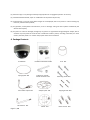
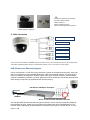
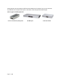
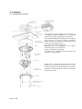
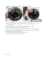
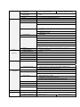
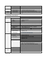
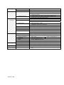
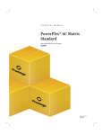
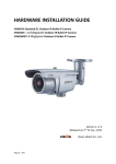
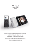
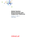
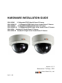
HARDWARE INSTALLATION GUIDE VDA110SMi 1.3 Megapixel(720P) Vandal Dome IP Camera VDA110SMi‐IR 1.3 Megapixel(720P) Night Vision Vandal Dome IP Camera VDA110SM3i 3.0 Megapixel(1080P) Vandal Dome IP Camera VDA110SM3i‐IR 3.0 Megapixel(1080P) Night Vision Vandal Dome IP Camera VDA110EHi Standard D1 Vandal Dome IP Camera VDA110EHi‐IR Standard D1 Night Vision Vandal Dome IP Camera Version 1. 0. 2 Released on 1 of Sept., 2011 Vision Hitech Co., Ltd. st
Page 1 / 16
PRECAUTIONS By selecting this product, you have decided to use a professional device that guarantees highest quality and reliability. We would like to thank you very much for your confidence and kindly ask you to read the following instructions carefully before installation and operation in order to take full advantage of all quality features regarding this product. The lighting flash with an arrowhead symbol, within an equilateral triangle is intended to alert the user to the presence of non‐insulated dangerous voltage within the product’s enclosure that may be of sufficient magnitude to constitute a risk of electric shock to persons. The exclamation point within an equilateral triangle is intended to alert the user to the presence of important operating and maintenance (servicing) instructions in the literature accompanying the appliance. INFORMATION This equipment has been tested and found to comply with limits for a Class A digital device, pursuant to part 15 of the FCC Rules. These limits are designed to provide reasonable protection against harmful interference when the equipment is operated in a commercial environment. This equipment generates, uses, and can radiate radio frequency energy and, if not installed and used in accordance with the instruction manual, may cause harmful interference to radio communications. Operation of this equipment in a residential area is likely to cause harmful interference in which case the user will be required to correct the interference at its own expense. WARNING Changes or modifications not expressly approved by the manufacturer could void the user’s authority to operate the equipment. CAUTION – To prevent electric shock and risk of the fire hazards ‐Do NOT use power source other than that specified. ‐Do NOT expose this appliance to rain or moisture. Trademarks All names used in this manual for hardware and software are probably registered trademarks of respective companies. This installation should be made by a qualified service person and should conform to all local codes. Page 2 / 16
Table of content Hardware Installation Guide 1. Precautions ‐‐‐‐‐‐‐‐‐‐‐‐‐‐‐‐‐‐‐‐‐‐‐‐‐‐‐‐‐‐‐‐‐‐‐‐‐‐‐‐‐‐‐‐‐‐‐‐‐‐‐‐‐‐‐‐‐‐‐‐‐‐‐‐‐‐‐‐‐‐‐‐‐‐‐‐‐‐‐‐‐‐‐‐‐‐‐‐‐‐‐‐‐‐‐‐‐‐‐‐ 4 2. Limitation of liability ‐‐‐‐‐‐‐‐‐‐‐‐‐‐‐‐‐‐‐‐‐‐‐‐‐‐‐‐‐‐‐‐‐‐‐‐‐‐‐‐‐‐‐‐‐‐‐‐‐‐‐‐‐‐‐‐‐‐‐‐‐‐‐‐‐‐‐‐‐‐‐‐‐‐‐‐‐‐‐‐‐‐‐‐‐‐‐‐ 4 3. Disclaimer of warranty ‐‐‐‐‐‐‐‐‐‐‐‐‐‐‐‐‐‐‐‐‐‐‐‐‐‐‐‐‐‐‐‐‐‐‐‐‐‐‐‐‐‐‐‐‐‐‐‐‐‐‐‐‐‐‐‐‐‐‐‐‐‐‐‐‐‐‐‐‐‐‐‐‐‐‐‐‐‐‐‐‐‐‐‐‐ 4 4. Package Contents ‐‐‐‐‐‐‐‐‐‐‐‐‐‐‐‐‐‐‐‐‐‐‐‐‐‐‐‐‐‐‐‐‐‐‐‐‐‐‐‐‐‐‐‐‐‐‐‐‐‐‐‐‐‐‐‐‐‐‐‐‐‐‐‐‐‐‐‐‐‐‐‐‐‐‐‐‐‐‐‐‐‐‐‐‐‐‐‐‐‐‐‐‐ 5 5. Cable Connection ‐‐‐‐‐‐‐‐‐‐‐‐‐‐‐‐‐‐‐‐‐‐‐‐‐‐‐‐‐‐‐‐‐‐‐‐‐‐‐‐‐‐‐‐‐‐‐‐‐‐‐‐‐‐‐‐‐‐‐‐‐‐‐‐‐‐‐‐‐‐‐‐‐‐‐‐‐‐‐‐‐‐‐‐‐‐‐‐‐‐‐‐‐ 6 6. Installation ‐‐‐‐‐‐‐‐‐‐‐‐‐‐‐‐‐‐‐‐‐‐‐‐‐‐‐‐‐‐‐‐‐‐‐‐‐‐‐‐‐‐‐‐‐‐‐‐‐‐‐‐‐‐‐‐‐‐‐‐‐‐‐‐‐‐‐‐‐‐‐‐‐‐‐‐‐‐‐‐‐‐‐‐‐‐‐‐‐‐‐‐‐‐ 8 7. Dimension (mm) ‐‐‐‐‐‐‐‐‐‐‐‐‐‐‐‐‐‐‐‐‐‐‐‐‐‐‐‐‐‐‐‐‐‐‐‐‐‐‐‐‐‐‐‐‐‐‐‐‐‐‐‐‐‐‐‐‐‐‐‐‐‐‐‐‐‐‐‐‐‐‐‐‐‐‐‐‐‐‐‐‐‐‐‐‐‐‐‐‐‐‐‐‐‐‐ 12 8. Specification ‐‐‐‐‐‐‐‐‐‐‐‐‐‐‐‐‐‐‐‐‐‐‐‐‐‐‐‐‐‐‐‐‐‐‐‐‐‐‐‐‐‐‐‐‐‐‐‐‐‐‐‐‐‐‐‐‐‐‐‐‐‐‐‐‐‐‐‐‐‐‐‐‐‐‐‐‐‐‐‐‐‐‐‐‐‐‐‐‐‐‐‐‐‐‐‐‐‐‐‐‐ 12 VDA110SMi / VDA110SMi‐IR ‐‐‐‐‐‐‐‐‐‐‐‐‐‐‐‐‐‐‐‐‐‐‐‐‐‐‐‐‐‐‐‐‐‐‐‐‐‐‐‐‐‐‐‐‐‐‐‐‐‐‐‐‐‐‐‐‐‐‐‐‐‐‐‐‐‐‐‐‐‐‐‐‐‐‐‐‐‐‐‐‐‐‐‐‐‐‐‐‐ 12 VDA110SM3i / VDA110SM3i‐IR ‐‐‐‐‐‐‐‐‐‐‐‐‐‐‐‐‐‐‐‐‐‐‐‐‐‐‐‐‐‐‐‐‐‐‐‐‐‐‐‐‐‐‐‐‐‐‐‐‐‐‐‐‐‐‐‐‐‐‐‐‐‐‐‐‐‐‐‐‐‐‐‐‐‐‐‐‐‐‐‐‐‐‐‐‐‐ 13 VDA110EHi / VDA110EHi‐IR ‐‐‐‐‐‐‐‐‐‐‐‐‐‐‐‐‐‐‐‐‐‐‐‐‐‐‐‐‐‐‐‐‐‐‐‐‐‐‐‐‐‐‐‐‐‐‐‐‐‐‐‐‐‐‐‐‐‐‐‐‐‐‐‐‐‐‐‐‐‐‐‐‐‐‐‐‐‐‐‐‐‐‐‐‐‐‐‐‐‐‐‐ 15 Page 3 / 16
1. Precautions z Please read the manual carefully before the installation in order to set up the camera correctly and to obtain the best picture quality. z
Please keep the manual in good condition for your future reference and service application. Installation and services should be only carried out by an authorized personnel according to local safety regulations. z
z
If any liquid or solid matter gets into the housing, immediately disconnect the camera from power supply and have it checked by your authorized dealer before reusing. z
z
Avoid installing the camera at extremely hot or cold places. If you are not a certified person, never try to dismantle the camera. To avoid electric shock, never remove the screws or covers. There are no parts inside that need maintenance by the user. All maintenance should be carried out by qualified personnel. z
z
z
Avoid installing the camera at a place of high humidity. Avoid installing the camera at the place exposed to gas or oil. Keep the top glass of the lens always clean in order to obtain the best picture quality all the time. Be careful not to be stained by fingerprint. Don't face the camera directly toward sunlight or sunlight reflecting area. CCD may go defective at this condition. Please give a special attention to keep the unit from dangerous drop or external shock during the process of transportation or handling. z
z
z
z
Never try to touch the camera in wet hand. It may cause an electric shock. Do not expose the camera to radioactivity. It causes a serious damage on the CCD. 2. Limitation of liability This publication is provided “AS IS” without warranty of any kind, either express or implied, including but not limited to, the implied warranties of merchantability, fitness for any particular purpose, or non‐infringement of the third party's right. This publication could include technical inaccuracies or typographical errors. Changes are added to the information herein, at any time, for the improvements of this publication and/or the corresponding product(s). 3. Disclaimer of warranty In no event shall seller be liable to any party or any person, except for replacement or reasonable maintenance of the product, for the cases, including but not limited to below: (1) Any damage and loss, including without limitation, direct or indirect, special, consequential or exemplary, arising out of or relating to the product; Page 4 / 16
(2) Personal injury or any damage caused by inappropriate use or negligent operation of the user; (3) Unauthorized disassemble, repair or modification of the product by the user; (4) Inconvenience or any loss arising when images are not displayed, due to any reason or cause including any failure or problem of the product; (5) Any problem, consequential inconvenience, or loss or damage, arising out of the system combined by the devices of third party. (6) Any claim or action for damages, brought by any person or organization being photogenic subject, due to violation of privacy with the result of that surveillance‐camera's picture, including saved data, for some reason, becomes public or is used for the purpose other than surveillance. 4. Package Contents IP Camera Hardware Installation Guide
Fuse 1EA Sponge plate 1EA L‐Wrench 1.5mm &
Socket Set Screw 1EA Extra Video output 1EA Adaptor plate 1EA
Star Wrench 1EA Sticker 1EA
Page 5 / 16
Mounting screws 4EA Tapping Screws 4EA Plastic anchor 4EA CD
‐
‐
‐
‐
‐
Hardware Installation Guide (PDF) IP Camera Manual (PDF) NVR Pro Manual NVR Lite (16Ch) Program IPScan Utility Program (IP Installer) Power Adaptor (Option) 5. Cable Connection Power Connector (DC12V)
Network Connector
Analog Video Out
Sensor In
Audio-in (Option)
Audio-out (Option)
This IP camera uses 12VDC or IEEE802.3af PoE for power source. Please make sure to use a UL/CE approved and 12VDC regulated power supply or standard PoE injector, mid‐ or end‐span for input power. PoE (Power over Ethernet) Support
Power over Ethernet, or PoE, technology describes a system to transmit electrical power, along with
data, to remote devices over standard twisted-pair cable in an Ethernet network. This technology is
useful for powering IP telephones, wireless LAN access points, network cameras, remote network
switches, embedded computers, and other appliances where it would be inconvenient and expensive.
(Main wiring must be done by qualified and/or licensed person)
PoE Switch / Mid-Span / End-Span
AC Power
Ethernet
Direct connection with standard LAN cable
The standard IEEE 802.3af describes two types of devices: Power Sourcing Equipment (PSE)and
Powered Devices (PD). Power sourcing equipment provides power to the powered devices. The
network camera represents the powered device, whereas a PoE Injector is a PSE device. The Pro
Page 6 / 16
Series Network Camera models are IEEE 802.3af standard PoE compliant. They can be used with
any IEEE 802.3af-compliant PoE injector, PoE switch, PoE mid-span and PoE end-span.
Various types of PoE equipments
Power over Ethernet (PoE) Injector
Page 7 / 16
PoE Mid-span
PoE Office Switch
6. Installation 6.1. Installation overview The ceiling tile should be applied for only when there is an additional support available for it to hold the camera with enough strength after the installation. Take it off after drilling the mounting hole on the guide.
Pease make sure to attach the Moisture protection sponge securely on the back of the base. Warranty is void if it is not attached properly. Pre installation of the base is possible. Mounting holes are compatible to the industry standard 2‐gang electric junction box. Screws are supplied in the package. The camera set is separated from the base with the supplied 2 mounting screws. Dome cover is externally revolved with hand for multiple uses. Press the dome and turn it to a clear part with hand when the existing part of the window is scratched or contaminated. No need to disassemble the dome for this job. Page 8 / 16
6.2. How to reposition the cable from the back to the side of base. (D)
(A)
(B)
(C)
Pull off these two connectors
<Figure 1> <Figure 2> ① Figure 1 shows factory default set up. The cable comes out to the side of base. ② Unscrew the two screws of (A) and (B) and disassemble the small PCB board (C) from the main board. (See Figure 2) ③ Unscrew the cable tie and the wire (Hanger) as in the figure above. ((D) in Figure 2) ④ Pull off the two connectors and let them out through the side hole. ⑤ Take off the Conduit cap on the bottom of the base with a coin and fix it on the side conduit hole. ⑥ Put the cable into the base through the bottom conduit hole and connect those two connectors to the same location from which they were taken off. ⑦ Fix the cable and the safety wire (Hanger) with cable tie and screw. ⑧ Assemble the small upper PCB board again as before. Page 9 / 16
6.3. How to adjust the Zoom/Focus. 6.3.1. Parts location Page 10 / 16
6.3.2. Zoom/Focus adjustment Zoom and Focus locking levers are tightened and positioned at top side so that they can be accessed by hand at factory. 1. Please loosen the zoom/focus levers a little bit by turning them counter‐clockwise with finger. 2. Move the lever left or right to adjust the zoom and focus. 3. Please lock them tightly after the adjustment by turning them clockwise with finger. 6.4. How to adjust the camera angle. 6.4.1. Panning 180° ∙ Angle adjustment either to the left direction or right direction within 180° is possible. 1. Hold the Pan locking ring with hand and loosen it by turning it counterclockwise as in the picture left. 2. Adjust the panning angle and lock the Pan locking ring by turning it clockwise as in the picture. 6.4.2. Tilt 90° ∙ Angle adjustment of up to maximum 90° downward is possible. 1. Hold the Tilt locking levers on both sides with hand and loosen it by turning it counter‐clockwise as in the picture left. 2. Adjust the Tilt angle with hand and lock the Tilt locking lever by turning it clockwise as in the picture. 6.4.3. Rotation 360° ‐ Grab the both ends of the Rotation handle as in the picture and adjust the angle to the direction you want. ‐ Angle adjustment either to the left direction or right direction within 360° is possible. Page 11 / 16
7. Dimension (mm) 8. Specification 8.1. VDA110SMi / VDA110SMi‐IR Classification
General
Image
Pickup
Video
CPU
Specification
VDA110SMi
VDA110SMi-IR
32-bit ARM9 RISC CPU up to 533MHz, 32KB I/D-Cache, MMU
Video Buffer
16Mbyte Video Frame Buffer
Flash
16 Mbyte Flash Memory
SDRAM
256Mbyte
Image sensor
1.3 Megapixel 1/3" SONY progressive scan CMOS image sensor
Total Pixels
1384(H) x 1076(V) 1.49 Megapixel
Effective Pixels
1329(H) x 1049(V) 1.39 Megapixel
S/N Ratio
Min. Illumination &
IR Distance
More than 50dB
0.5 Lux with DSSX2
(F1.2, 30IRE, AGC On)
Day & Night
ICR
Lens Control
Lens
Video compression
Resolutions
DC Iris
3.5~16mm Vari-focal Megapixel Lens
H.264 baseline profile, Motion JPEG
Up to 1280 x 720
Frame rate
H.264 Up to 30fps with 1280x720
0Lux (IR On)
30M (21 Built-in IR LED’s)
MJPEG up to 15 fps with VGA (Simultaneous stream with H.264)
Video streaming
MJPEG Up to 30fps with 720P resolution (Single MJPEG stream)
Support multi stream with H.264, MJPEG
Adjustable frame rate
VBR/CBR in H.264
Pan/Tilt/Zoom
Image setting
Digital PTZ
Day & Night
Auto White Balance
Auto Exposure
Privacy Mask
Effect - Color, Sharpness, Mirror/V-Flip, etc.
Page 12 / 16
Audio
(Option)
Network
Output
BNC x1, 1.0Vp-p, 75 ohm Composite Video, NTSC/PAL
Audio streaming
Two-way, full duplex
Audio compression
G.711
Sample Rate
8KHZ
Data Rate
64Kbps
Audio input
Microphone input /1 x Line-In (Mono)
Audio output
Line output/ 1 x Line-Out (Mono)
Security
Password protection
User access log
HTTPS encryption
System
integration
Supported protocol
HTTP, HTTPS, FTP, SMTP, UPnP, DNS, DynDNS, NTP
Intelligent video
RTSP, RTP, TCP, UDP, ICMP, DHCP
Motion detection up to 1280x720 with 32x24 blocks
Alarm trigger
Motion detection
Alarm events
File upload via ftp, e-mail
External input/Normal Open/Close Type
Notification via email, FTP and TCP
External output activation/Normal Open/Close Type
Video buffer
16MB pre-alarm and post-alarm
Recording
Save to Micro-SD card with event mode and continuous mode
Firmware upgrade
Remote upgrade via network
API
CGI Interface document
ActiveX Interface(ocx(dll) + document)
etc
RESET Button
1 x Factory Reset Button
Physical
Power Source
DC 12V/1.5A, PoE(Power over Ethernet): 802.3af
Power Consumption
Max. 5.5W
Net Weight
2000g Appr.(Camera Only)
LED's
Power, Network Connection
Dimension
164(Ø) x121.5(H)
Operating Temperature
-25 degree~50 degree Celsius(-13F~122F)
Environment
Max. 7.2W with IR On
Storage Temperature
-25 degree~60 degree Celsius(-13F~140F)
Software
Included Software
NVR Lite (16 Channel), IP Installer (Windows only)
Package
Package Contents
Network Camera, Use Manual, External Power Adaptor, Software
CD
8.2. VDA110SM3i / VDA110SM3i‐IR Classification
General
Image
Pickup
Page 13 / 16
CPU
Specification
VDA110SM3i
VDA110SM3i-IR
32-bit ARM9 RISC CPU up to 533MHz, 32KB I/D-Cache, MMU
Video Buffer
16Mbyte Video Frame Buffer
Flash
16 Mbyte Flash Memory
SDRAM
256Mbyte
Image sensor
3.0 Megapixel 1/2.8" SONY progressive scan CMOS image sensor
Total Pixels
2144(H) x 1588(V) 3.4 Megapixel
Effective Pixels
2144(H) x 1561(V) 3.27 Megapixel
S/N Ratio
More than 52dB
Video
Min. Illumination &
IR Distance
1 Lux with DSSX2
(F1.2, 30IRE, AGC On)
0Lux (IR On)
30M (21 Built-in IR LED’s)
Day & Night
ICR
Lens Control
Lens
Video compression
Resolutions
DC Iris
3.5~16mm Vari-focal Megapixel Lens
H.264 baseline profile, Motion JPEG
Up to 1920 x 1080
Frame rate
H.264 Up to 15fps with 1920x1080
MJPEG up to 15 fps with VGA (Simultaneous stream with H.264)
Video streaming
MJPEG Up to 30fps with 720P resolution (Single MJPEG stream)
Support multi stream with H.264, MJPEG
Adjustable frame rate
VBR/CBR in H.264
Pan/Tilt/Zoom
Digital PTZ
Image setting
Day & Night
ATR (WDR)
Auto White Balance
Auto Exposure
Privacy Mask
Effect - Color, Sharpness, Mirror/V-Flip, etc.
Audio
(Option)
Network
Output
BNC x1, 1.0Vp-p, 75 ohm Composite Video, NTSC/PAL
Audio streaming
Two-way, full duplex
Audio compression
G.711
Sample Rate
8KHZ
Data Rate
64Kbps
Audio input
Microphone input /1 x Line-In (Mono)
Audio output
Line output/ 1 x Line-Out (Mono)
Security
Password protection
User access log
HTTPS encryption
System
integration
Supported protocol
HTTP, HTTPS, FTP, SMTP, UPnP, DNS, DynDNS, NTP
Intelligent video
RTSP, RTP, TCP, UDP, ICMP, DHCP
Motion detection up to 1920x1080 with 32x24 blocks
Alarm trigger
Motion detection
External input/Normal Open/Close Type
Alarm events
File upload via ftp, e-mail
Notification via email, FTP and TCP
External output activation/Normal Open/Close Type
Video buffer
16MB pre-alarm and post-alarm
Recording
Save to Micro-SD card with event mode and continuous mode
Firmware upgrade
Remote upgrade via network
API
CGI Interface document
ActiveX Interface(ocx(dll) + document)
etc
RESET Button
1 x Factory Reset Button
Physical
Power Source
DC 12V/1.5A, PoE(Power over Ethernet): 802.3af
Power Consumption
Max. 5.5W
Page 14 / 16
Max. 7.2W with IR On
Environment
Net Weight
2000g Appr.(Camera Only)
LED's
Power, Network Connection
Dimension
164(Ø) x121.5(H)
Operating Temperature
-25 degree~50 degree Celsius(-13F~122F)
Storage Temperature
-25 degree~60 degree Celsius(-13F~140F)
Software
Included Software
NVR Lite (16 Channel), IP Installer (Windows only)
Package
Package Contents
Network Camera, Use Manual, External Power Adaptor, Software
CD
8.3. VDA110EHi / VDA110EHi‐IR Classification
General
Image
Pickup
CPU
Specification
VDA110EHi
VDA110EHi-IR
32-bit ARM9 RISC CPU up to 533MHz, 32KB I/D-Cache, MMU
Video Buffer
16Mbyte Video Frame Buffer
Flash
16 Mbyte Flash Memory
SDRAM
256Mbyte
Image sensor
1/3" Sony 960H Ex-view HAD CCDⅡ
Effective Pixels
NTSC : 976(H) x 494(V), PAL : 976(H) x 582(V)
H. Resolution
Synchronizing system
650TV Lines(Color)/ 700TV Lines(B/W)
Scanning system
S/N Ratio
Min. Illumination
Video
Internal
NTSC : 525 Lines PAL : 625 Lines 2:1 Interlaced
More than 52dB (AGC Off)
0.1 Lux (Color), 0.01Lux (B/W)
0Lux (IR On)
Shutter Speed
NTSC:1/60~1/100,000 sec. PAL:1/50~1/100,000 sec.
Gamma Correction
Standard γ = 0.45
Lens (Standard)
2.8-12mm Vari-focal DC Auto Iris lens
Video compression
Resolutions
Frame rate
H.264 baseline profile, Motion JPEG
Up to D1(NTSC:720X480, PAL:720X576)
H.264 Up to 30fps at D1
MJPEG Up to 30fps at D1
Support multi stream with H.264, MJPEG
Adjustable frame rate
VBR/CBR in H.264
Digital PTZ
Day & Night
ATR (WDR)
Auto White Balance
Auto Exposure
Video streaming
Pan/Tilt/Zoom
Image setting
Effect - Color, Sharpness, Mirror/V-Flip, etc.
BNC x1, 1.0Vp-p, 75 ohm Composite Video, NTSC/PAL
Privacy Mask
Effect - Color, Sharpness, Mirror/V-Flip, etc.
Audio
(Option)
Page 15 / 16
Output
BNC x1, 1.0Vp-p, 75 ohm Composite Video, NTSC/PAL
Audio streaming
Two-way, full duplex
Audio compression
G.711
Sample Rate
8KHZ
Data Rate
64Kbps
Network
Audio input
Microphone input /1 x Line-In (Mono)
Audio output
Line output/ 1 x Line-Out (Mono)
Security
Password protection
User access log
HTTPS encryption
System
integration
Supported protocol
HTTP, HTTPS, FTP, SMTP, UPnP, DNS, DynDNS, NTP
Intelligent video
RTSP, RTP, TCP, UDP, ICMP, DHCP
Motion detection up to 1280x720 with 32x24 blocks
Alarm trigger
Motion detection
External input/Normal Open/Close Type
Alarm events
File upload via ftp, e-mail
Video buffer
16MB pre-alarm and post-alarm
Recording
Save to Micro SD card with event mode and continuous mode
Notification via email, FTP and TCP
Firmware upgrade
Remote upgrade via network
API
CGI Interface document
ActiveX Interface(ocx(dll) + document)
Physical
Environment
RESET Button
1 x Factory Reset Button
Power Source
DC 12V/1.5A, PoE(Power over Ethernet): 802.3af
Power Consumption
Max. 5.5W
Net Weight
520g Appr.(Camera Only)
LED's
Power, Network Connection
Dimension
134(Ø) x91.7(H)
Max. 7.2W with IR On
Operating Temperature
-25 degree~50 degree Celsius (-13F~122F)
Storage Temperature
-25 degree~60 degree Celsius (-13F~140F)
Software
Included Software
NVR Lite (16 Channel), IP Installer (Windows Only)
Package
Package Contents
Network Camera, Use Manual, External Power Adaptor, Software
CD
■ SpecificaƟons are subject to change without prior noƟce to enhance performance and stability
Page 16 / 16