1
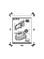
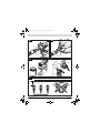
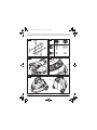
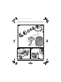
OBJ_BUCH-1543-001.book Page 1 Friday, November 18, 2011 9:16 AM
Robert Bosch GmbH
Power Tools Division
70745 Leinfelden-Echterdingen
Germany
PFS 105 E WALLPaint
www.bosch-pt.com
1 619 929 K18 (2011.11) PS / 186 UNI
de
en
fr
es
pt
it
nl
Originalbetriebsanleitung
Original instructions
Notice originale
Manual original
Manual original
Istruzioni originali
Oorspronkelijke
gebruiksaanwijzing
da Original brugsanvisning
sv Bruksanvisning i original
no Original driftsinstruks
fi Alkuperäiset ohjeet
el
tr
pl
cs
sk
hu
ru
Ðñùôüôõðï ïäçãéþí ÷ñÞóçò
Orijinal işletme talimat
Instrukcja oryginalna
Původní návod k používání
Pôvodný návod na použitie
Eredeti használati utasítás
Îðèãèíàëüíîå ðóêîâîäñòâî ïî
ýêñïëóàòàöèè
uk Îðèã³íàëüíà ³íñòðóêö³ÿ ç
åêñïëóàòàö³¿
ro Instrucţiuni originale
bg Îðèãèíàëíà èíñòðóêöèÿ
sr
sl
hr
et
lv
lt
Originalno uputstvo za rad
Izvirna navodila
Originalne upute za rad
Algupärane kasutusjuhend
Instrukcijas oriģinālvalodā
Originali instrukcija
OBJ_BUCH-1543-001.book Page 2 Friday, November 18, 2011 9:16 AM
2|
Deutsch . . . . . . . . . . . . . . . . . . . . . . . . . . . . . . . . . . . . . . . . . Seite
7
English . . . . . . . . . . . . . . . . . . . . . . . . . . . . . . . . . . . . . . . . . . Page
13
Français . . . . . . . . . . . . . . . . . . . . . . . . . . . . . . . . . . . . . . . . . Page
20
Español . . . . . . . . . . . . . . . . . . . . . . . . . . . . . . . . . . . . . . . .Página
27
Português. . . . . . . . . . . . . . . . . . . . . . . . . . . . . . . . . . . . . . .Página
34
Italiano . . . . . . . . . . . . . . . . . . . . . . . . . . . . . . . . . . . . . . . . .Pagina
41
Nederlands . . . . . . . . . . . . . . . . . . . . . . . . . . . . . . . . . . . . .Pagina
48
Dansk . . . . . . . . . . . . . . . . . . . . . . . . . . . . . . . . . . . . . . . . . . . Side
55
Svenska . . . . . . . . . . . . . . . . . . . . . . . . . . . . . . . . . . . . . . . . . Sida
61
Norsk . . . . . . . . . . . . . . . . . . . . . . . . . . . . . . . . . . . . . . . . . . . Side
66
Suomi. . . . . . . . . . . . . . . . . . . . . . . . . . . . . . . . . . . . . . . . . . . .Sivu
73
ÅëëçíéêÜ. . . . . . . . . . . . . . . . . . . . . . . . . . . . . . . . . . . . . . . . Óåëßäá
78
Türkçe . . . . . . . . . . . . . . . . . . . . . . . . . . . . . . . . . . . . . . . . . Sayfa
85
Polski . . . . . . . . . . . . . . . . . . . . . . . . . . . . . . . . . . . . . . . . . .Strona
92
Česky . . . . . . . . . . . . . . . . . . . . . . . . . . . . . . . . . . . . . . . . . . Strana
98
Slovensky. . . . . . . . . . . . . . . . . . . . . . . . . . . . . . . . . . . . . . . Strana 105
Magyar . . . . . . . . . . . . . . . . . . . . . . . . . . . . . . . . . . . . . . . . . . Oldal 111
Ðóññêèé . . . . . . . . . . . . . . . . . . . . . . . . . . . . . . . . . . . . . Ñòðàíèöà 118
Óêðà¿íñüêà. . . . . . . . . . . . . . . . . . . . . . . . . . . . . . . . . . . .Ñòîð³íêà 125
Română . . . . . . . . . . . . . . . . . . . . . . . . . . . . . . . . . . . . . . . .Pagina 132
Áúëãàðñêè . . . . . . . . . . . . . . . . . . . . . . . . . . . . . . . . . . . Ñòðàíèöà 139
Srpski. . . . . . . . . . . . . . . . . . . . . . . . . . . . . . . . . . . . . . . . . . Strana 146
Slovensko . . . . . . . . . . . . . . . . . . . . . . . . . . . . . . . . . . . . . . . Stran 152
Hrvatski . . . . . . . . . . . . . . . . . . . . . . . . . . . . . . . . . . . . . . Stranica 158
Eesti . . . . . . . . . . . . . . . . . . . . . . . . . . . . . . . . . . . . . . . . . Lehekülg 165
Latviešu . . . . . . . . . . . . . . . . . . . . . . . . . . . . . . . . . . . . . . Lappuse 171
Lietuviškai . . . . . . . . . . . . . . . . . . . . . . . . . . . . . . . . . . . . Puslapis 178
1 619 929 K18 | (18.11.11)
Bosch Power Tools
OBJ_BUCH-1543-001.book Page 3 Friday, November 18, 2011 9:16 AM
|3
6
5
4
4
3
2
7
8
1
9
10
19 20
18
11
PFS 105 E WALLPaint
24
25
23
22
21
26
27
Bosch Power Tools
28
1 619 929 K18 | (18.11.11)
OBJ_BUCH-1543-001.book Page 4 Friday, November 18, 2011 9:16 AM
4|
A1
A2
2
8
1
1
19
19
2
26
B
12
12
12
C
25 cm
1 619 929 K18 | (18.11.11)
Bosch Power Tools
OBJ_BUCH-1543-001.book Page 5 Friday, November 18, 2011 9:16 AM
|5
D
E
3
2
F
G
7
24
H
27
Bosch Power Tools
1 619 929 K18 | (18.11.11)
OBJ_BUCH-1543-001.book Page 6 Friday, November 18, 2011 9:16 AM
6|
I
15
14
16
17
3
5
4
2
13
12
10
J
29
23
K
15
1 619 929 K18 | (18.11.11)
17
Bosch Power Tools
OBJ_BUCH-1543-001.book Page 14 Friday, November 18, 2011 9:16 AM
14 | English
plugs with earthed (grounded) power tools. Unmodified
plugs and matching outlets will reduce the risk of electric
shock.
f Protect the machine from rain and moisture. The penetration of water in a power tool increases the risk of electric
shock.
f Do not misuse the cord. Never use the cord for carrying, pulling or unplugging the power tool. Keep cord
away from heat, oil, sharp edges and moving parts.
Damaged or entangled cords increase the risk of electric
shock.
f When operating a power tool outdoors, use an extension cord suitable for outdoor use. Use of a cord suitable
for outdoor use reduces the risk of electric shock.
f When operating the power tool in damp/moist environments is unavoidable, use a residual current device
(RCD). Use of a residual current device reduces the risk of
electric shock.
Personal safety
f Use safety equipment. Always wear eye protection.
Safety equipment such as dusk mask, non-skid safety
shoes, hard hat, or hearing protection used for appropriate conditions will reduce personal injuries.
Use and care of the power tool
f Do not use the power tool if the switch does not turn it
on and off. Any power tool that cannot be controlled with
the switch is dangerous and must be repaired.
f Store idle power tools out of the reach of children and
do not allow persons unfamiliar with the power tool or
these instructions to operate the power tool. Power
tools are dangerous in the hands of untrained users.
f Use the power tool, accessories and application tools
etc. in accordance with these instructions, taking into
account the working conditions and the work to be performed. Use of power tools for operations different from
those intended could result in a hazardous situation.
Service
f Have your power tool serviced by a qualified repair person using only identical replacement parts. This will ensure that the safety of the power tool is maintained.
Safety Warnings for Fine-spray Systems
f Use only paints/coatings as specified under Intended
Use. Paints/coatings that are not approved (e.g., varnish,
oil-based paint, etc.) can damage the fine-spray system.
f Do not direct the fine-spray system against yourself,
other persons or animals.
f Observe possible hazards of the paint/coating. Observe the manufacturer’s working instructions for the
paints/coatings. The manufacturer’s instructions must be
followed in order to reduce the risk of injury.
1 619 929 K18 | (18.11.11)
f Keep the plug of the mains cord and the trigger switch
of the spray gun clear of paint and other fluids. Never
hold the cord by its connectors to support it. Failure to
follow the instruction can lead to electric shock.
f Use only water-based materials for cleaning. Volatile
solvents create an explosive environment and can damage
the fine-spray system.
f Supervise children. This will ensure that children do not
play with the fine-spray system.
f Children or persons that owing to their physical, sensory or mental limitations or to their lack of experience or
knowledge, are not capable of securely operating the
fine-spray system, may only use this fine-spray system
under supervision or after having been instructed by a
responsible person. Otherwise, there is danger of operating errors and injuries.
Products sold in GB only: Your product is fitted with an
BS 1363/A approved electric plug with internal fuse (ASTA
approved to BS 1362).
If the plug is not suitable for your socket outlets, it should be
cut off and an appropriate plug fitted in its place by an authorised customer service agent. The replacement plug should
have the same fuse rating as the original plug.
The severed plug must be disposed of to avoid a possible
shock hazard and should never be inserted into a mains socket elsewhere.
Products sold in AUS and NZ only: Use a residual current device (RCD) with a rated residual current of 30 mA or less.
Product Description and Specifications
Read all safety warnings and all instructions. Failure to follow the warnings and instructions may result in electric shock, fire
and/or serious injury.
Intended Use
The power tool is intended only for spraying water-based dispersion wall paint in enclosed locations.
Use the machine only when you can fully assess all functions
and handle them without limitation, or after having received
appropriate instructions.
Product Features
The numbering of the components shown refers to the representation of the power tool on the graphic pages.
1 Spray gun
2 Adjusting lever for the spray-jet width
(compact jet/wide jet)
3 Air cap
4 Adjusting ring for spray jet
(horizontal/vertical)
5 Union nut
6 Mark for SDS connection
7 Thumbwheel for spraying capacity
Bosch Power Tools
OBJ_BUCH-1543-001.book Page 15 Friday, November 18, 2011 9:16 AM
English | 15
8
9
10
11
12
13
14
15
16
17
18
19
20
21
22
23
24
25
26
27
28
29
Hose port (spray gun)
Trigger switch
Container for spray material
Handle extension
Suction tube
Container seal
Rotating ring
Nozzle cap
Nozzle needle
Nozzle seal
Air hose
SDS connector
Protective cap for SDS connector
Base unit
Accessory compartment
Air filter cover
Control knob for On/Off and air-flow control
Set-down port for spray gun
Hose connection (base unit)
Carrying handle
Filling funnel
Air filter
Vibration total values ah (triax vector sum) and uncertainty K
determined according to EN 60745:
ah < 2.5 m/s2, K= 1.5 m/s2.
The vibration emission level given in this information sheet
has been measured in accordance with a standardised test
given in EN 60745 and may be used to compare one tool with
another. It may be used for a preliminary assessment of exposure.
The declared vibration emission level represents the main applications of the tool. However if the tool is used for different
applications, with different accessories or poorly maintained,
the vibration emission may differ. This may significantly increase the exposure level over the total working period.
An estimation of the level of exposure to vibration should also
take into account the times when the tool is switched off or
when it is running but not actually doing the job. This may significantly reduce the exposure level over the total working period.
Identify additional safety measures to protect the operator
from the effects of vibration such as: maintain the tool and the
accessories, keep hands warm, organise work patterns.
Declaration of Conformity
Accessories shown or described are not part of the standard delivery scope of the product. A complete overview of accessories can
be found in our accessories program.
Technical Data
Fine-spray System
Article number
3 603 B06 ...
Rated power input
Spraying capacity
Atomising output
Required time for application of paint on 5 m2
Container capacity for
spray material
Length of air hose
Weight according to
EPTA-Procedure 01/2003
Protection class
PFS 105 E WALLPaint
... 201
... 271
W
375
375
g/min 200–350 200–350
W
120
120
min
2.5
2.5
ml
m
1000
3.40
1000
3.40
kg
5.2
/II
5.2
/II
The values given are valid for a nominal voltage [U] of 230 V. For different voltages and models for specific countries, these values can vary.
Please observe the article number on the type plate of your machine.
The trade names of the individual machines may vary.
Noise/Vibration Information
Measured sound values determined according to EN 60745.
Typically the A-weighted sound pressure level of the product
is 74 dB(A). Uncertainty K=3 dB.
The noise level when working can exceed 80 dB(A).
Wear hearing protection!
Bosch Power Tools
We declare under our sole responsibility that the product described under “Technical data” is in conformity with the following standards or standardization documents: EN 60335
and the directives 2011/65/EU, 2006/42/EC,
2004/108/EC including their amendments.
Technical file (2006/42/EC) at:
Robert Bosch GmbH, Dept. PT/ETM9,
D-70745 Leinfelden-Echterdingen
Dr. Egbert Schneider
Dr. Eckerhard Strötgen
Senior Vice President
Engineering Director
Engineering
PT/ESI
Robert Bosch GmbH, Power Tools Division
D-70745 Leinfelden-Echterdingen
Leinfelden, 18.11.2011
Assembly
f Before any work on the machine itself, pull the mains
plug.
Connecting the Air Hose (see figures A1 – A2)
– Take the air hose 18 out of the accessory compartment
22.
– Remove the protective caps 20 from both ends of the air
hose.
Connecting to the spray gun:
– Firmly insert an SDS connector 19 of the air hose in alignment with the arrow mark into the hose port of the spray
gun 8.
– Turn the SDS connector until the lock engages.
1 619 929 K18 | (18.11.11)
OBJ_BUCH-1543-001.book Page 16 Friday, November 18, 2011 9:16 AM
16 | English
Connecting the base unit:
– Firmly insert the second SDS connector of the air hose in
alignment with the arrow mark into the port of the base unit
26.
– Turn the SDS connector until the lock engages.
Note: After use, reattach the protective hose caps to the hose
ends.
Operation
f Before any work on the machine itself, pull the mains
plug.
Preparing for Operation
When purchasing paint, observe its environmental compatibility.
Preparing the Spray Surface
The spray surface must be clean, dry and grease-free.
When spraying, all non-covered surfaces can be soiled by the
spray mist. Therefore, thoroughly prepare the area around
the surface to be sprayed:
– Cover or mask off floors, furnishings, doors, windows as
well as door and window frames, etc.
Preparing the Paint
– Prepare the paint according to the manufacturer’s instructions.
In case the paint manufacturer does not provide information on diluting the paint, we recommend a 10 % dilution
with water.
Recommendation
Initial quantity of paint [ml]
Water [ml]
500
50
800
80
1000
100
– Stir the paint thoroughly.
– Fill a sufficient amount of paint into the container 10 using
the filling funnel 28.
– Thoroughly stir the diluted paint in the container once
more.
– Firmly screw the container 10 to the spray gun.
– Carry out a test-spray run on a test surface. (see “Spraying”, page 16)
When the spraying pattern is perfect, start the spray job.
or
When the spraying result is not satisfactory or when no paint
comes out, please continue as described under “Correction of
Malfunctions” on page 18.
Adjusting the Suction Tube (see figure B)
– Unscrew the container 10 from the spray gun.
– Turn the suction tube 12 so that the spray material can be
sprayed with almost no residue:
For painting walls
For painting ceilings
1 619 929 K18 | (18.11.11)
toward the front in nozzle
direction
toward the rear in handle
direction
Starting Operation
f Observe correct mains voltage! The voltage of the power source must agree with the voltage specified on the
nameplate of the machine. Power tools marked with
230 V can also be operated with 220 V.
f During operation, the base unit must always stand horizontally on a level surface. Never tilt the base unit or
set it upright when switched on.
f Pay attention that the base unit cannot draw in dust or
other contamination during operation.
f Make sure never to spray on the base unit.
Switching On
– Always place the base unit horizontally on a level and clean
surface.
– Plug the mains plug into a socket outlet.
– Grasp the spray gun by the handle and point it at the spray
surface.
– For switching on, turn the control knob 24 on the base unit
toward the right to the stop.
It is recommended to start with the maximum air flow. (see
“Adjusting the Air Flow”, page 17)
– Pull the trigger switch 9 on the spray gun.
Note: When the base unit is switched on, air always flows out
at the nozzle .
Switching Off
– Release the trigger switch 9 and turn the control knob 24
toward the left to the stop.
– Place down the spray gun in the set-down port 25.
– Pull the mains plug from the socket outlet.
Working Advice
Spraying (see figures C–D)
– Firstly, carry out a test-spray run and adjust the spray pattern and the spray material quantity according to the spray
material. (For adjustments, see the following sections)
– Make sure to hold the spray gun with a uniform clearance
of 25 cm vertical to the object being sprayed.
– Move the spray gun evenly cross-wise or up-and-down, depending on the spray pattern setting.
An even surface quality is achieved when the paths overlap
by 4 – 5 cm.
– Avoid interruptions within the spray surface.
Guiding the spray gun evenly will provide uniform surface
quality.
Non-uniform clearance and spray angle lead to heavy formation of paint mist and thus to an uneven surface.
Never spray the container completely empty. When the suction tube no longer immerses in the spray material, the spray
jet will break off, resulting in a non-uniform surface.
When spray material deposits on the nozzle needle 16 and the
air cap 3, clean both components with water.
Bosch Power Tools
OBJ_BUCH-1543-001.book Page 17 Friday, November 18, 2011 9:16 AM
English | 17
Adjusting the Spray Pattern (see figure E)
f Never actuate the trigger switch 9 while adjusting the
air cap 3.
Application
Adjusting lever 2
Air cap 3
– Adjust the desired spray-jet width using adjusting lever 2.
– Turn the air cap 3 to the requested position.
Spray jet pattern
Vertical compact jet for horizontal coating direction
Initial coatings, corners, edges
and hard to reach locations
Horizontal compact jet for
vertical coating direction
Vertical wide jet for horizontal coating direction
Large-surface top coatings
Horizontal wide jet for vertical coating direction
Adjusting the Spraying Capacity (see figure F)
– To adjust the requested spraying capacity, turn the thumbwheel 7:
I: Min. spraying capacity,
IIII: Max. spraying capacity.
Spraying capacity
Too much material on target
area:
Adjustment
The spraying capacity must
be reduced.
– Turn the thumbwheel 7 in
direction I.
Not enough material on target The spraying capacity must
area:
be increased.
– Turn the thumbwheel 7 in
direction IIII.
Adjusting the Air Flow (see figure G)
– Turn control knob 24 to adjust the air flow and the pressure for the spray material being used.
Minimal air flow
Maximum air
flow
It is recommended to start with the maximum air flow.
Bosch Power Tools
Air Flow
Too much fog of coating
material:
Adjustment
The air flow must be reduced.
– Turn control knob 24 toward the left.
Atomisation too coarse:
The air flow must be increased.
– Turn control knob 24 toward the right.
Work Breaks and Transport (see figure H)
During work breaks, the spray gun 1 can be placed into the
set-down port 25. The holding device ensures that the spray
gun is tightly seated in the set-down port. Spray material cannot run out or escape.
– Place down the spray gun on the set-down port and push in
against the resistance until tightly seated.
The base unit comprises a carrying handle for easy transport
of the fine-spray system.
– Completely empty the container 10.
Make sure that the spray gun 1 contains no more paint:
Spray the spray gun empty.
– Place down the spray gun on the set-down port and push in
against the resistance until tightly seated.
1 619 929 K18 | (18.11.11)
OBJ_BUCH-1543-001.book Page 18 Friday, November 18, 2011 9:16 AM
18 | English
– For lifting or transporting the fine-spray system, use the
carrying handle 27.
Maintenance and Service
Maintenance and Cleaning
f Before any work on the machine itself, pull the mains
plug.
If the machine should fail despite the care taken in manufacturing and testing procedures, repair should be carried out by
an after-sales service centre for Bosch power tools.
In all correspondence and spare parts order, please always include the 10-digit article number given on the type plate of
the machine.
If the replacement of the supply cord is necessary, this has to
be done by Bosch or an authorized Bosch service agent in order to avoid a safety hazard.
Cleaning the Spray Gun (see figure I)
Proper cleaning is the requirement for flawless operation of
the spray gun. Improper or lack of cleaning voids warranty
claims.
Always clean the spray gun and the container for the spray
material with water.
Never immerse the complete spray gun in water.
Never clean the nozzle and air holes of the spray gun with
pointed metal objects.
– Switch the base unit off and pull the trigger switch 9 of the
spray gun so that the spray material can flow back into the
container.
– Unscrew the container 10 and empty the remaining spray
material.
– Fill water into the container and screw it to the spray gun.
– Shake the spray gun several times.
– Switch the base unit on and spray the water into a suitable
collecting container (e.g. a bucket).
– Repeat the last three steps until only clear water comes out
of the spray gun.
– Switch the base unit off again.
– Completely empty the container 10.
– Check if the suction tube 12 and the container seal 13 are
free of spray material and undamaged.
– Clean exterior parts of the container and the spray gun
with a moist cloth.
– Unscrew the adjusting ring 4, the union nut 5, the air cap 3
and the rotating ring 14.
– Clean the nozzle cap 15 and the nozzle needle 16 with water.
– Mount the nozzle cap 15 to the spray gun body and turn it
to the correct position.
– Mount the rotating ring 14 and the air cap 3 to nozzle cap
15 and tighten all parts with union nut 5.
– Attach adjusting ring 4 onto union nut 5.
Changing the Air Filter (see figure J)
The air filter must be replaced when soiled.
– Remove the air filter cover 23.
– Replace the air filter 29.
– Remount the air filter cover.
Cleaning the Nozzle Seal (see figure K)
The nozzle seal 17 must be cleaned occasionally.
– Remove the nozzle cap 15 and the nozzle seal 17.
If required, use a pointed object, as the nozzle seal is seated firmly to the spray gun.
– Clean the nozzle seal with water.
– Reinstall the nozzle seal in the spray gun. Pay attention that
the groove points away from the spray gun.
Material Disposal
Paint and dried paint remainders must be disposed of in an
environmentally-friendly manner. Observe the manufacturer’s instructions for disposal and the local regulations for hazardous waste disposal.
Chemicals harmful to the environment may not be disposed
of into soil, groundwater or bodies of water. Never pour
chemicals harmful to the environment into the sewerage system!
Correction of Malfunctions
Problem
Spray material does not cover
properly
Cause
Spraying capacity too low
Clearance to target area too large
Not enough spray material on target area,
too few spray paths sprayed over target area
Spray material too viscous
Corrective Measure
Turn thumbwheel 7 in direction IIII
Reduce spray distance
Apply more spray paths over target area
Dilute the spray material again and carry out
a test-spray run
Spray material runs off after coat- Too much spray material applied
Turn thumbwheel 7 in direction I
ing
Clearance to target area too close
Increase spray distance
Viscosity of spray material too low
Add original spray material
Spray material applied too often over same Remove spray material; reduce number of
spot
spray paths over same spot
1 619 929 K18 | (18.11.11)
Bosch Power Tools
OBJ_BUCH-1543-001.book Page 19 Friday, November 18, 2011 9:16 AM
English | 19
Problem
Atomisation too course
Spray jet pulsates
Spray material drips from the
nozzle
No spray material emerges from
the nozzle
Cause
Spraying capacity too high
Air flow too low
Nozzle needle 16 soiled
Too little pressure build-up in container 10
Spray material too viscous
Corrective Measure
Turn thumbwheel 7 in direction I
Turn control knob 24 toward the right
Clean nozzle needle
Screw container firmly against spray gun
Dilute the spray material again and carry out
a test-spray run
Air filter 29 heavily soiled
Change the air filter
Not enough spray material in container
Refill spray material
Venting hole on suction tube 12 clogged
Clean suction tube and hole
Air filter 29 heavily soiled
Change the air filter
Spray material too viscous
Dilute the spray material again and carry out
a test-spray run
Nozzle seal 17 missing or incorrectly
Mount nozzle seal into spray gun (groove
mounted
must face away from the spray gun)
Deposits of spray material on nozzle needle Clean nozzle needle and air cap
16 and air cap 3
Nozzle needle 16 worn
Replace nozzle needle
Nozzle loose
Tighten union nut 5
Control knob for air flow 24 not set to “maxi- Set control knob for air flow 24 to “maximum
mum air flow”
air flow”
No pressure build-up in container 10
Screw container firmly against spray gun
Suction tube 12 loose
Insert suction tube properly
Nozzle needle 16 clogged
Clean nozzle needle
Suction tube 12 clogged
Clean suction tube
Venting hole on suction tube 12 clogged
Clean suction tube and hole
Container seal 13 missing or damaged
Slide (new) container seal over suction tube
Spray material too viscous
Dilute the spray material again and carry out
a test-spray run
After-sales Service and Customer Assistance
Our after-sales service responds to your questions concerning maintenance and repair of your product as well as spare
parts. Exploded views and information on spare parts can also be found under:
www.bosch-pt.com
Our customer service representatives can answer your questions concerning possible applications and adjustment of
products and accessories.
Great Britain
Robert Bosch Ltd. (B.S.C.)
P.O. Box 98
Broadwater Park
North Orbital Road
Denham
Uxbridge
UB 9 5HJ
Tel. Service: +44 (0844) 736 0109
Fax: +44 (0844) 736 0146
E-Mail: [email protected]
Bosch Power Tools
Ireland
Origo Ltd.
Unit 23 Magna Drive
Magna Business Park
City West
Dublin 24
Tel. Service: +353 (01) 4 66 67 00
Fax: +353 (01) 4 66 68 88
Australia, New Zealand and Pacific Islands
Robert Bosch Australia Pty. Ltd.
Power Tools
Locked Bag 66
Clayton South VIC 3169
Customer Contact Center
Inside Australia:
Phone: +61 (01300) 307 044
Fax: +61 (01300) 307 045
Inside New Zealand:
Phone: +64 (0800) 543 353
Fax: +64 (0800) 428 570
Outside AU and NZ:
Phone: +61 (03) 9541 5555
www.bosch.com.au
1 619 929 K18 | (18.11.11)