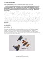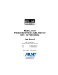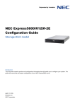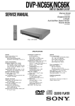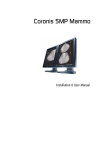
1
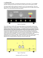
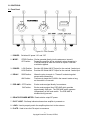
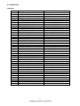
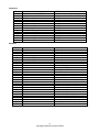
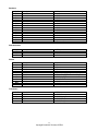
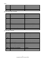
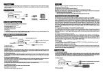
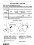
SILTRONIX
MODEL LA-600 RF Amplifier
OPERATING/SERVICE MANUAL
SILTRONIX
330 VIA EL CENTRO
OCEANSIDE, CALIFORNIA 92054
Original manual print date unknown
Copyright 2007 Donald W. Thomas, K5ZRQ
Artwork and Diagrams by Bennie Bolin
1.0 INTRODUCTION:
In putting together this manual, I used what limited information I could compile. The new updated
schematic, drawings and PCB layout were drawn by B. Bolin and were verified against a LA-600.
The Siltronix Model LA-600 is designed for operation in the 26 to 30 megacycle range. Due to the
high efficiency of the “Single Band” design, it is an excellent amplifier for the Ten Meter Amateur Radio
Operator, or for other services outside the United States.
Figure 1-1 Front Panel
The LA-600 features a High/Low RF transmit output selection and a pre-amplifier which provides
approximately 6 db gain on received signals. The LA-600 is designed with the best of components
available to provide years of trouble free service. It is important, however, the Operating Instructions
should be followed. The RF drive requirements to the amplifier should not be exceeded. Once the
unit has been installed and tuned for proper operation, retuning of the amplifier should not be required.
Even though the rugged 8950’s should provide years of trouble free operation, the most severe
conditions for the tubes exist during the tune-up procedure where the possibility of Off-Resonance
condition allows relatively large amounts of current to be drawn through the tubes. Unnecessary tuneups will reduce the life of the 8950’s. Once the unit is properly tuned for operation, major
readjustments should rarely be necessary. Occasional minor touch-up of the “PLATE” tuning to verify
peak performance is recommended. Both “PLATE” and “LOAD” controls may require small
adjustment when changing antennas or switching to and from a dummy load.
Figure 1-2 Rear Panel
2
Copyright Donald W Thomas, K5ZRQ
1.1 SPECIFICATIONS:
Power Ratings:
SSB 800 Watts Nominal PEP Output on High Power
AM 500 Watts Nominal Output on High Power
AM 300 Watts Nominal Output on Low Power
Frequency Coverage:
26.0 to 30.0 MC
Tube Complement:
Four 8950’s in grounded grid and one 8950 Driver in grounded cathode.
RF Drive Requirements:
AM Operation - Nominal 3 Watts
Single Sideband - Nominal 7 Watts PEP
Meter:
Reads relative output RF voltage.
Relay Keying:
In SSB position, automatically switches the amplifier into the “Transmit” mode when SSB
modulation is present. Returns to receive mode after a short delay when no modulation
is present.
In AM position, the AM carrier of the transmitter keeps the amplifier in the
“Transmit” mode as long as the transmitter is keyed.
“PI” Output Circuit:
Matches 52 to 75 ohm load and other impedances where the SWR does not exceed 2.5:1
Pre-Amplifier:
Provides approximately 6 db gain for received signals.
Power Supply:
Computer grade electrolytic capacitors and conservatively rated silicon rectifiers together with a
heavy duty power transformer provide a reliable power source.
AC Input: 117 Volts, 50-60 Hz
Front Panel Controls:
PLATE, LOAD, RELATIVE OUTPUT Meter, Power On Indicator, AC POWER Switch, MODE
Switch, RF POWER Switch, DELAY Switch, PRE-AMP Switch
Rear Panel:
L10 Access Hole, INPUT Jack, OUTPUT Jack, Fuse Holder, GRID TUNING Coil, GROUND Lug
Dimensions:
13” Wide x 5-3/4” High x 10-3/4” Deep
Weight:
27 Pounds
3
Copyright Donald W Thomas, K5ZRQ
2.0 INSTALLATION:
CAUTION: Lethal voltages are present in this amplifier! DO NOT REMOVE the bottom cover or
cabinet while the AC power cord is connected to the wall outlet.
Before removing the covers for any reason, allow at least one minute for the filter capacitors to
discharge after turning amplifier off and disconnecting the AC line cord. Then short the driver and final
plate circuit to ground with an insulated screwdriver before touching any of the components.
1.
Select a location for your amplifier. RF amplifiers need ventilation, so choose a location that will
not restrict the air flow around the amp. While turned on, the unit will generate a lot of heat so do
not lay anything on top of the amplifier.
2.
Do not exceed the nominal input RF drive requirements listed under “Specifications” by more than
15 percent. Check RF output specifications of the exciter (or, measure the power output with a
wattmeter).
3.
Connect a short length of coaxial cable (RG-58 or RG-8) from the exciter (transceiver or
transmitter) to the “INPUT” jack on the rear of the LA-600. A PL-259 connector is required to
connect the coax cable to the amplifier. Coax cable should be as short as possible.
4.
Connect antenna or suitable high power dummy load to the “OUTPUT” connector on the rear of
the LA-600 using RG8/U coax or similar type coax with a PL-259 connector.
5.
The unit should be grounded for R.F. by attaching a ground strap of coaxial shield or 10-12 gauge
wire to the ground post on the amplifier. This should be connected by a short run to a ground rod
or cold water pipe. The idea is to have a short direct earth ground to keep the chassis at radio
frequency ground. In many cases normal operation can be had without such a ground, but a
good ground can help prevent television interference, and make tuning straightforward.
6.
The A.C. line cord should be plugged into a three-wire outlet. The electrical circuit should be
capable of handling a 15 ampere load.
4
Copyright Donald W Thomas, K5ZRQ
3.0 CONTROLS:
3.1 Front Panel
Figure 2-1 Front Controls
1. POWER:
Switches AC power “On” and “Off”
2. MODE:
STDBY Position: Exciter operated directly into the antenna on transmit.
OP Position:
Transmitting amplifier will be switched in when the exciter is
in AM and keyed or when the exciter is keyed in SSB with
modulation applied.
3. POWER:
LOW Position:
HIGH Position:
Provides 300 Watts AM RF Output for the nominal 3 watts input.
Provides 500 Watts AM RF Output for the nominal 3 watts input.
4. DELAY:
SSB Position:
Allows the relay to remain in “Transmit” mode during short
pauses while transmitting.
Continuously keeps the LA-600 in the transmit mode so long
as the exciter is in transmit.
AM Position:
5. PRE-AMP: OFF Position:
ON Position:
Exciter receives signal directly from antenna.
Exciter receives signal from PRE-AMP which provides
approximately 6 db gain. The PRE-AMP switch operates
independently of the mode switch. The PRE-AMP is
disabled during transmit.
6. RELATIVE POWER METER: Reads relative output RF power.
7. PILOT LIGHT: Red lamp indicator shows when amplifier is powered on.
8. LOAD: Used to properly match the amplifier plate circuit to the antenna.
9. PLATE: Used to tune the PA output to resonance.
5
Copyright Donald W Thomas, K5ZRQ
3.2 Rear Panel
Figure 2-2 Rear Controls and Connections
1 AC Line Cord
2 FUSE Holder: Accepts Type 3AG 15 Amp fuse.
3 GRID TUNING: Tunes input grid circuit of the 8950 Driver tube.
4 GROUND: Ground Lug for attaching ground wire from the chassis of the unit to earth ground.
5. C30: Tunes output plate circuit of the 8950 Driver tube.
6 OUTPUT:
Connects RF output of the amplifier to the antenna coax feed line.
7 L10 Access Hole: L10 is for tuning RF input to the Preamp circuit.
8 INPUT:
Connects RF Drive from exciter to input of amplifier.
4.0 OPERATION:
1. Setting the “MODE” switch to the “STDBY” position (or the main “POWER” switch to “Off”) permits
the exciter (transceiver) to operate directly into the antenna. This also allows any adjustment to be
made to the exciter before operating the LA-600. Use this setting for checking drive power.
2. Initial tune-up should be accomplished with the exciter (transceiver) set at the middle range of the
frequencies to be operated. This allows operation over the entire range without re-tuning the
amplifier.
3. The tune-up procedure should initially be accomplished by applying the exciter driving power for
short periods of time, not longer than 30 seconds. Release the push-to-talk button on the
microphone for about 30 seconds between each adjustment. During the final fine adjustments of
the tuning controls the drive may be held on for longer periods, provided only minor adjustments
are made. This method of tune-up will prevent the tubes from overheating during adjustments.
Once the tune-up procedure has been completed, the cooling fan, plus the high quality
components, will provide normal operation indefinitely with only an occasional minor tune-up.
6
Copyright Donald W Thomas, K5ZRQ
4.1 INITIAL TUNE-UP:
Read all of these tune-up instructions before turning the power on or attempting tune-up. It is very
important that the amplifier be properly tuned if it is to provide long life and good performance. Never
operate the amplifier if it is not properly tuned.
1. Set “DELAY” switch to the “AM” position.
2. Set “POWER” switch to the “LOW” position.
3. Set “PLATE” control to “5”.
4. Set “LOAD” control to “5”.
5. Place AC “POWER” switch in the “ON” position. The red pilot light should be on. Always allow at
least one minute warm-up before proceeding with tune-up or operation.
6. Key exciter (transceiver) in transmit mode (AM). If single sideband is the only mode available,
tune-up of the LA-600 can be accomplished by a sustained whistle into the microphone while
holding the push-to-talk button down. In the AM mode, it is only necessary to press the
push-to-talk button on the microphone (do not talk into the microphone in this mode). Either
method will provide the RF drive required for tuning the LA-600.
7. Quickly adjust “PLATE” control for maximum meter reading. There should be a definite maximum
meter reading and as the “PLATE” control is moved in either direction the reading should decrease.
8. Quickly adjust the “LOAD” control for maximum meter reading.
9. Steps #7 and #8 should be repeated several times until no greater reading can be obtained. Do
this as rapidly as possible.
10. Now switch RF “POWER” switch to “HIGH” and repeat Steps #7 and #8 several times until a
maximum reading is again obtained.
11. The “POWER” switch can now be used to select “LOW” or “HIGH” power output.
4.2 OPERATION AFTER TUNE-UP:
AM Operation: “DELAY” switch should be in the AM position. When the exciter (transceiver) is keyed
into the transmit mode, the LA-600 will automatically go into transmit. During AM
modulation a slight downward deflection may be noted on the meter. This is a normal
state and will not affect the audio quality of the transmitted signal.
SSB Operation: “DELAY” switch should be in the SSB position. If there is a long pause between
words during a transmission, the antenna switching relay in the LA-600 will return to
the receive position. Talking into the microphone will automatically return the
antenna switching relay to the transmit position. This relay action is normal.
7
Copyright Donald W Thomas, K5ZRQ
5.0 CIRCUIT DESCRIPTION:
The LA-600 is a classic TV Sweep Tube Amplifier using five 8950 tubes. One of the tubes is a grid
driven driver stage and the other four are the PA tubes in grounded grid final operation. It has a low
and high power output setting and features a pre-amplifier which provides approximately 6 db gain on
received signals.
Figure 5-1 Chassis Layout
In the figure above, you can see the Driver Section in the lower right corner. The variable capacitor
C30 to the right of the Driver tube is for tuning the Driver output and is accessed thru a small hole in
the side of the top cover. The four PA Tubes are just above the driver section. You can see the Plate
Cap connections with their Plate Parasitic Suppressors. Above them you will find the Plate Load and
Plate Tune capacitors used for tuning the finals for proper operation. In the bottom center, K1 is the
main relay for switching the PA in and out of line. K2 is mounted on the PCB and it functions to switch
the Preamp in and out of line as the PA is keyed. To the left is the main Power Transformer. Above it
are the four capacitors that make up the high voltage power supply filter. The Fan in the center of the
chassis runs continuously as long as the Amplifier is turned on providing air circulation for the tubes.
8
Copyright Donald W Thomas, K5ZRQ
6.0 PCB LAYOUT:
The PCB is mounted on the back wall of the amplifier. It contains the Receive Preamplifier Q1,
Transmit detector Q2, Power Amp relay driver Q3, Preamp relay driver Q4, and Relay K2 for switching
the preamp in and out of the circuit. There are 12 points shown in the drawing by a number inside a
circle. These points are connections from the PCB to various points in the LA-600 as indicated by the
labeling.
Figure 6-1 PCB
The wire connections to the PCB are as listed below:
1. Wire from PCB to relay K2 NO contact.
2. Connects to RF Input Jack.
3. Connects to Delay switch SSB contact.
4. Connects one end of R42, the other end of R42 is connected to the RF Output Jack.
5. Connects to the front panel meter.
6. Connects to Preamp switch.
7. Connects to Preamp switch.
8. Connects to the common contact of the Mode switch.
9. Connects to the +16V line.
10. Wire from PCB to relay K2 NC contact.
11. Connects to Relay K1A NC contact.
12. Connects to Preamp switch.
13. Hole on PCB ground trace that is unused.
9
Copyright Donald W Thomas, K5ZRQ
7.0 ALIGNMENT:
ALIGNMENT – LA-550, LA-600, LA-650
This alignment procedure applies to the LA-550, LA-600, and LA-650 amplifiers.
1. Driver Neutralization
A. Connect RF Voltmeter to the cathodes of the four PA tubes. If a RF Voltmeter is not
available, an Oscilloscope with a bandwidth over 30 Mhz can be used with a 10X Probe.
B. With linear amplifier off, key your transmitter, depress relay K-1 with an insulated tool, and
adjust the neutralization trimmer (it is under the driver tube) for a dip or minimum
reading on the RF Voltmeter or Oscilloscope. The amplifier is now neutralized.
2. Bias (Driver)
A. Connect a DC Voltmeter to Pin 2 of the driver tube (the cathode).
B. Turn linear amplifier on, set to high power position.
C. Adjust bias pot (one closest to power supply) for a .5 VDC reading on Pin 2.
3. Bias (Power Amp)
A. Connect DC Voltmeter across the one ohm, 10 watt resistor in the cathode of the power amp.
B. Turn linear amplifier on, set to high power position.
C. Depress relay using insulated tool. Adjust power amplifier bias pot for a .05 reading on your
voltmeter.
4. Tune Up:
A. Adjust Driver Grid Tuning and Plate tune output capacitor for maximum power out.
B. Adjust power amplifier front panel Plate and Load for maximum power out.
10
Copyright Donald W Thomas, K5ZRQ
8.0 PARTS LIST:
Capacitors
Ref#
C1
C2
C3
C4
C5
C6
C7
C8
C9
C10
C11
C12
C13
C14
C15
C16
C17
C18
C19
C20
C21
C22
C23
C24
C25
C26
C27
C28
C29
C30
C31
C32
C33
C34
C35
C36
C37
C38
C39
C40
C41
C42
C43
C44
C45
Description
.01uF Ceramic Disc
.01uF Ceramic Disc
.0022uF Ceramic Disc
.0022uF Ceramic Disc
.0022uF Ceramic Disc
.0022uF Ceramic Disc
225uF 300VDC Electrolytic
225uF 300VDC Electrolytic
225uF 300VDC Electrolytic
225uF 300VDC Electrolytic
100uF 150VDC Electrolytic
100uF 150VDC Electrolytic
250uF 20VDC Electrolytic
.002uF Ceramic Disc
.002uF Ceramic Disc
.002uF Ceramic Disc
.002uF Ceramic Disc
.002uF Ceramic Disc
1.5 – 20 pF Compression Trimmer
50pF Mylar
100uF 250VDC Electrolytic
.002uF Ceramic Disc
.002uF Ceramic Disc
.002uF Ceramic Disc
3.3pF 3KV Ceramic Disc
3.3pF 3KV Ceramic Disc
.002uF 2KV Ceramic Disc
.002uF 2KV Ceramic Disc
270pF 2.5KV Mica, CM35FK271JN3
46pF, Air Variable
120pF, Compression Trimmer
.002uF Ceramic Disc
.002uF Ceramic Disc
.002uF Ceramic Disc
.002uF Ceramic Disc
.002uF Ceramic Disc
.002uF Ceramic Disc
.002uF Ceramic Disc
.002uF Ceramic Disc
.002uF Ceramic Disc
.002uF Ceramic Disc
.002uF 2KV Ceramic Disc
.002uF 2KV Ceramic Disc
270pF 2.5KV Mica, CM35FK271JN3
270pF 2.5KV Mica, CM35FK271JN3
NOTES:
AC Input bypass
AC Input bypass
HV Section
HV Section
HV Section
HV Section
HV Section, CG2250T300B1
HV Section, CG2250T300B1
HV Section, CG2250T300B1
HV Section, CG2250T300B1
Bias Power Supply
Bias Power Supply
LV Power Supply
PA Section V2 socket
PA Section V3 socket
PA Section V4 socket
PA Section V5 socket
Driver Section
Driver Section, Marked 404
Driver Section
HV Section, Bottom chassis term strip
Driver socket pin 11
Driver socket pin 3
Driver socket pin 2
Driver Section
Driver Section
Driver Section
Driver Section
Driver Section
Driver Section, Marked 074-063
PA Section, Marked 302M
PA Section
PA Section
PA Section V2 socket
PA Section V2 socket
PA Section V3 socket
PA Section V3 socket
PA Section V4 socket
PA Section V4 socket
PA Section V5 socket
PA Section V5 socket
PA Section
PA Section
PA Section
PA Section
11
Copyright Donald W Thomas, K5ZRQ
Capacitors
Ref#
C46
C47
C48
C49
C50
C51
C52
C53
C54
C55
C56
C57
C58
C59
Description
105pF, Air Variable, PA TUNE
710pF, Air Variable, PA LOAD
39 pF Ceramic Disc
33 pF Ceramic Disc
.01uF Ceramic Disc
10 pF Ceramic Disc
.01uF Ceramic Disc
.002uF Ceramic Disc
30 MFD 15V Electrolytic
.002uF Ceramic Disc
30 MFD 15V Electrolytic
.002uF Ceramic Disc
.002uF Ceramic Disc
.002uF Ceramic Disc
NOTES:
PA Section
PA Section, Marked 074-062ASP7341
On PCB
On PCB
On PCB
On PCB
On PCB
On PCB
On PCB
On PCB
On PCB, SSB delay cap
On PCB
On PCB
On PCB
Description
470K 1W
470K 1W
470K 1W
470K 1W
39K 6W, DALE FP33 6W
39K 6W, DALE FP33 6W
39K 6W, DALE FP33 6W
39K 6W, DALE FP33 6W
1K 1W
4.7K 1W
4.7K 1W
6.8K 1W
10K 1/2W
12K 10W
10K 10W
100 5W
27K 1W
4.7K 1W
4.7K 1W
47K 1W
47K 1W
47K 1W
47K 1W
100 5W
1 10W
75 20W
47K 1/2W
12K 2W
NOTES:
HV Section
HV Section
HV Section
HV Section
HV Section
HV Section
HV Section
HV Section
Bias Power Supply
VR1 and term strip
Across VR1
Tied to VR1
Driver Section, Bottom chassis term strip
HV Section, Bottom chassis term strip
HV Section, Bottom chassis term strip
Driver Section, Bottom chassis term strip
On bottom chassis terminal strip
By VR2
By VR2
PA Grid resistor V5
PA Grid resistor V4
PA Grid resistor V3
PA Grid resistor V2
Mounted behind Preamp Switch
Mounted behind Preamp Switch
Mounted behind Mode and Power Switch
Mounted by K1
Driver Section
Resistors
Ref#
R1
R2
R3
R4
R5
R6
R7
R8
R9
R10
R11
R12
R13
R14
R15
R16
R17
R18
R19
R20
R21
R22
R23
R24
R25
R26
R27
R28
12
Copyright Donald W Thomas, K5ZRQ
Resistors
Ref#
R29
R30
R31
R32
R33
R34
R35
R36
R37
R38
R39
R40
R41
R42
R43
Description
2.2K 2W
68K 1/2W
1K 1/2W
10K 1/2W
220 1/2W
470 1/4W
22K 1/4W
220 1/2W
6.8K 1/4W
3.3K 1/2W
22K 1/4W
1K 1/4W
15K 1/4W
10K 2W
150 1/2W
NOTES:
Driver Section
On PCB
On PCB
On PCB
On PCB
On PCB
On PCB
On PCB
On PCB
On PCB
On PCB
On PCB
On PCB
One end connected to PCB
On Terminal Strip
Ref#
VR1
VR2
VR3
Description
5K
25K
10K
NOTES:
Bottom Chassis
Bottom Chassis
On PCB
Ref#
D1
D2
D3
D4
D5
D6
D7
D8
D9
D10
D11
Description
1N4822
1N4822
1N4822
1N4822
1N4005
1N4005
1N914
1N4005
1N914
1N4005
1N34A
NOTES:
HV Section
HV Section
HV Section
HV Section
Bias Power Supply, On Terminal Strip
LV Power Supply, On Terminal Strip
On PCB, Keying detector
Across K1
On PCB
On PCB Across K2
On PCB, Meter detector
Description
2N5814
2N5814
2N5814
2N5814
NOTES:
On PCB, Preamp
On PCB, Keying control
On PCB, Relay driver
On PCB, Relay driver
Potentiometers
Diodes
Transistors
Ref#
Q1
Q2
Q3
Q4
13
Copyright Donald W Thomas, K5ZRQ
Tubes
Ref#
V1
V2
V3
V4
V5
Description
8950
8950
8950
8950
8950
NOTES:
Driver Section
PA Section
PA Section
PA Section
PA Section
Switches, Fuses, Relays, Lamp, Misc
Ref#
F1
Description
15 Amp
NOTES:
S1
S2
SPST
SPDT
AC POWER Switch
MODE Switch
S3
S4
S5
DPST
SPDT
DPST
RF POWER Switch
DELAY Switch
PREAMP Switch
K1
K2
K3
3PDT
DPDT
DPDT
Potter Brumfield, 12V, KT11D
AZ531-09-1
LAMP
# 1815
14V 200Ma, 2.8 Watts, T3.25
Top Cover, 8-32 x 1/4” Binder Head
Bottom Cover,
6 each
6 each
SCREW
SCREW
Inductors, RFC, Transformer
Ref#
L1
L2
L3
L4
L5
L6
L7
L8
L9
L10
L11
RFC 1
RFC 2
RFC 3
RFC 4
RFC 5
T1
Description
4 uH
17 uH
55 uH
55 uH
Wire Coil
17 uH
55 uH
Wire Coil
30 uH
Preamp Tuning Coil
GRID TUNING Coil
NOTES:
Filament Choke
Driver Plate HV Choke
Driver Plate HV Choke
PA Cathode Choke
Driver Section, Pi Network
PA Plate HV Choke
PA Plate HV Choke
PA Section, Pi Network
PA Section, Mounted under C49
On PCB, Tunes Preamp Input
Access on back of chassis
47 2W with 4 Turns Metal Strip
100 2W with 5 Turns 14ga Wire
100 2W with 5 Turns 14ga Wire
100 2W with 5 Turns 14ga Wire
100 2W with 5 Turns 14ga Wire
Driver Section
PA Section
PA Section
PA Section
PA Section
Power Transformer
271-025
14
Copyright Donald W Thomas, K5ZRQ
9.0 POWER TRANSFORMER:
USING TRANSFORMER 271-025 (10 LEADS) WITH LA-550, LA-600, and LA-650
The original power transformer used in the LA-550, 600 and 650 series linear amplifiers was the 9
or 8 lead version of the 271-025. If the linear uses 6LF6 tubes it has the 9 lead version, because of
the requirement to provide 6 volts to the filament of the driver tube. If the linear uses 8950 tubes the 8
lead version may have been used as there is no requirement for a 6 volt center tap. The 8950 has a
12 volt filament.
Because the 10 lead version of 271-025 has no 6 volt filament tap it cannot be used to replace the
transformer in a linear with 6LF6 unless a simple modification is performed. This consist of replacing
the driver tube with an 8950 and re-wiring the filament pin (pin #1) to the 12 VAC filament source. The
other socket pin connections remain the same. The driver stage must be re-aligned and reneutralized because the internal capacitances of the two different tube types are not the same.
Also when using the 10 lead transformer, the two primary windings must be wired in parallel. For
the 110V AC source the 2 windings are (1) orange and brown and (2) yellow and green. To wire them
in the proper phase the orange and yellow leads are both connected to the unswitched line cord lead
at the term strip (this is the line cord lead that is not connected to the fuse holder). The green and
brown leads are both connected to the adjacent terminal. This terminal has a wire leading to the
power switch.
10.0 REPAIR TIP:
SWITCH REPAIR TIP
If you have a switch like this and it is being intermittent or not working at all, it probably just needs
cleaning. This is a DPST switch and if you cannot find a suitable replacement, this is how to
disassemble and clean the old one. When removing switch, make sure you remember to identify
which wire connects to which terminal. Word of caution, the AC POWER and the PREAMP switch are
used to secure the front panel to the chassis.
Figure 10-1
15
Copyright Donald W Thomas, K5ZRQ
Disassembly: Carefully drill off the braded end of the two rivets holding the switch together using a
small drill bit. Then push the rivets out of the switch while holding the switch front and back. Once the
rivets are removed, the internal spring will be pushing the switch apart. Lift the top cover off while
watching where all the pieces are located. The picture above shows a switch before repairing and one
disassembled showing all the parts and the two bolts to put it back together with. Remove the three
piece part (cap, spring, and guide) and lay to the side. Remove the brass roller that looks like a mini
dumbbell and clean it to remove any oxidation. Next using a Q-tip and alcohol, clean the contacts
inside the switch housing. It’s possible the bottom contacts have worn down some over time. If so,
the raised track running down the middle of the housing may now be holding the brass roller up
preventing it from making firm connection with the bottom contacts. Using a small knife point, carefully
scrape both sides of the track a small amount by the contacts. You can also scrape down the top a
very small amount. Do not remove much material, just scrape a little off. The track also acts as a wall
between the contacts. This should allow the roller better contact if the track was holding it up.
Reassembly: Put brass roller back into the housing and push it to the end with the side contacts. Put
the three piece part back in with the grooved guide end riding on the middle of the brass roller. Place
the two insulators back on the sides of the housing. Move toggle on top cover to the side labeled “ON”.
While holding the housing and insulators together, slide the top cover down over the housing. The
bottom of the toggle lever fits into the top plastic cup of the three piece part as it goes together. If you
have it backwards, the “ON” position will be “OFF”. Just turn the top around if needed to put it right.
Two small nails that will fit thru the holes will hold it together while finishing up. You can check the
“ON and “OFF” with an ohmmeter at this point easily. The two bolts and nuts needed to replace the
rivets are size 2-56. The bolt is 2-56 x 3/4in. The bolts will fit the holes in the top cover, but will have
to be threaded thru the housing. Remove one of the nails and insert a bolt. Screw it in all the way
down and watch the housing bottom as you tighten it. You only want to tighten enough to barely
compress the housing. Place a nut on the end and tighten only enough to barely compress the
housing from that side. If tightened too much, you may distort the housing where the brass roller may
bind and not move freely. Now put in the other bolt and nut. Tighten the same way. You only need
them snug to hold the switch together properly. Verify the switch is working properly. You can use a
drop of nail polish to secure the nuts if needed.
16
Copyright Donald W Thomas, K5ZRQ
Of course, no manual would be complete without the manufacturer’s equipment warranty.
WARRANTY POLICY
SILTRONIX CORPORATION warrants, to the original purchaser, this equipment to be free of defects
in material or workmanship, except for tubes, transistors and diodes, under normal service for a period
of six months from the date of original purchase. Tubes, transistors and diodes are covered under the
warranty policy for a period of 90 days. This warranty is valid only if the enclosed card is properly
filled out and mailed to the factory within ten days of purchase.
Do not ship equipment to the factory without prior authorization. This warranty is limited to repairing or
replacing only the defective parts, and is not valid if the equipment has been tampered with, misused,
or damaged. All returns for repairs must be freight prepaid. This equipment is manufactured for use
on such frequencies as authorized by the FCC. Siltronix does not accept any responsibility for
un-authorized use of such equipment.
17
Copyright Donald W Thomas, K5ZRQ