1
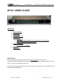
Preliminary Manual
840-08596-01
RELAY BOX - RB132/GP132 USER’S GUIDE
GP132 USER’S GUIDE
CONTENTS
q
q
q
q
q
q
q
q
PACKAGE CONTENTS
INTRODUCTION
INSTALLATION
CONNECTOR PIN OUTS
SETUP THE UNIT
q FADER START
q
TRACK ARMING (RECORD READY SELECT) FOR THE MULTI TRACK MACHINE
q MUTE ON/ OFF CONTROLLED BY TALLY SIGNAL
THEORY OF OPERATION
q HOW TO REPLACE THE EPROM
APPENDIX -1
SPECIFICATIONS
IMPORTANT
Before installing this equipment, please read the INSTALLATION section on page 3.
An improper cabling configuration can potentially cause damage to the internal components of this
device, or devices connected to the GP-132.
If you have any questions, please contact your local service representative or our customer service
department (650-855-0400).
EUPHONIX INC - RB132/GP132
p1
Wednesday, August 26th , 2000
Preliminary Manual
RELAY BOX - RB132/GP132 USER’S GUIDE
PACKAGE
This package contains :
1. One GP132.
2. One 8 foot Power cable.
3. One User’s guide.
Introduction
The GP132 is a multiple purpose relay box which can perform several functions.
1. It can provide the CS2000/3000 system with a Track Arming unit, for professional Tape
Machines such as MTR90, A820, A827, PCM3324, PCM3348, and many others.
2. The GP132 is a micro-processor based MIDI Machine Control to Serial (Studer) and parallel
relay closures system. It provides up to 32 channels per unit, or this could be viewed as 24 channels
+ 8 additional relays for parallel transport control, sync repro switching etc.
3. It can also perform more menial tasks, such as that of a general purpose output / input event
system - giving access to 32 relay closures and switched inputs. These could even be timed events,
creating a powerful, theatre based, synchronized event system, running to MTC or P2 protocols.
The GP132 is addressable and could allow up to 255 units to work together - giving a total of 8,160
relays and inputs.
EUPHONIX INC - RB132/GP132
p2
Wednesday, August 26th , 2000
Preliminary Manual
RELAY BOX - RB132/GP132 USER’S GUIDE
Installation
25-pin Dsub connector RT1 – RT4
Each connector has 8 relay outputs and 8 tally inputs. Both outputs and inputs share common lines,
so special care is required when multiple devices are connected to the same connector.
Tally inputs will accept from 5 volts to 24 volts, both DC and AC. Please contact Euphonix Customer
Service if you are planing to apply over 24 volts.
The relays used in this unit are rated at 500mA maximum. An additional driver circuit is required to
drain more current beyond this rating.
Connecting to a CS2000 / CS3000 series Mixing Console
The GP132 is connected to a CS2000/CS3000 with a MIDI cable. Currently, there are two ports
available for the GP132. Which port you will be using depends on what job you want the GP132 to do.
Method One is to connect to the DSC MIDI port which is located under the Mix Controller. This
allows 16GPI triggers known as fader starts and Track Arming for the Multi-Track Recorder or
dubber, etc.
Method Two is to connect the GP132 MIDI in/out to port#3 on the MIDI EXPRESS interface unit.
In this way, GP132 can control the desk or be controlled from the desk by using Note On/Off
messages and/or Continuous Controller (C.C) messages. When Continuous Control is used, the
console parameters such as fader level, pan, aux levels will work between fully minimum or fully
maximum, since the GP132 sends/receives MIDI value zero or 127. Special caution must to be
taken when using C.C.mode because of this.
The description of how to configure the desk is described in the CS3000 Operation Manual Version
3.0 page-12 – 7 to 12-9 for external control. Fader starts are described in the MixView Software
Supplement Version 3.0 Revision 2 page 10 – 70. they are also described in the
Euphonix MX464 Operation & Service Manual 1 – 16 and 1-17, since the GP132 is working in MX464
simulation mode, in this case.
This manual contains these related sections from the above referenced manuals in the APPENDIX
section.
EUPHONIX INC - RB132/GP132
p3
Wednesday, August 26th , 2000
RELAY BOX - RB132/GP132 USER’S GUIDE
Preliminary Manual
CONNECTOR PIN OUTS
RT1
RELAY OUTPUT
Relay-1
Relay-2
PIN NUMBER
2
16
TALLY INPUT
Tally-1
Tally-2
PIN NUMBER
1
15
Relay-3
Relay-4
Relay-5
Relay-6
Relay-7
5
19
8
22
11
Tally-3
Tally-4
Tally-5
Tally-6
Tally-7
4
18
7
21
10
Relay-8
25
Tally-8
Relay out common
13
Tally in common
NOTE: Pin 3,6,9,12,14,17,20 and 23 are connected internally.
24
3,6,9,12,14,17,20,23
RT2
RELAY OUTPUT
PIN NUMBER
TALLY INPUT
PIN NUMBER
Relay-9
Relay-10
Relay-11
Relay-12
2
16
5
19
Tally-9
Tally-10
Tally-11
Tally-12
1
15
4
18
Relay-13
Relay-14
Relay-15
Relay-16
8
22
11
25
Tally-13
Tally-14
Tally-15
Tally-16
7
21
10
24
Relay out common
13
Tally in common
NOTE: Pin 3,6,9,12,14,17,20 and 23 are connected internally.
EUPHONIX INC - RB132/GP132
p4
3,6,9,12,14,17,20,23
Wednesday, August 26th , 2000
RELAY BOX - RB132/GP132 USER’S GUIDE
Preliminary Manual
RT3
RELAY OUTPUT
Relay-17
Relay-18
Relay-19
PIN NUMBER
2
16
5
TALLY INPUT
Tally-17
Tally-18
Tally-19
PIN NUMBER
1
15
4
Relay-20
Relay-21
Relay-22
Relay-23
19
8
22
11
Tally-20
Tally-21
Tally-22
Tally-23
18
7
21
10
Relay-24
25
Tally-24
Relay out common
13
Tally in common
NOTE: Pin 3,6,9,12,14,17,20 and 23 are connected internally.
24
3,6,9,12,14,17,20,23
RT4
RELAY OUTPUT
Relay-25
PIN NUMBER
2
TALLY INPUT
Tally-25
PIN NUMBER
1
Relay-26
Relay-27
Relay-28
Relay-29
16
5
19
8
Tally-26
Tally-27
Tally-28
Tally-29
15
4
18
7
Relay-30
22
Tally-30
Relay-31
11
Tally-31
Relay-32
25
Tally-32
Relay out common
13
Tally in common
NOTE: Pin 3,6,9,12,14,17,20 and 23 are connected internally.
S1 RS-422
21
10
24
3,6,9,12,14,17,20,23
S2/S3 -NET
Pin number
Signal
S2 Pin #
S3 Pin #
Signal
1
2
3
4
GND
RX TX +
GND
1
2
3
4
1
2
5
6
+5v
+5v
RxD RxD +
5
6
7
8
N/C
GND
RX +
TX -
5
6
7
8
3
4
7
8
TxD TxD +
GND
GND
9
GND
9
10
9
10
GND
GND
EUPHONIX INC - RB132/GP132
p5
Wednesday, August 26th , 2000
RELAY BOX - RB132/GP132 USER’S GUIDE
Preliminary Manual
SETTING
UP THE
UNIT
VER 0.4H
FIRMWARE
The GP132 has a three way toggle switch on the right of the front panel.
It has three states :
q
Relays only
q
Relays + Tallies
q
Setup
1.
MIDI
(UP)
Displays the state of the RELAY CLOSURES (OUTPUTS) and allows
control of the RELAY CLOSURES (OUTPUTS) manually from the front panel.
Displays the state of the TALLY OPTO' (INPUTS) and allows
setting of the RELAY CLOSURES (OUTPUTS) manually from the front panel.
(CENTRE)
Displays the operational modes of the GP132 and
allow altering of the operational parameters.
PRESS
DOUBLE PRESS
2.
MMC
PRESS
DOUBLE PRESS
3.
N.O.
PRESS
DOUBLE PRESS
4.
C.C.
PRESS
DOUBLE PRESS
5.
(DOWN)
SysX
PRESS
Select MIDI. This de-selects both Sony 9pin & EsBus protocols.
Display & Set MIDI Channel number.
Enable / disable MIDI MACHINE CONTROL. If all other MIDI modes are
disabled at the time that MMC is enabled, then the RELAY and TALLY maps
will be fully set to MMC.
Display & Set R ELAY (OUTPUT) Map for MMC.
Enable / disable MIDI NOTE ON / OFF. . If all other MIDI modes are
disabled at the time that NOTE ON /O FF is enabled, then the RELAY and TALLY
maps will be fully set to NOTE ON /O FF.
Display & Set R ELAY (OUTPUT) Map for NOTE ON /OF F.
Enable / disable MIDI CONTINUOUS CONTROLLERS . . If all other MIDI
modes are disabled at the time that CONTINUOUS CONTROLLERS is enabled,
then the RELAY and TALLY maps will be fully set CONTINUOUS CONTROLLERS .
Display & Set R ELAY (OUTPUT) Map for CONTINUOUS CONTROLLERS .
Enable / disable MIDI SYSTEM EXCLUSIVE. . If all other MIDI modes
are disabled at the time that SYSTEM EXCLUSIVE is enabled, then the RELAY
and TALLY maps will be fully set to SYSTEM EXCLUSIVE. (Currently this mode will work as
an MX464 simulation and ignore all mapping!! ).
DOUBLE PRESS
Display & Set R ELAY (OUTPUT) Map for SYSTEM E XCLUSIVE.
6.
P2
PRESS
Select Sony 9pin protocol (P2) (not available). This de-selects MIDI.
7.
EsBus
PRESS
Select EsBus protocol (EsBus) (not available). This de-selects MIDI.
8.
EAddr
PRESS
no function.
9.
.
PRESS
no function.
DOUBLE PRESS
EUPHONIX INC - RB132/GP132
Display & Set TALLY OPTO'
(INPUT ) Map
p6
for MIDI MACHINE CONTROL.
Wednesday, August 26th , 2000
RELAY BOX - RB132/GP132 USER’S GUIDE
Preliminary Manual
10. .
PRESS
DOUBLE PRESS
11.
.
PRESS
DOUBLE PRESS
12. .
PRESS
DOUBLE PRESS
13. .
14. .
15. .
no function.
Display & Set TALLY OPTO'
(INPUT ) Map
for MIDI NOTE ON / O FF.
(INPUT ) Map
for MIDI CONTINUOUS CONTROLLERS .
(INPUT ) Map
for MIDI SYSTEM E XCLUSIVE.
no function.
Display & Set TALLY OPTO'
no function.
Display & Set TALLY OPTO'
PRESS
no function.
PRESS
no function.
PRESS
no function.
PRESS
Reset all RELAY CLOSURES (OUTPUTS).
HOLD
…at the same time as holding down buttons 14 & 15 will reset the GP132
17. Net
PRESS
Enables Net ports (not available).
18. NAddr
PRESS
no function.
PRESS
no function.
PRESS
no function.
PRESS
no function.
16. Clear All
19. .
20. .
21. .
Display ALL mapping ( MMC / N.O. / C.C. / SysEx ). Displays in sequence Relay
mapping followed by Tally mapping. Combinations of LEDs flash to show
which map is being displayed. (try it!).
22. .
PRESS
23. 24T
PRESS
24. 32T
PRESS
25. 48T
PRESS
26. 64T
PRESS
27. 96T
PRESS
Sets
Sets
Sets
Sets
Sets
28. S/R
PRESS
no function.
29. T:pulse
PRESS
Enables latching TALLY OPTO' (INPUTS) (not available).
30. T:-ve
PRESS
Inverted TALLY OPTO' (INPUTS).
31. R:pulse
PRESS
Enables pulsed RELAY CLOSURE (OUTPUT ) (not available).
track-arming
track-arming
track-arming
track-arming
track-arming
to
to
to
to
to
24
32
48
64
96
(not available).
(not available).
(not available).
(not available).
(not available).
Pulse duration can be set at the console.
32. R:-ve
PRESS
EUPHONIX INC - RB132/GP132
Enables "Normally Closed" RELAY (OUTPUT).
p7
Wednesday, August 26th , 2000
Preliminary Manual
RELAY BOX - RB132/GP132 USER’S GUIDE
FADER START
1.
2.
3.
4.
5.
Connect a MIDI cable from the DSC MIDI OUT (under the Mix Controller) to the GP132
MIDI INPUT.
Put the GP132 into Setup mode, using the front panel toggle switch.
Select MIDI and SysEx by pressing buttons 1 and 5 on the GP132 front panel.
Put the GP132 back to either “Relay Only” mode or “Relay and Tally” mode, using the front
panel toggle switch.
Configure the DSC for fader starts. > See page 13-18.
IMPORTANT NOTE: After setup is done, move all faders assigned as the fader start
up and down a couple of times to complete the fader start enable process.
TRACK ARMING (RECORD READY SELECT) FOR MULTI TRACK MACHINES
1.
2.
3.
4.
Connect the MIDI cable from the DSC MIDI OUT (under the Mix Controller), to the
GP132's MIDI INPUT.
Put the GP132 into Setup mode, using the front panel toggle switch.
Select MIDI and MMC by pressing buttons 1 and 2 on the GP132 front panel.
To enable Rec ready, press the REC button on the far right side of the DSC, then
press the desired track buttons. > See page 18 for the DSC Record and Track arm keys.
TRACK ARMING (RECORD READY SELECT) WITH THE TT-007
1.
2.
3.
4.
5.
Connect a MIDI cable from DSC's MIDI OUT (under the Mix Controller) to the GP132's
MIDI INPUT.
Connect another MIDI cable from the GP132's THRU to the TT007's MIDI IN.
Connect another MIDI cable from the TT007's MIDI OUT to the DSC's MIDI IN.
Select MIDI and MMC by pressing buttons 1 and 2 on the GP132 front panel.
To enable Rec ready, press the REC button on the far right side of the DSC, then press the
desired track buttons. > See page 18 for the DSC Record and Track arm keys.
MUTE ON /OFF CONTROLLED BY TALLY SIGNAL
1.
2.
3.
4.
Connect a MIDI cable from the MIDI IN port #3 (on the back of the MIDI EXPRESS
interface box), to the GP132’s MIDI output.
Select MIDI and N.O. by pressing buttons 1 and 3 on the GP132 front panel.
Put GP132 into “ Relay and Tally” mode, using the front panel toggle switch.
Configure the DSC to receive MIDI N.O. messages. > See page 10-12.
NOTE: Midi number start from zero, so that Relay 1 of the GP132 is Control number 0, Relay 2 is
control number 1 and so on. Same with the Tally numbers. The control numbers on the CS3000 desk
set-up start from zero. For example, if you want to control mute on the channel 5 from Tally 2
input, enter control number “1” (Tally 2) as the control number for the channel 5 mute. Always
subtract one from the GP132’s front panel number when determining the control number for console
set-up.
EUPHONIX INC - RB132/GP132
p8
Wednesday, August 26th , 2000
Preliminary Manual
RELAY BOX - RB132/GP132 USER’S GUIDE
NOTES ON GP132 OPERATION
The GP132 has a bi-directional MIDI control port, however, MMC and SysEx are single directional
and are received by the GP132. When you use this unit for track arming or fader starts, the GP132
receives MIDI commands and then activates relays. Therefore, if something wrong with MIDI
connection or if the GP132 power is off, there is no way for the console to know that the GP132 is
not being controlled properly.
The buttons (1-32) on the GP132 front panel are assigned from MIDI messages 0-31. This is fixed
and can’t be changed.
The GP132 contains battery backed up RAM (memory). It physically lives on the LUMP board. The
unit can operate from RAM or the EPROM. The software can be upgraded by downloading firmware
into the GP132's RAM, using a computer with a serial communication port. Therefore, it is possible
that the GP132's current software (running from RAM) is newer than the version written on the
EPROM label.
Please contact Euphonix Customer Service for the latest firmware upgrades.
HOW TO REPLACE THE EPROM
An EPROM is a static sensitive component. Before remove the EPROM, touch a large metal or grounded object, such as rack
frame. Make sure the power cable is unplugged. Do not remove the LUMP board from the main board, when removing the
EPROM.
Place the new EPROM in the same place. Position pin1 to near the U2 silk screen. Placing the EPROM backwards will damage
the EPROM.
The GP132 boots up and runs it's program from the
battery backed RAM. Installing a new version EPROM
won’t take effect until the RAM is cleared.
To Clear RAM memory, Remove the top cover of the
enclosure. Turn the unit ON. While the unit is running,
short the WD pin and the 0V pin for a moment. These are
located on the LUMP board (as shown).
The unit will then clear the memory and restart itself.
When LEDs on the front panel start cycling, the RAM has
been cleared and the reboot was successful.
EUPHONIX INC - RB132/GP132
p9
Wednesday, August 26th , 2000
Preliminary Manual
RELAY BOX - RB132/GP132 USER’S GUIDE
APPENDIX-1: Reference section of the Console manual
Operation Manual Version 3.0 Revision CS3000
SECTION 12 : MIDI REMOTE CONTROL................... 12 – 7 to 12-9
Remote Control of
External
Equipment (OUT)
You can continuously control external MIDI equipment using group master
faders & mutes via port 3 of the console’s MIDI interface box. (Refer to your
equipment operation manuals for information on making connections.) Any
device that can be addressed by and interpret continuous control MIDI data,
can be controlled. You could for example, control the pitch shift of a synthesizer
or adjust the decay of a reverb unit directly from the console in real time.
Using fader automation, these parameters can be automated to timecode.
From the top level MIDI menu, press [F2] to display the MIDI Out screen and
associated SmartDisplay menu:
The MIDI continuous control OUT screen consists of seven (7) columns
representing the MIDI parameters which must be set in order to successfully
communicate with external equipment. Later in this chapter when we discuss
MIDI continuous control IN, (control of console objects by external equipment),
we will refer back to this list as the following descriptions contain common
references to both features. Refer to the side note for adjustment methods.
The column headings are defined as:
Console Object: In the case of the MIDI Out screen, this column represents
those console objects capable of controlling external MIDI devices.
For the MIDI In screen, this column represents those console objects
capable of being controlled via MIDI data from external sources. (S)
Console Chan: Designates the console channel of the selected console
object. (Na/Nc)
EUPHONIX INC - RB132/GP132
p10
Wednesday, August 26th , 2000
Preliminary Manual
RELAY BOX - RB132/GP132 USER’S GUIDE
MIDI Chan: Designates MIDI Chan: Designates what MIDI channel is to
be used for the communication between the console and the external
device. (Na/Nc)
Control Num: Designates the control number which the selected console
object will send out (or respond to). (Na/Nc)
MIDI Mode: In the case of the MIDI Out screen, designates whether the
console is currently sending MIDI data (OUT) or not active (OFF). For the
MIDI In screen, designates whether the console object is paying attention
to incoming MIDI data (IN) or ignoring incoming data (OFF). (S/F)
Invert: Designates whether the control action is reversed from normal.
For example, if a fader object is being used to control the level on a
synth, setting this parameter will decrease the synth’s level as the
console fader is raised. (S/F)
MIDI Width: Designates the resolution with which MIDI control is
accomplished. The choices are 7bit (128 steps - default) and 14bit (256
steps). Doubling the resolution halves the number of available Control
Nums. (S/F)
The DSC [left arrow] and [right arrow] keys move the cursor horizontally
between columns at any time. To illustrate this, press the [right arrow] key:
It is left as an exercise to the user to explore selecting other fields and adjusting
those parameters.
If you need to control more than one external piece of MIDI gear using the
same type of console object, press the [Enter] key to duplicate templates from
the currently selected console object:
EUPHONIX INC - RB132/GP132
p11
Wednesday, August 26th , 2000
Preliminary Manual
RELAY BOX - RB132/GP132 USER’S GUIDE
In this case, the Lower Group Master has been duplicated three times. Notice
that the MIDI Mode field defaults to active (OUT). These copies can then be
independently configured. To delete any selected duplicates, press [Del].
Remote Control of
Console Objects
by External
Equipment (IN)
You can also continuously control console objects using external MIDI equipment
via port 3 of the console’s MIDI interface box.
From the top level MIDI menu, press [F1] to display the MIDI In screen:
Unlike the MIDI Out feature, there are many more console object choices
capable of being controlled by external signals. (The above screen shows only
a portion of the entire list of controllable console objects.) Column headings
are identical and operation is similar to those of the MIDI Out screen so refer
to the column descriptions listed under the MIDI Out heading discussed
earlier. As before, template copies of any console object are added or deleted
using the [Enter] and [Del] keys respectively.
EUPHONIX INC - RB132/GP132
p12
Wednesday, August 26th , 2000
RELAY BOX - RB132/GP132 USER’S GUIDE
Preliminary Manual
MixView Software Supplement Version 3.0 Revision 2
SECTION 10 : MX464
Pulsed GPI
Switching
GPI control has been enhanced in v3.0 software through the addition of the
pulsed GPI control parameters. Each GPI relay can be set for pulsed (momentary
y) operation. Additionally , this behavior can be set to operate in either or
both fader movement directions and for selectable timing intervals (pulse
width) from 20mS - 2.54s. From the top level SmartDisplay menu, press [F3]
twice to display the GPI menu and screen:
System-wide GPI
Relay and
Speaker
mutes
MX464 GPI relays and speaker mutes are now configured ‘system-wide’
and only the assignment to faders is title-specific. The initialize (reset)
state, action state and pulse width timing of a relay or speaker mute do
not change when a title is loaded or saved.
This system-wide data is stored in the DSC’ s batter y-backed RAM and
is not dependent on the PC. Once set, these settings should never need
attention unless the lithium cell fails or the DSC module is replaced.
EUPHONIX INC - RB132/GP132
p13
Wednesday, August 26th , 2000
Preliminary Manual
RELAY BOX - RB132/GP132 USER’S GUIDE
Column names and their functions are as follows:
• RELAY: The relay number being addressed.
• INIT: The state to which a relay is set when initialized or reset.
• TRIGGER: The fader object controlling the relay .
• STATE: The “active” position of the relay when triggered by the upward
movement of the fader object.
• COMMENT: The name of the relay assigned by either the console or the
user.
The DSC [+] / [-] keys are used to move vertically within columns to
select/address any GPI relay . The DSC [left arrow] and [right arrow] keys
move the selection horizontally from column to column.
To assign a fader object to a relay , select the relay and press a fader object's
attention key:
The selected fader object appears in the TRIGGER field. To clear any fader
object designation, press [Clr] and then [F3] (Yes).
As you may have noticed, it is not necessary to first select the TRIGGER field
in or der to assign the fader object. The INIT and STATE fields operate in a
similar manner when pressing F2 and F3.
EUPHONIX INC - RB132/GP132
p14
Wednesday, August 26th , 2000
Preliminary Manual
RELAY BOX - RB132/GP132 USER’S GUIDE
As with MIDI and Fader -Linking screens, the [Enter] key duplicates the
currently selected GPI object allowing it to be controlled from multiple faders.
Press [F2] to sequence through the available INIT and STATE parameter
settings and observe the DSC screen:
It is advisable to set the INIT field first and then set the STATE field as the for
mer always resets the latter to a default when subsequently accessed again.
Press [ F4] if you wish to modify the STATE column.
The last two screens show the pulsed relay icons and settings. Pulsed
operation means that the relay or speaker mute enters its “active”
state only for the period of time stipulated by the timing figure. Notice the
double-ended arrow in the TRIGGER column next to the fader object
designator . This means that the relay operation is active in both fader
movement directions. To change this to single direction operation, press
[ F3]. The pulse timing can only be changed by first selecting the ST ATE
column using the [ left arrow] or [ right arrow] keys. The SpinKnob is then used
to change the timing figure.
Assigning
Custom GPI
names
Custom GPI names may be assigned by first selecting the desired GPI COMMENT column. The console’ s QWERTY keyboard can then be used to assign
a custom name in place of the default name (RELA Y 1, RELA Y 2, etc.).
A “Clear” key has been added to the DSC Mon Cnfg/Pg 3 upper left display .
This can be used to reset everything in the MX464, including Monitor
assignments, with the exception of the GPI relays.
EUPHONIX INC - RB132/GP132
p15
Wednesday, August 26th , 2000
Preliminary Manual
RELAY BOX - RB132/GP132 USER’S GUIDE
Euphonix MX464 Operation & Service Manual
GPI Relays
With the GP132, any of a set of 16 relays can be actuated from a channel fader
movement or “Fader start” .as it is sometimes called. The relays can be set to
open or close when a fader is moved from the bottom of its travel.
From the top level SmartDisplay menu, press [F3] (Auto) then [F3] (GPI).
On the DSC Screen Display you will see the GPI assignment screen. There are
S
t
a
t
e
o
f
t
h
e
r
e
l
a
y
(
d
e
s
i
g
n
a
t
e
d
a
s
16 relays available. From this screen you will configure the Initial State & On
State
n
of the relay (designated as normally opened or normally closed) and
o
select
the channel fader that will activate the relay. Several relays can be
r
activated
by one channel fader. The speaker mute relays can be activated by a
channel
m
fader start as well. These relays are configured from the same screen
a in a similar manor as the 16 GPI relays. The Initial State and On State for
and
l
these
relays is designated as Mute On or Mute Off .
l
y
EUPHONIX INC - RB132/GP132
p16
Wednesday, August 26th , 2000
Preliminary Manual
Configure GPI Relays
RELAY BOX - RB132/GP132 USER’S GUIDE
Follow the steps below to configure any relays between 1 and 16 :
1. From the GPI screen, use the SpinKnob to select the relay to configure.
The designated relay is displayed above F1;
2. Using the [F2] and [F4] SmartDisplay function keys, set the Initial and On
States of the designated relay;
3. Press the attention key of the fader that you want to control the relay.
The fader assignment will be displayed in the SmartDisplay above F3.
Press [F3] to toggle the fader assignment on or off;
4. Use the SpinKnob to select another relay to configure;
5. Repeat steps 2 - 4.
Single GPI Relay/Multiple Fader
It is also possible to trigger a single GPI relay from many faders. The following
steps allow you to configure this arrangement:
1. Make sure you are in the GPI screen in the Graphics Display;
2. Select the desired relay using the SpinKnob;
3. Press the [Enter] key to create as many relays duplicates as desired.
Alternately, you can press the [Del] key to delete selected duplicates;
4. Select a relay duplicates and assigns a fader by pressing that fader’s
Attention key;
5. Repeat step 4 as desired for all relay duplicates.
To reset the entire GPI assignment display to default settings, press the [Clr]
key and then the [*/ST] key.
Initial State Options
There are three relay initialization options available from the SmartDisplay
menu. From the GPI SmartDisplay menu, press [F1].
The three allow you to:
1. F2 sets the relay to its initial state regardless of the fader position.
2. F3 sets all relays to their initial state.
3. F4 determines weather the relays will initialize when a Title is loaded or
not. In the SmartDisplay if the light next to “Load” is on, the relays will
EUPHONIX INC - RB132/GP132
p17
Wednesday, August 26th , 2000
Preliminary Manual
RELAY BOX - RB132/GP132 USER’S GUIDE
initialize upon Title load. If the light is off, the relays will stay in their
current state after a Title load. The faders must be moved back down to
their stops to initialize them. The default setting is Load on.
EUPHONIX INC - RB132/GP132
p18
Wednesday, August 26th , 2000
Preliminary Manual
RELAY BOX - RB132/GP132 USER’S GUIDE
SPECIFICATIONS
OPERATING VOLTAGE : 100V-240VAC 50/60HZ AUTO RANGING
POWER COMSUMPTION: 15 W MAX.
DIMENSIONS: 19.0” (W ) X 1.73” (H) X 6.42” (D)
485mm (W ) X 44mm (H) X 163mm (D)
WEIGHT: 3.5LBS (1.6KG )
Maximum Relay Current : 500mA
Maximum Relay Voltage : 200V DC
Maximum Relay Power : 10W (Total)
Tally voltage range:
Min: 5V Max:24V
Specifications are subject to change without notice.
EUPHONIX INC - RB132/GP132
p19
Wednesday, August 26th , 2000