1
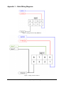
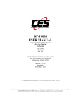
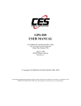
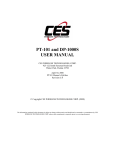
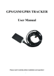
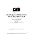
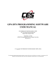
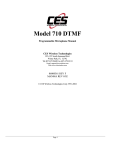
GPS-201 and GPS-202 USER MANUAL CES WIRELESS TECHNOLOGIES, CORP. 925-122 South Semoran Boulevard Winter Park, Florida 32792 October 1, 2010 GPS201-202 Manual v1p1.doc Revision 1.1 © Copyright CES WIRELESS TECHNOLOGIES CORP. (2010) The information contained in this document is subject to change without notice and should not be construed as a commitment by CES WIRELESS TECHNOLOGIES CORP. unless such commitment is expressly given in a covering document. REGULATORY COMPLIANCE FCC The GPRS modem was tested and certified to meet FCC Parts 15 in a stand-alone configuration, which demonstrated that it complies with Part 15 emission limits. The GPS-201/202 uses an Enfora manufactured GPRS modem. FCC Part 22 & Part 24 is covered by the "modular approval" process for a transmitter. This approach, described by FCC Public Notice DA 00131407 released June 26, 2000, is intended to afford relief to equipment manufacturers by eliminating the requirement for obtaining a new equipment authorization for the same transmitter when installed in a new device. In order to approve it without additional FCC certification approvals, the installation must meet the following conditions: For the transmitter to meet the MPE categorical exclusion requirements of 2.1091, the ERP must be less than 1.5 watts for personnel separation distance of at least 20 cm (7.9 in). Therefore, the maximum antenna gain cannot exceed +3.3dBi. If greater than 1.5 watts exists, then additional testing and FCC approval is required. R&TTE The GPRS modem has been fully tested and complies with all the requirements of EN301 489-1, EN301 489-7 and EN60950-1:2001. Compliance to EN301 511 has been demonstrated by testing on the GPS-201/202. Disclaimer The information and instructions contained within this publication comply with all FCC, GCF, PTCRB, R&TTE, IMEI and other applicable codes that are in effect at the time of publication. The GPS-201/202 uses an Enfora manufactured GPRS modem. CES Wireless Technologies disclaims all responsibility for any act or omissions, or for breach of law, code or regulation, including local or state codes, performed by a third party. CES Wireless Technologies strongly recommends that all installations, hookups, transmissions, etc., be performed by persons who are experienced in the fields of radio frequency technologies. CES Wireless Technologies acknowledges that the installation, setup and transmission guidelines contained within this publication are guidelines, and that each installation may have variables outside of the guidelines contained herein. Said variables must be taken into consideration when installing or using the product, and CES Wireless Technologies shall not be responsible for installations or transmissions that fall outside of the parameters set forth in this publication. CES Wireless Technologies shall not be liable for consequential or incidental damages, injury to any person or property, anticipated or lost profits, loss of time, or other losses incurred by Customer or any third party in connection with the installation of the Products or Customer's failure to comply with the information and instructions contained herein. © CES Wireless Technologies Corp – 2010 Page 2 of 12 CHANGE LOG Date 2010-08-05 2010-10-01 Author Doug Hamilton Doug Hamilton Description Initial Release (1.0) Added description of the LEDs in Section 1.6 © CES Wireless Technologies Corp – 2010 Page 3 of 12 TABLE OF CONTENTS REGULATORY COMPLIANCE.................................................................................................................2 CHANGE LOG .............................................................................................................................................3 TABLE OF CONTENTS ..............................................................................................................................4 1.0 Introduction....................................................................................................................................5 1.1 About the GPS-201/202.................................................................................................................5 1.2 About This Manual ........................................................................................................................5 1.3 Basic Package Contents .................................................................................................................5 1.4 Accessories ....................................................................................................................................5 1.5 System Requirements.....................................................................................................................5 1.6 GPS-201/202 Front and Back View ..............................................................................................5 2.0 Specifications.................................................................................................................................7 2.1 System Information........................................................................................................................7 2.2 GPRS Packet Data .........................................................................................................................7 2.3 GPS Functionality..........................................................................................................................7 2.4 Environment...................................................................................................................................7 2.5 Certifications..................................................................................................................................7 2.6 SIM Card/Interface/I/O..................................................................................................................7 2.7 Power .............................................................................................................................................7 3.0 Installation .....................................................................................................................................8 3.1 Mounting Dimensions....................................................................................................................8 3.2 Installing Cables ............................................................................................................................8 3.2.1 HRNS057 - 8-Pin I/O Connector........................................................................................9 3.3 Installing the SIM (Subscriber Identity Module) Card ..................................................................9 3.4 Connecting Power........................................................................................................................10 4.0 Support.........................................................................................................................................11 Appendix 1 – Cable Wiring Diagrams ........................................................................................................12 © CES Wireless Technologies Corp – 2010 Page 4 of 12 1.0 Introduction The GPS-201 and GPS202 are some of the smallest and most economical GPS asset tracking devices available today. GPS and event data is made available on-board the GPS-201/202 for transmission to FleetLinc (CES web based subscriber fleet management service). Models are market specific and may not operate in certain countries. Consult CES for specific country by country information. 1.1 About the GPS-201/202 The GPS-201/202 is an Automated Vehicle Locating (AVL) device that utilizes a GSM/GPRS cellular modem and a Global Positioning Satellite (GPS) module. Working together, these technologies allow the GPS-201/202 to simultaneously act as a stand alone GPS reporting device and wireless data retrieval unit. The GPS-201/202 provides a flexible AVL solution one Input and an Ignition Input. The GPS-201/202 is designed to work as a stand-alone device in a vehicle. It requires DC power. No antennas are required – they are built in to the GPS-201/202. Please note that the device is not weather, dust or splash proof. 1.2 About This Manual This manual contains instructions on how to install and configure the GPS-201/202. Please follow the instructions closely to avoid damaging the GPS-201/202. 1.3 Basic Package Contents The basic package will contain the following: • • 1.4 GPS-201/202 - GPS/GSM/GPRS Tracking and Fleet Management Device 8-pin interface connector with DC cable (HRNS-057) Accessories The following accessories are available from CES Wireless Technologies: • • 1.5 PRG-03 Programming Cable - 8-pin Serial I/O cable with DB-9 Connector DP-1000S Programming Software (can be downloaded from the CES FTP site, and is also available on CD-SOFT1 CD). System Requirements It is necessary to have a computer running Windows 2000, Windows XP or Windows Server 2003 to program the device. The system must include a serial port in order to configure the GPS-201/202. 1.6 GPS-201/202 Front and Back View Front View: On the front of the GPS-201/202 is the GSM SIM Card Access. Note: the SIM Card Lock on the right side of the access window. To the right of the SIM Card Access are three LEDs. The functionality of these LEDs is (left to right): USR1 (Green) – This LED indicates the state of the GSM connection. If blinking the GPS206 is attempting to establish the connection. If solid the GSM connection has been established. PWR GPS (Red) – When this LED is illuminated it indicates that the GPS206 has power. USR2 (Blue) – This LED indicates the state of the GPS fix. If illuminated the GPS206 has established a position fix from satellites in the GPS satellite constellation that are viewable from its current location. © CES Wireless Technologies Corp – 2010 Page 5 of 12 Figure 1: Front View of the GPS-201/202. Note the SIM Card Access. Back View: On the back of the GPS-201/202 is 1 connector. The 8-pin I/O connector (described in detail later in this manual). Figure 2: Back View of the GPS-201/202. © CES Wireless Technologies Corp – 2010 Page 6 of 12 2.0 Specifications Note: Specifications subject to change without notice. 2.1 System Information Dimensions Weight Housing: TX Power: 64.8 x 61 x 25.6mm L x W x H: Rugged plastic enclosure Class 4 (2W @850/900 MHz) Class 1 (1W @1800/1900 MHz) 850/900/1800/1900 Frequency: 2.2 GPRS Packet Data Mode: Protocol: Coding Schemes: Packet Channel: 2.3 Class B, Multislot 10 GSM/GPRS Rel 97 AMR Rel 99 CS1-CS4 PBCCH/PCCCH GPS Functionality Connector: Antenna: 2.4 Fakra Built In Environment Operating: Storage: Humidity: Vibration: 2.5 -30°C to +85°C -40°C to +85°C Up to 95% non-condensing In accordance with SAE J1211 Certifications FCC: GCF: PTCRB: Industry Canada CE Mark Emark RoHS Compliant 2.6 Part 15, 22 & 24 Version 3.27.0 Version 3.12.0 Yes Yes Yes Yes SIM Card/Interface/I/O SIM Access: GSM Antenna: I/O Connector: 2.7 External Built In 8 Pin 1 User Input (0-40V) Ignition Sense Power Band Mode Ave (mA) Peak (A) GSM 850/900 1TX/RX 250 1.6 Idle <40 1TX/RX 215 Idle <40 GSM 1800/1900 © CES Wireless Technologies Corp – 2010 1.3 Page 7 of 12 3.0 Installation The instructions in this section describe the hardware installation of the GPS-201/202. To install the GPS201/202 in a vehicle follow these steps: • • • • Choose a convenient location in the vehicle – either in the trunk or interior of a vehicle. Avoid locations that might expose the GPS-201/202 to excessive heat or moisture. Hold the GPS-201/202 in place and mark the location for mounting screw holes Using the markings as a guide, drill mounting holes in those positions Align the GPS-201/202 in the drilled holes and secure it with mounting screws The GPS-201/202 is NOT a waterproof or sealed device. Care must be taken to ensure that the device is kept away from water and other liquids. The GPS-201/202 can be mounted inside a weather proofed box if necessary. 3.1 Mounting Dimensions Figure 3: Mounting dimensions of a GPS-201/202 The GPS-201/202 should be used as a template to mark screw holes for installation. The mounting holes are designed for a number 8 screw. 3.2 Installing Cables To ensure proper operation of the GPS-201/202 please follow these precautions: • • • • • Remove power from the GPS-201/202. Do not create sharp bends, loops or crimps in the cables. Attach all cables to the vehicle and equipment in such a way as to reduce stress or wear caused by the vibration generated by moving vehicles. No more than a combined total of ten (10) pounds force can be applied to the GPS-201/202 connector. Properly terminate all power cables. © CES Wireless Technologies Corp – 2010 Page 8 of 12 3.2.1 HRNS057 - 8-Pin I/O Connector HRNS057 is an 8-pin external I/O connector and cable. This connector provides power and can be used to interface the GPS-201/202 with other devices. CES Wireless Technologies can also provide optional cables with connectors. The part numbers vary with the cable’s intended use. Please contact your CES Wireless Technologies sales or support executive for more information. You may also build your own cable. Table 1 describes the functionality of this 8-pin connector. CES recommends using 20-gauge wire when building the connector. Pins that are not planned for usage should be left open without anything connected to them. Pin Number 1 2 3 4 5 6 7 8 Functionality Switched Power (Ignition) N/A N/A Ground Unswitched Power (Battery) Input 1 N/A N/A HRNS057 Color Codes White No Connection Co Connection Black Red Blue Green Brown Table 1: 8-pin I/O Connector Functionality The following figure shows the pin connections for the 8-pin connector. Figure 4: 8 Pin Connector The manufacturer part numbers for the parts needed to build the cables is noted in the following table. Item Connector Pins Manufacturer Molex Molex Crimp Tool Molex Part Number 43025-0800 43030-0008 20-24 AWG 43030-0011 26-30 AWG 63819-0000A Table 2: Manufacturer Part Numbers to Build Cables 3.3 Installing the SIM (Subscriber Identity Module) Card The SIM card is an integral part of any GSM terminal device. The SIM card may be installed by simply inserting the SIM card in the SIM slot provided in the front of the device. With the SIM locking mechanism on the right, the SIM card is inserted into the GPS-201/202 with the notch on the SIM card on the left and going in first. © CES Wireless Technologies Corp – 2010 Page 9 of 12 NOTE: Not all GPS-201/202’s are provided with SIM cards. The SIM card will be provided by CES Wireless Technologies only if GSM/GPRS data service is purchased along with the device. If purchasing the SIM card separately take steps to ensure that the SIM card is provisioned by the operator for data. NOTE: Always take care to protect the SIM card. The GPS-201/202’s GSM/GPRS related functionality will not operate without the SIM card installed. Ensure the power to the GPS-201/202 is disconnected before inserting the SIM card. Failure to do so might result in an unusable GPS-201/202 or a damaged SIM card. 3.4 Connecting Power The GPS-201/202 has an input voltage range of 7 - 40 V DC. The power and ignition pins can support 7 40 V DC input voltage. The user has an option to connect these wires depending on the desired functionality. Described below are the desired functionality and their associated wire connecting procedure: Power to the GPS-201/202 can be supplied in three different methods, depending upon the application. GPS-201/202 Always ON • Connect the power and ground wires of the GPS-201/202 to the battery leads. The GPS-201/202 will always remain ON as long as the battery lasts. In addition, the GPS-201/202 will remain on until its internal lithium-ion battery is depleted (approximately 1 hour). • The GPS-201/202 will be non-operational when the input voltage and current requirements are not met (battery drains – both external and internal). • The Ignition wire has to be left open (not connected). GPS-201/202 Turns Off when Ignition Turned Off • Connect the power line of the GPS-201/202 to an auxiliary power source, i.e. ignition. • Connect the ground wire to the chassis or negative terminal of the battery • The Ignition wire has to be left open (not connected). GPS-201/202 with Ignition Turned Connected to Provide Ignition On/Off Events • Connect the power and ground wires of the GPS-201/202 to the battery. • Connect the ignition wire of the GPS-201/202 to an auxiliary power source, i.e. ignition. • Device goes through a reset upon ignition on. © CES Wireless Technologies Corp – 2010 Page 10 of 12 4.0 Support If you need help, we are easily accessible …. Telephone: Call 407-679-9440, and ask for product support. Fax: 407-679-8110 Email: [email protected] Skype: Please email [email protected] to obtain your currently assigned support engineer’s Skype address. Product support may ask you to E-MAIL a copy of the programmed parameters to us for analysis. To do this, go to FILE on the DP-1000S main menu, and click on SAVE AS. Note the path to the saved file in the save file dialog. Attach this file to an e-mail and send it to you product support representative or to the e-mail address noted above. Product support may ask you to PRINT a copy of the programmed parameters, and fax to for analysis. To do this, go to FILE on the DP-1000S main menu, and click on PRINT. Support Resources: www.ceswireless.com FTP Site: Please go to www.ceswireless.com and register for an FTP site User Name and Password © CES Wireless Technologies Corp – 2010 Page 11 of 12 Appendix 1 – Cable Wiring Diagrams Figure 5: Wiring for Power Only (HRNSxx) Figure 7: Wiring for Power and I/O © CES Wireless Technologies Corp – 2010 Page 12 of 12