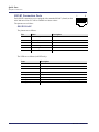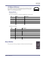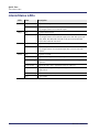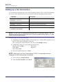
1
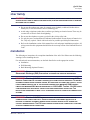
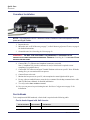
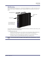
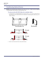
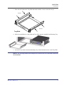
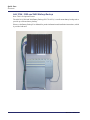
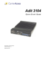
Adit 3104 QUICK START GUIDE Part Number: 002-0219-0410 Product Release: 1.6 September 2007 Copyright 2007 Carrier Access Corporation. All rights reserved. The information presented in this manual is subject to change without notice and does not represent a commitment on the part of Carrier Access Corporation. The hardware and software described herein are furnished under a license or nondisclosure agreement. The hardware, software, and manual may be used or copied only in accordance with the terms of this agreement. It is against the law to reproduce, transmit, transcribe, store in a retrieval system, or translate into any medium - electronic, mechanical, magnetic, optical, chemical, manual, or otherwise - any part of this manual or software supplied with the Adit 3104 for any purpose other than the purchaser’s personal use without the express written permission of Carrier Access Corporation. The Carrier Access Logo and Adit are registered trademarks of Carrier Access Corporation. All other brand or product names are trademarks or registration trademarks of their respective companies or organizations. Contact Information: Carrier Access Corporation 5395 Pearl Parkway Boulder, CO 80301-2490 Corporate Phone: (303) 442-5455 Fax: (303) 443-5908 www.carrieraccess.com Customer Support Direct: (800) 786-9929 E-mail: [email protected] QUICK START GUIDE Quick Start In this Guide Unpacking and Inspection Installation Environment User Safety Installation Compliant Installation Ferrite Beads Wall Mounting Rack Mounting (Optional Feature) Adit 3104, 3200 and 3400 Battery Backup Chassis Overview Interface Connectors Reset Button Alarm/Status LEDs Web-Based Management Setting up a CLI Connection Log in Key Enabled Software Features Basic Configuration - Setup Adit for access via Web-Browser Restore Factory Defaults Modify Default Admin User Configure Ethernet WAN Interface Configure Serial1 as WAN Configure the Adit 3104 as a SIP Line Gateway Quick Start Unpacking and Inspection Unpacking and Inspection WARNING! OBSERVE PRECAUTIONS FOR HANDLING ELECTROSTATIC DEVICES. 1. Inspect containers for damage during shipment. Report any damage to the freight carrier for possible insurance claims. 2. Compare packing list with office records. Report any discrepancies to the office. 3. Open shipping containers, be careful not to damage contents. 4. Inspect contents and report any damage. 5. If equipment must be returned for any reason, carefully repack equipment in the original shipping container with original packing materials if possible. 6. If equipment is to be installed later, replace equipment in original shipping container and store in a safe place until ready to install. Electrostatic Discharge (ESD) Precautions ESD can damage processors, circuit cards, and other electronic components. Always observe the following precautions before installing a system component. 1. Do not remove a component from its protective packaging until ready to install it. 2. Wear a wrist grounding strap and attach it to a metal part of the system unit before handling components. If a wrist strap is not available, maintain contact with the system unit throughout any procedure requiring ESD protection. WARNING! INTEGRATED CIRCUITS (ICS) ARE EXTREMELY SUSCEPTIBLE TO ELECTROSTATIC DISCHARGE. UNLESS YOU ARE A QUALIFIED SERVICE TECHNICIAN WHO USES TOOLS AND TECHNIQUES THAT CONFORM TO ACCEPTED INDUSTRY PRACTICES, DO NOT HANDLE ICS. The ESD warning label appears on packages and storage bags that contain static-sensitive products and components. Installation Environment The environment in which you are installing the Adit 3000 must meet the following conditions: z Operating temperature range: 32° to 104° F (0° to 40° C) z Storage temperature range: -40° to 158° F (-40° to 70° C) z Maximum operating altitude: 10,000 ft. (3,048 m) z Maximum non-operating altitude: 40,000 ft. (12,192 m) z Relative humidity (non-condensing) range: 0 to 95% WARNING! THE ADIT 3000 IS DESIGNED FOR WALL AND RACK MOUNTING ONLY. IT IS NOT DESIGNED FOR DESKTOP USE. 4 Adit 3104 - Release 1.6 Quick Start User Safety User Safety CAUTION! WHEN USING YOUR TELEPHONE EQUIPMENT, BASIC SAFETY PRECAUTIONS SHOULD ALWAYS BE FOLLOWED TO REDUCE THE RISK OF FIRE, ELECTRIC SHOCK AND INJURY TO PERSONS, INCLUDING THE FOLLOWING: z Do not use this product near water for example, near a bathtub, washbowl, kitchen sink or laundry tub, in a wet basement or near a swimming pool. z Avoid using a telephone (other than a cordless type) during an electrical storm. There may be a remote risk of electric shock from lightning. z Do not use the telephone to report a gas leak in the vicinity of the leak. z Use only the power cord and batteries indicated in this manual. Do not dispose of batteries in a fire. They may explode. Check with local codes for possible special disposal instructions. z Refer to the installation section of this manual for a safe and proper installation procedure. All wiring external to this equipment should follow the current provision of the National Electrical Code. Installation The following are instructions for a compliant installation of the Adit 3104. Please note the following warnings, before installing the unit. For wall and rack mount instructions, use the links listed below to the appropriate section: z Installation z Wall Mounting z Rack Mounting (Optional Feature) WARNING! OBSERVE PRECAUTIONS FOR HANDLING ELECTROSTATIC DEVICES. SEE Electrostatic Discharge (ESD) Precautions ON PAGE 4 FOR DETAILED INFORMATION. WARNING! THE ADIT 3104 DS1 NETWORK INTERFACE PORTS ARE CERTIFIED WITH ACTA, INDUSTRY CANADA AND UL FOR DIRECT CONNECTION TO PUBLIC DIGITAL NETWORKS. TO PREVENT EQUIPMENT DAMAGE FROM LIGHTNING SURGES, AC INDUCTION OR POWER LINE CONTACT, UTILIZE LISTED PRIMARY PROTECTORS AT THE BUILDING ENTRANCE WITH MINIMUM 4 OHM CURRENTLIMITING AND MAXIMUM 600V IMPULSE BREAKDOWN AT 1000V/USEC. THE ADIT 3104 DS1 PORTS COME EQUIPPED WITH SECONDARY OVERVOLTAGE AND OVERCURRENT PROTECTION. THE INSTALLATION IS REQUIRED TO MEET LOCAL OR NATIONAL ELECTRIC CODES FOR COMMUNICATION SYSTEMS. WARNING! THE ADIT 3104 FXS INTERFACE PORTS ARE INTENDED TO SERVE INDOOR COMMUNICATION CONDUCTORS ONLY. OVERVOLTAGE AND OVERCURRENT PROTECTION IS PROVIDED TO PREVENT EQUIPMENT DAMAGE FROM LIGHTNING SURGES OR AC POWER LINE CONTACT INSIDE BUILDINGS. THE FXS PORTS ARE NOT SUITABLE FOR CONNECTION TO EXPOSED OUTDOOR COMMUNICATION CONDUCTORS. Adit 3104 - Release 1.6 5 Quick Start Installation Compliant Installation NOTE: It is important the DS1/E1 Network Interface Cables are secured separately from the power and Signal Cables. 1. Inspect the unit. 2. Mount the unit, see Wall Mounting on page 7, or Rack Mounting (Optional Feature) on page 8 for detailed instructions. 3. Ground the unit. See Grounding the Unit on page 12. WARNING! THE ADIT 3104 IS REQUIRED TO BE PERMANENTLY GROUNDED FOR THE PROTECTION OF USERS AND SERVICE PERSONNEL. DETAILED INSTRUCTIONS. REFER TO Grounding the Unit ON PAGE 12 FOR 4. Connect DS1 (T1), Ethernet and Amphenol connectors as needed. Note: if Amphenol (25-pin telco) connector is used, a ferrite bead is required to meet compliance (see graphic above). 5. Connect RS-232 connector and open Terminal Emulator software on your PC. Note: With this running first, you can monitor the boot process. 6. Connect Power to the unit. 7. Monitor the boot process on your PC, when complete the status light should be green. 8. For any software enabled features, enter the key command. See the key command in the Adit 3000 CLI Reference Manual, for detailed information. 9. To verify use the show version command. 10. Now you can proceed to provisioning the unit. See Basic Configuration on page 23 for information. Ferrite Beads To be compliant with EMI standards, a ferrite bead is required on the following cable: Ferrite bead shipped with Adit chassis: 6 Ferrite Provided Part Number Intended For 1 large P/N 010-0051 25-pair Telco cable (connector on the front of the Adit). Adit 3104 - Release 1.6 Quick Start Installation Wall Mounting Before beginning the mounting process, verify that the installation area is a stable environment, clean and free from extremes of temperature, shock, vibration and EMI. See Installation Environment on page 4. Mounting Bracket Back of unit Front of unit Leave adequate space at the front/back for access to connectors The Adit 3000 is delivered with mounting brackets that can easily be attached for quick and easy wall mounting, as shown in the illustration above. To install the unit to the wall: 1. Attach the wall mount brackets to the Adit 3000, with wall attachment flange pointing away from the unit, as shown above. Attach with 4 screws provided (2 for each bracket). 2. Mount the unit to the wall using appropriate mounting screws (not included). Note: it is acceptable to mount on drywall with suitable anchor-type mounting screws. NOTE: The Adit 3000 must be mounted with the brackets on the top and bottom, as shown above. Adit 3104 - Release 1.6 7 Quick Start Installation Rack Mounting (Optional Feature) NOTE: Rack mounting kits are available for both 19 and 23 inch racks. 1 Rack Unit (RU) of spacing is required above the Adit 3000 in the Rack Mount Unit. To rack mount the Adit 3000, follow the instructions below: 1. Attach bracket ears to Rack Mounting Tray using four #10-32 x 1/4" screws on each side. The Mounting Ears can be used for both a 19 or 23 inch rack. The drawing below shows a top view of the 2 versions. Mounting Ear Rack Mounting Tray Rack Mount Tray screws Mounting Ear screws Front Rack Mount Tray screws Mounting Ear 23 in rack Front Mounting Ear 19 in rack screws Mounting Ear 2. Remove wall mount and screws from Adit 3000 unit. 8 Adit 3104 - Release 1.6 Quick Start Installation 3. Place the Adit 3000 on the Tray Slide and attach with the 4 screws removed in step 2. screws screws Tray Slide 4. Slide the assembled piece (Adit 3000 and Tray Slide) onto the installed Rack Mounting Tray. 5. Secure the Tray Slide to the Rack Mounting Tray with the attached screws on the Tray Slide. NOTE: the mounting brackets are designed to not allow units to be mounted closer than recommended. Adit 3104 - Release 1.6 9 Quick Start Installation Adit 3104, 3200 and 3400 Battery Backup Note: This is an Optional Feature. The Adit 3104, 3200 and 3400 Battery Backup (P/N 730-0132), is a wall-mount battery backup unit to provide up to 8 hours battery backup. Please see the Battery Backup User Manual for product information and installation instructions, which is provided with unit. 10 Adit 3104 - Release 1.6 Quick Start Chassis Overview Chassis Overview Front Alarm Status (4) 10/100Base-T Ethernet (LAN) Reset (1) DS1/E1 (WAN) (E1-future) (1) 10/100Base-T Ethernet (WAN) Tip & Ring Telco Connector Back Ground Adit 3104 - Release 1.6 Power/Battery/Status RS-232 Management Port 11 Quick Start Interface Connectors Interface Connectors Front of Adit z (1) DS1 WAN port (RJ-48C). Note: E1 will be in a future release. z (1) 10/100Base-T WAN port (RJ-45) z (4) 10/100Base-T switched LAN ports (RJ-45) z Tip & Ring Analog Interface equipped with standard 25-pair Telco Connector Back of Adit z RS-232 craft port connector for local management z Power input connector z Ground connector Grounding the Unit WARNING! THE ADIT 3104 IS REQUIRED TO BE PERMANENTLY GROUNDED FOR THE PROTECTION OF USERS AND SERVICE PERSONNEL. Chassis ground is located on the back of the unit. To ground the unit: 1. Connect a minimum 14 AWG ground wire with a #8 ring tongue terminal (not included) to the chassis ground on the back of the unit. Secure with the 8-32 screw and lock washer provided. Chassis Ground 2. Connect the opposite end of the ground wire to a suitable earth grounding point such as a building grounding electrode, metal water pipe, or metal building structure that is in compliance with article 250 of NEC. 12 Adit 3104 - Release 1.6 Quick Start Interface Connectors Power The Adit 3000 is powered by a limited -48 VDC Power source. The following options are available: AC/DC Converter z Battery Backup module z AC/DC Converter An AC/DC Converter generates 48VDC from any worldwide AC power source. To connect AC power: 1. Plug power connector from AC/DC converter into rear of Adit 3000. 2. Connect AC/DC converter to wall outlet. 3. A green light should appear on the Status LED on the front of the unit. PIN 10, ORANGE PIN 5, BLACK CAUTION! INCORRECT WIRING OF CORD MAY CAUSE EXTERNAL FUSE FAILURE. WARNING! POSSIBLE SHOCK HAZARD EXISTS, PLEASE FOLLOW INSTRUCTIONS CAREFULLY. To connect -48 VDC power: 1. Wire appropriate connector to open end of the DC Power cable. Orange = -48 Black = Ground (+) 2. Plug the DC power connector in the -48 VDC input power connector. 3. Apply power to connector from -48 VDC power source. 4. A green light should appear on the Status LED on the front of the unit. WARNING! EXTERNAL FUSE PROTECTION IS REQUIRED ON THE 48VDC INPUT WHEN CONNECTED TO A DC POWER SOURCE NOT SUPPLIED BY CARRIER ACCESS. Fuse Recommendations, or equivalent: Recommended Fuse Littelfuse 48101.5 Bussman GMC-1.5A AMP Rating 1.5 Amp 1.5 Amp Battery Connection The Adit 3000 Battery connection is provided for Battery Backup. See Adit 3104, 3200, 3300 and 3400 Battery Backup on page 8 for additional information. Adit 3104 - Release 1.6 13 Quick Start Interface Connectors 25-Pair Telco Connector Tip and Ring Analog Interfaces equipped with standard 25-pair Telco Connectors (female) for connection to key systems, fax machines, modems, and PBXs. Circuit connections are made at the 25-pair telco connectors. A standard 25-pair telephone cable with RJ21X wiring and a male D-type connector at the Adit 3000 end is required. The pinouts are as follows: 14 Pair Pin Function Color Code 1 26 1 Tip Channel 1 Ring Channel 1 2 27 2 3 26 50 1 25 Pair Pin Function Color Code White/Blue Blue/White 14 39 14 Tip Channel 14 Black/Brown Ring Channel 14 Brown/Black Tip Channel 2 Ring Channel 2 White/Orange Orange/White 15 40 15 Tip Channel 15 Black/Slate Ring Channel 15 Slate/Black 28 3 Tip Channel 3 Ring Channel 3 White/Green Green/White 16 41 16 Tip Channel 16 Yellow/Blue Ring Channel 16 Blue/Yellow 4 29 4 Tip Channel 4 Ring Channel 4 White/Brown Brown/White 17 42 17 Tip Channel 17 Yellow/Orange Ring Channel 17 Orange/Yellow 5 30 5 Tip Channel 5 Ring Channel 5 White/Slate Slate/White 18 43 18 Tip Channel 18 Yellow/Green Ring Channel 18 Green/Yellow 6 31 6 Tip Channel 6 Ring Channel 6 Red/Blue Blue/Red 19 44 19 Tip Channel 19 Yellow/Brown Ring Channel 19 Brown/Yellow 7 32 7 Tip Channel 7 Ring Channel 7 Red/Orange Orange/Red 20 45 20 Tip Channel 20 Yellow/Slate Ring Channel 20 Slate/Yellow 8 33 8 Tip Channel 8 Ring Channel 8 Red/Green Green/Red 21 46 21 Tip Channel 21 Violet/Blue Ring Channel 21 Blue/Violet 9 34 9 Tip Channel 9 Ring Channel 9 Red/Brown Brown/Red 22 47 22 Tip Channel 22 Violet/Orange Ring Channel 22 Orange/Violet 10 35 10 Tip Channel 10 Red/Slate Ring Channel 10 Slate/Red 23 48 23 Tip Channel 23 Violet/Green Ring Channel 23 Green/Violet 11 36 11 Tip Channel 11 Black/Blue Ring Channel 11 Blue/Black 24 49 24 Tip Channel 24 Violet/Brown Ring Channel 24 Brown/Violet 12 37 12 Tip Channel 12 Black/Orange Ring Channel 12 Orange/Black 25 50 25 Reserved 13 38 13 Tip Channel 13 Black/Green Ring Channel 13 Green/Black Violet/Slate Slate/Violet Adit 3104 - Release 1.6 Quick Start Interface Connectors RS-232 Craft Port (Female DB-9) The RS-232 craft port connector (female) is for connection to an external PC or Hayes-compatible modem for local or remote configuration, management, and performance monitoring using the Adit 3000 Command Line Interface (CLI). The RS-232 craft port connects via a female DB-9 connector on the Adit 3000. 1 5 6 9 The pinouts are as follows: Pin Number Direction Description 1 Outbound Carrier Detect 2 Outbound Receive Data 3 Inbound Transmit Data 4 Inbound Data Terminal Ready 5 N/A Signal Ground 6 Outbound Data Set Ready 7 Inbound Request to Send 8 Outbound Clear to Send 9 N/C Not connected Adit 3104 - Release 1.6 15 Quick Start Interface Connectors DS1/E1 Connection Ports 1 8 Each DS1/E1 connection port is equipped with a standard RJ-48C (female) on the Adit 3000 unit. Note: E1 will be available in a future release. The pinouts are as follows: DS1/E1 RJ-48C The pinouts are as follows: Pin Name Description 1 Receive Ring Receive from DS1 network 2 Receive Tip Receive from DS1 network 3 N/C Not connected 4 Transmit Ring To DS1 network 5 Transmit Tip To DS1 network 6-8 N/C Not connected The LEDs are as follows (left LED only): 16 State Description Off Off line Green Normal Red Loss of Signal (LOS) Yellow Bipolar Violation (BPV) Flashing Green Loopback active Flashing Yellow Yellow Alarm (Remote Alarm Indication) Flashing Red (Slow) Loss of Frame (LOF) or Alarm Indication Signal (AIS) Flashing Red (Fast) Self-test Failure Adit 3104 - Release 1.6 Quick Start Reset Button 10/100Base-TX Ethernet The 10/100Base-TX Ethernet (female) ports provide connectivity for Router WAN and/or LAN ports and for management connection via Telnet and/or SNMP to a Network Management System. 1 8 8 Ethernet (RJ-45) 1 The pinouts are as follows: Note: This is a hub pinout, you will need a straight cable to connect to a PC. Pin Name Description 1 Receive + Receive from network 2 Receive - Receive from network 3 Transmit + Transmit to network 4-5 N/C Not connected 6 Transmit - Transmit to network 7-8 N/C Not connected The LEDs are as follows: LED State Left LED The left LED shall show Link Status. Right LED Description Off Link Down Green Link Up Flashing Green Traffic on Link Yellow Collision status The right LED shall indicate Link Speed. Off 10 Mbit/sec, down or not connected Green 100 Mbit/sec Reset Button The system can be reset by pressing the reset button located on the front panel. Adit 3104 - Release 1.6 17 Quick Start Alarm/Status LEDs Alarm/Status LEDs LED State Description Critical Off No critical alarms present Red Critical alarms present. Critical alarms include: user-configured manor environmental inputs. Off No major alarms present Red Major alarm present. Major alarms include: user-configured manor environmental inputs, DS1 short, DS1 open, DS1 facility alarm, DS1 RAI, DS1 AIS, DS1 LOF, DS1 LOS, WAN fault, Ethernet fault and dead card alarms. Off No minor alarms present Red Minor alarms present. Minor alarms include: user-configured minor environmental inputs, DS1 excessive line code violations. Off No power to system Green Application running, no detected system problems. Green Flashing Power-On Self Test (POST) successful. System booted. Loading Application. Green/Yellow Flashing alternate colors. Application Self Test in Process. Yellow Yellow while booting. If this stays a steady yellow the Power-On Self Test (POST) failed. Yellow Flashing Power-On Self Test (POST) In Process. Red System Failure Major Minor Status 18 Adit 3104 - Release 1.6 Quick Start Web-Based Management Web-Based Management The web-based management interface allows you to control various system parameters. The interface is accessed through a web browser. To access the management console: NOTE: The following assumes that you have connected the PC to the LAN port of the Adit 3104. 1. Launch a web browser on your PC in the LAN to which the Adit 3104’s LAN port is connected. Note: If connection to the 3104 is to be through an Ethernet or T1 WAN, the remote admin WAN access must be enabled with the following command sequence: Command Username: admin Description Log into the system (username and password). Password: ******** Adit 3104> enable Enter the Privileged mode. Password: ******** Enter password for the Privileged mode. #configure terminal Enter the Configuration mode. (config)# remote-admin web primary-port enable Enable remote web admin. 2. Type the Adit 3104’s IP address or name in the address bar. Example: http://192.168.1.1. z Default IP address is http://192.168.1.1 Note: to display the current IP address of the systems, use the following CLI command: #show interface ethernet 1 (LAN) #show interface ethernet 2 (Eth WAN) 3. Login to the unit. Enter User Name and Password. Note: these setting should be changed from the default settings after the initial login. z Default user name is admin z Default password is admin 123 NOTE: After a few minutes of inactivity, the session will automatically timeout and the operator will be required to log in to continue the session. WARNING! IF YOUR USER NAME AND PASSWORD ARE SET TO THE DEFAULT SETTING, IT IS RECOMMENDED THAT YOU MODIFY THEM FOR SECURITY PURPOSES. Adit 3104 - Release 1.6 19 Quick Start Setting up a CLI Connection Setting up a CLI Connection A CLI connection will require the LAN or WAN IP address of the unit. Note: If the WAN IP address is used, the remote admin WAN access must be enabled with the following command sequence: Command Username: admin Description Log into the system (username and password). Password: ******** Adit 3104> enable Enter the Privileged mode. Password: ******** Enter password for the Privileged mode. #configure terminal Enter the Configuration mode. (config)# remote-admin web primary-port enable Enable remote web admin. NOTE: For Adit 3104 CLI commands see the Adit 3000 CLI Reference Manual. This is a separate document and can be found on the CD that is provided with the product, or on the Carrier Access customer website. To connect with CLI, set up the connection: z If connecting via the Ethernet 100Base-TX connection, use a Telnet TCP/IP program to access the CLI. This requires an IP address of the unit. Note: to display the current IP address of the unit, use the ifconfig command. z If connecting via RS-232, the port settings should be set to: Bits per second: 115200 Data bits: 8 Parity: None Stop bits: 1 Flow control: None z Set your Terminal Emulation to: VT100 NOTE: When using Tera Term (Telnet program) TCP/IP, CLI commands will not be recognized until the following setup is completed. 20 z In Tera Term go to Setup/Terminal z Set the New-line/Transmit value CR+LF Adit 3104 - Release 1.6 Quick Start Log in Log in After successful connection, via telnet or HyperTerm, the user must login. Default Logins are: Login: admin Password: admin123 After successful login the prompt will be displayed as follows: Adit 3104> NOTE: It is recommended that you change your password from the default. Adit 3104 - Release 1.6 21 Quick Start Key Enabled Software Features Key Enabled Software Features The Adit 3104 has additional features that are not provided on the base system. These features can be purchased with the product or added later as needed. These features are enabled via a Software Key (example: G.729). The number of keyed features may expand with the development of the product, therefore to see a list of current keyed features, or to purchase a key, contact Carrier Access Customer Service or Sales. To enter a software key, use the following CLI command: Syntax: (config)# key {key-code} Example: (config)# key cxusdfutkj3diosn412C NOTE: Keys may only be entered through the CLI (not through the GUI). The Key Enabled Software Features are displayed on the Advanced/Technical Information window. This information is also displayed with the following CLI command: Adit 3104> show version Application Version: 1.5.0.24 Compilation Time: Thu Jun 14 2007 18:43:10 FPGA Version: 2.00 Board Version: 0 003-1129-0020 IXP400 Software Release: 1_4 SQA4_1 Voice Slot 1 : FXS Card Present: Rev 1.00 Voice Slot 2 : -- EMPTY -Voice Slot 3 : -- EMPTY -Vendor: Carrier Access CLEI Code: IPMP200JRA Product Features: VPN enabled. MGCP enabled. SIP enabled. 22 CLEI Code:IPU3AARBAA Adit 3104 - Release 1.6 Quick Start Basic Configuration Basic Configuration The following configuration is divided into logical sections, where each section configures an additional function. The first must be configured before the second and so forth, however, you may stop at any section and not add the following feature. NOTE: The order in which commands are entered can affect the successful provisioning of the Adit 3104. z z z z z z Setup Adit for access via Web-Browser Restore Factory Defaults Modify Default Admin User Configure Ethernet WAN Interface Configure Serial1 as WAN Configure the Adit 3104 as a SIP Line Gateway Setup Adit for access via Web-Browser The following steps will configure the Adit 3104 to allow access to the Web Browser for configuration, through one of the 4 10/100Base-T LAN connections. Note: for LAN access, no additional configuration is required to access the Adit using the web browser. To configure the WAN access: 1. Connect to the CLI via the DB-9 RS-232. See Setting up a CLI Connection on page 20. 2. Enable the remote admin WAN access with the following command sequence: Command Username: admin Description Log into the system (username and password). Password: ******** Adit 3104> enable Enter the Privileged mode. Password: ******** Enter password for the Privileged mode. #configure terminal Enter the Configuration mode. (config)# remote-admin web primary-port enable Enable remote web admin. Adit 3104 - Release 1.6 23 Quick Start Basic Configuration Restore Factory Defaults If the unit is not out-of-the-box, you may want to verify that the unit is set to defaults. Note: this will reset the IP address back to the default setting of 192.168.1.1. In the web-browser: 24 z Select Advanced from the Navigation bar z Select Restore Defaults z Select OK to restore defaults Adit 3104 - Release 1.6 Quick Start Basic Configuration Modify Default Admin User For security purposes it is recommended that the Administrator User be changed from the default settings. Modify the Administrator User in the web-browser: z Select Advanced from the Navigation bar z Select Users icon z Select Administrator, to open the profile. Adit 3104 - Release 1.6 25 Quick Start Basic Configuration z 26 Modify the User information, and select OK to save. It is important to note that you need to have a minimum of one user with Administrative Privileges. For users with other access levels, add a New User. Note: For security purposes, the password should be changed. Adit 3104 - Release 1.6 Quick Start Basic Configuration Configure Ethernet WAN Interface In the web-browser: 1. Select Network Connections from the Navigation bar. 2. It is recommended that you disable/delete the Serial1 port. 3. Select (click) Ethernet 2 (WAN Ethernet) connection to configure. 4. Select the Enable button, to configure the WAN Ethernet up (or in-service). 5. Select the Settings button. Adit 3104 - Release 1.6 27 Quick Start Basic Configuration 6. Set Internet Protocol to Obtain an IP Address Automatically, from the pulldown menu. This will enable the Adit 3104 as a DHCP Client. Leave the other fields to their default settings. 7. Select Apply to apply the new settings. 28 Adit 3104 - Release 1.6 Quick Start Basic Configuration Configure Serial1 as WAN In the web-browser: 1. Select Network Connections from the Navigation bar. 2. Select Serial1. 3. Select Settings button. 4. Set Network to WAN. 5. Select Apply to apply the new settings. Adit 3104 - Release 1.6 29 Quick Start Basic Configuration 6. Select the Enable button. 30 Adit 3104 - Release 1.6 Quick Start Basic Configuration Configure the Adit 3104 as a SIP Line Gateway In the web-browser: 1. Select Voice Over IP from the Navigation bar. 2. Select Use SIP Proxy. 3. Enter Softswitch IP Address, User name and Password. 4. Select applicable Codecs. 5. Select Apply to apply the new settings. Adit 3104 - Release 1.6 31 Quick Start Basic Configuration 6. Select the Phone Settings tab. 7. Select the Action icon on line #1 to edit. 32 Adit 3104 - Release 1.6 Quick Start Basic Configuration 8. Enter a telephone number in the User ID field and select OK. 9. Repeat this step for each line you would like to have register with your Softswitch. Adit 3104 - Release 1.6 33 Quick Start Basic Configuration 34 Adit 3104 - Release 1.6