1
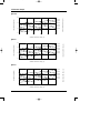
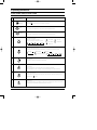
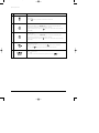
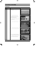
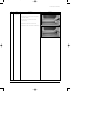
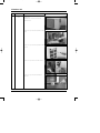
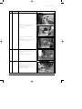
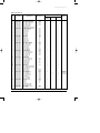
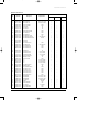
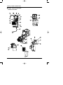
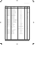
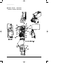
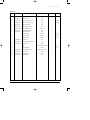
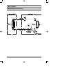
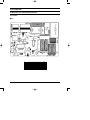
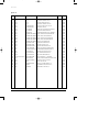
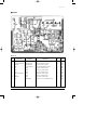
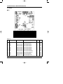
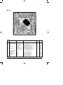
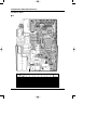
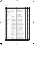
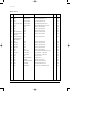
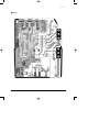
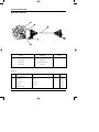
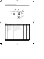
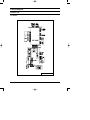
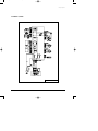
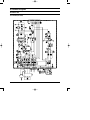
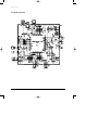
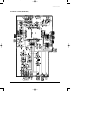
AQ12PGGE_co
3/4/03 10:22 AM
Page 3
ROOM AIR CONDITIONER
INDOOR UNIT
AQ12PGGE
SH12ZPG
SH12ZPGA
SH09ZPG
SH09ZPGA
SH07ZPG
SH07ZPGA
SERVICE
AIR CONDITIONER
OUTDOOR UNIT
UQ12PGGE
SH12ZPGX
SH12ZPGAX
SH09ZPGX
SH09ZPGAX
SH07ZPGX
SH07ZPGAX
Manual
CONTENTS
1. Product Specifications
2. Operating Instructions
3. Disassembly and Reassembly
4. Exploded Views and Parts List
5. Block Diagrams
6. PCB Diagrams
7. Wiring Diagrams
8. Schematic Diagrams
AQ12PGGE_1
3/4/03 10:51 AM
Page 2-1
1. Product Specifications
1-1 Table
AQ12PGGE
SH12ZPG
SH12ZPGA
Model
Item
Indoor unit
Outdoor unit
Indoor unit
Outdoor unit
Wall-mounting
Wall-mounting
3.5
2.6
2.3
Heating
kW
3.8
2.9
2.4
Dehumidifying
|/h
Cooling
Air volume
m3/min
Heating
Cooling
Noise
dB
Heating
Energy efficiency ratio
Cooling
1.9
Heating
Operating Current
Cooling
6.6
24
6.0
24
9.1
24
7.1
24
6.5
24
42
50
39
49
36
48
42
50
39
49
36
48
3.21
Cooling
Cooling
Power factor
Starting current
Length
Power cord
3.29
3.43
1-220 / 240-50
1-220 / 240-50
1090
810
715
1115
870
700
5.0
3.7
3.2
5.0
3.9
3.2
94.8
95.2
97.1
97.0
97.0
95.1
A
32.0
21.0
18.0
m
-
-
-
-
-
-
%
Heating
Number of core wire
Capacity
3.22
3.41
A
Heating
2.93
1-220 / 240-50
W
Heating
0.9
24
V-Hz
Power Consumption
1.4
8.2
W/W
Power
250V-10 / 16A
A
250V-10 / 16A
Outer
Width x Height
mm
Dimension
x Depth
inch
35.0x11.2x7.0 27.4x20.9x11.0 31.3x10.2x7.0 27.4x20.9x11.0
kg
Refrigerant pipe
8.5
28.0
695x530x280
31.3x10.2x7.0 27.4x20.9x11.0
7.5
27.5
mm x L(MT)
mm x L(MT)
ø12.7 x 5
ø9.52 x 5
ø9.52 x 5
D x L(mm)
ø18 x 2000
ø18 x 2000
ø18 x 2000
Rotary
Rotary
Rotary
-
Type
Type
Motor
7.5
795x258x179
Liquid
Rated output
Blower
695x530x280
GAS
Type
Motor
33.0
795x258x179
ø6.35 x 5
Drain hose
Compressor
695x530x280
250V-10 / 16A
890x285x179
Weight
Size
Indoor unit
Wall-mounting
Cooling
Power
Outdoor unit
SH07ZPG
SH07ZPGA
kW
Type
Performance
SH09ZPG
SH09ZPGA
Type
Rated output
W
-
ø6.35 x 5
ø6.35 x 5
-
-
-
-
-
-
-
-
-
-
Cross-flow
Propeller
Cross-flow
Propeller
Cross-flow
Propeller
steel
steel
steel
steel
steel
steel
15
25
11
25
11
25
2ROW 12STEP 2ROW 24STEP 2ROW 10STEP 1ROW 20STEP 2ROW 10STEP 1ROW 20STEP
Heat exchanger
CAPILLARY TUBE
CAPILLARY TUBE
CAPILLARY TUBE
cc
410
360
360
g
980
740
700
Protection device
RAC 12123-9622
RAC 12054-9612
RAC 12144-9622
Cooling test Condition
INDOOR UNIT : DB27˚C WB19˚C
OUTDOOR UNIT : DB35˚C WB24˚C
Maximum operation Condition
INDOOR UNIT : DB32˚C WB23˚C
OUTDOOR UNIT : DB43˚C WB26˚C
Refrigerant control unit
Freezer oil capacity
Refrigerant to change(R-22)
Samsung Electronics
1-1
3/4/03 10:25 AM
Page 2-2
1-2 Pressure Graph
■
12K BTU
Low pressure (kg/cm2G)
32.4/24.0
30.6/22.5
5.5
28.8/21.0
27.0/19.0
24.0/17.0
21.5/15.0
4.5
Indoor inlet air D.B. temp (˚C)
6.5
3.5
20
25
30
35
40
45
Outdoor inlet air D.B. temp (˚C)
■
9K BTU
Low pressure (kg/cm2G)
32.4/24.0
30.6/22.5
5.5
28.8/21.0
27.0/19.0
24.0/17.0
4.5
21.5/15.0
Indoor inlet air D.B. temp (˚C)
6.5
3.5
20
25
30
35
40
45
Outdoor inlet air D.B. temp (˚C)
■
7K BTU
32.4/24.0
30.6/22.5
6
28.8/21.0
27.0/19.0
24.0/17.0
5
4
21.5/15.0
20
25
30
35
40
Indoor inlet air D.B. temp (˚C)
7
Low pressure (kg/cm2G)
AQ12PGGE_1
45
Outdoor inlet air D.B. temp (˚C)
1-2
Samsung Electronics
AQ12PGGE_1
3/4/03 10:25 AM
Page 2-3
2. Operating Instructions
2-1 The Feature of Key in remote control
NO
1
FUNCTION OF KEY
NAMED OF KEY
(On/Off)
On/Off button.
Press the
button to stop or run the air conditioner.
(UP)
Temperature adjustment button(UP).
To increase the temperature by the pressing the temperature button.
(DOWN)
Temperature adjustment button(DOWN).
To decrease the temperature by the pressing the temperature button.
2
3
Mode selection button.
Each time you press this button
Mode is changed in the following order
: Auto Mode
: Fan Only
: Cool Mode
: Heat Mode
: Dry Mode
Fan speed adjustment button.
Each time you press this button, FAN SPEED is changed in the following order.
4
Low
Medium
High
Automatic(ratated :
)
5
Swing button.
It adjusts the airflow to upward and downward.
6
Turbo button.
The air conditioner cools or heats the room as quickly as possible.
After 30minutes, the air conditioner is reset automatically to the previous mode.
7
Energy saving button.
If you wish to save energy when using your air conditioner, select the Energy saving
mode with the
button.
8
Sleep button.
The sleep timer can be used when you are cooling or heating your room to switch the
air conditioner off automatically after a period of six hours.
Samsung Electronics
2-1
AQ12PGGE_1
3/4/03 10:25 AM
Page 2-4
Operating Instructions
NO
NAMED OF KEY
FUNCTION OF KEY
9
Anion button.
Press the button to generate ion from the air conditioner.
10
On Timer button.
The On Timer enables you to switch on the air conditioner automatically after
a given period of time that is from 30 minutes to 24 hours.
To set the operating time, press the
button one or more times until the required
time display.
11
Off Timer button.
The Off Timer enables you to switch off the air conditioner automatically after
a given period of time that is from 30 minutes to 24 hours.
To set the operating time, press the
button one or more times until the required
time display.
12
Timer Set/Cancel button.
After setting On Timer or Off Timer, press the
button to set it completely.
And press the
button again to cancel On Timer or Off Timer set.
13
Digital On/Off button.
If you want to turn off the display during operation press the
2-2
button.
Samsung Electronics
AQ12PGGE_1
3/4/03 10:25 AM
Page 2-5
Operating Instructions
2-1-1 Name & Function of Key in remote control
1. AUTO MODE : In this mode, operation
mode(COOL, HEAT) is selected automatically by the room temperature of initial
operation.
Room Temp
Operation Type
Tr≥ 21°C+∆T
Cool Operation (Set Temp:24˚C+∆T)
21°C +∆T>Tr
Heat Operation (Set Temp:22˚C+∆T)
∆T= -1°C, -2°C, 0°C+1°C+2°C
∆T is controlled by setting temperature
up/down key of remote control
2. COOL MODE : The unit operates according to the difference between the setting
and room temperature. (18°C~30°C)
3. HEAT MODE : The unit operates according to the difference between the setting
and room temperature.(16°C~30°C)
*Prevention against cold wind : In order to
prevent the cool air from flowing out at
the heat mode, the indoor fan does not
operate or operates very slowly in the
following cases. At this time, the indoor
heat exchanger will be preheating.
- For 3~5 minutes after the initial
operation
- For deicing operation
- The operation of an indoor fan in
accordance with the temperature of an
indoor heat exchanger
The temperature of
indoor heat exchanger
Indoor fan speed
below 28˚C
28˚C~below 34˚C
34˚C~below 40˚C
above 40˚C
off
LL Speed
L Speed
Setting Speed
*High temperature release function : It is a
function to detect an outdoor overload by
the sensor of an indoor heat exchanger
and to turn the outdoor fan or the
compressor ON/OFF for safety.
Samsung Electronics
*Deice : Deicing operation is controlled
by indoor unit's heat exchanger temperature and accumulating time of compressor's operation.
Deice ends by sensing of the processing
time by deice condition.
4. DRY MODE : Has 3 states, each determined by room temperature.
The unit operates in DRY mode.
*Compressor ON/OFF Time is controlled
compulsorily(can not set up the fan
speed, always breeze).
*Protective function : Low temperature
release. (Prevention against freeze)
5. TURBO MODE : This mode is available in
AUTO, COOL, HEAT, DRY, FAN MODE.
When this button is pressed at first, the
air conditioner is operated “powerful”
state for 30 minutes regardless of the set
temperature, room temperature.
When this button is pressed again, or
when the operating time is 30 minutes,
turbo operation mode is canceled and
returned to the previous mode.
*But, if you press the TURBO button in
DRY or FAN mode that is changed with
AUTO mode automatically.
6. SLEEP MODE : Sleep mode is available
only in COOL or HEAT mode.
The operation will stop after 6 hours.
*In COOL mode : The setting temperature
is automatically raised by 1°C each 1hour
When the temperature has been raised by
total of 2°C, that temperature is maintained.
*In HEAT mode : The setting temperature
is automatically dropped by 1°C each
1hour.
When the temperature has been dropped
by total of 2°C, that temperature is maintained.
2-3
AQ12PGGE_1
3/4/03 10:25 AM
Page 2-6
Operating Instructions
7. FAN SPEED : Manual (3 step), Auto (4
step)
Fan speed automatically varies depending
on both the difference between setting and
the room temperature.
8. COMPULSORY OPERATION :
For operating the air conditioner without
the remote control.
*The air conditioner starts up in the most
suitable mode for the room temperature:
Room Temperature
Less than 21˚C
21˚C or above
Operating Mode
Heat
Cool
Temperature Setting
22˚C approx.
24˚C approx.
9. SWING : BLADE-H is rotated vertically by
the stepping motor.
*Swing Set : Press the
button under the
remote control is displayed on LCD the
and the blades move up and down. If
the one more time press the button,
blades location is stop.
10. SETTING THE ON/OFF TIMER. :
*ON TIMER : The On Timer enables you
to switch on the air conditioner automatically after a given period of time. You can
set the period of time from 30 minutes to
24 hours.
*OFF TIMER : The Off Timer enables you
to switch off the air conditioner automatically after a given period of time. You can
set the period of time from 30 minutes to
24 hours.
12. SELF DIAGNOSIS
Error Mode
DISPLAY 7-SEGMENT
Operation Off Operation On
Indoor unit room temperature sensor
error (open or short)
OFF
E1
Indoor unit heat exchanger temperature
sensor error(open or short)
OFF
E2
Indoor FAN MOTOR error :
Keep the RPM value 450 below for 15
seconds
OFF
E3
Communication error (PLC applied)
OFF
E4
EEPROM error
OFF
E6
All lamp
blinking
All lamp
blinking
Error in option
In case of No option set-up
In case of option data error
Remark
13. BUZZER SOUND : Whenever the
ON/OFF button is pressed or whenever
change occurs to the condition which is set
up or select, the compulsory operation
mode, buzzer is sounded "beep".
11. GENERATING ANION :
The air conditioner can generate anion
with an ionizer in the indoor unit.
2-4
Samsung Electronics
AQ12PGGE_1
3/4/03 10:25 AM
Page 2-7
3. Disassembly and Reassembly
Stop operation of the air conditioner and remove the power cord before repairing the unit.
3-1 Indoor Unit
No
Parts
Procedure
1
Front Panel
1) Stop the air conditioner operation and block
the main power.
2) Separate tape of front panel upper.
Remark
3) Slide the lower front grille down, then
disassemble it by pulling it forwards.
4) Open the upper front grille by pulling right
and left sides of the grille.
5) Take the left and right filter out.
6) Loosen one of the right screw and separate
the terminal cover.
7) Separate the thermistor from the front grille.
8) Loosen five fixing screws of front grille.
9) Pull the lower left and right of discharge
softly for the outside cover to be pulled out.
10) In order to disassemble the panel grille,
press, in order, the left, center, and right of
the upper side of the panel grille with the
palm of the hand to remove the hook.
And then disassemble the panel grille.
Samsung Electronics
3-1
AQ12PGGE_1
3/4/03 10:25 AM
Page 2-8
Disassembly and Reassembly
No
Parts
2
Electrical Parts
(Main PCB)
Procedure
Remark
1) Do “1”, above.
2) Take all the connector of PCB upper side out.
(Including Power cord)
3) Separate the outdoor unit connection wire
from the terminal block.
4) If pulling the Main PCB up. it will be taken
out.
3
Ass’y Tray Drain. 1) Do “1”, “2”, above.
Separate the drain hose from the extension
drain hose.
2) Pull tray drain out from the back body.
4
Heat Exchanger
1) Do “1”, “2”, “3”, above.
2) Loosen two fixing earth screws of right side.
3) Separate the connection pipe.
4) Separate the holder pipe at the rear side.
5) Loosen the three fixing screws of right and
left side.
6) Separate the heat exchanger from the
indoor unit.
3-2
Samsung Electronics
AQ12PGGE_1
3/4/03 10:25 AM
Page 2-9
Disassembly and Reassembly
No
Parts
5
Fan Motor and
Cross Fan
Procedure
Remark
1) Do “1”, “2”, ”3”, “4”, above.
2) Loosen the fixing two screws and separate
the motor holder.
3) Loosen the fixing screw of fan motor.
(M3 wrench)
4) Separate the fan motor from the fan.
5) Separate the fan from the left holder bearing.
Samsung Electronics
3-3
AQ12PGGE_1
3/4/03 10:25 AM
Page 2-10
3-2 Outdoor Unit
No
Parts
1
Common
Work
Procedure
Remark
1) Loosen 2 fixing screws and separate the
cover valve.
2) Separate the connection wire from the
terminal block.
3) Loosen 4 fixing screws and separate the cabi
front.
4) Loosen 2 fixing screws and separate the cabi
side LF.
5) Loosen 2 fixing screws of the cabi side RH.
6) Loosen 2 fixing screws and separate the
bar steel.
3-4
Samsung Electronics
AQ12PGGE_1
3/4/03 10:25 AM
Page 2-11
Disassembly and Reassembly
No
Parts
2
Fan and
Motor
Procedure
Remark
1) Do “1”, above.
2) Separate the connection wire of the motor
fan.
3) Remove the nut flange. (Turn to the right to
remove, as it is a left hand screw)
4) Separate the fan.
5) Loosen 4 fixing screws to separate
the motor.
6) Loosen 4 fixing screws and separate the
motor bracket from the base.
3
Heat
Exchanger
1) Do "1","2", above.
2) Loosen 2 fixing screws of left and right side.
3) Disassemble the inlet and outlet pipe by
welding.
4) Separate the heat exchanger.
4
Compressor
1) Do "1","2","3", above.
2) Open the terminal cover of compressor and
unscrew the connection terminal.
3) Disassemble the inlet and outlet pipe of
compressor by welding.
4) Loosen 3 fixing bolts of the lower part.
5) Separate the compressor.
Samsung Electronics
3-5
AQ12PGGE_1
3/4/03 10:25 AM
Page 2-12
4. Exploded Views and Parts List
4-1 Indoor Unit
9
7
7-4
7-7
11
12
7-8
12-6
12-4
7-1 7-9
12-1
7-6
12-3
7-10 7-2
3-1
3
7-5
12-2
12-5
7-3
6
8
1
1-2
10
1-1-2
1-1
1-1-3
1-3
1-1-4
1-1-1
1-1-5
1-1-6
1-1-7
2
1-4
5
4
You can search for the updated part code
number through the ITSELF.
URL : http://itself.sec.samsung.co.kr
4-1
Samsung Electronics
AQ12PGGE_1
3/4/03 10:25 AM
Page 2-13
Exploded Views and Parts List
■
Indoor Unit Parts List
Q’TY
No.
Code No.
1
DB92-00383A
DB92-00414A
DB92-00392A
DB92-00415A
DB92-00346A
DB92-00356A
DB31-00166A
DB39-00780A
DB39-00780D
DB61-01114A
DB61-01123A
DB61-01115A
DB61-01132A
DB61-01116A
DB61-01133A
DB66-00364A
DB66-00365A
DB64-00640A
DB64-00655A
DB63-00585A
DB63-00590A
DB63-00586A
DB63-00591A
DB92-00388A
DB92-00416C
DB96-02092B
DB96-02145A
DB63-00667A
DB63-00716A
DB95-00367C
DB63-00581A
DB63-00588A
DB93-01452G
DB94-00256B
DB94-00268B
DB94-00040R
DB94-00040F
DB60-20011A
DB31-00152B
DB31-00152A
DB94-00261B
DB94-00269B
DB61-01099A
DB61-01120A
DB63-00580A
DB73-00128A
DB94-40007A
DB93-01629A
DB93-01383D
DB93-01451A
DB67-60030A
DB70-00276A
DB70-00288A
DB93-01613A
DB93-01613C
DB93-01635A
DB93-01635D
DB90-00992A
DB61-01121A
DB94-00259B
DB94-00265A
DB94-00062E
DB61-01103A
DB61-01125A
DB61-01104A
DB61-01126A
DB63-00634A
DB63-00635A
DB95-20138A
DB63-00587A
DB63-00592A
1-1
1-1-1
1-1-2
1-1-3
1-1-4
1-1-5
1-1-6
1-1-7
1-2
1-3
1-4
2
3
3-1
4
5
6
7
7-1
7-2
7-3
7-4
7-5
7-6
7-7
7-8
7-9
7-10
8
9
10
11
12
12-1
12-2
12-3
12-4
12-5
12-6
Samsung Electronics
Description
ASSY PANEL FRONT TOTAL
ASSY PANEL FRONT TOTAL
ASSY PANEL FRONT SUB
ASSY PANEL FRONT SUB
ASSY PANEL FRONT
ASSY PANEL FRONT
MOTOR STEPPING
CONNECT WIRE-STEP MOTOR
CONNECT WIRE-STEP MOTOR
HOLDER MOTOR DC
HOLDER MOTOR DC
HINGE GRILLE
HINGE GRILLE
GUIDE LINK
GUIDE LINK
LINK MOTOR
LINK MOTOR
GRILLE UP
GRILLE UP
FILTER-AIR LF
FILTER-AIR LF
FILTER-AIR RH
FILTER-AIR RH
ASSY GRILLE LOW SUB
ASSY GRILLE LOW SUB
ASSY EVAPORATOR
ASSY EVAPORATOR
COVER DRAIN
COVER DRAIN
ASSY FILTER BIO
COVER TERMINAL
COVER TERMINAL
ASSY REMOCON
ASSY BACK BODY TOTAL
ASSY BACK BODY TOTAL
ASSY CROSS FAN
ASSY CROSS FAN
BOLT SPECIAL
MOTOR-FAN IN
MOTOR-FAN IN
ASSY BACK BODY SUB
ASSY BACK BODY SUB
HOLDER-MOTOR
HOLDER-MOTOR
COVER-IONIZER
BEARING MOLD
BEARING
ASSY IONIZER
ASSY CONNECTOR WIRE ION
ASSY CONNECTOR WIRE ION
SPRING SENSOR
HANGER PLATE
HANGER PLATE
ASSY CONTROL IN
ASSY CONTROL IN
ASSY CONTROL IN
ASSY CONTROL IN
ASSY HOLDER-PIPE
HOLDER-PIPE
ASSY TRAY DRAIN
ASSY TRAY DRAIN
ASSY HOSE DRAIN
BLADE-H
BLADE-H
BLADE-V
BLADE-V
GUARD-SAFETY WIRE
GUARD-SAFETY WIRE
ASSY STEPPING MOTOR
TRAY DRAIN
TRAY DRAIN
Specification
ASSY
ASSY
ASSY
ASSY
ASSY
ASSY
HIPS
HIPS
HIPS
HIPS
HIPS
HIPS
ABS
ABS
ABS
ABS
PP
PP
PP
PP
ASSY
ASSY
ASSY
ASSY
PP
PP
ASSY
HIPS
HIPS
ASSY
ASSY
ASSY
ASSY
ASSY
ASSY
ASSY
PP
PP
HIPS
ASSY
SGCC-M
SGCC-M
ASSY
ASSY
ASSY
ASSY
ASSY
HIPS
ASSY
ASSY
ASSY
HIPS
HIPS
PP
PP
ASSY
HIPS
HIPS
Remark
AQ12PGGE
SH09ZPG(A) SH07ZPG(A)
SH12ZPG(A)
1
1
1
1
1
1
1
1
1
1
1
1
1
1
1
1
1
1
1
1
1
1
1
1
1
1
1
1
1
1
1
1
(1)
1
1
1
1
1
1
1
1
-
1
1
1
1
1
1
1
1
1
1
1
1
1
1
1
1
1
1
1
1
1
1
1
1
1
1
1
1
1
1
1
1
(1)
1
1
1
1
1
1
1
1
1
1
1
1
1
1
1
1
1
1
1
1
1
1
1
1
1
1
1
1
1
1
1
1
1
1
1
1
1
1
1
1
(1)
1
1
1
1
1
1
1
1
AQ12PGGE/SH12ZPG
SH12ZPGA
SH09/07ZPG
SH09/07ZPGA
4-2
AQ12PGGE_1
3/4/03 10:26 AM
Page 2-14
4-2 Outdoor Unit
6
7
10
9-6
9-3
9-2
9-5
9-8
9-4
18
9
9-1
2
8
3
4-2
1
5-2
17
16
5-3
9-7
4-1
15
13
5
5-1
14
5-4
11
12
4
4-3
Samsung Electronics
AQ12PGGE_1
3/4/03 10:26 AM
Page 2-15
Exploded Views and Parts List
■
Outdoor Unit Parts List
Q’TY
No.
Code No.
Description
1
DB60-30020A
NUT FLANGE
2
DB67-50063A
FAN PROPELLER
Specification
SH12ZPGX
SH09ZPGX
SH07ZPGX
2C, M6, SM20C, NTR
1
1
1
AS+G/F 20%, ø405
1
1
1
220/240V, 50/60Hz
1
1
1
3
DB31-10058C
MOTOR FAN OUT
4
DB90-00904B
ASSY CABI FRONT
ASSY
1
-
-
DB90-00904A
ASSY CABI FRONT
ASSY
-
1
1
4-1
DB64-00648A
CABI FRONT
PP
1
1
1
4-2
DB61-01113A
BELL MOUTH
PP
1
1
1
5
DB90-01057F
ASSY BASE OUTDOOR
ASSY
1
-
-
DB90-01057E
ASSY BASE OUTDOOR
ASSY
-
1
1
5-1
DB90-01056C
ASSY BASE OUT
ASSY
1
-
-
DB90-01056D
ASSY BASE OUT
ASSY
-
1
1
5-2
DB61-01322A
ASSY BRACKET VALVE
GA
1
1
1
5-3
DB94-00278A
ASSY BRACKET MOTOR
ASSY, SGCC-M
1
1
1
5-4
DB73-10004B
ASSY GROMMET ISOLATOR
SILICON
3
3
3
6
DB71-00085B
BAR STEEL
-
1
-
-
DB71-00085A
BAR STEEL
-
-
1
1
7
DB90-00947A
ASSY COVER VALVE
ASSY
1
1
1
8
DB94-00303A
ASSY PARTITION
ASSY, SGCC-M
1
1
1
9
DB90-00914B
ASSY CABISIDE RH
ASSY
1
-
-
DB90-00914E
ASSY CABISIDE RH
ASSY
-
1
-
ASSY
-
-
1
PP
1
1
1
30µF / 450VAC
1
-
1
DB90-00914D
ASSY CABISIDE RH
9-1
DB64-00650A
CABISIDE RH
9-2
2501-001236
CAPACITOR-COMP
2501-001237
CAPACITOR-COMP
35µF / 450VAC
-
1
-
9-3
2301-001375
CAPACITOR-MOTOR
1.5µF / 450VAC
1
1
1
9-4
DB33-00028A
ASSY SOLENOID COIL
ASSY
1
1
1
9-5
DB65-40049E
TERMINAL BLOCK
4P
1
1
1
9-6
DB93-01547A
ASSY LEAD WIRE
ASSY
1
1
1
9-7
DB35-00015R
OLP
RAC12123-9622
1
-
-
DB35-00015B
OLP
RAC12054-9612
-
1
-
RAC12144-9622
-
-
1
ASSY
1
1
1
PP
1
-
1
DB35-00020A
OLP
9-8
DB95-90026G
ASSY SPARK KILLER
10
DB64-00649A
CABINET SIDE LF
DB90-01001A
ASSY CABINET SIDE LF
ASSY
-
1
DB96-02415A
ASSY 4WAY VALVE
ASSY
1
-
-
DB96-02416A
ASSY 4WAY VALVE
ASSY
-
1
1
DB96-02413D
ASSY CHECK VALVE
ASSY
1
-
-
ASSY
-
1
1
11
12
DB96-02413B
ASSY CHECK VALVE
DB96-02413C
ASSY CHECK VALVE
ASSY
-
-
48D124JU1EL
COMPRESSOR
220~240V / 50Hz
1
-
-
44B092JX1EL
COMPRESSOR
220~240V / 50Hz
-
1
-
44B080JX1EL
COMPRESSOR
220~240V / 50Hz
-
-
1
14
DB60-30028A
NUT WASHER
HEX2CM8ZPC
3
3
3
15
DB63-20002A
GASKET
SILICON
1
1
1
16
DB63-10165D
COVER TERMINAL
PBT
1
1
1
17
DB60-30018A
NUT FLANGE
M5, SM20C
1
1
1
18
DB96-02236A
ASSY CONDENSER
ASSY
1
-
-
DB96-02104A
ASSY CONDENSER
ASSY
-
1
1
13
Samsung Electronics
4-4
AQ12PGGE_1
3/4/03 10:26 AM
Page 2-16
4-3 Ass’y Control In (Indoor Unit)
■ SH12ZPG / AQ12PGGE : DB93-01613A
SH12ZPGA : DB93-01613C
4-5
Samsung Electronics
AQ12PGGE_1
3/4/03 10:26 AM
Page 2-17
Exploded Views and Parts List
■
Parts List
No.
Code No.
1
DB61-01105A
2
Specification
Q’TY
CASE-CONTROL AC
ABS
1
DB93-01324A
ASSY-MAIN PCB (AC)
ASSY
1
3
DB93-01325B
ASSY-MAIN PCB (DC)
ASSY
1
4
DB65-00103A
ASSY-TERMINAL BLOCK
ASSY
1
5
DB93-01368D
ASSY-S/W & DISPLAY PCB
ASSY
1
SH12ZPG/AQ12PGGE
DB93-01368C
ASSY-S/W & DISPLAY PCB
ASSY
1
SH12ZPGA
6
DB93-01369A
ASSY-MODULE PCB
ASSY
1
7
DB70-00277A
PLATE-TERMINAL LOW
SGCC-M, T1.2
1
8
DB61-00171A
HOLDER-WIRE CLAMP
ABS
1
9
-
SCREW-MACHINE
PH M3 x L22
1
SNA
10
-
SCREW-MACHINE
TH M4 x L16
2
SNA
11
-
SCREW-MACHINE
TH M4 x L10
2
SNA
12
DB93-01386A
ASSY-C/W MOTOR CAPACITOR
ASSY
1
13
DB93-01384A
ASSY-C/W AC/DC CONNECTION
ASSY
1
14
DB93-01380A
ASSY-C/W MODULE PCB
ASSY
1
15
DB39-00643F
C/W STEP MOTOR UP/DOWN
ASSY
1
16
2301-001377
CAPACITOR
1.2uF,450VAC
1
17
DB32-00020G
ASSY-THERMISTOR
4P (103AT)
1
18
DB93-01549A
POWER CORD
3G,1.0mm2
1
19
-
61x40x3,30FOAM-PE,GRAY
1
20
DB61-01106A
CASE CONTROL(DC)
HIPS V0
1
21
-
CABLE TIE
DA-140
1
SNA
22
-
SEAL
95x60x1,FOAM-LEX,T1.0,BLK
1
SNA
23
DB39-00780B
ASSY C/W AUTO GRILLE
ASSY
1
24
DB61-01110A
HOLDER-DISPLAY
HIPS,V0,WHT
1
25
DB64-00763A
HALF MIRROR
95,T1.5
1
26
DB39-00866A
ASSY C/W HVPS
ASSY
-
27
DB93-01387A
ASSY PCB HVPS
DC12V/DC4.7KV
-
Samsung Electronics
Description
SEAL
Remark
SNA
4-6
AQ12PGGE_1
3/4/03 10:26 AM
Page 2-18
Exploded Views and Parts List
■ SH09ZPG / SH07ZPG : DB93-01635A
SH09ZPGA / SH07ZPGA : DB93-01635D
4-7
Samsung Electronics
AQ12PGGE_1
3/4/03 10:26 AM
Page 2-19
Exploded Views and Parts List
■
Parts List
No.
Code No.
Specification
Q’TY
1
DB61-01127A
CASE-CONTROL AC
ABS
1
2
DB93-01347C
ASSY-MAIN PCB
ASSY
1
3
DB93-01368B
ASSY-S/W & DISPLAY PCB
ASSY
1
SH✳ZPG
DB93-01368A
ASSY-S/W & DISPLAY PCB
ASSY
1
SH✳ZPGA
4
DB93-01369A
ASSY-MODULE PCB
ASSY
1
5
DB65-00103B
ASSY-TERMINAL BLOCK
ASSY
1
6
DB70-00289A
PLATE-TERMINAL LOW
SGCC-M,T1.2
1
7
DB61-00171A
HOLDER-WIRE CRAMP
HIPS
1
8
DB32-00020A
ASSY-THERMISTOR
ASSY
1
9
-
SCREW-MACHINE
PH M3xL22
1
SNA
10
-
SCREW-MACHINE
TH M4xL10
1
SNA
11
-
SCREW-MACHINE
TH M4xL16
2
SNA
12
DB93-01380B
C/W MODULE
ASSY
1
13
DB39-00643M
C/W STEP MOTOR UP/DOWN
ASSY
1
14
DB93-01549B
POWER CORD
3G, 1.0mm2
1
15
-
SEAL
61x40x3,30FOAM-PE,GRAY
1
SNA
16
-
SCREW-MACHINE
PH M4x10
1
SNA
17
DB39-00780B
C/W STEPPING MOTOR
ASSY(AUTO GRILLE)
1
18
DB39-00820A
C/W ION-PCB
ASSY
1
19
DB61-01110A
HOLDER-DISPLAY
ABS
1
20
DB64-00763A
HALF MIRROR
95, T1.5
1
Samsung Electronics
Description
Remark
4-8
AQ12PGGE_1
3/4/03 10:26 AM
Page 2-20
5. Block Diagrams
5-1 Refrigerating Cycle Block Diagram
5-1
Samsung Electronics
AQ12PGGE_1
3/4/03 10:26 AM
Page 3-1
6. PCB Diagrams
6-1 MAIN PCB (AC) : DB93-01324✳(Premium)
6-1-1 12K BTU
■ TOP
OPT11
Samsung Electronics
OPT12
OPT13
OPT14
OPT15
OPT16
(XC71)
DB93-01324A
!
!
×
×
×
220nF/250V
DB93-01324B
×
×
×
×
×
220nF/250V
DB93-01324C
!
!
!
×
!
220nF/250V
DB93-01324D
!
×
!
×
!
220nF/250V
DB93-01324E
!
!
!
!
!
220nF/250V
DB93-01324F
!
×
!
!
!
220nF/250V
6-1
AQ12PGGE_1
3/4/03 10:26 AM
Page 3-2
PCB Diagrams
■
Parts List
No
Location No.
Description
Specification
Q’TY
Remark
1
C101
C-AL
10uF,20%,450V,GP,TP,10x20mm,5
1
SNA
2
C102
C-AL
470uF,20%,25V,GP,TP,10x16,5
1
SNA
3
C104
C-AL
47uF,20%,50V,GP,TP,6.3x11,5
1
SNA
4
C105
C-AL
470uF,20%,16V,GP,TP,10x12.5,5
1
SNA
5
C107
C-CERAMIC,DISC
2.2nF,20%,400V,Y5U,TP,12.5x6,10
1
SNA
6
C109
C-CERAMIC,DISC
100nF,20%,1KV,TP,6
1
SNA
7
XC71
C-FILM,MPEF
220NF,10%,275V,BK,26.5x8.5x17MM,22.5
1
SNA
8
XC72
C-FILM,MPEF
100nF,10%,275V,BK,18x6x12,15
1
SNA
9
FT71
CHOKE-COIL
LS404190M,AS-S660,19MH,+50,-30%,-,300MOHM,2A,-,-,-
1
SNA
10
CN71
CONNECTOR-HEADER
1WALL,3P/5P,1R,3.96mm,STRAIGHT,SN
1
SNA
11
CN72
CONNECTOR-HEADER
1WALL,5P,1R,3.96mm,ANGLE,SN
1
SNA
12
CN73
CONNECTOR-HEADER
1WALL,2P/3P,1R,3.96mm,ANGLE,SN
1
SNA
13
CN74
CONNECTOR-HEADER
1WALL,3P,1R,3.96mm,STRAIGHT,SN
1
SNA
14
CN93
CONNECTOR-HEADER
BOX,10P,1R,-,STRAIGHT,SN
1
SNA
15
D101
DIODE-RECTIFIER
UG2D,200V,2A,DO-204AC,TP
1
SNA
16
D103
DIODE-RECTIFIER
UF4007,1KV,1A,DO-41,TP
1
SNA
17
D102
DIODE-SWITCHING
1N4148,100V,200mA,DO-35,TP
1
SNA
18
F701
FUSE-CARTRIDGE
250V,3.15A,TIME-LAG,GLASS,5x20mm
1
SNA
19
IC01
IC-PWM CONTROLLER
VIPER12ADIP,DIP,8P,300MIL,PLASTIC
1
SNA
20
IC02
IC-VOLT REGU
78L05A,TO-92,3P,-,PLASTIC,4.6/
1
SNA
21
PC01
PHOTO-COUPLER
TR,130-260%,200mW,DIP-4,ST
1
SNA
22
PC02
PHOTO-COUPLER
TR,50-150%,200mW,DIP-4,ST
1
SNA
23
RY72,RY73,RY74,RY75
RELAY-MINIATURE
DC12V,3A 250V AC,-,-,10MS,10MS
4
SNA
24
RY71
RELAY-POWER
12VDC,0.9W,75mA,SPST,MAX 20msec,10mS
1
SNA
25
R104
R-METAL OXIDE(S)
91Kohm,5%,2W,AA,TP,4x12mm
1
SNA
26
SS71
SSR
12Vdc,-,2A,1mS,1mS
1
SNA
27
NTC1
THERMISTOR-NTC
22ohm,1.4A,3100K,9.5MW/C,-,7.0,-
1
SNA
28
ST11
TRANS
S/W TRANS;-,G-P/J,EE1916-V10,-,-,-
1
SNA
29
VA71
VARISTOR
560V,2500A,17.5x7.5mm,TP
1
SNA
6-2
Samsung Electronics
AQ12PGGE_1
3/4/03 10:26 AM
Page 3-3
PCB Diagrams
■ BOTTOM
■
Parts List
No
Location No.
Description
Specification
Q’TY
Remark
1
SNA
1
BD71
DIODE-BRIDGE
DF06S,600V,1A,SMD-4,TP
2
C103,C106,C108,C201
C-CERAMIC,CHIP
100nF,+80-20%,50V,Y5V,TP,2012,
4
SNA
3
C202,C203
C-CERAMIC,CHIP
10nF,+80-20%,50V,Y5V,TP,2012
2
SNA
4
Q201
TR-SMALL SIGNAL
2SC2412K,NPN,200mW,SOT-23,TP,1
1
SNA
5
R101
R-CHIP
100ohm,5%,1/10W,DA,TP,2012
1
SNA
6
R102
R-CHIP
2.2Kohm,5%,1/10W,DA,TP,2012
1
SNA
7
R103
R-CHIP
6.8ohm,5%,1/10W,DA,TP,2012
1
SNA
8
R201,R202,R203,R204
R-CHIP
100Kohm,5%,1/4W,DA,TP,3216
4
SNA
9
R205
R-CHIP
10Kohm,5%,1/10W,DA,TP,2012
1
SNA
10
R206,R207
R-CHIP
1Kohm,5%,1/10W,DA,TP,2012
2
SNA
11
ZD11
DIODE-ZENER
BZX84-C11,10.4-11.6V,350MW,SOT-23,TP
1
SNA
Samsung Electronics
6-3
AQ12PGGE_1
3/4/03 10:26 AM
Page 3-4
6-2 MAIN PCB (DC) : DB93-01325✳(Premium)
6-2-1 12K BTU
■ TOP
■
ASS’Y PCB
OPT01
OPT02
OPT03
OPT04
(CN94)
OPT05
(CN61)
OPT06
OPT07
OPT08
DB93-01325A
×
×
×
SMW200-09(WHT)
SMW200-05(WHT)
×
×
×
DB93-01325B
×
×
×
SMW200-12(WHT)
SMW200-05(WHT)
!
×
!
DB93-01325C
×
×
×
SMW200-12(WHT)
SMW200-05(WHT)
!
!
!
DB93-01325E
×
×
×
SMW200-09(WHT)
SMW200-06(WHT)
×
×
×
!
DB93-01325F
×
×
×
SMW200-12(WHT)
SMW200-06(WHT)
!
×
DB93-01325G
×
×
×
SMW200-12(WHT)
SMW200-06(WHT)
!
!
!
DB93-01325J
×
×
×
SMW200-12(WHT)
SMW200-05(WHT)
!
!
×
DB93-01325K
×
×
×
SMW200-12(WHT)
SMW200-05(WHT)
!
×
×
DB93-01325L
×
×
×
SMW200-12(WHT)
SMW200-06(WHT)
!
!
×
Parts List
No
1
2
3
4
5
6
7
8
9
10
11
12
13
14
15
16
17
6-4
Location No.
BZ61
X501
C601
CN31
CN32
CN33
CN43
CN44
CN45
CN61
CN62
CN81
CN82
CN91
CN92
CN94
IC03
Description
Specification
BUZZER-PIEZO
BUZZER-PIEZO;80DB,9V ,-,2.0KHZ,RESONATOR-CERAMIC 10MHz,0.5%,TP,10.0x5.0x8.0mm
C-AL
47uF,20%,50V,GP,TP,6.3x11,5
CONNECTOR-HEADER BOX,3P,1R,2MM,STRAIGHT,SN
CONNECTOR-HEADER BOX,3P,1R,2MM,STRAIGHT,SN
CONNECTOR-HEADER BOX,3P,1R,2MM,STRAIGHT,SN
CONNECTOR-HEADER BOX,4P,1R,2MM,STRAIGHT,SN
CONNECTOR-HEADER BOX,3P,1R,2.5mm,STRAIGHT,SN
CONNECTOR-HEADER BOX,3P,1R,2MM,STRAIGHT,SN
CONNECTOR-HEADER BOX,5P,1R,2MM,STRAIGHT,SN
CONNECTOR-HEADER BOX,5P,1R,2.5mm,STRAIGHT,SN
CONNECTOR-HEADER BOX,3P,1R,2MM,STRAIGHT,SN,RED
CONNECTOR-HEADER BOX,3P,1R,2MM,STRAIGHT,SN,BLU
CONNECTOR-HEADER BOX,2P,1R,2mm,STRAIGHT,SN
CONNECTOR-HEADER BOX,10P,1R,-,STRAIGHT,SN
CONNECTOR-HEADER BOX,12P,1R,2mm,STRAIGHT,SN
IC-VOLTAGE
7533,TO-92,3P,-,SINGLE,-,-,PLA
Q’TY
Remark
1
1
1
1
1
1
1
1
1
1
1
1
1
1
1
1
1
SNA
SNA
SNA
SNA
SNA
SNA
SNA
SNA
SNA
SNA
SNA
SNA
SNA
SNA
SNA
SNA
SNA
Samsung Electronics
AQ12PGGE_1
3/4/03 10:27 AM
Page 3-5
PCB Diagrams
■ BOTTOM
■
Parts List
No
Location No.
1
C204,C301,C302,C402,C403
C501,C502,C503,C504,C901
C401
C404
IC04
IC05,IC06.IC08
IC07
IC51
Q401,Q601,Q603
Q602
R209,R301,R302,R401,R402
R404,R602,R604,R610
R403,R407,R408
R405,R406
R501,R601,R603,R605,R908
R606,R909
R607,R608
R609
2
3
4
5
6
7
8
9
10
11
12
13
14
15
16
Samsung Electronics
Description
Specification
Q’TY
Remark
C-CERAMIC,CHIP
100nF,+80-20%,50V,Y5V,TP,2012
10
SNA
C-CERAMIC,CHIP
C-CERAMIC,CHIP
IC-MICOM
TR-ARRAY
IC-SOURCE DRIVER
IC-EEPROM
TR-SMALL SIGNAL
TR-SMALL SIGNAL
R-CHIP
1nF,10%,50V,X7R,TP,2012,10nF,+80-20%,50V,Y5V,TP,2012
S3C8489XZZ-QTR5,-,64,+5V,10MHZ,STM-0219-O
2003,NPN,7,1W,SOP-16,ST,1000
TD62783AFW,SOL,18P,-,8,-500MA,TP,
93LC56,128x16Bit,SOP,8P,150MIL,-,2.5V,-,
2SC2412K,NPN,200mW,SOT-23,TP,1
MMST2907A,PNP,200mW,SOT-23,TP,1001Kohm,5%,1/10W,DA,TP,2012
1
1
1
3
1
1
3
1
9
SNA
SNA
SNA
SNA
SNA
SNA
SNA
SNA
SNA
R-CHIP
R-CHIP
R-CHIP
R-CHIP
R-CHIP
R-CHIP
6.8Kohm,5%,1/10W,DA,TP,2012
330ohm,5%,1/10W,DA,TP,2012
10Kohm,5%,1/10W,DA,TP,2012
4.7Kohm,5%,1/10W,DA,TP,2012
470ohm,5%,1/10W,DA,TP,2012
560ohm,5%,1/10W,DA,TP,2012
3
2
5
2
2
1
SNA
SNA
SNA
SNA
SNA
SNA
6-5
AQ12PGGE_1
3/4/03 10:27 AM
Page 3-6
6-3 MAIN PCB : DB93-01347✳(Premium)
6-3-1 9K BTU / 7K BTU
■ TOP
DL NAME
OPT01 OPT02 OPT03 OPT04 OPT05 OPT06 OPT07 OPT08 OPT09 OPT10
OPT11
RY72/
RY73
RY74
CN74
CN31
CN94
DB93-01347A
!
SMW200-11
DB93-01347B
×
DB93-01347C
CN81
CN82
CN62
CN63
IC03
CN32
×
×
×
×
×
×
×
×
×
×
×
!
×
×
×
×
×
×
SMW200-11
!
×
×
!
!
×
×
×
×
×
SMW200-14
DB93-01347D
!
×
!
!
!
×
×
×
×
×
SMW200-14
DB93-01347E
!
!
×
!
!
×
×
×
×
×
SMW200-14
DB93-01347F
×
×
×
!
!
×
×
×
×
×
SMW200-14
DB93-01347G
×
×
!
!
!
×
×
×
×
×
SMW200-14
DB93-01347H
×
!
×
!
!
×
×
×
×
×
SMW200-14
DB93-01347J
×
×
×
×
!
×
×
×
×
×
SMW200-14
DB93-01347K
×
×
×
×
!
×
×
×
×
×
SMW200-14
CODE NO.
6-6
CN33
Samsung Electronics
AQ12PGGE_1
3/4/03 10:27 AM
Page 3-7
PCB Diagrams
■
Parts List
No
Location No.
Description
Specification
Q’TY
Remark
1
BD71
DIODE-BRIDGE
DF06S,600V,1A,SMD-4,TP
1
SNA
2
BZ61
BUZZER
80DB,9V ,-,2.0KHZ,-,26.5x22.0x7.0mm
1
SNA
3
C101
C-AL
10uF,20%,450V,GP,TP,13X20mm,5
1
SNA
4
C102
C-AL
470uF,20%,25V,GP,TP
1
SNA
5
C103,C106,C108,C201,
C-CERAMIC,DISC
100nF,+80-20%,50V,Y5V,TP,2012,
12
SNA
C204,C301C302,C402,
C403,C501,C502,C503,
C504,C901
6
C104,C601
C-AL
47uF,20%,50V,GP,TP,6.3x11,5
2
SNA
7
C105
C-AL
470uF,20%,16V,GP,TP
1
SNA
8
C107
C-CERAMIC,DISC
2.2nF,20%,400V,Y5U,TP,12.5x6,10
1
SNA
9
C202,C203,C404
C-CERAMIC,DISC
10nF,+80-20%,50V,Y5V,TP,2012
3
SNA
10
C401
C-CERAMIC,DISC
1nF,10%,50V,X7R,TP,2012,-
1
SNA
11
CD01
DIODE-TVS
ST02D-200,185/200/215V,200W,DO-214
1
SNA
12
CN31,CN32,CN33
CONNECTOR-HEADER
BOX,3P,1R,2MM,STRAIGHT,SN
3
SNA
13
CN43
CONNECTOR-HEADER
BOX,4P,1R,2MM,STRAIGHT,SN
1
SNA
14
CN44
CONNECTOR-HEADER
BOX,3P,1R,2.5mm,STRAIGHT,SN
1
SNA
15
CN45
CONNECTOR-HEADER
BOX,3P,1R,2MM,STRAIGHT,SN
1
SNA
16
CN61
CONNECTOR-HEADER
BOX,5P,1R,2MM,STRAIGHT,SN
1
SNA
17
CN62,CN63
CONNECTOR-HEADER
BOX,5P,1R,2.5mm,STRAIGHT,SN
2
SNA
18
CN71
CONNECTOR-HEADER
1WALL,3P/5P,1R,3.96mm,STRAIGHT,SN
1
SNA
19
CN72
CONNECTOR-HEADER
1WALL,3P/5P,1R,3.96mm,STRAIGHT
1
SNA
20
CN74
CONNECTOR-TERMINAL
PIN,MALE,#18-22,2.35mm
1
SNA
21
CN81
CONNECTOR-HEADER
BOX,3P,1R,2MM,STRAIGHT,SN,RED
1
SNA
22
CN82
CONNECTOR-HEADER
BOX,3P,1R,2MM,STRAIGHT,SN,BLU
1
SNA
23
CN94
CONNECTOR-HEADER
BOX,11P,1R,2mm,STRAIGHT,SN
1
SNA
24
CN94
CONNECTOR-HEADER
BOX,14P,1R,2mm,STRAIGHT,SN
1
SNA
25
CR71
C-FILM,MPPF
1.2uF,10%,450Vac,BK,38x18x30,3
1
SNA
26
D101
DIODE-RECTIFIER
UG2D,200V,2A,DO-204AC,TP
1
SNA
27
D102
DIODE-SWITCHING
RSL4148,100V,200mA,DO-35,TP
1
SNA
28
F701
FUSE-CARTRIDGE
250V,3.15A,TIME-LAG,GLASS,5x20mm
1
SNA
29
F701
FUSE-BLOCK
500V,-,100M
1
SNA
30
FT71
LS404190M
AS-S660,19MH,+50,-30%,-,300MOHM,2A,-,-,-
1
SNA
31
IC01
IC-PWM CONTROLLER
VIPER12ADIP,DIP,8P,300MIL,PLASTIC
1
SNA
32
IC02
IC-POSI ADJUST REG
78L05A,TO-92,3P,-,PLASTIC,4.6/
1
SNA
33
IC03
IC-VOLTAGE
COMP,7533,TO-92,3P,-,SINGLE,-,-,PLA
1
SNA
34
IC04
IC-MICOM
S3C8489XZZ-QTR5,-,64,+5V,10MHZ,STM-0219-O
1
SNA
35
IC05,IC06,IC08
TR-ARRAY
2003,NPN,7,1W,SOP-16,ST,1000
3
SNA
36
IC07
IC-SOURCE DRIVER
TD62783AFW,SOL,18P,-,8,-500MA,TP,
1
SNA
Samsung Electronics
6-7
AQ12PGGE_1
3/4/03 10:27 AM
Page 3-8
PCB Diagrams
■
Parts List(cont.)
No
Location No.
Description
Specification
Q’TY
Remark
37
IC51
IC-EEPROM
93LC56,128x16Bit,SOP,8P,150MIL,-,2.5V,-,
1
SNA
38
NTC1
THERMISTOR-NTC
22ohm,1.4A,3100K,9.5MW/C,-,7.0,-
1
SNA
39
PC01
PHOTO-COUPLER
TR,130-260%,200mW,DIP-4,ST
1
SNA
40
PC02
PHOTO-COUPLER
TR,50-150%,200mW,DIP-4,ST
1
SNA
41
Q201,Q401,Q601,Q603
TR-SMALL SIGNAL
2SC2412K,NPN,200mW,SOT-23,TP,1
4
SNA
42
Q602
TR-SMALL SIGNAL
MMST2907A,PNP,200mW,SOT-23,TP,100-
1
SNA
43
R101
R-CHIP
100ohm,5%,1/8W,DA,TP,2012
1
SNA
44
R102
R-CHIP
2.2Kohm,5%,1/8W,DA,TP,2012
1
SNA
45
R103
R-CHIP
6.8ohm,5%,1/8W,DA,TP,2012
1
SNA
46
R201,R202,R203,R204
R-CHIP
100Kohm,5%,1/4W,DA,TP,3216
4
SNA
47
R205,R501,R601,R603,
R-CHIP
10Kohm,5%,1/8W,DA,TP,2012
6
SNA
R-CHIP
1Kohm,5%,1/8W,DA,TP,2012
R605,R908
48
R206,R207,R209,R301,
SNA
R302R401,R402,R404,
R602,R604,R610
49
R403
R-CHIP
6.8Kohm,5%,1/8W,DA,TP,2012
1
SNA
50
R405,R406
R-CHIP
330ohm,5%,1/8W,DA,TP,2012
2
SNA
51
R407,R408
R-CHIP
6.8Kohm,1%,1/8W,DA,TP,2012
2
SNA
52
R606,R909
R-CHIP
4.7Kohm,5%,1/8W,DA,TP,2012
2
SNA
53
R607,R608
R-CHIP
470ohm,5%,1/8W,DA,TP,2012
2
SNA
54
R609
R-CHIP
560ohm,5%,1/8W,DA,TP,2012
1
SNA
55
RY71
RELAY-POWER
12VDC,0.9W,75mA,SPST,MAX 20msec,10mS
1
SNA
56
RY72,RY73
RELAY-POWER
DC12V,3A 250V AC,-,-,10MS,10MS
2
SNA
57
RY74
RELAY-POWER
DC12V,3A 250V AC,-,-,10MS,10MS
1
SNA
58
SS71
SSR
12Vdc,-,2A,1mS,1mS
1
SNA
59
ST11
TRANS SWITCHING-S
W TRANS;-,W-P/J,-,-,-,-,-,-,-,-,
1
SNA
60
VA71
VARISTOR
560V,2500A,17.5x7.5mm,TP
1
SNA
61
X501
RESONATOR-CERAMIC
10MHz,0.5%,TP,10.0x5.0x8.0mm
1
SNA
62
XC71
C-FILM,MPPF
100nF,10%,275V,BK,18x6x12,15
1
SNA
63
XC72
C-FILM,MPPF
220nF,10%,275V,BK,18x12x6,18
1
SNA
64
ZD11
DIODE-ZENER
BZX84-C11,10.4-11.6V,350MW,SOT-23,TP
1
SNA
6-8
Samsung Electronics
AQ12PGGE_1
3/4/03 10:27 AM
Page 3-9
PCB Diagrams
■ BOTTOM
Samsung Electronics
6-9
AQ12PGGE_1
3/4/03 10:27 AM
Page 3-10
6-4 ASS’Y DISPLAY PCB
■ 12K/9K/7K : DB93-01368✳
■
Code No.
Model Name
DB93-01368A
SH09/07ZPGA
DB93-01368B
SH09/07ZPG
DB93-01368C
SH12ZPGA/AQ12PGGE
DB93-01368D
SH12ZPG
Remark
Parts List
No
Description
Specification
Q’TY
Remark
1
SNA
1
ASS´Y LED MODULE
2
PCB-DISPLAY
FR-1 T1.6
1
SNA
3
TACT SWITCH
KPT-1105A
1
SNA
4
RESISTOR
200ohm, 2W
5
SNA
5
CONNECTOR WIRE
14P
1
SNA
6-10
Samsung Electronics
AQ12PGGE_1
3/4/03 10:27 AM
Page 3-11
6-5 ASS’Y MODULE PCB : DB93-01369A
■
Parts List
No
Description
Specification
Q’TY
Remark
1
PCB MODULE
FR1 T1.6
1
SNA
2
CONNECTOR-HEADER
BOX, 3P, 1R, 2mm, ANGLE, SN
1
SNA
3
C-CERAMIC, MLC-AXIAL
1nF, 10%, 50V, Y5P, TP, 1.9 x 3.5, -
1
SNA
4
DIODE-SWITCHING
1N4148, 100V, 200mA, DO-35, TP
1
SNA
5
C-CERAMIC, MLC-AXIAL
100nF, +80-20%, 50V, Y5V, TP, 3.5 x 1
1
SNA
6
MODULE
FRP4021H7
1
SNA
Samsung Electronics
6-11
AQ12PGGE_1
3/4/03 10:27 AM
Page 3-12
7. Wiring Diagrams
7-1 Indoor Unit
7-1-1 12K BTU
Code No : DB98-08470A
7-1
Samsung Electronics
AQ12PGGE_1
3/4/03 10:27 AM
Page 3-13
Wiring Diagrams
7-1-2 9K BTU / 7K BTU
Code No : DB98-08708A
Samsung Electronics
7-2
AQ12PGGE_1
3/4/03 10:27 AM
Page 3-14
7-2 Outdoor Unit
DIAGRAM-OUTDOOR
C1 : MOTOR CAPACITOR
C2 : COMP CAPACITOR
FM : FAN MOTOR
O.L.P : OVER LOAD PROTECTOR
S : SPARK KILLER
Code No : DB68-02773A
7-3
Samsung Electronics
AQ12PGGE_1
3/4/03 10:27 AM
Page 3-15
8. Schematic Diagrams
8-1 Indoor Unit
8-1-1 12K BTU (AC-PART)
Samsung Electronics
8-1
AQ12PGGE_1
3/4/03 10:27 AM
Page 3-16
Schematic Diagrams
8-1-2 12K BTU (DC-PART)
8-2
Samsung Electronics
AQ12PGGE_1
3/4/03 10:28 AM
Page 3-17
Schematic Diagrams
8-1-3 9K BTU / 7K BTU (MAIN PART)
Samsung Electronics
8-3
AQ12PGGE_1
3/4/03 10:28 AM
Page 3-18
MEMO
8-4
Samsung Electronics
AQ12PGGE_1
3/4/03 10:28 AM
Page 3-19
MEMO
Samsung Electronics
8-5
AQ12PGGE_1
3/4/03 10:28 AM
Page 3-20
UPDATE LOG SHEET
Application date
Page
Part#
Note(Cause & Solution)
Use this page to keep any special servicing information. (Service Bulletin, etc.)
If only parts number changes, Just change parts number directly on parts list.
And if you need more information, please see the service website.
Itself Solution
Integrated technology supporting electronic library
http://itself.sec.samsung.co.kr
Copyright © 2002
By Samsung Electronics Co., Ltd.
All rights reserved.
This manual may not, in whole or in part, be
copied, photocopied, reproduced, translated, or
converted to any electronic or machine readable
from without prior written permission of
Samsung Electronics Co., Ltd.
Printed in Korea.
S/Bulletin#
AQ12PGGE_co
3/4/03 10:22 AM
Page 2
ELECTRONICS
© Samsung Electronics Co., Ltd. Feb. 2003.
Printed in Korea.
Code No. DB00-00000A(1)