1
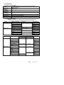
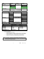
Instruction Manual
MODEL 382860
True RMS Power MultiMeter
1. INTRODUCTION
Congratulations on your purchase of the Extech Model 382860 True RMS Power MultiMeter.
Four LCD displays offer four simultaneous readings e.g. during “POWER” measurements,
simultaneous displays of power, current, AC voltage and power factor can be viewed; AUTO
RANGE always selects the correct measuring range to achieve best accuracy; REL
(Relative) function allows the operator to measure a value with respect to a preset reference
value; CMP (Comparator) function allows a comparative measurement to be made (the
upper/lower limits can be defined); MEM (Memory) and RCL (Recall) functions permit 10
measurements to be stored in memory for later recall; AUTO-POWER-OFF extends the life of
the battery by turning off the meter if neither the rotary function switch nor any button is
operated for 12 minutes. The AC Adaptor required for Power measurements is included.
1
382860
Ver. 1.5
2/01
2. SPECIFICATIONS
2.1 General Specifications
Display
One Main and three Sub 3-3/4-digit (3999 count) LCDs plus 40segment bargraph
Max. Input
DC/AC : 20A
Current
Operating
0 to 104oF (0 to 40°C), relative humidity: <75%, not wetting
Conditions
Storage
0 to 122oF (-10 to 50°C), relative humidity: <76%, not wetting
Conditions
Power
9V Battery: NEDA 1604 9 V or 6F22
Dimensions
7.36x3.3x1.34” (187x84x34mm)
Weight
9.8oz (305g)
2.2 Range Specifications
NOTES: Accuracies are % of reading and specified at 23oC with RH <75%
for a period of 1 year after production. Warm-up time is 1 minute.
Mode
Measuring Range
Accuracy
Resolution
DC Voltage
400 mV
± (0.3% + 1dgt)
100 µV
4V
1 mV
40 V
10 mV
400 V
100 mV
1000 V
± (0.5% + 1dgt)
1V
DC Current
± (1.0% + 1dgt)
400 µA
0.1µA
4mA
1 µA
40mA
± (0.8% + 1dgt)
10 µA
400mA
100µA
4A
± (1.5% + 5dgt)
1mA
20A
10mA
Mode
AC Voltage
Measuring Range
400 mV
Accuracy
40Hz-1KHz
1KHz–10KHz
± (0.8%+3dgts) ± (2.5%+5dgts)
0.1mV
4V
1mV
40 V
10mV
400 V(<200V)
400V(<400V)
100mV
± (1.0%+3dgts)
N/A
750 V
AC Current
Resolution
400 µA
4mA
1V
± (1.5%+3dgts)
± (2.5%+5dgts)
0.1µA
1µA
40mA
10µA
400mA
4A
20A
100mV
N/A
± (2.0%+5dgts)
2
100µA
1mA
10mA
382860
Ver. 1.5
2/01
Mode
Frequency
(Sensitivity:>300mVrms)
Temperature
Mode
Resistance
Capacitance
Diode Test
Continuity Check
Mode
Power Measurements
AC Current
AC Voltage
True Power
True Power
Phase angle (cosine)
Power Factor
Measuring
Range
4kHz
40kHz
400kHz
4MHz
40MHz
Accuracy
Resolution
± (0.1% + 2dgts)
-40°C to 200°C
± (3%+5dgts)
+200°C to 1200°C
± (3%+2dgts)
Range
Accuracy
± (0.5% + 1dgts)
400Ω
4k Ω
40k Ω
400k Ω
4M Ω
± (1% + 2dgts)
40M Ω
4nF
±2.0 (rdg + 2digits)
40nF
400nF
4uF
40uF
400uF
Range 0 to 2000mV, Test current 1.5mA
max. at 1 k ohm, Forward Voltage max. 2.0V
400 Ohm; Audible tone < approx. 40 Ohm
1Hz
10Hz
100Hz
1kHz
10kHz
1°C
Resolution
0.1Ω
1Ω
10Ω
100Ω
1kΩ
10kΩ
1pF
10pF
100pF
1nF
10nF
100nF
1mV
Measuring Range
Accuracy
To 16 A
91 to 120V
To 100 W
To 4000 W
- 90 to 90 degrees
00.00 to 1.00
+/-(2%+5dgts)
+/-(3%+3dgts)
+/-(5%+10dgts)
+/-(2%+5dgts)
2.3 Overload Protection
•
400mA AC/DC in the mA -range
•
Resistance Measurement: 40 Mohm overload; Protection : 250 V DC/AC rms
•
Frequency Measurement : 40MHz with max 750V DC/AC rms input voltage
•
Diode Test/Continuity Test : overload protection : 250 VDC/VAC rms
•
Logic Test : max. 39.99 VDC overload protection 250 VDC/VAC rms
Attention: Transistor, capacitance and temperature measurements are not
overload protected. Exceeding the max. input limits can be hazardous to
the user and can damage the meter.
3
382860
Ver. 1.5
2/01
3. METER DESCRIPTION
•
•
•
•
•
•
•
Function Keys:
Power ON/OFF Key
FUNCTION Select Key
Set/Reset Key
AC/DC Ohm/Continuity Key
UP Key
DOWN Key
Backlight Adjust Button
•
•
•
•
Input Terminals
20-A Input Socket
mA-input
COM Socket (- Terminal)
V-ohm Socket (+ Terminal)
4. Safety Notes
•
The multimeter is EMC-tested and corresponds to the following EG-standard:
89/336/EWG
•
This unit is constructed and checked according to DIN 57 41 Part 1/VDE 0411 Part 1,
Safety Requirement for Electronic Measuring Units and Over-voltage Category II (IEC1010-2).
•
This multimeter may only be used in fuse lines which are protected to 15A. The voltage
must not exceed 250 VDC/VAC and the maximum load must not exceed 4000 VA.
Installations in the overload range III according to ICE 664 are not permitted. The unit
and the measuring cables are not protected against arcing (IEC 1010-2-031, section
13.101).
•
If covers are opened, voltage-carrying components may be accessible. Terminals can
also carry voltage. If it is necessary to open the unit for adjustment, maintenance,
repairing or exchange of parts or modules, the measuring unit has to be removed from
all voltage sources
•
Capacitors can still carry voltage, even if the unit has been removed from all voltage
sources.
•
Please make sure to use new fuses of the proper rating. Do not use repaired fuses and
do not bridge the fuse holders.
•
Use special caution when working with voltages above 25V (AC) and 35 V(DC). Such
voltage may cause a hazardous electrical shock if electrical conductors are physically
touched.
•
Make sure before each voltage measurement that the unit is not set to the ampere
range.
•
Before changing the measurement range, remove the probe tips from the object to be
measured.
•
Before each measurement, check the meter and test leads to make sure they are not
damaged.
•
Do not use the meter in areas with adverse environmental conditions or where
flammable gas, steam or dust may exist. For your own safety, avoid getting the meter
and test leads damp or wet.
4
382860
Ver. 1.5
2/01
•
•
•
•
•
•
To avoid an electrical shock, don’t touch directly or indirectly the test probes and the test
points during measurement.
To avoid serious electrical shock and/or instrument damage, do not apply more than 500
VDC/VAC rms between any meter input terminal and earth ground.
Do not use meter near strong magnetic fields (loudspeakers, magnets), electromagnetic
fields (transformers, motors, coils, relays, contactors, electromagnets etc.), electrostatic
fields (charge/discharge), and Transmission antennas or HF-generators.
Don’t switch on the measuring unit immediately after bringing it in from a cold to warm
room. Condensed water might impair or destroy your unit. Give the unit time to warm up
to room temperature before switching it on.
Safe meter operation is questionable if the unit shows visible damage, the unit does not
appear to work properly, or long-term storage under unfavorable conditions has taken
place.
For measurements, use only test-leads which are supplied with the meter or equivalent
types. The supplied test-leads are rated for a maximum of 1200V. The maximum rating
of the multimeter is 1000 VDC max or 750 VAC rms. Use special caution when working
with voltage above 25 V AC and above 35 V DC.
SAFETY SYMBOLS
This symbol adjacent to another symbol, terminal or operating device
indicates that the operator must refer to an explanation in the Operating
Instructions to avoid personal injury or damage to the meter.
WARNING
CAUTION
MAX
500V
This WARNING symbol indicates a potentially hazardous situation, which if
not avoided, could result in death or serious injury.
This CAUTION symbol indicates a potentially hazardous situation, which if
not avoided, may result in minor or moderate injury, or damage to the
product or other property.
This symbol advises the user that the terminal(s) so marked must not be
connected to a circuit point at which the voltage, with respect to earth
ground, exceeds the referenced VAC or VDC.
This symbol adjacent to one or more terminals identifies them as being
associated with ranges that may, in normal use, be subjected to particularly
hazardous voltages. For maximum safety, thermometer and its test leads
should not be handled when these terminals are energized.
5
382860
Ver. 1.5
2/01
5. BASIC METER OPERATION
5.1 Quick Start
•
Connect the test leads to the meter
•
Press the “ON/OFF” key to power the meter.
•
Turn the rotary function switch to the desired measurement position. The
meter is now ready for “normal” measurement operation.
•
To select an advanced function, press the FUNCTION key. The available
functions will appear on the top of the LCD display. Press FUNCTION again to
scroll through this function list. Press the SET/RESET key to select an
advanced function. These functions are explained in detail in Section 5.4
•
To exit this menu, press the SET/RESET key twice (in some of the modes you
may have to press the FUNCTION key after the two SET/RESET key
presses).
5.2 Function Key Explanations
•
ON/OFF Key: Press the “ON/OFF” key to toggle the meter ON and OFF
•
FUNCTION Key: Press once to enter the advanced function menu. The
user can then select Data Hold DH, Range Hold RH, Auto Hold AH, Relative
REL, Memory MEM, Recall RCL, and Compare CMP functions. Each
function is explained in detail in Section 5.4.
•
SET/RESET: Used for advanced features explained in Section 5.4.
•
DC/AC Ohms/Continuity Key: Press this key to: Toggle between DC/AC
units and switch from resistance measurement to audible continuity check
modes
•
UP/DOWN Keys: Used to:
1. Enter reference values in the REL or CMP modes
2. Address stored values in the MEM and RCL modes
3. Manually set the measurement range in the R-H function mode
4. Scroll through advanced Functions list (UP=forward,
DOWN=backward)
•
BACKLIGHT ADJUST Key (circular, blue-colored button): Press this key
to deepen the LCD backlight effect. The backlight extinguishes after a 15second period of non-use to save battery life and illuminates again when a
keypress is sensed by the meter.
5.3 Input Terminal Designations
•
Transistor Socket hFE (PNP NPN)
This terminal, located to the right of the Rotary Selector Switch, is where
transistor devices are inserted for testing. The eight pole transistor terminal is
lettered symmetrically with (E) Emitter, (B) Base, and (C) Collector. Insert the
transistor pins according to transistor type. Remember to remove any voltage
to components before measuring.
•
Multi-Purpose Capacitor/Temperature Input Socket PLUS CMOS Signal
Output
This socket is located to the left of the Rotary Selector Switch. Discharged
capacitors and Type K temperature probes to be measured are inserted in
here. Observe correct polarity. The CMOS output signals are also available
here (see Section 8).
•
20A Input Terminal
For DC/AC current measurements to 20A max, insert the Red test-lead to this
input socket.
Attention: During current measurements the rotary switch must not be set to
voltage positions.
6
382860
Ver. 1.5
2/01
•
•
•
m A-Measuring Socket
For DC/AC mA current measurements below 400mA, insert the Red test-lead
to this terminal.
COM (Common or Negative Input Terminal
For all measurements, except capacitance, temperature and transistor
measurements, the Black test lead is connected here
V/Ohm -Socket
For measurements of voltage, frequency, resistance, continuity, diode and
logic, insert the Red test lead into this terminal.
5.4 Advanced Function Information
•
Analog Bargraph: The Bargraph consists of 43 segments and responds faster
than the LCD. If the meter’s measuring range is exceeded, “OL” is displayed on the
LCD and the Bargraph segments will flash. An audible warning tone will sound for
all functions except resistance, diode, and temperature in an overload condition.
•
Data-Hold “D-H”: In this mode, you can freeze a reading in the center sub-LCD
display. Press the FUNCTION key then the SET/RESET keys to activate Data
Hold. The center sub-display will indicate the held reading. Press SET/RESET
again to freeze a new reading. Press the FUNCTION key to exit the Data Hold
mode.
•
Range Hold “R-H”: Press the FUNCTION key twice then the SET/RESET key
once to access this mode. This function allows the user to switch off automatic
range selection (Auto Range) and set the measuring range manually. Each time
the UP or DOWN button is pressed, the decimal point is moved one position to the
left or to the right, the units of measure are changed respectively (e.g. from KHz to
MHz during frequency measurement). To return from this function mode, press the
SET/RESET key.
•
Auto Hold A-H: In this function, the meter will automatically record the
MIN/MAX/AVG readings taken since this mode was accessed. These values are
continuously updated. To access A-H, press the FUNCTION key three times. Then
press the SET/RESET key once. Use the UP and DOWN keys to select the
decimal location for the MIN/MAX/AVG readings. If you fixed the range using
Range Hold R-H (explained above), press the SET/RESET key once again. The
MIN-value is shown on the left sub-display, the MAX-value on the right sub-display,
and the AVG on the center sub-display. Press SET/RESET key to return to normal
meter operation.
•
REL(Relative): The relative mode enables the operator to compare a pre-set
reference value (displayed in the right-most sub-LCD) to subsequent readings.
Press the FUNCTION key four times and then press the SET/RESET Key once.
Set the polarity of the reference value via the UP/DOWN keys. Press the
SET/RESET key when polarity is set. Use the UP/DOWN keys to set the desired
reference value and its decimal point (use the SET/RESET key to move through
the digits. When a digit is flashing it is ready to be changed via the UP/DOWN
keys. Press the SET/RESET key repeatedly until the digits cease flashing when
editing is complete. Press the SET/RESET key once more and the meter’s center
sub-LCD will now display the difference (offset) between the stored reference value
and the actual readings, while the present (actual) measurement displays on the
Main LCD. The left sub-display will show the difference in % and the right subdisplay will continue to show the preset reference value.
7
382860
Ver. 1.5
2/01
•
MEM (Memory): Up to 10 measurements (0 to 9) can be stored and recalled.
Press the FUNCTION key five times then press the SET/RESET key once to store
the present measurement value in the first available memory location. The memory
location number will flash to the upper left of the left-most sub-LCD. The
memorized reading is shown on the center sub-LCD. Use the UP/DOWN keys to
scroll to the next free memory location. Take another measurement and press the
SET/RESET key to store it. If a memory location number which has been used
before is selected, the previous value is updated (erased) with the new
measurement value. If you accidentally exit the function mode by pressing the
SET/RESET key too many times, the memory is not erased. It can be “recalled”
using the RECALL function which follows…
•
RCL(Recall): This function recalls memorized readings to the LCD. Press the
FUNCTION key 6 times until the RCL icon flashes. Press the SET/RESET key
once. The memory location reference number flashes to the upper left of the leftmost sub-LCD. Press the UP or Down keys to select a memory address (a number
from 0-9 where the measurement has been stored). Press the SET/RESET key
again to recall the reading memorized in the selected location. The recalled value
(ref. No. 0) will appear on the left sub-display; the 2nd recalled value (ref. No. 1)
appears on the center sub-display and the 3rd recalled value (ref. No. 2) appears on
the right side sub-display, and so on for the remaining locations.
•
CMP (Comparison): Comparison mode allows readings to be compared to user
programmable High/Low setpoints. Press the FUNCTION key and then the DOWN
key. Press the SET/RESET key once and the word “LOW” should begin flashing
above the left-most sub-LCD. Press the SET/RESET to begin editing the LOW user
setpoint. Use the SET/RESET key to move from digit to digit and use the
UP/DOWN keys to change a digit’s value. When done, press the SET/RESET key
until the LOW setpoint value ceases flashing. The word “HIGH” will begin flashing
over the right-most sub-LCD. Edit the HIGH setpoint in the same manner as the
LOW setpoint. After both reference values have been defined press the
SET/RESET key again. The R-H (Range Hold) icon will begin flashing. Set the
measurement range via the UP/DOWN keys. On the center sub-display “LO”
appears for readings less than the low reference value, “Hi” is displayed for
readings higher than the highest reference value, and “Pass” is displayed for
readings in the region between the low and high reference values. To exit CMP
mode, press the FUNCTION key.
•
AUTO-POWER-OFF extends the life of the battery: if neither the rotary function
switch nor any button is operated for 12 minutes the DMM is automatically turned
off. During active “communication” of the multimeter with a PC, AUTO-POWEROFF is disabled.
8
382860
Ver. 1.5
2/01
6. MEASUREMENT INSTRUCTIONS
6.1 Voltage AC/DC Measurements (True RMS for AC Voltage)
Attention: Never exceed the maximum input limits (1000VDC or 750 VAC
rms).Keep hands away from circuits where 25 VAC rms or 35 VDC exists.
To measure DC / AC voltage proceed as follows:
1. Set the rotary function switch to the desired position (mV or V)
2. Press the DC/AC key until the desired units are displayed (AC or DC).
3. Connect the test-lead tips to the object under test (load, circuit etc.)
4. Read the LCD
AC / DC Voltage Displays
During True RMS AC voltage measurements, the right-most sub-LCD display will
show the dB-value of the AC voltage, the middle sub-display shows the frequency
and the main display the ACV measurement. During DC voltage measurements,
the left sub-display updates the measurement 1 second later than the Main LCD,
the middle sub-display 2 seconds later, and the right sub-display 3 seconds later.
6.2 AC / DC Current Measurements (True RMS AC Current)
1. Select the desired Current range via the rotary switch (4 mA / 400 mA / 20 A).
2. Press the DC/AC button to select AC or DC Current units
3. “Break” the circuit to be measured and connect the test-leads in series with
circuit under test.
4. Power the device to be measured (circuit load etc.) and read the current on
the LCD. During AC current measurements, the middle sub-display will show
the frequency of the measurement and the main display indicates the current
measurement.
5. During DC current measurements, the left-most sub-display is updated one
second later than the main LCD. The middle sub-display two seconds later
and the right sub-LCD three seconds later.
Attention: Never measure current in circuits where over 250 VDC/VACrms may be
present. The meter fuses are designed for 250 V max. Measure circuits in which
15A fuse protection is provided only. Never measure circuits where Power
exceeds 4000 VA. Current measurements of 20A may only be taken for 30
seconds at 15 minute intervals (DO NOT exceed 20A).
6.3 Continuity Test
Continuity is a low resistance test permitting the testing of fuses, bulbs, test leads,
cable, circuits, etc. Set the rotary switch to the Ohm position and press the DC
Ohm/AC button until the music symbol displays. Connect the test-lead tips to the
device under test. If the resistance is < approx. 40ohms an audible tone sounds.
The left sub-LCD updates one second later than the main LCD, the middle subdisplay 2 seconds later, and the right-most sub-display 3 seconds later.
6.4 Resistance Measurements
Attention: Make sure all objects, circuits and
components under test are NOT powered!
1.
Set the rotary switch to the Ohms position. Press the AC/DC key so that the
continuity musical symbol does NOT appear on the LCD.
9
382860
Ver. 1.5
2/01
2.
Connect the test-leads to the device under test. Ensure that all power is
removed from devices under test. Auto Range selects the appropriate range
automatically.
3. Normally the resistance of the test-leads can be disregarded (approx. 0.1 to
0.2 Ohm). However, this small value can cause inaccuracy in the 400 Ohm
range. To determine the error before measurement, short the test-lead tips
and read the resistance value on the display. Subtract this value from
readings to cancel lead resistance errors.
4. During resistance tests, make sure that the contact between test leads and
circuits is optimized. Make sure the test points are free of dirt, oil or solder
flux, etc. since these may seriously influence the measurement.
5. For resistance measurements >4M, the display will take several seconds to
stabilize.
6. The left-most sub-LCD updates one second later than the main LCD, the
middle sub-display 2 seconds later and the right-most sub-display 3 seconds
later.
6.5 Diode Test
Attention: During diode tests, ensure that components and circuits under test are NOT
powered. All existing capacities must be discharged.
1.
2.
3.
4.
5.
6.
Set the Rotary Switch to the diode symbol position. The diode icon will be
displayed. Manual range selection is not possible during diode tests.
Connect the test-lead tips to the object under test. The RED probe-tip
connects to the anode of the device under test and the BLACK test-lead tip
connects to the cathode.
A diode’s forward voltage should measure approx. 0.25 V (Germanium) or 0.7
V (Silicon), if the diode is GOOD.
Reverse the probe-tips (Red to the cathode and Black to the anode) to check
the diode’s reverse status.
If “OL” (overload) is displayed, the diode is open or measures above 2.0 V. If
a value between 0 V and approx. 2.0 is displayed, then a good forward
voltage drop exists.
During diode tests the center sub-display indicates GOOD if the diode is o.k.
If the diode is defective (short circuit) or low resistance short then SHORT is
displayed. If the diode is defective due to high resistance or if the test leads
are accidentally reversed (red to cathode and black to the anode) then
“OPEN” for (open circuit) is displayed.
NOTE: Checking LED components in Diode Test mode
The meter’s test voltage in diode test mode is sufficient to “illuminate” most
(low current) LEDs. If the LED has an operating voltage of more than 2.0 V,
the meter will falsely indicate that the LED is defective when it actually may be
good.
6.6 Frequency Measurement
Attention: Observe the max. input limits. Never connect voltages over 750 VDC/VAC
rms. It is hazardous to touch the terminals or probe tips when measuring voltages >
25VAC/35 VDC. Disconnect the test-leads from the contact points when measuring
voltage (over 25 VAC or 35 VDC) and before changing the meter function and range
1.
2.
Set the rotary function switch to the “FREQ” position and insert the test leads
to the meter
Connect the test-lead tips to the frequency source under test (generator, etc.).
For the best accuracy, the use of BNC-Cables is strongly recommended.
During frequency measurements, the right sub-display shows the dB-value of
the AC voltage, the middle sub-display shows the AC voltage “V” and the
main display: the present input value (frequency).
10
382860
Ver. 1.5
2/01
6.7 Capacitance Measurement
Attention: When shorting capacitors (discharging), high-energy discharge of
electricity may occur. Do not touch the terminals if there are capacitors with
voltages over 35 VDC or 25 VAC. Use special caution in environments where
flammable gases, steam or dust could trigger combustion
1.
2.
3.
4.
Discharge each capacitor before testing. Never attempt to measure the
capacitance of a charged capacitor, you might damage your multimeter.
Set the rotary function switch to the “CAP” position.
Capacitance measurements are only possible using the meter’s capacitor
input socket located to the upper left of the Rotary Switch.
Give the meter approx. 2-3 seconds to stabilize during capacitance
measurements. The left-most sub-LCD updates 1 second later than the Main
LCD, the center display 2 seconds later and the right sub-LCD 3 seconds
later.
6.8 Transistor Test
Attention: The transistor socket is not protected against overload. The
Warranty is void if external transistor sockets are built and used by the
operator.
To Check that a Transistor is working properly
1. Set the rotary function switch to hFE position.
2. Insert transistor in the appropriate transistor socket and read hFe on the LCD.
3. During measurements of small power transistors, the left-most sub-LCD
updates 1 second later than the Main LCD. The center display 2 seconds later
and the right 3 seconds later.
Important Transistor measurement notes:
•
Observe the sequence of connections (E-B-C) for the transistor
•
Some Darlingtons or special (power) transistors contain internal base-toemitter resistances that could cause erroneous measuring results.
•
The hFE-measuring value is not an absolute measurement. It only indicates if
the transistor is operating or not. The true amplification of a transistor depends
on its operating current. This multimeter supplies a base current up to 10 uA;
the collector current is measured to calculate the respective hFE-value.
•
It is not possible to measure transistors which are connected in a circuit.
•
It is not possible to measure the hFE-value of FETs or other unipolar
transistors.
•
If a low power transistor (e.g. BD 242 etc.) has terminals that do not fit the test
socket, do not force it into the test socket, as the meter terminals could be
damaged.
6.9 Temperature Measurement
The main display will show the temperature in degrees centigrade, while the middle
sub-display will show the temperature in degrees Fahrenheit
1. Select “TEMP” with the rotary function switch.
2. Insert in the temp probe into TEMP/CAP socket, observe the correct polarity
(narrow and wide tongue). Type K thermocouple probes are to be used
exclusively.
6.10 Logic Test This function allows logic level tests in digital circuits.
1. Switch the meter power ON.
2. Set the rotary switch to the “LOGIC” position. The LCD displays “rdy” (ready).
3. Connect the test-leads as follows: COM-input socket (black lead); V-Ohm
socket (red lead).
11
382860
Ver. 1.5
2/01
4.
5.
6.
Now connect the other end of the black test-lead to the “ground” point of the
digital circuit and the red test-probe to the supply voltage point (V+ or Vcc)
When all leads are connected, press the SET/RESET key to save the “High”
Reference Level.
With the black test-lead-at ground, move the red test-probe from the supply
voltage to the desired test points. The multimeter will immediately display one
of the three modes. HIGH MODE: If the level exceeds 70% of the stored
supply voltage “Hi” is displayed. LOW MODE: If the level falls below 30% of
the stored supply voltage, “Lo” is displayed. PASS MODE: If the level is
between the reference values (31% and 69% of the supply voltage), “----“ is
displayed.
7. POWER MEASUREMENTS
For the measurement of power, the Power Adaptor (included) is required. This adaptor
consists of a three-prong plug and three-prong socket on one end (for connection
to loads under test) and a multi-plug on the other end (for insertion into meter's
input terminals).
7.1 Test Procedure
1. The Power Adaptor must be connected to the meter before Power
measurements can be made. Once connected, set the Rotary Switch to the
Power position.
2.
Connect the multi-plug side of the adaptor to the meter's input terminals. The
multi-plug is labeled with '20A' on the left, 'COM' in the middle, and 'V/ohms'
on the right. Always connect the correct contacts for all plug connections. The
labeling on the Power Adaptor matches the meter's labeled input terminals for
convenience.
3.
Connect the appliance/load under test (not powered) to the socket of the
Power Adaptor.
4.
Power the load under test by inserting the three-prong plug into a 117VAC
outlet. Readings can now be observed on the LCDS.
5.
The maximum AC current that the meter can accept is 16A for short periods of
time (30 seconds or less). Never exceed this limit. 12A can be safely
monitored continuously.
WARNING: If the connection between adpator and meter is incorrect, severe meter
damage will result. In addition, a risk of electric shock exists. Finally, DO NOT select
any other range other than POWER while the adaptor is connected to the meter.
Serious meter damage and injury can occur.
7.2 Three Modes of Power Measurement Displays
There are three modes of Power Measurement Displays. These modes have
different Main LCD and Sub-LCD displays related to power. Mode 0 is the initial
mode that the meter will be in when the POWER position is selected with the
Rotary Switch. A zero will display to the upper left of the left-most sub-LCD
indicating Mode 0. Use the UP and DOWN arrow keys to scroll through modes 0
through 2. The digit to the upper left of the left-most sub-LCD indicates the present
mode. Refer to the Table below for an overview of the display modes for the Main
LCD and the three Sub-LCDs. Then refer to the explanations below for
accumulated watts, cost, etc.
12
382860
Ver. 1.5
2/01
Mode 0
Main LCD
Watts
Mode 1
Watts
Mode 2
Accumulated
Watts
Left sub-LCD Center sub-LCD
Right sub-LCD
AC Load
AC Voltage
Phase angle (cosine)
Current
Rate Cost/hour Accumulated
Accumulated consumption
Watts
cost in $
EDIT the Rate
Unit 1KW/Hr
NO DISPLAY
Cost/hour
TABLE 1: Three Power Measurement Display Modes
7.2.1 Explanation of terms in TABLE 1
•
Watts: True Power reading of load/appliance measurement
•
AC Load Current: Current measurement for load/appliance under test
•
AC Voltage: Voltage measurement of load/appliance under test
•
Phase angle: Phase difference (from –90 to +90 degrees) between input
source and load
•
EDIT the Rate Cost per hour in $: This is where the user programs the Cost
per hour (instructions on how to set this value are given in Section: 7.3)
• Accumulated Consumption Cost in $: This is the total cost of consumption
monitored since measurement session began (displayed in US$)
•
Accumulated Watts: Wattage accumulated from when measurement session
began up to the present (displayed in KW/H).
•
KW/H: Kilowatt hours
•
Unit 1 KH/H: Reference value of 1KW/H
7.3 Programming Cost per Hour
1. Go to mode 2 using the UP/DOWN keys to scroll through the modes. The mode
designator is the digit to the upper left of the left-most sub-LCD.
2. The left-most sub-LCD is where the Cost per Hour is programmed.
3. Press the SET/RESET key to begin editing the left most digit will flash. Enter the
desired value via the UP/DOWN keys. While programming, to move to the next
digit for editing, use the SET/RESET key. Digits are selected and ready for
editing when they are flashing.
4. Press the SET/RESET key until the digits cease flashing when finished editing
the cost per hour value and then measure power in the desired mode
Note: Based on the consumption cost per hour programmed, the meter displays
the expected rate cost per hour automatically. Currency is displayed in US dollars.
7.4 Storing and Clearing Accumulated Measurement Data
The meter memorizes accumulated reading data when the POWER position of the
Rotary Switch has been changed to another function after Power measurements
have been made (this activates the memory utility). To recall accumulated data, reselect POWER on the Rotary Switch, the meter displays stored data in EEPROM.
To clear accumulated readings: Set the Cost per KW/H to 0000.0 in mode 2 (left
sub-LCD display).
7.5 General Power Measurement Notes:
1. When POWER is selected via the Rotary Switch, automatic power-down
works only when the watt measurement reading is zero.
2. When POWER is selected on the Rotary Switch, the FUNCTION key will not
operate when pressed.
3. To save (store) the cost per hour, KW/H, and accumulated cost data, press
the FUNCTION key or turn the Rotary Switch to another range AFTER
DISCONNECTING THE POWER ADAPTOR. Never change the Rotary
13
382860
Ver. 1.5
2/01
4.
Switch setting from POWER with the Adaptor connected. Serious injury and
meter damage can result.
The meter always memorizes the last input values of cost per hour, KW/H,
and accumulated costs that were measured.
8. CMOS Signal Output
Your meter is equipped with a “Function Generator” which supplies outputs of ten preset
frequencies with a voltage max. of 3.3V. To “tap off” the signal, insert the enclosed
signal adaptor into the capacitor socket, observing the correct polarity. The other end of
the adaptor has two small alligator clips. To change the multimeter into a signal
generator and to select the output frequency, follow these steps.
1. Select “SIG OUT” with the rotary function switch.
2. Connect the optional signal adaptor to the capacitance measuring socket of
the multimeter.
3. Turn on the multimeter
4. In the basic function mode, the reference number is displayed in the left subdisplay, the main display will show the respective frequency “0.010 KHz
(=10Hz). In the middle sub-display the external DC input voltage is displayed
in “V” (max. 40V).
5. To select other output frequencies use the UP/DOWN keys. Refer to the list
below for frequency and reference numbers.
0.010 KHz =
10Hz,
reference no. 0
0.050 KHz =
50Hz,
reference no. 1
0.060 KHz =
60Hz,
reference no. 2
0.100 KHz =
100Hz,
reference no. 3
0.400 KHz =
400Hz,
reference no. 4
1.010 KHz =
1010Hz,
reference no. 5
2.021KHz =
2021Hz,
reference no. 6
4.042KHz =
4042Hz,
reference no. 7
8.084KHz =
8084Hz,
reference no. 8
10.24kHZ =
10240Hz,
reference no. 9
Attention: Never short the output of the signal generator. The output terminal and the
meter could be damaged.
9. PC INTERFACE FEATURE
9.1 Hardware Setup
Connect the supplied RS-232C cable between the meter’s com port and the computer’s
serial port. Power the meter and the computer and then load the software.
9.2 Software for PC Interface
Two data acquisition programs are included: a DOS version (ScopeView) and a
Windows version (MultiView).
9.2.1 Using the DOS Software
Follow these steps to install and run the MS-DOS software.
1. Insert the supplied diskette in your computer’s 3 ½-inch floppy drive.
2. Create a directory on your hard disk . For example, to make a directory
called METER type.: cd \ (ENTER) then, type md METER (ENTER)
3. Change to the directory you just created. For example, if the directory is
METER, type: cd \ METER (ENTER)
4. Copy the files from the GRAPHIC sub-directory on the supplied program
floppy disk to your hard disk. For example, type: copy a:\GRAPHIC c:
5. To run the program, type METEX (ENTER) Follow the on-screen help for
specific operating instructions.
14
382860
Ver. 1.5
2/01
9.2.2 Using the Windows Software
Follow these steps to install and run the Windows software
Note: The following steps assume a basic knowledge of Microsoft Windows. This
software requires Microsoft Windows, Version 3.1 or later and a VGA or EGA
display.
1. Start your computer and run Windows.
2. Insert the supplied diskette in your computer’s 3 ½-inch floppy drive.
3. For Windows 3.1 go to Program Manager and pull down the FILE menu.
Select RUN.
4. For Windows 95, choose RUN from the START menu.
5. At the prompt, type:
6. a:\scope\setup (ENTER) (if you placed the diskette in Drive A) or
b:\scope=setup(ENTER) (if you placed the diskette in Drive B)
7. Follow the on-screen prompts to complete the installation.
8. To run the program, double-click the SCOPE-VIEW icon, Follow the onscreen help for specific operation instruction. Also, refer to the README file
in the diskette’s SCOPE subdirectory for operation hints.
10. MAINTENANCE
10.1 Fuse Replacement
Remove power to the meter and removal all connected cables and probes. Use a
suitable Phillips screwdriver to carefully open the case. Remove the defective
fuse(s) and replace it with a new one of the same type and nominal current (0.8A
fast blow, 250 V); usual name: F 0.8A/250A or F 800Ma/250V. For the amperage
range 20 A ultra rapid, 250V; usual name F 12A/250V (BUSSABC12). After the
fuse has been exchanged close the cabinet.
10.2 Battery replacement
Remover power to the meter and disconnect any cables or test leads. Open the
battery compartment by removing the rear battery compartment screw with a
Phillips screwdriver. Exchange battery and reinstall the battery compartment
cover.
(
Tech Support Hotlines
781-890-7440 ext. 200
[email protected]
www.extech.com
15
382860
Ver. 1.5
2/01
11. REPAIR AND CALIBRATION SERVICES
Extech offers complete repair and calibration services for all of the products we
sell. For periodic calibration, NIST certification or repair of any Extech product, call
customer service for details on services available. Extech recommends that
calibration be performed on an annual basis to insure calibration integrity.
12. WARRANTY
EXTECH INSTRUMENTS CORPORATION warrants the basic instrument to be free of
defects in parts and workmanship for one year from date of shipment (a six month
limited warranty applies on sensors and cables). If it should become necessary to return
the instrument for service during or beyond the warranty period, contact the Customer
Service Department at (781) 890-7440 for authorization. A Return Authorization (RA)
number must be issued before any product is returned to Extech. The sender is
responsible for shipping charges, freight, insurance and proper packaging to prevent
damage in transit. This warranty does not apply to defects resulting from action of the
user such as misuse, improper wiring, operation outside of specification, improper
maintenance or repair, or unauthorized modification. Extech specifically disclaims any
implied warranties or merchantability or fitness for a specific purpose and will not be
liable for any direct, indirect, incidental or consequential damages. Extech's total liability
is limited to repair or replacement of the product. The warranty set forth above is
inclusive and no other warranty, whether written or oral, is expressed or implied.
Copyright © 1999 Extech Instruments Corporation. All rights reserved
including the right of reproduction in w hole or in part in any form.
16
382860
Ver. 1.5
2/01