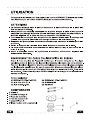
1
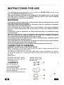
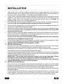
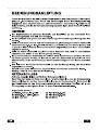
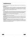
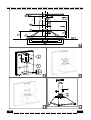
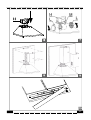
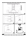
Cooker Hood
Dunstabzugshaube
Hotte
DKP 2010 X
DKL 5010 X
Instructions Booklet
Bedienungsanleitung
Mode d’emploi
Instructieboekje
GEBRUIKSAANWIJZINGEN............................................ 12
WAARSCHUWING! ....................................................................... 12
AANSLUITING OP HET ELEKTRICITEITSNET ..................................... 12
INHOUD ...................................................................................... 12
INSTALLATIE ................................................................ 13
WERKING .................................................................... 14
ONDERHOUD ............................................................... 15
INSTRUCTIONS FOR USE
This appliance has been designed for use as either an EXTRACTION (ducting to the
outside) or RECIRCULATION (filtering) hood.
The measurements contained on the drawings in this booklet refer to two models
of cooker hood. Therefore, it is essential that you refer to the correct drawing
when taking measurements for installation.
WARNINGS!
- The minimum distance between the cooking surface and the metal grease filters on the
underside of the hood must be 650mm.
- This cooker hood must be installed in accordance with the installation instructions
and all requirements must be adhered to.
- If the room where the cooker hood is to be used contains a fuel burning appliance
such as a central heating boiler then its flue must be of the room sealed or balance
flue type.
- If other types of flue or appliances are fitted ensure that there is an adequate supply
of air to the room.
- When the cooker hood is used in conjunction with appliances supplied with energy
other than electricity, the negative pressure in the room must not exceed 0.4 mbar to
prevent fumes being drawn back into the room by the hood.
- The ducting system for this appliance must not be connected to any ventilation system
which is being used for any other purpose.
- The ducting system for this appliance must not be connected to any existing ventilation
system which is being used for any other purpose.
- Do not leave naked flames or carry out flambe cooking under this cooker hood.
CONNECTION TO THE MAINS
WARNING: DOUBLE INSULATED DO NOT EARTH
Before connecting to the mains supply ensure the mains voltage corresponds to the
voltage on the rating plate inside the hood.
This appliance is fitted with a 2 core mains cable and must be permanently connected to
the electricity supply via a double-pole switch having 3mm minimum contact gap on
each pole.
Aplied norms:
EN 60355-1/88 (CEI 61-50/89)
CEI EN 61000-3-2/95
EN 60335-2-31 (CEI 61-92/91)
CEI EN 61000-3-3/95
CEI EN 55014/94
EN 55104/95
CONTENTS
-
2 No Wall Brackets C
1 No Locking Washer D
1 No Ducting Flange E
1 No 150-120mm Ducting Spigot G
1 No Air Deflector H
2 No Charcoal Filters L (Optional)
1
INSTALLATION
1 -
2 3 4 -
5 -
6 7 7A
-
7B
-
-
2
The cooker hood must be installed centrally over a cooking appliance. The minimum
distance between the cooking surface and the metal grease filters on the underside of
the hood must be at least 650mm. To install the hood proceed as follows: Firstly, draw a vertical line approximately 950mm up the wall from the centre of the cooking
appliance. Secondly, draw two vertical lines 90mm either side of the first line up to the
ceiling. Thirdly, draw four horizontal lines through the vertical lines at Y-J-X2-X1 as
illustrated in fig. 1 to give you your drilling positions.
Drill eight 8mm diameter holes at X1-X2-J-Y and insert the plastic rawl plugs supplied as
illustrated in fig. 2 ensuring the brackets are fitted as shown in the blow up.
Secure the two brackets C to the wall inserting two of the screws supplied through the
two holes on line X1-X2 as illustrated in fig. 2.
Secure the locking washer D to the wall inserting one of the screws supplied through
hole Y as illustrated in fig. 2 ensuring the washer is fitted with the recess to the wall
as shown in the blow up.
Slide the canopy down the wall to locate the key hole over the washer then secure the
canopy to the wall by inserting two of the screws supplied through the two outer holes in
the rim of the canopy J1 and J2 as illustrated in fig. 3.
To prevent the canopy from accidentally being dislodged from the wall at anytime
fit the final screw supplied through hole J3.
Fit the ducting flange E over the rectangular air outlet in the top of the canopy rim using
the two 2.9mm self tapping screws provided as illustrated in fig. 4.
EXTRACTION OR RECIRCULATION INSTALLATION:
EXTRACTION (Ducted)
When used in the extraction(ducted) mode contaminated air enters the cooker hood
through the metal grease filters and passes out through ducting to the outside.
When the hood is ducted to the outside the 150 to 120mm diameter ducting spigot G
must be fitted onto the ducting flange E as illustrated in fig. 5.
The (optional) ducting required must be 120mm in diameter and made from fire retardent
material. Where flexible ducting is fitted it should not be turned through very tight bends
as this could impair the performance of the hood.
IMPORTANT: The ducting used inside the chimney must not be larger than 120mm
in diameter as this could subsequently prevent the chimney fitting correctly.
The ducting system for this appliance must not be connected to any ventilation
system which is being used for any other purpose.
RECIRCULATION (Filtered)
When used in the recirculation mode (filtered) contaminated air enters the cooker hoDD
through the metal grease filters, passes through the (optional) cleansing charcoal filters
where it is purified and passes out into the kitchen through the grilles in the chimney.
When the hood is fitted in the recirculation mode the air deflector H should be fitted as
illustrated in fig. 6.
Fit the (optional) charcoal filters by repeating the following operation on each side of the
motor housing. Place the two key hole slots in the filter L over the tabs on the motor
housing M and turn the filter clockwise to lock the filter in position as illustrated in fig. 7.
- WARNING: It is a possible fire hazard if the metal grease filters are not cleaned and
the charcoal filters replaced regularly.
8
FITTING THE CHIMNEY
- To fit the (longer) upper chimney A, place the top edge of the chimney over the bracket C
as illustrated in fig. 8 and secure the chimney using two of the 2.9mm self tapping screws
provided.
- The distance in the height between the fixing holes X1 and X2 is determined by the
height of the upper chimney A.
- To fit the (shorter) lower chimney B, apply slight force to the two rear edges to increase
the width of the apperture, then sleeve the chimney B over the chimney A as illustrated
in fig. 9.
OPERATION
- The cooker hood functions are controlled by a series of slider or push button switches
mounted on the front of the hood and control the worktop lighting and fan motor speeds.
- This cooker hood will not remove steam.
1 - SLIDER SWITCHES
- A switch controls the wotktop lighting - ON/OFF.
- A switch controls the fan speeds - OFF/ON-1-2-3.
- The red neon lamp illuminates when the motor is switched ON .
2 - PUSH BUTTON SWITCHES
- A switch controls the worktop lighting - ON/OFF.
- A button switches the motor OFF/ON at the low speed setting.
- A button switches the motor to the medium speed setting.
- A button switches the motor to the high speed setting.
- The red neon lamp illuminates when the motor is switched ON.
3 - SPEED SETTINGS
- 1/Low should be selected when simmering or when using only one pan.
- 2/Medium should be selected for cooking when using up to four pans.
- 3/High should be selected when frying or cooking food with a strong odour.
3
MAINTENANCE
N.B. Before carring out any kind of maintenance, cleaning or replacing lamps, disconnect
the hood from the mains supply.
1. Lighting
Comprises two 40W bulbs. To replace the bulbs, proceed as follows (fig.10): Remove
one of the pins at the sides of the lamp cover. Slide the glass towards the side from which
the pin has been removed until the opposite edge has been freed, then pull gently
downwards. Replace the bults and fit the glass again by repeating the above operations
in reverse order.
2. Filters
The metal grease filter should be cleaned every two months or more frequently if the
hood is used consistently and can be cleaned in a dishwasher or by hand using a mild
detergent or liquid soap. When replacing, ensure that they are dry.
The charcoal filter cannot be washed and should be replaced at least every 2 months or
more frequently if the hood is used consistently.
3. Cleaning
When cleaning the hood, it is recommended to use a damp cloth and mild liquid household
cleaner. Never use abrasive cleaning materials,
IMPORTANT: When using a gas hob in connection with the cooker hood never leave the
burners of the hob uncovered while the hood is in use or when the pans have been
removed. It is very important to follow all instructions for cleaning the hood and filters.
There could be a possible fire hazard if the filters are not replaced according to these
instructions.
ATTENTION: The manufacturer declines all responsibility for any damage or injury caused
as a result of not following the instructions for installation, for maintenance and replacement
times of filters indicated (in order to avoid a possible risk of fire when the filters are
saturated with grease).
4
5
6
7
8
9
10
11
GEBRUIKSAANWIJZINGEN
Dit apparaat werd ontworpen voor gebruik als een AFZUIGKAP (luchtafvoer naar buiten)
of als een RECIRCULATIEKAP (filteren).
De afmetingen op de tekeningen in dit boekje verwijzen naar de twee modellen van
kap. Het is daarom essentieel dat u verwijst naar de correcte tekening bij het nemen
van de afmetingen voor de installatie.
WAARSCHUWING!
- De minimum afstand tussen het kookoppervlak en de metalen vetfilters aan de
onderkant van de kap moet 650 mm bedragen.
- De afzuigkap moet worden geïnstalleerd overeenkomstig de installatie-instructies
en alle vereisten moeten worden nageleefd.
- Indien de kamer waarin de afzuigkap zal worden gebruikt een apparaat met een
brandstof bevat zoals een centrale verwarmingsketel, dan moet zijn afvoerbuis van
het type gesloten of geveltoestel zijn.
- Indien andere types rookkanalen of toestellen worden geplaatst, moet u ervoor
zorgen dat er een voldoende luchttoevoer naar de kamer is.
- Wanneer de afvoerkap gebruikt wordt samen met toestellen die voorzien zijn van nietelektrische energie, mag de negatieve druk in de kamer 0.4 mbar niet overschrijden
om te verhinderen dat dampen terug in de kamer gezogen worden door de kap.
- Het afvoersysteem voor dit toestel kan niet worden verbonden met een
ventilatiesysteem dat voor andere doeleinden gebruikt wordt.
- Het afvoersysteem voor dit toestel kan niet worden verbonden met een bestaand
ventilatiesysteem dat voor andere doeleinden gebruikt wordt.
- Laat geen vlammen branden onder de kap of flambeer ook niet onder deze afzuigkap.
AANSLUITING OP HET ELEKTRICITEITSNET
WAARSCHUWING: DUBBEL GEISOLEERD NIET AARDEN
Voor u aansluit op het elektriciteitsnet, moet u kijken dat het elektriciteitsvoltage
overeenkomt met het voltage op het typeplaatsje aan de binnenkant van de kap.
Dit toestel is uitgerust met een tweeaderig netsnoer en moet permanent worden
aangesloten op de elektriciteitsvoorziening via een dubbelpolige schakelaar met een
contactopening van minimum 3 mm op elke pool.
Toegepaste normen:
EN 60355-1/88 (CEI 61-50/89)
CEI EN 61000-3-2/95
EN 60335-2-31 (CEI 61-92/91)
CEI EN 61000-3-3/95
CEI EN 55014/94
EN 55104/95
INHOUD
-
2 No Wandbeugels C
1 No Afdichtingsring D
1 No Flens voor de afzuigbuis E
1 No 150-120mm Pasring voor de afzuigbuis G
1 No Luchtstroomrichter H
2 No Koolstoffilters (Optioneel) L
12
NL
INSTALLATIE
De afzuigkap moet centraal over een fornuis worden geïnstalleerd. De minimum afstand
tussen het kookoppervlak en de metalen vetfilters aan de onderkant van de kap moet 650
mm bedragen. Om de kap te installeren, ga als volgt te werk: 1) Trek eerst een verticale lijn op de muur ongeveer 950 mm boven het midden van het
fornuis. Trek dan twee verticale lijnen op 90 mm aan elke kant van de eerste lijn naar het
plafond. Trek vervolgens vier horizontale lijnen door de verticale lijnen op Y-J-X2-X1 zoals
geïllustreerd in figuur 1 om u de boorposities te geven.
2) Boor acht gaten van 8 mm diameter in X1-X2-J-Y en plaats de plastic bijgeleverde plugs
zoals geïllustreerd in fig. 2 en zorg ervoor dat de houders geplaatst worden zoals getoond
in de uitvergroting.
3) Bevestig de twee beugels C aan de wand via de twee meegeleverde schroeven door de
twee gaten op lijn X1-X2 zoals geïllustreerd in Fig. 2.
4) Bevestig de afdichtingsring D aan de muur via één van de meegeleverde schroeven door
gat Y zoals geïllustreerd in fig. 2 en zorg dat de ring tegen de muur geplaatst wordt met de
inspringing zoals getoond in de uitvergroting.
5) Schuif de kap naar beneden op de muur om het gat over de ring te vinden en bevestig dan
aan de muur via twee van de meegeleverde schroeven door de buitenste gaten in de rand
van de kap J1 en J2 zoals geïllustreerd in fig. 3.
Om te verhinderen dat de kap per ongeluk van de muur los geraakt, bevestig de
laatste meegeleverde schroef door gat J3.
6) Plaats de flens voor de afzuigbuis E over de rechthoekige luchtuitlaat in de bovenkant van
de rand van de kap met behulp van de 2 zelftappende schroeven van 2,9 mm zoals
geïllustreerd in fig. 4.
7) INSTALLATIE ALS AFZUIGKAP OF ALS RECIRCULATIEKAP
• AFZUIGKAP (met afvoerbuis)
- Wanneer gebruikt als afvoerkap (met afvoerbuis), komt vervuilde lucht de afvoerkap
binnen via de metalen vetfilters en gaat deze lucht via de afvoerbuis naar buiten.
- Wanneer de kap een uitvoer naar buiten heeft, moet de pasring voor de afzuigbuis G met
een diameter van 150 tot 120 mm op de flens voor de afzuigbuis E worden geplaatst zoals
geïllustreerd in fig. 5.
- De (optionele) vereiste afvoerbuis moet 120 mm in diameter zijn en vervaardigd zijn uit
brandvertragend materiaal. Wanneer een flexibele afvoerbuis wordt geplaatst, mag deze
niet worden gedraaid door zeer nauwe bochten omdat dit de prestaties van de kap negatief
kan beïnvloeden.
- BELANGRIJK: - Het afvoersysteem voor dit toestel kan niet worden verbonden met
een ventilatiesysteem dat voor andere doeleinden gebruikt wordt.
• RECIRCULATIEKAP (Met filter)
- Wanneer gebruikt als recirculatiekap (met filter) komt vervuilde lucht in de afvoerkap via de
metalen vetfilter, ze gaat door de (optionele) koolstoffilters waar ze gereinigd wordt en gaat
terug naar de keuken via de roosters in de schoorsteen.
- Wanneer de kap werkt in de stand recirculatie, moet de luchtstroomrichter H geplaatst
worden zoals geïllustreerd in fig. 6.
NL
13
- Plaats de (optionele) koolstoffilters door de volgende handeling te herhalen aan elke kant
van de motorbehuizing. Plaats de twee stukken in de filter L over de lipjes op de
motorbehuizing M en draai de filter met de klok mee om deze op zijn plaats te vergrendelen
zoals geïllustreerd in fig. 7
- WAARSCHUWING: Er is risico op brand indien de metalen vetfilters niet regelmatig
gereinigd en de koolstoffilters niet regelmatig vervangen worden..
8) PLAATSEN VAN DE SCHOORSTEEN
- Om de (langere) bovenste schoorsteen A te plaatsen, plaats de bovenkant van de
schoorsteen over houder C zoals geïllustreerd in fig. 8 en bevestig de schoorsteen via de
bijgeleverde 2 zelftappende schroeven van 2,9 mm.
- Het verschil in hoogte tussen de bevestigingsgaten X1 en X2 wordt bepaald door de
hoogte van de bovenste schoorsteen A.
- Om de (kortere) onderste schoorsteen B te plaatsen, oefen een licht druk uit op de twee
achterste kanten om de breedte van de opening te vergroten, en schuif schoorsteen B over
schoorsteen A zoals geïllustreerd in fig. 9.
WERKING
- De functies van de afzuigkap worden bediend door een reeks schuif- of drukknoppen aan
de voorkant van de kap, en ze regelen de verlichting en de snelheden van de kap.
- Deze afzuigkap verwijdert geen stoom.
1) SCHUIFKNOPPEN
- Een knop bedient de verlichting - AAN/UIT.
- Een knop regelt de ventilatiesnelheden UIT/AAN-1-2-3.
- Het rode neonlampje gaat branden als de motor wordt ingeschakeld.
2) DRUKKNOPPEN
- Een knop bedient de verlichting - AAN/UIT.
- Een knop schakelt de motor AAN/UIT op de lagere snelheidsstand.
- Een knop schakelt de motor in de gemiddelde snelheidsstand.
- Een knop schakelt de motor in de hoge snelheidsstand.
- Het rode neonlampje gaat branden als de motor wordt ingeschakeld.
3) SNELHEIDSINSTELLINGEN
- 1/Laag moet worden geselecteerd voor sudderen of wanneer slechts één pot wordt
gebruikt.
- /Medium moet worden geselecteerd voor het koken met gebruik van tot vier potten.
- /Hoog moet worden geselecteerd bij frituren of koken met een sterke kookgeur.
14
NL
ONDERHOUD
N.B. Voor u enig onderhoud uitvoert, lampen reinigt of vervangt, moet u de stekker uit het
stopcontact trekken.
1. Verlichting
Bestaat uit twee lampen van 40W. Om de lampen te vervangen, ga als volgt te werk (fig.
10): Verwijder één van de pinnen aan de zijkanten van de lampbedekking. Schuif het glas
naar de kant waarvan de pin verwijderd werd tot rand ertegenover vrij is en trek dan
zachtjes naar beneden. Vervang de lampen en plaats het glas opnieuw door de handeling
hierboven in tegenovergestelde volgorde uit te voeren.
2. Filters
De metalen vetfilter moet elke twee maanden worden gereinigd of vaker indien de kap
aanhoudend gebruikt wordt en kan worden gereinigd in een vaatwasser of met de hand met
een mild wasmiddel of vloeibare zeep. Zorg dat deze droog is voor u deze terug plaatst.
De koolstoffilter kan niet worden gewassen en moet minstens elke 2 maanden worden
vervangen of vaker indien de kap aanhoudend wordt gebruikt.
3. Reiniging
Voor het reinigen is het aan te raden een vochtige doek en een zacht, vloeibaar wasmiddel
te gebruiken. Gebruik nooit schuurmiddelen.
BELANGRIJK: Wanneer u een gasfornuis gebruikt samen met de afzuigkap, mag u de
gasbranders nooit onafgedekt laten terwijl de kap in gebruik is of wanneer de potten
werden verwijderd. Het is zeer belangrijk alle instructies te volgen voor het reinigen van de
kap en de filters.
Er is een risico op brand als de filters niet volgens de instructies worden vervangen.
OPGELET: De fabrikanten wijzen alle verantwoordelijkheid af voor schade of letsels
tengevolge van het niet volgen van de instructies voor de installatie, het onderhoud en de
aangegeven vervangingstijden van de filters (om een mogelijk risico op brand te vermijden
wanneer de filters verzadigd zijn met vet).
NL
15
16
17
18
19
20
21
04/05 - 9323580