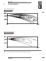
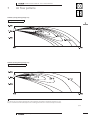
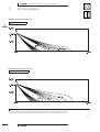
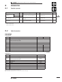
1
technical data
Wall Mounted
Inverter Controlled Unit
Split
Sky Air
air conditioning systems
FTK/FTX(D)-JA/H/J
Split - Sky Air
ISO14001 assures an effective environmental
management system in order to help protect
human health and the environment from the potential
impact of our activities, products and services and to
assist in maintaining and improving the quality of
the environment
Daikin Europe N.V. is approved by LRQA for its Quality
Management System in accordance with the ISO9001
standard. ISO9001 pertains to quality assurance regarding
design, development, manufacturing as well as to services
related to the product.
Daikin units comply with the European
regulations that guarantee the safety of
the product.
Daikin Europe N.V. is participating
in the EUROVENT Certification Programme.
Products are as listed in the EUROVENT
Directory of Certified Products.
Zandvoordestraat 300
B - 8400 Ostend Belgium
Internet: http://www.daikineurope.com
EEDE02-1/1A • 10/2002
Prepared in Belgium by Goekint Graphics
Specifications are subject to change without prior notice
• Wall Mounted Inverter Controlled Unit • R-22 • FTK/FTX-JA/FTX-H/FTXD-J
TABLE OF CONTENTS
FTK/FTX(D)-JA/H/J
1
Features
2
Specifications
2
.................................................................................
3
.......................................................................
Nominal capacity, capacity steps and nominal input
Technical specifications
Electrical specifications
3
Dimensional drawings
.....................................................
6
4
Piping diagrams
..................................................................
8
5
Wiring diagrams
.................................................................
10
6
Sound level
..........................................................................
12
Sound level data
Sound pressure spectrum
7
Air flow patterns
................................................................
17
8
Accessories
..........................................................................
21
Standard accessories
Optional accessories
9
Control systems
..................................................................
22
10
Centre of gravity
................................................................
26
11
Installation
............................................................................
27
For capacity tables, please refer to part II: outdoor units
Note: R-22 cooling only models, which are produced after 01/07/2002, cannot be sold inside countries
that follow the European Regulation n°2037/2000 EE of 29/09/2000.
• Split - Sky Air • Indoor Units
1
• Wall Mounted Inverter Controlled Unit • R-22 • FTK/FTX-JA/FTX-H/FTXD-J
1
2
1
Features
+ Lightweight and compact
+ Extremely quiet in operation both indoors and outdoors
+ A silent button on the remote control lowers the operation sound of the outdoor
unit (RXD-J) by 3dB(A)
+ The movement sensor saves power consumption in unoccupied
rooms (FTK/FTX-JA)
+ A comfortable sleeping mode pledges you a good night’s rest (FTK/FTX-JA)
+ The home leave operation saves energy during absence. (FTXD-J)
+ Automatic air flow director ensures uniform air flow and temperature distribution:
- The indoor units are equipped with a double horizontal flap for air
discharge
- The indoor units FTK/FTX50-60 are equipped with an extra automatic
vertical air flow director
+ Powerful mode can be selected for rapid cooling or heating
+ Air purification filter
- deodorises the air
- helps to prevent bacterial and viral propagation
+ Washable front panel
+ Up to 4 indoor units can be connected to 1 Multi outdoor unit. All indoor units are
individually controllable with remote control and do not need to be installed in the
same room. They operate simultaneously within the same cooling or heating
mode.
+ The remote control has a 24 hour timer
+ The indoor model also has a start/stop button mounted on the front panel
+ Up to 5 indoor units can be operated from a single centralised control
+ Purpose-designed holder provided for your remote control (FTK/FTX)
+ Inverter control
The use of an integrated inverter control ensures maximum comfort and efficiency.
+ Short start-up cycle
Inverter control enables the required room temperature to be achieved quicker
than with non inverter units, in fact, start-up time is reduced by one third.
+ 30% less power consumption
The inverter controller detects changes in room or outdoor conditions and adjusts
the indoor temperature to compensate within seconds. Rapid response reduces
power consumption to 30% lower than that of non-inverter systems.
2 ! 0 0 3 6
Standard
FTK/FTX
q 8
FTX(D)
5 steps
2
FTK/X-JA
FTK
FTXD
7 x 4 6
FTK/X-JA
z
Optional
FTXD
• Split - Sky Air • Indoor Units
• Wall Mounted Inverter Controlled Unit • R-22 • FTK/FTX-JA/FTX-H/FTXD-J
2
Specifications
NOMINAL CAPACITY and NOMINAL INPUT
For indoor units only:
INDOOR UNITS
NOMINAL INPUT
Cooling
FTK25JAV1NB
0.04
FTK35JAV1NB
0.04
FTK25JAV1NB
RK25JV1NB
1.30∼2.50∼3.00
0.43∼0.945∼1.250
FTK35JAV1NB
RK35JV1NB
1.40∼3.54∼3.80
0.47∼1.345∼1.72
FTK25JAV1NB
273
784
185
7.5
FTK35JAV1NB
273
784
185
7.5
38
32
26
54
7.1
5.9
4.6
39
33
27
55
7.4
6
4.7
rpm
rpm
rpm
1,260
1,075
890
1,300
1,100
900
W
1 x 18F-22
1 x 18
mm
2 x 12 x 1.4
mm
mm
mm
J 6.4
J 9.5
J 18.0
kW
For combination indoor units + outdoor units:
INDOOR UNITS
OUTDOOR UNITS
NOMINAL CAPACITY (2-3) Cooling (1)
min.∼nom.∼max.
NOMINAL INPUT
Cooling
min.∼nom.∼max.
kW
kW
TECHNICAL SPECIFICATIONS
INDOOR UNITS
DIMENSIONS
Unit
WEIGHT
COLOUR
SOUND LEVEL
Unit
Unit
Sound pressure (4)
FAN
Sound power (5)
Air flow rate
Speed
HEAT EXCHANGER
AIR FILTER
AIR DIRECTION CONTROL
TEMPERATURE CONTROL
PIPING CONNECTIONS
Type
Qty x model
Qty x motor output
Type
Rows x stages x fin pitch
INSULATION MATERIAL
Heat insulation tape
For outdoor units
Pair application
Multi model application
H
W
D
mm
mm
mm
kg
high
medium
low
dBA
dBA
dBA
dBA
m3/min
m3/min
m3/min
high
medium
low
steps
high
medium
low
liquid
gas
drain
FTK50HV1NB
0.05
FTK60HV1NB
0.06
2
2
FTK50HV1NB
FTK60HV1NB
For capacities and power input in multi model application, see
chapter MK-H
Almond white
FTK50HV1NB
298
1,050
190
12
FTK60HV1NB
298
1,050
190
12
44
39
35
60
12.9
11.2
9.4
46
42
38
62
14
12.1
10.3
1,240
1,120
1,000
1,320
1,180
1,040
5 steps and auto
Cross flow fan
1 x D40A-05 (DC-Motor)
1 x 35
J7 Hi-XA tube
2 x 12 x 1.4
2 x 14 x 1.2
Removable/washable/mildew proof
Right, left, horizontal and downward
Microcomputer control
J 6.4
J 6.4
J 12.7
J 12.7
J 18.0
J 18.0
Both liquid and gas pipes
1 x 18F-22
1 x 18
1 x D40A-05 (DC-Motor)
1 x 35
2 x 14 x 1.2
J 6.4
J 15.9
J 18.0
See chapter RK-J
See chapter MK-H
3D027499B
3D027500B
3D013612B
3D013616B
• Split - Sky Air • Indoor Units
3
• Wall Mounted Inverter Controlled Unit • R-22 • FTK/FTX-JA/FTX-H/FTXD-J
2
2
2
Specifications
NOMINAL CAPACITY and NOMINAL INPUT
For indoor units only:
INDOOR UNITS
NOMINAL INPUT
Cooling
Heating
FTX25JAV1NB
0.04
0.04
FTX35JAV1NB
0.04
0.04
FTXD50JV1B
0.04
0.038
FTXD60JV1B
0.045
0.045
FTXD71JV1B
0.05
0.05
FTX25JAV1NB
RX25JV1NB
1.30∼2.50∼3.00
1.30∼3.40∼4.00
0.35∼0.98∼1.35
0.35∼1.130∼1.350
FTX35JAV1NB
RX35JV1NB
1.40∼3.43∼3.80
1.40∼4.10∼5.10
0.50∼1.43∼1.72
0.405∼1.375∼1.90
FTXD50JV1B
RXD50JV1B
0.90∼5.20∼5.80
0.90∼6.50∼8.00
0.45∼1.73∼2.30
0.45∼1.91∼2.80
FTXD60JV1B
RXD60JV1B
0.90∼6.20∼7.00
0.90∼7.20∼8.50
0.45∼2.21∼2.90
0.45∼2.12∼3.30
FTXD71JV1B
RXD71JV1B
0.90∼7.10∼8.00
0.90∼8.50∼9.50
0.45∼2.63∼3.45
0.45∼2.74∼3.80
mm
mm
mm
kg
FTX25JAV1NB
273
784
185
7.5
FTX35JAV1NB
273
784
185
7.5
FTXD60JV1B
298
1,050
190
12
FTXD71JV1B
298
1,050
190
12
dBA
dBA
dBA
dBA
38/38
32/32
26/26
54/54
39/39
33/33
27/27
55/55
FTXD50JV1B
298
1,050
190
12
Almond white
44/42
40/37
35/32
60/58
45/44
41/39
37/34
61/60
46/46
42/40
37/34
62/62
m3/min
m3/min
m3/min
7.1/8.4
5.9/7.0
4.6/5.7
7.4/8.4
6.0/7.1
4.7/5.9
13.0/16.5
11.5/13.7
9.9/11.1
13.7/17.3
11.8/14.1
9.9/11.1
1,260/1,300
1,075/1,125
890/950
1,300/1,300
1,100/1,130
900/970
1,380/1,380
1,240/1,190
1,100/1,000
1,450/1,450
1,270/1,220
1,100/1,000
1 x 18F-22
1 x 18F-22
W
1 x 18
1 x 18
1 x D54A-31
(DC-Motor)
1 x 54
1 x D54A-31
(DC-Motor)
1 x 54
mm
2 x 12 x 1.4
2 x 12 x 1.4
2 x 14 x 1.2
2 x 14 x 1.2
mm
mm
mm
J 6.4
J 9.5
J 18
J 6.4
J 12.7
J 18
J 6.4
J 15.9
J 18
J 9.5
J 15.9
J 18
kW
kW
For combination indoor units + outdoor units:
INDOOR UNITS
OUTDOOR UNITS
NOMINAL CAPACITY (3-4) Cooling (1)
min.∼nom.∼max.
Heating (2)
min.∼nom.∼max.
NOMINAL INPUT
Cooling
min.∼nom.∼max.
Heating
min.∼nom.∼max.
kW
kW
kW
kW
TECHNICAL SPECIFICATIONS
INDOOR UNITS
DIMENSIONS
WEIGHT
COLOUR
SOUND LEVEL
FAN
HEAT EXCHANGER
AIR FILTER
AIR DIRECTION CONTROL
TEMPERATURE CONTROL
PIPING CONNECTIONS
Unit
Unit
Unit
Sound pressure
(cooling/heating) (5)
H
W
D
high
medium
low
Sound power (Horizontally located scroll type)
(6)
Air flow rate
high
medium
low
Speed
steps
high
medium
low
Type
Qty x model
Qty x motor output
Type
Rows x stages x fin pitch
INSULATION MATERIAL
Heat insulation tape
For outdoor units
Pair application
Multi model application
liquid
gas
drain
rpm
rpm
rpm
12.3/14.9
10.7/12.8
9.1/10.5
5 steps and auto
1,320/1,280
1,170/1,120
1,020/960
Cross flow fan
1 x D54A-31
(DC-Motor)
1 x 54
J7 Hi-XA tube
2 x 14 x 1.2
Removable/washable/mildew proof
Right, left, horizontal and downward
Microcomputer control
J 6.4
J 12.7
J 18
Both liquid and gas pipes
See chapter RX(D)-J
See chapter MX-H
3D027497B
3D027498B
3D029183/4/5
4
• Split - Sky Air • Indoor Units
• Wall Mounted Inverter Controlled Unit • R-22 • FTK/FTX-JA/FTX-H/FTXD-J
2
Specifications
ELECTRICAL SPECIFICATIONS
For indoor units only:
CURRENT
Nominal running current
Maximum running current
cooling
cooling
FTK25JAV1NB
0.18
A
A
For combination indoor units + outdoor units:
CURRENT
Nominal running current
Maximum running current
Starting current
cooling
cooling
cooling
For indoor units only:
POWER SUPPLY
NOMINAL DISTRIBUTION SYSTEM Phase
VOLTAGE
Frequency
Voltage
Maximum running current
cooling
heating
cooling
heating
A
A
A
Hz
V
FTK25JAV1NB
V1
1∼
50
230
A
A
A
A
For combination indoor units + outdoor units:
CURRENT
Nominal running current
Maximum running current
Starting current
For indoor units only:
POWER SUPPLY
NOMINAL DISTRIBUTION SYSTEM Phase
VOLTAGE
Frequency
Voltage
cooling
heating
cooling
heating
cooling
heating
FTK60HV1NB
0.6
FTK25JAV1NB
FTK35JAV1NB
FTK50HV1NB
FTK60HV1NB
RK25JV1NB
RK35JV1NB
4.5
6.3
For capacities and power input in multi model application, see
chapter MK-H
See chapter RK-J: Electrical data
See chapter RK-J: Electrical data
ELECTRICAL SPECIFICATIONS
For indoor units only:
CURRENT
Nominal running current
FTK35JAV1NB
FTK50HV1NB
0.18
0.5
See chapter RK-J: Electrical data
A
A
A
A
A
A
Hz
V
FTX25JAV1NB
0.18
0.18
FTK35JAV1NB
V1
1∼
50
230
FTX35JAV1NB
0.18
0.18
FTK50HV1NB
V1
1∼
50
230
FTXD50JV1B
0.18
0.17
2
2
FTK60HV1NB
V1
1∼
50
230
FTXD60JV1B
0.2
0.2
FTXD71JV1B
0.22
0.22
FTXD60JV1B
RXD60JV1B
9.7
9.3
FTXD71JV1B
RXD71JV1B
11.5
12
See chapter RX(D)-J: Electrical data
FTX25JAV1NB
RX25JV1NB
4.8
5.3
FTX35JAV1NB
RX35JV1NB
6.4
6.2
FTXD50JV1B
RXD50JV1B
7.6
8.4
See chapter RX(D)-J: Electrical data
5.3
5.3
6.4
6.4
FTX25JAV1NB
V1
1∼
50
230
FTX35JAV1NB
V1
1∼
50
230
See chapter RX(D)-J: Electrical data
FTXD50JV1B
V1
1∼
50
230
FTXD60JV1B
V1
1∼
50
230
FTXD71JV1B
V1
1∼
50
230
NOTES
1
Nominal cooling capacities are based on: indoor temperature 27°CDB/19°CWB * outdoor temperature 35°CDB * refrigerant piping length: 7.5m
(horizontal) * level difference: 0m.
2
Capacities are net, including a deduction for cooling for indoor fan motor heat.
3
Units should be selected on nominal capacity. Maximum capacity is limited to peak periods.
4
The sound pressure level is measured via a microphone at a certain distance from the unit. It is a relative value, depending on the distance and
acoustic environment. For measuring conditions: please refer to item 6 of this chapter.
5
The sound power level is an absolute value indicating the ’’power’’ which a sound source generates.
• Split - Sky Air • Indoor Units
5
• Wall Mounted Inverter Controlled Unit • R-22 • FTK/FTX-JA/FTX-H/FTXD-J
3
2
Dimensional drawings
unit (mm)
FTK25-35JA
The mark (Y) shows piping direction
3
Air flow (indoor) required space
(for performance and
maintenance)
Rear
Left
Right
Terminal strip
with earth
terminal
Room temp. thermistor
Intelligent eye sensor
Timer indicator lamp
Operation indicator lamp
Operation switch
Flaps
Note:
Gas pipe specification
Name plate
Signal receiver
Front grille fixing screws
(inside)
(space for
maintenance)
(space for
maintenance)
Intelligent eye sensor
indicator lamp
Bottom
(space for
performance)
(including installation
plate)
FTK25
FTK35
Gas pipe see note (the length of pipe outside
the unit: about 300)
Liquid pipe J6.4 CuT (the length of pipe outside the
unit: about 350)
Signal transmitter
J 9.5Cut
J 12.7Cut
Drain hose (connecting part I.D. J 14.0, O.D.
J 18.0)
(The hose length on the outside of the unit
is approx. 410)
Blade angle
Up/down (automatic)
Cooling
Blow
Dry
Right/left (manual)
Wall hole for embedded piping
J 65 hole
(ARC423A2)
Wall hole J 65 hole
Standard locations of wall holes
Infrared remote control
3D019915-C
unit (mm)
FTK50-60H
Air flow (indoor) required
space (for performance
and maintenance)
The mark (Y) shows piping direction
Rear
Left
Right
(space for
performance)
(space for
maintenance)
(space for maintenance)
(including installation
plate)
Space for drawing air filters
Name plate
Display panel nameplate
Terminal strip
Diffuser
Signal receiver and
operation switch
flap
Under
Under
Front grille fixing screws
Room temp.
thermistor
Cleaning indicator lamp
Timer indicator lamp
Operation indicator lamp
Signal transmitter
Note:
Gas pipe specification
(The length of pipe outside
the unit: about 450)
Gas pipe see note (the length of pipe outside
the unit: about 400)
FTK50
J 12.7CuT
FTK60
J 15.9CuT
Drain hose (connecting part I.D. J 14.0, O.D.
J 18.0)
(The hose length on the outside of the
unit is approx. 490)
Blade angle
Up/down (automatic)
Cooling / dry
Diffuser
Right/left: (automatic)
flap
Wall hole for embedded piping
J 80 hole
Standard locations of wall holes
Infrared remote control
6
Wall hole J 80 hole
• Split - Sky Air • Indoor Units
3D013485
• Wall Mounted Inverter Controlled Unit • R-22 • FTK/FTX-JA/FTX-H/FTXD-J
3
Dimensional drawings
unit (mm)
FTX25-35JA
The mark (Y) shows piping direction
Air flow (indoor) required space
(for performance and
maintenance)
Rear
Left
(space for
maintenance)
Intelligent eye sensor
indicator lamp
(space for
maintenance)
Note:
Gas pipe specification
Name plate
Signal receiver
Flaps
Terminal strip
with earth
terminal
Room temp. thermistor
Intelligent eye sensor
Front grille fixing screws
(inside)
FTX25
FTX35
Gas pipe see note (the length of pipe outside
the unit: about 300)
Timer indicator lamp
Operation indicator lamp
J 9.5Cut
J 12.7Cut
Drain hose (connecting part I.D. J 14.0,
O.D. J 18.0)
(The hose length on the outside of the unit
is approx. 410)
Liquid pipe J6.4 CuT (the length of pipe outside the
unit: about 350)
Operation switch
Signal transmitter
3
(space for
performance)
(including installation
plate)
Right
Bottom
2
Blade angle
Up/down (automatic)
Cooling
Heating
Dry
Wall hole for embedded piping
J 65 hole
Right/left (manual)
(ARC423A1)
Wall hole J 65 hole
Standard locations of wall holes
Infrared remote control
3D019914D
unit (mm)
FTXD50∼71J
Air flow (indoor) required
space (for performance
and maintenance)
The mark (Y) shows piping direction
Rear
Rear
(space for performance)
Left
Right
(space for
maintenance)
(space for maintenance)
(including installation
plate)
Terminal strip
with earth
terminal
Name plate
Space for drawing air filters
Diffuser
Signal receiver and
operation switch
flap
Under
Home leave lamp
Under
Room temp.
thermistor
Timer indicator lamp
Front grille fixing screws
Operation indicator lamp
Blade angle
Signal transmitter
Up/down (automatic)
Cooling
Dry
Gas pipe JA Cut
(The length of pipe outside the unit:
about 400)
Liquid pipe J 6.4CuT (the length
of pipe outside the unit: about
450)
Note:
Gas pipe specification
A
B
FTXD50
12.7
6.4
FTXD60
15.9
6.4
FTXD71
15.9
9.5
Drain hose (connecting part I.D. J 14.0, O.D.
J 18.0)
(The hose length on the outside of the
unit is approx. 490)
Heating
Diffuser
flap
Right/left:
(automatic)
(ARC417A14)
Wall hole for embedded piping
J 80 hole
Wall hole J 65 hole
Standard locations of wall holes
Infrared remote control
• Split - Sky Air • Indoor Units
3D024823B
7
• Wall Mounted Inverter Controlled Unit • R-22 • FTK/FTX-JA/FTX-H/FTXD-J
4
2
4
Piping diagrams
FTK25-35JA
FTX25-35JA
Indoor unit
Heat exchanger
Thermistor on heat
exchanger
Cross flow fan
Field piping
Fan motor
Field piping
A
FTK25FTX25FTK35FTX35-
9.5
12.7
4D019960D
FTK50-60H
Indoor unit
Heat exchanger
Note:
1. Gas pipe specification
A
FTK50
FTK60
12.7
15.9
Cross flow fan
Field piping
Fan motor
Field piping
(A CuT)
Refrigerant flow
→ : Cooling
8
• Split - Sky Air • Indoor Units
4D013572
• Wall Mounted Inverter Controlled Unit • R-22 • FTK/FTX-JA/FTX-H/FTXD-J
4
Piping diagrams
FTXD50∼71J
2
Indoor unit
4
Thermistor on inlet pipe
Heat exchanger
Thermistor on heat
exchanger
Field piping
Note:
1. Gas pipe specification
FTXD50
FTXD60
FTXD71
Field piping
A
B
12.7
15.9
15.9
6.4
6.4
9.5
Cross flow fan
Fan motor
Refrigerant flow
Cooling
Heating
• Split - Sky Air • Indoor Units
4D024820A
9
• Wall Mounted Inverter Controlled Unit • R-22 • FTK/FTX-JA/FTX-H/FTXD-J
5
2
Wiring diagrams
FTK25-35JA
5
Intelligent eye
sensor
(Terminal for centralised control)
Outdoor
g
Field wiring
Caution
Note that operation will restart automatically if
the main power supply is turned off and then
back on again.
Signal
receiver
R
Indoor
Infrared remote
control
Protective earth
Running capacitor
Fuse
Pilot lamp
Fan motor
Swing motor
Printed circuit board
Thermistor
Connector
Operation switch (SW7)
Terminal strip
C70
FU
H1P∼H3P
M1F
M1S
PCB1∼PCB3
R1T,R2T
S1∼S36
S1W
X1M
3D020027F
FTK50-60H
Outdoor
g
Field wiring
R
FG
FU
H1∼H3
H1P∼H3P
M1F
M1S, M2S
PCB1∼PCB4
R1T,R2T
S1∼S37
S1W
S2W
S8W
X1M
Signal
receiver
Infrared remote
control
Protective earth
Frame ground
Fuse
Harness
Pilot lamp
Fan motor
Swing motor
Printed circuit board
Thermistor
Connector
Operation switch
Operation switch
Cleaning indicator reset switch
Terminal strip
Indoor
3D013000-1
10
• Split - Sky Air • Indoor Units
• Wall Mounted Inverter Controlled Unit • R-22 • FTK/FTX-JA/FTX-H/FTXD-J
5
Wiring diagrams
2
FTX25-35JA
5
Intelligent eye
sensor
Outdoor
(Terminal for centralised control)
g
Field wiring
Caution
Note that operation will restart
automatically if the main power supply is
turned off and then back on again.
Signal receiver
Indoor
Infrared remote
control
R
C70
FU
H1P∼H3P
M1F
M1S
PCB1∼PCB3
R1T,R3T
S1∼S36
S1W
X1M
Protective earth
Running capacitor
Fuse
Pilot lamp
Fan motor
Swing motor
Printed circuit board
Thermistor
Connector
Operation switch (SW7)
Terminal strip
3D020026F
FTXD50∼71J
Outdoor
g
Field wiring
Caution
Note that operation will restart
automatically if the main power supply is
turned off and then back on again.
R
Signal receiver
Infrared remote
control
Indoor
FG
FU
H1∼H3
H1P∼H3P
M1F
M1S, M2S
PCB1∼PCB4
R1T,R3T
S1∼S201
S1W
X1M
Protective earth
Frame ground
Fuse
Harness
Pilot lamp
Fan motor
Swing motor
Printed circuit board
Thermistor
Connector
Operation switch
Terminal strip
3D025027
• Split - Sky Air • Indoor Units
11
• Wall Mounted Inverter Controlled Unit • R-22 • FTK/FTX-JA/FTX-H/FTXD-J
6
6-1
2
Sound level data
Cooling only
Sound pressure level
6
6-1
Sound level
230V
Model
50Hz
Measuring location
H
L
FTK25JAV1NB
38
26
FTK35JAV1NB
39
27
FTK50HV1NB
44
35
FTK60HV1NB
46
38
Location of microphone
Sound power level (H)
54
55
Indoor unit
60
Center
62
Heating only
Sound pressure level
230V
Model
12
50Hz
H
(cooling/heating)
L
(cooling/heating)
FTX25JAV1NB
38/38
26/26
FTX35JAV1NB
39/39
27/27
FTXD50JV1B
44/42
35/32
FTXD60JV1B
45/44
37/34
FTXD71JV1B
46/46
37/34
• Split - Sky Air • Indoor Units
Measuring location
Sound power level (H)
(cooling/heating)
Location of microphone
54/54
55/55
60/58
Indoor unit
61/60
Center
62/62
• Wall Mounted Inverter Controlled Unit • R-22 • FTK/FTX-JA/FTX-H/FTXD-J
6
6-2
Sound level
Sound pressure spectrum
Cooling only
FTK25JAV1NB
2
FTK35JAV1NB
6
Octave band sound pressure level
dB:(0dB = 0.0002 µ bar)
Octave band sound pressure level
dB:(0dB = 0.0002 µ bar)
6-2
approximate threshold
hearing for continuous
noise
approximate threshold
hearing for continuous
noise
4D025038A
4D025039A
Octave band center frequency (Hz)
Octave band center frequency (Hz)
FTK60HV1NB
Octave band sound pressure level
dB:(0dB = 0.0002 µ bar)
Octave band sound pressure level
dB:(0dB = 0.0002 µ bar)
FTK50HV1NB
approximate threshold
hearing for continuous
noise
approximate threshold
hearing for continuous
noise
4D013510
4D013512
Octave band center frequency (Hz)
Octave band center frequency (Hz)
Legend
50Hz 230V(H)
50Hz 230V(L)
Notes
1. Operation sound is measured in an anechoic chamber.
2. Operation sound level differs with operation and ambient conditions.
• Split - Sky Air • Indoor Units
13
• Wall Mounted Inverter Controlled Unit • R-22 • FTK/FTX-JA/FTX-H/FTXD-J
6
6-2
2
Sound level
Sound pressure spectrum
FTX25JAV1NB (Heating)
FTX25JAV1NB (Cooling)
6
Octave band sound pressure level
dB:(0dB = 0.0002 µ bar)
Octave band sound pressure level
dB:(0dB = 0.0002 µ bar)
6-2
approximate threshold
hearing for continuous
noise
3D025037A
approximate threshold
hearing for continuous
noise
3D025037A
Octave band center frequency (Hz)
FTX35JAV1NB (Cooling)
Octave band center frequency (Hz)
Octave band sound pressure level
dB:(0dB = 0.0002 µ bar)
Octave band sound pressure level
dB:(0dB = 0.0002 µ bar)
FTX35JAV1NB (Heating)
approximate threshold
hearing for continuous
noise
3D025036A
approximate threshold
hearing for continuous
noise
3D025036A
Octave band center frequency (Hz)
Octave band center frequency (Hz)
Legend
50Hz 230V(H)
50Hz 230V(L)
14
• Split - Sky Air • Indoor Units
Notes
1. Operation sound is measured in an anechoic chamber.
2. Operation sound level differs with operation and ambient conditions.
• Wall Mounted Inverter Controlled Unit • R-22 • FTK/FTX-JA/FTX-H/FTXD-J
6
6-2
Sound level
Sound pressure spectrum
FTXD50JV1B (Heating)
FTXD50JV1B (Cooling)
2
6
Octave band sound pressure level
dB:(0dB = 0.0002 µ bar)
Octave band sound pressure level
dB:(0dB = 0.0002 µ bar)
6-2
approximate threshold
hearing for continuous
noise
approximate threshold
hearing for continuous
noise
3D029236
3D029236
Octave band center frequency (Hz)
FTXD60JV1B (Cooling)
Octave band center frequency (Hz)
Octave band sound pressure level
dB:(0dB = 0.0002 µ bar)
Octave band sound pressure level
dB:(0dB = 0.0002 µ bar)
FTXD60JV1B (Heating)
approximate threshold
hearing for continuous
noise
3D027662A
approximate threshold
hearing for continuous
noise
3D027662A
Octave band center frequency (Hz)
Octave band center frequency (Hz)
Legend
50Hz 230V(H)
50Hz 230V(L)
Notes
1. Operation sound is measured in an anechoic chamber.
2. Operation sound level differs with operation and ambient conditions.
• Split - Sky Air • Indoor Units
15
• Wall Mounted Inverter Controlled Unit • R-22 • FTK/FTX-JA/FTX-H/FTXD-J
6
6-2
2
Sound level
Sound pressure spectrum
FTXD71JV1B (Heating)
FTXD71JV1B (Cooling)
6
Octave band sound pressure level
dB:(0dB = 0.0002 µ bar)
Octave band sound pressure level
dB:(0dB = 0.0002 µ bar)
6-2
approximate threshold
hearing for continuous
noise
approximate threshold
hearing for continuous
noise
3D027663A
3D027663A
Octave band center frequency (Hz)
Octave band center frequency (Hz)
Legend
50Hz 230V(H)
50Hz 230V(L)
Notes
1. Operation sound is measured in an anechoic chamber.
2. Operation sound level differs with operation and ambient conditions.
16
• Split - Sky Air • Indoor Units
• Wall Mounted Inverter Controlled Unit • R-22 • FTK/FTX-JA/FTX-H/FTXD-J
7
Air flow patterns
FTX35JA (Cooling Discharge Angle: 0°)
2
Cooling - air velocity distribution
7
FTX35JA (Heating Discharge Angle: 0°)
Cooling - air temperature distribution
NOTES
To make the air current analysis graphical, the results calculated in the axial flow characteristic equation are used.
Keep in mind that the actual results depend on the insulating performance of a house and the layout of furniture.
Q0150
• Split - Sky Air • Indoor Units
17
• Wall Mounted Inverter Controlled Unit • R-22 • FTK/FTX-JA/FTX-H/FTXD-J
7
2
Air flow patterns
FTX35JA (Cooling Discharge Angle: 45°)
Cooling - air velocity distribution
7
FTX35JA (Heating Discharge Angle: 45°)
Cooling - air temperature distribution
NOTES
To make the air current analysis graphical, the results calculated in the axial flow characteristic equation are used.
Keep in mind that the actual results depend on the insulating performance of a house and the layout of furniture.
Q0151
18
• Split - Sky Air • Indoor Units
• Wall Mounted Inverter Controlled Unit • R-22 • FTK/FTX-JA/FTX-H/FTXD-J
7
Air flow patterns
FTXD60J (Cooling Discharge Angle: 15°)
2
Cooling - air velocity distribution
7
FTXD60J (Heating Discharge Angle: 15°)
Cooling - air temperature distribution
NOTES
To make the air current analysis graphical, the results calculated in the axial flow characteristic equation are used.
Keep in mind that the actual results depend on the insulating performance of a house and the layout of furniture.
Q0152
• Split - Sky Air • Indoor Units
19
• Wall Mounted Inverter Controlled Unit • R-22 • FTK/FTX-JA/FTX-H/FTXD-J
7
2
Air flow patterns
FTXD60J (Cooling Discharge Angle: 40°)
Cooling - air velocity distribution
7
FTXD60J (Heating Discharge Angle: 40°)
Cooling - air temperature distribution
NOTES
To make the air current analysis graphical, the results calculated in the axial flow characteristic equation are used.
Keep in mind that the actual results depend on the insulating performance of a house and the layout of furniture.
Q0153
20
• Split - Sky Air • Indoor Units
• Wall Mounted Inverter Controlled Unit • R-22 • FTK/FTX-JA/FTX-H/FTXD-J
8
8-1
Accessories
Standard accessories
j
A Mounting plate
1
j
B Mounting plate fixing screw
M4 x 25L
25/35 class
6
50/60 class
10
j
E Remote control holder z1
1
j
J Insulation tape (25/35 class only)
1
j
F Fixing screw for remote control holder M3 x 20L
2
j
K Operation manual
1
j
C Air purification filter
2
j
G AAA dry-cell
batteries
2
j
L Installation manual
1
j
D Remote control
1
j
H Indoor unit fixing screw M4x12
2
j
H Drain socket
(heat pump models only)
1
2
8
8-1
z1 Remote control holder is available as standard accessory from serial no.
9900111 (FTK50HV1NB)
9900101 (FTK60HV1NB)
8-2
Optional accessories
FTK25-35JAV1NB
FTX25-35JAV1NB
FTK50-60HV1NB
Option name
FTK/FTX25-35JA
FTK50-60H
1
Centralised control board-up to 5 rooms z1
2
Wiring adaptor for time clock/remote control z2
(normal open pulse contact/normal open contact)
KRP413A1S
3
Air purification filter with frame
KAF918A41
4
Air purification filter without frame
5
Anti-theft protection for remote control
KKF917A4
KKF910A4
6
Central remote control
DCS302B51
−
7
Unified ON/OFF control
DCS301B51
−
8
Schedule timer
DST301B51
−
9
Interface adapter for room air conditioners
KRP928A2S
−
KRC72
KAF918A42
3D020515B
3D013670
FTXD50-60-71J
Option name
Kit name
1
Centralised control board-up to 5 rooms z1
2
Wiring adaptor for time clock/remote control z2
(normal open pulse contact/normal open contact)
KRP413A1S
3
Central remote control
DCS302B51
4
Unified ON/OFF control
DCS301B51
5
Schedule timer
DST301B51
6
Interface adapter for room air conditioners
KRP928A2S
7
Air purification filter with frame
KAF918A41
8
Air purification filter without frame
KAF918A42
9
Anti-theft protection for remote control
KKF910A4
KRC72
z1 Wiring adapter is also required for each indoor unit.
z2 Wiring adapter supplied by Daikin. Time clock and other devices: field supply.
• Split - Sky Air • Indoor Units
21
• Wall Mounted Inverter Controlled Unit • R-22 • FTK/FTX-JA/FTX-H/FTXD-J
9
9-1
2
Control systems
Infrared remote control
FTK25-35JAV1NB
9
9-1
Transmitter
Display
It displays the current
settings. (In this illustration,
each section is shown with
all its displays ON for the
purpose of explanation.
Some models may not
show all its indications.)
Open the
cover
Sends signals to the indoor unit.
TEMPERATURE/TIME adjustment
buttons
Change the temperature or time setting.
POWERFUL button
On/Off button
Press it once to start operation. To stop it, press it
once again.
MODE selector button
Selects the operation mode.
FAN setting button
FTK I: Dry programme
u:
B:
Selects the air flow rate setting.
Cool
SWING button
Fan
Good Sleep Cooling Operation (G-sleep)
Intelligent Eye button
Cancels the timer setting
ON TIMER button
TIMER CANCEL button
OFF TIMER button
ARC423A1
ON TIMER setting button
It changes the time setting
22
• Split - Sky Air • Indoor Units
CLOCK button
• Wall Mounted Inverter Controlled Unit • R-22 • FTK/FTX-JA/FTX-H/FTXD-J
9
9-1
Control systems
Infrared remote control
FTK50-60HV1NB
2
Transmitter
Sends signals to the indoor unit.
On/Off button
9
9-1
Press it once to start operation.
To stop it, press it once again.
Display
Display the current
settings. (In this
illustration, each section is
shown with all its
displays ON for the
purpose of explanation.)
Open the
cover
OFF TIMER button
TEMPERATURE/TIME
adjustment buttons
Change the temperature or time setting.
CLOCK button
ON TIMER button
MODE selector button
Selects the operation mode.
FTK I: Dry programme u: Cool
B:
TIMER CANCEL button
Cancels the timer setting
Fan
SWING button
FAN setting button
Selects the air flow rate setting.
Powerful mode button
• Split - Sky Air • Indoor Units
23
• Wall Mounted Inverter Controlled Unit • R-22 • FTK/FTX-JA/FTX-H/FTXD-J
9
9-1
2
Control systems
Infrared remote control
FTX25-35JAV1NB
9
9-1
Transmitter
Display
It displays the current
settings. (In this illustration,
each section is shown with
all its displays ON for the
purpose of explanation.
Some models may not
show all its indications.)
Open the
cover
Sends signals to the indoor unit.
TEMPERATURE/TIME adjustment
buttons
Change the temperature or time setting.
POWERFUL button
On/Off button
Press it once to start operation. To stop it, press it
once again.
MODE selector button
Selects the operation mode.
FAN setting button
FTX ,: Auto
I:
u:
w:
Selects the air flow rate setting.
Dry
Cool
SWING button
Heat
Good Sleep Cooling Operation (G-sleep)
Intelligent Eye button
Cancels the timer setting
ON TIMER button
TIMER CANCEL button
OFF TIMER button
ON TIMER setting button
It changes the time setting
24
• Split - Sky Air • Indoor Units
ARC423A2
CLOCK button
• Wall Mounted Inverter Controlled Unit • R-22 • FTK/FTX-JA/FTX-H/FTXD-J
9
9-1
Control systems
Infrared remote control
2
FTXD50,60,71JV1B
9
9-1
Open the
cover
Transmitter
It sends signals to the indoor unit.
On/Off button
Press it once to start
operation. To stop it, press it once
again.
Display
It displays the current settings. (In this
illustration, each section is shown
with all its displays ON for the
purpose of explanation.)
TEMPERATURE/TIME adjustment buttons
It change the temperature or time setting.
CLOCK button
OFF TIMER button
TIMER CANCEL button
ON TIMER button
It cancels the timer setting.
FAN setting button
It selects the air flow rate setting.
SWING button
MODE selector button
OUTDOOR UNIT SILENT
button
POWERFUL button
HOME LEAVE button
<ARC417 A14>
• Split - Sky Air • Indoor Units
25
• Wall Mounted Inverter Controlled Unit • R-22 • FTK/FTX-JA/FTX-H/FTXD-J
10
Centre of gravity
2
10
FTK25-35JAV1NB
FTX25-35JAV1NB
4D020686D
FTXD50-60-71JV1B
4D027652
26
• Split - Sky Air • Indoor Units
• Wall Mounted Inverter Controlled Unit • R-22 • FTK/FTX-JA/FTX-H/FTXD-J
11
Installation
2
Indoor/outdoor unit installation drawings
11
How to attach the indoor unit.
Hook the claws of the bottom frame to the
mounting plate.
If the claws are difficult to hook, remove the
front panel.
Mounting plate
How to remove the indoor unit.
Push up the marked area (at the lower part of
the front panel) to release the claws. If it is
difficult to release, remove the front panel.
j
A Mounting plate
Clip
Bottom frame
Front panel
Mark (rear side)
j
B M4 x 25L
The mounting plate should be
installed on a wall which can
support the weight of the indoor
unit.
Cut thermal insulation pipe to
an appropriate length and
wrap it with tape, making sure
that no gap is left in the
insulation pipe’s cut line.
30mm or more from ceiling
Front grille
Wrap the installation pipe with the
finishing tape from bottom to top
50 mm or more from walls
(on both side)
Caulk pipe hole
gap with putty.
Air filters
Model
Max. allowable length
Max. allowable height
Additional refrigerant required for
refrigerant pipe exceeding 10 m in
length.
Gas pipe
Liquid pipe
Service lid
This service lid is an open/close type.
+ Remove the screws on the service lid.
+ Slide the service lid leftward.
+ Rotate the service lid upward.
25 class
Cooling only: 25m
15m
35 class
60 class
See the installation manual supplied
with the Multi outdoor unit.
20 g/m
O.D. 9.5 mm
50 class
O.D. 12.7 mm O.D. 15.9 mm
O.D. 6.4 mm
O.D. 15.9 mm
* Be sure to add the proper amount of additional refrigerant. Failure to do
so may result in reduced performance.
With a Multi indoor unit, install as described in the installation manual
supplied with the Multi outdoor unit.
j
C Air purification filters
Install air purification filter on air
filter
Air filter
Air purification filters
250 mm from wall
Service lid
j
2 Push
j
D Infrared remote
control
j
1 Insert
How to remove the service lid.
+ This service lid is an open/close type.
+ Slide the lid downward to remove it.
How to attach the service lid.
+ Insert the upper part of the service lid into the
outdoor unit to install.
+ Tighten the screws.
Before screwing the remote
control holder to the wall,
make sure that control
signals are properly received
by indoor unit.
j
E Remote control holder
j
F (M3 x 20L)
Foot bolt-hole
centres
In sites with poor drainage, use block bases for
outdoor unit. Adjust foot height until the unit is
leveled. Otherwise, water leakage or pooling of
water may occur.
Foot bolt-hole
centres
From unit’s side
• Split - Sky Air • Indoor Units
Allow space for piping and electrical
servicing.
Where there is a danger of the unit falling, use
foot bolts, or wires.
27