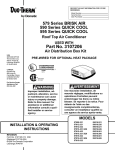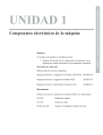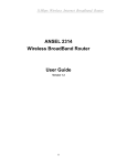
1
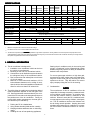
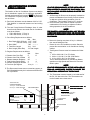
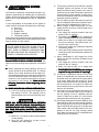
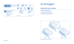
RECORD THIS UNIT INFORMATION FOR FUTURE REFERENCE:
®
Model Number
Serial Number
Date Purchased
600 Series Penguin
579 Series BRISK AIR
590 Series QUICK COOL
595 Series QUICK COOL
Roof Top Air Conditioner
USED WITH
USA
SERVICE OFFICE
The Dometic Corp.
509 So. Poplar St.
LaGrange, IN 46761
CANADA
Dometic Dist.
866 Langs Dr.
Cambridge, Ontario
CANADA N3H 2N7
Part No. 3106481.009
Electronic Kit Control
THIS UNIT IS DESIGNED FOR OEM INSTALLATION
ALL INITIAL INSTALLATIONS MUST BE APPROVED BY THE SALES DEPT.
®
®
CERTIFIED
LR23565
637G
WARNING
AVER
TISSEMENT
VERTISSEMENT
Improper installation, adjustment, alteration, service
or maintenance can cause
injury or property damage.
Refer to this manual. For
assistance or additional
information consult a qualified installer or service
agency.
Une mauvaise installation, de
mauvais réglages, modifications ou
opérations d’entretien peuvent
endommager les biens ou même
blesser. Se reporter à la notice. Pour
obtenir de l’aide ou des
reseignements complémentaires,
consulter un installateur qualifié ou
une agence de service après-vente.
MODELS
INST
ALLA
TION & OPERA
TING
INSTALLA
ALLATION
OPERATING
INSTRUCTIONS
Form No. 3106500.006 3/95
©1995 The Dometic Corp.
LaGrange, IN 46761
1
57908.521
57912.621
57915.421
57915.426
57915.521
57915.526
57915.621
57915.626
59016.521
59016.526
59016.621
59016.626
59516.501
59516.506
59516.601
59516.606
600312.321
600312.421
600315.321
600315.421
SPECIFICATIONS
59516.501
59516.506
59516.601
59516.606
600312.321 600312.421 600315.321
600315.421
13,500
MODEL NO.
57908.521 57912.621
57915.421 57915.521
57915.426 57915.526
57915.621
57915.626
59016.521
59016.526
59016.621
59016.626
Nominal Capacity (BTU/HR) *
7,100
13,500
13,500
15,000
15,000
11,000
11,000
13,500
11,000
Electrical Rating
13,500
115 VAC, 60 Hz., 1 ph.
Compressor Rated Load Amps
6.6
8.5
11.5
12.1
11.0
12.9
12.9
9.5
10.7
12.4
11.5
Fan Motor Rated Load Amps
2.5
2.5
2.5
2.5
2.5
2.5
2.5
3.1
3.1
3.1
3.1
Compressor Locked Rotor Amps
34.0
48.3
50.0
59.0
54.4
71.0
71.0
53.0
50.0
60.0
50.0
Fan Motor Locked Rotor Amps
5.8
5.8
5.8
5.8
5.8
6.0
6.0
8.8
8.8
8.8
8.8
Heater Amps/Watts @ 120VAC
NOT AVAILABLE ON THESE MODELS
12.7/1530
325 / 250
350/250
SCFM-High Speed Max./Min.
Total Static - Min/Max.
0.55 / 0.90" W.C.
Refrigerant R22 Charge ( Oz.)
17.0
16.0
13.5
Minimum Wire Size **
16.0
26.5
31.0
0.12/0.65" W.C.
16.5
16.0
15.5
101
96
17.0
12 AWG Copper Up to 24 ft.
20 Amp Time Delay Fuse or 20 Amp HACR Circuit Breaker
DC Circuit Protection
Installation must comply with all National, State, Providence, and/or local Electrical Codes
Installed Weight (Pounds)
Size ***
335/250
0.40/1.10
16.0
AC Circuit Protection
Minimum Generator
NOT AVAILABLE
75
1 Unit
2 Units
94
100
94
94
101
102
95
102
2.5 KW
3.5 KW
2.5 KW
3.5 KW
4.0 KW
5.0 KW
4.0 KW
5.0 KW
*
Maximum unit performance achieved at full rated voltage.
**
For distances over 24 ft. consult the National Electrical Code.
*** The Dometic Corporation gives GENERAL guidelines for generator requirements. These guidelines come from experiences people have had in
actual applications. When sizing the generator, the total power usage of your recreational vehicle must be considered. Also keep in mind generators
lose power at high altitudes and from lack of maintenance.
1. GENERAL INFORMATION
Starting the air conditioner early in the morning and
giving it a "head start" on the expected high outdoor
ambient will greatly improve its ability to maintain the
desired indoor temperature.
A. This air conditioner is designed for:
1. Installation on a recreational vehicle at the time
the vehicle is manufactured.
2. Mounting on the roof of a recreational vehicle.
3. Connection to an air distribution system located in
the ceiling/roof cavity of the recreational vehicle.
4. Roof construction with rafters/joists on minimum
of 16 inch centers.
5. Minimum of 2.00 inches and maximum of 5.50
inches distance between roof to ceiling of recreational vehicle. Alternate installation methods will
allow for roofs more than 5.50 inches thick.
For a more permanent solution to a high heat gain,
accessories like A&E outdoor patio and window awnings will reduce heat gain by removing the direct
exposure to the sun. They also add a nice area to
enjoy company during the cool of the evening.
C. Condensation
NOTE
B. The ability of the air conditioner to maintain the desired
inside temperature depends on the heat gain of the
RV. Some preventative measures taken by the occupants of the RV can reduce the heat gain and improve
the performance of the air conditioner. During extremely high outdoor temperatures, the heat gain of
the vehicle may be reduced by:
The manufacturer of this air conditioner will not be
responsible for damage caused by condensed moisture on ceilings or other surfaces. Air contains moisture and this moisture tends to condense on cold
surfaces. When air enters the RV, condensed moisture may appear on the ceiling, windows, metal parts,
etc. The air conditioner removes this moisture from
the air during normal operation. Keeping doors and
windows closed when this air conditioner is in operation will minimize condensed moisture on cold surfaces.
1. Parking the RV in a shaded area
2. Using window shades (blinds and/or curtains)
3. Keeping windows and doors shut or minimizing
usage
4. Avoiding the use of heat producing appliances
2
b. The possible fan speeds are LOW, MED, HIGH
and AUTO
AUTO.
c. The temperature Setpoint range is 40 to 99
degrees Fahrenheit.
d. In the case of multiple zones, the zone will
indicate ZONE 1
1, 2, 3 or 4.
2. PRECAUTIONS
WARNING
IMPROPER INSTALLATION MAY DAMAGE EQUIPMENT, COULD ENDANGER LIFE, CAUSE SERIOUS
INJURY AND/OR PROPERTY DAMAGE.
A. Read Installation and Operating Instructions carefully
before attempting to start your air conditioner.
B. The Dometic Corporation will not be liable for any
damages or injury incurred due to failure in following
these instructions.
C. Installation must comply with the National Electrical
Code and any State or Local Codes or regulations.
D. DO NOT add any devices or accessories to this air
conditioner except those specifically authorized by
Dometic.
E. This equipment must be serviced by qualified personnel and some states require these people to be
2) The mode of operation is selected by momentarily
depressing the MODE pushbutton.
3) The fan speed is selected by momentarily depressing the FAN pushbutton.
4) The temperature Setpoint is adjusted by momentarily depressing the up or down arrow.
5) An ON/OFF switch is provided on the lower right
edge of the Comfort Control Center
Center.
licensed.
6) In the event that a Remote Temperature Sensor
(Part No.
) is not used, the Comfort Control
Center temperature sensor is used. In this case,
the Comfort Control Center must be treated as
a wall thermostat and appropriately mounted in
the RV.
3. CONTROL DESCRIPTION
The Dometic Air Conditioner Control is a sophisticated
electronic control using the latest electronic technology.
It consists of a Comfort Control Center (Part No.
3106363.007) and an Electronic Control Box (Part
No. 3106481.009
3106481.009). The Comfort Control Center is the
operator interface. It contains a liquid crystal display
(LCD) and the operator switches and buttons. The
Electronic Control Box contains the interface circuitry
for the air conditioner.
7) The Comfort Control Center is connected to the
Electronic Control Box via a 4-conductor telephone cable using telephone RJ-11 connectors.
B. ELECTRONIC CONTROL BOX
1) The Electronic Control Box contains relays for
switching the various fan speeds, compressor and
furnace.
2) There are wires protruding from the Box for connection to DC power, furnace thermostat wires
and an Energy Management System.
3) A Freeze Control Sensor connects to the Electronic Control Box to allow for the prevention of
freezing coils. This sensor lead is inserted into the
Box and plugged into a connector for that purpose.
4) A Remote Temperature Sensor may be connected to the Electronic Control Box using the
Remote Sensor Kit (Part No. 3106486.008).
4. OPERA
TING INSTR
UCTIONS
OPERATING
INSTRUCTIONS
A. FAN ONLY MODE OPERATION
A. COMFORT CONTROL CENTER
1) Place the Power switch to the ON position.
1) The LCD indicates the mode of operation, the
temperature Setpoint and the fan speed.
a. The possible modes of operation are OFF, FAN
ONLY, COOL, FURNACE and HEAT STRIP
STRIP.
2) Momentarily depress the MODE pushbutton until
FAN ONLY indicator on the Liquid Crystal Display
(LCD) is illuminated.
3
3) Momentarily depress the FAN pushbutton until
LOW, MED,
the desired fan speed indicator (LOW,
HIGH, AUTO
AUTO) is illuminated.
4) The fan will operate in LOW, MED or AUTO
AUTO. HIGH
HEAT
STRIP
speed is not selectable in the
mode.
The fan speed selected while in AUTO is LOW
LOW.
E. SPECIAL CONTROL FEATURES
4) After 5 seconds the selected fan speed will come
on.
1) AUTO FAN: When selected, fan will:
a. If in COOL mode, automatically select the fan
speed depending upon the difference between
the temperature Setpoint and the room temperature.
For a temperarure difference of:
8 deg. or more
- Fan operates on HIGH
4 to 8 deg.
- Fan operates on MED
4 deg. or below
- Fan operates on LOW
b. If in HEAT STRIP mode, automatically select
LOW fan speed.
c. If in FAN ONLY mode, automatically select
LOW fan speed.
B. COOLING MODE OPERATION
1) Momentarily depress the MODE pushbutton until
the COOL indicator on the LCD is illuminated.
2) Momentarily depress the UP or DOWN pushbutton
until the desired temperature Setpoint is displayed.
3) The compressor will come on after a delay of
approximately 2 minutes.
4) The compressor will cycle OFF per the temperature Setpoint displayed. The compressor will restart in approximately two minutes after the control senses the need for cooling. The fan will:
a) Continue to operate in the single selected fan
speed if the AUTO fan speed is not selected.
b) Cycle OFF and ON with the compressor if the
AUTO fan speed is selected.
C.
2) REFRIGERANT COMPRESSOR TIME DELAY:
The compressor will always have a delay in
starting of approximately two minutes any time
it is required to begin the cooling cycle.
3) POWER INTERRUPTION
In the event that power to the air conditioner or
control is interrupted, the system will restart in
the condition previously set by the user.
FURNACE MODE OPERATION
(If so equipped)
1) Momentarily depress the MODE pushbutton until
the FURNACE indicator on the LCD is illuminated.
4) ZONE CONTROL
In the event of a multiple zone installation, the
MODE of operation for each zone may be
independently set. If there are multiple zones,
the LCD indicators ZONE and 1,2,3 or 4 will be
illuminated. To change from one zone to another, simultaneously depress the FAN and
MODE pushbuttons. The indicator will change
the zone data displayed. To program each zone,
simply repeat the programming steps above in
each zone. Note, however, that the system will
prevent operating HEAT and COOL at the same
time.
2) Momentarily depress the UP or DOWN pushbutton
until the desired temperature Setpoint is displayed.
3) The furnace will cycle ON and OFF to provide the
selected temperature.
4) The A/C fan will not operate in the FURNACE
mode.
D. HEAT STRIP MODE OPERATION
(If so equipped)
1) Momentarily depress the MODE pushbutton until
the HEAT STRIP indicator on the LCD is illuminated.
5. MAINTENANCE
2) Momentarily depress the UP or DOWN pushbutton
until the desired temperature Setpoint is displayed.
AIR FILTER
FILTER: Periodically remove the return air filter. Wash
the filter with soap and warm water; let dry and then
reinstall or replace as required.
NOTE: Never run the air conditioner without return air
filter in place. This may plug the unit evaporator coil
with dirt and may substantially affect the performance
of the unit.
3) The electric heat strip will cycle ON and OFF per
the temperature Setpoint displayed. The fan will:
a. Continue to operate in the selected fan speed if
the AUTO fan speed is not selected.
b. Cycle OFF and ON with the heat strip if the
AUTO fan speed is selected.
4
E. After the above checks, call your local service center
for further help. This unit must be serviced by qualified
service personnel only.
6. SERVICE - Unit Does Not Operate
If your unit fails to operate or operates improperly, check
the following before calling your service center.
A. If your RV is connected to motor generator, check to
be sure motor generator is running and producing
power.
B. If RV is connected to power supply by a land line,
check to be sure line is sized properly to run air
conditioner load and it is plugged into power supply.
C. Check your 115 VAC fuse or circuit breaker to see if it
is open.
D. Check your 12 VDC Fuse or Circuit Breaker to see if
it is open.
When calling for service, always give the following:
a. Air Conditioner Model Number and Serial Number
found on Rating Plate located on Base Pan of Air
Conditioner.
b. Electronic Control Kit Part Number and Serial Number found on Rating Plate located on side of Kit.
RETURN AIR GRILLE MUST BE REMOVED FROM
RETURN AIR COVER TO VIEW THESE RATING PLATES
INST
ALLA
TION INSTR
UCTIONS
INSTALLA
ALLATION
INSTRUCTIONS
1. PRECAUTIONS
WARNING
C. AFTER LOCATION HAS BEEN SELECTED:
1. Check for obstructions in the area where air
conditioner will be installed.
2. The roof must be designed to support 130 pounds
when the RV is in motion. Normally 200 pound
static load design will meet this requirement.
IMPROPER INSTALLATION MAY DAMAGE EQUIPMENT, COULD ENDANGER LIFE, CAUSE SERIOUS
INJURY AND/OR PROPERTY DAMAGE.
A. Read Installation and operating instructions carefully
before attempting to start your air conditioner installation.
B. The Dometic Corporation will not be liable for any
damages or injury incurred due to failure in following
these instructions.
C. Installation must comply with the National Electrical
Code and any State or Local Codes or regulations.
D. DO NOT add any devices or accessories to this air
conditioner except those specifically authorized by
Dometic.
E. This equipment must be serviced by qualified personnel and some states require these people to be
AIR CONDITION DIMENSIONS
(On Top of Vehicle)
AIR
CONDIT
579,
590 IONER
& 595DIMENSIONS
SERIES
(On T op of V ehicle)
KEEP T HIS A REA F REE OF OBST RUCTIONS
7-3/4"
15"
5-3/8"
licensed.
REAR
OF
UNIT
14" x 14"
OPENING
2. CHOOSING LOCA
TION FOR THE
LOCATION
AIR CONDITIONER
7-3/4"
This air conditioner is specifically designed for installation
on the roof of a recreational vehicle (RV).
18"
600 SERIES
A. For One Unit Installation
Installation:
The air conditioner should be mounted slightly forward of
center (front to back) and centered from side to side.
4"
4"
7-1/4"
B. For Two Unit Installations
Installations:
Install one air conditioner 1/3 and one air conditioner 2/3’s
from front of RV and centered from side to side.
4-1/4"
21-1/2"
14" x 14"
OPENING
It is preferred that the air conditioner be installed in a
relatively flat and level roof section measured with the RV
parked on a level surface. NOTE: UP TO AN 8° SLANT TO
EITHER SIDE, OR FRONT TO BACK, IS ACCEPTABLE.
REAR
OF
UNIT
Center L ine
of Unit
7-1/4"
KEEP T HESE A REAS
FREE OF OBST RUCTIONS
5
12"
NOTE
3. AIR DISTRIB
UTION SYSTEM
DISTRIBUTION
SIZING & DESIGN
IT IS THE RESPONSIBILITY OF THE INSTALLER OF
THIS SYSTEM TO INSURE THE DUCT-WORK WILL
NOT COLLAPSE OR BEND DURING OR AFTER THE
INSTALLATION.
The Installer of this Air Conditioner System must design
the air distribution system for his particular application.
Several requirements for this system MUST be met for the
Air Conditioner to operate properly. These requirements
are as follows:
F. All Discharge Air Ducts must be properly insulated to
prevent condensation from forming on their surfaces
or adjacent surfaces during operation of the Air
Conditioner. This insulation must be R-7 minimum.
G. Ducts and their joints must be sealed to prevent
condensation from forming on adjacent surfaces
during operation of the Air Conditioner.
A. Roof cavity thickness must be between 2.00" to 5.50".
This distance is measured between roof and ceiling
surface.
B. The total Cross-Sectional Discharge Area of outlet
ducts from the Plenum Area under the Air Conditioner
must be as follows:
1. 579 & 600 Series; 17.5 sq. in.
2. 590 & 595 Series; 21.0 sq. in.
NOTE
THE DOMETIC CORPORATION WILL NOT BE HELD
LIABLE FOR ROOF STRUCTURAL OR CEILING DAMAGE DUE TO IMPROPERLY INSULATED OR SEALED
DUCT-WORK.
C. Duct Sizing Requirements as follows:
Min. Max.
1. Duct Depth (590 & 595 Series) 1-1/2" 2-1/4"
(579 & 600 Series) 1-1/4" 2-1/4"
2. Duct Width
7.00" — — —
3. Total Duct Length
12 ft. 36 ft.
4. Duct Length (Short Run)
1/3 Total Length
D. Register Requirements as follows:
Min.
1. Distance from Duct End
5"
2. Distance from End of Elbow
15"
3. Distance between Registers
24"
4. Total Number Required/AC
4
5. Number required per Run/AC 2
6. Free Area per Register
14 sq. in.
H. Return Air Opening must have 40 sq. in. minimum
free area including the filter.
I. Return Air to the Air Conditioner must be filtered to
prevent dirt accumulation on Air Conditioner Cooling
surface.
J. Total System Pressure must be between the following:
1. 0.55 to 0.90 in.W.C. for 579 Series
2. 0.40 to 1.10 in.W.C. for 590 & 595 Series
3. 0.12 to 0.65 in W.C. for 600 Series
This is determined with the Air Conditioner Blower
operation on High Speed and Return Air Filter and
Grille in place.
Max.
8"
—
8
-----
NOTE
IT IS THE RESPONSIBILITY OF THE INSTALLER OF
THIS AIR CONDITIONER SYSTEM TO INSURE THE
STRUCTURAL INTEGRITY OF THE RV ROOF.
E. The Duct material must meet or exceed any agency or
RVIA Standard that may be in existence at the time the
RV is produced.
K. The Thermostat must be located on an inside wall of
the RV, 54" above the floor. The Thermostat must
not be located near a heat source.
TOTAL OUTLET
AIR AREA MINIMUM:
17.5 sq. in. - 579 & 600 Series
21.0 sq. in. - 590 & 595 Series
SHORT RUN DUCT MIN. 1/3
TOTAL DUCT LENGTH
AIR CONDITIONER
REGISTERS
DUCTS
DEPTH (590 & 595 Series)
(579 & 600 Series)
WIDTH
TOTAL LENGTH
MIN.
1-1/2"
1-1/4"
7"
12'
4 MIN. — 8 MAX. (Per A/C)
14 SQ. IN. FREE AREA
PER REGISTER
MAX.
2-1/4"
2-1/4"
——
36'
14 INCH ROOF
OPENING
ROOF RAFTERS
6
4. AIR DISTRIB
UTION SYSTEM
DISTRIBUTION
INST
ALLA
TION
INSTALLA
ALLATION
4) The opening created must be framed to provide
adequate support and prevent air from being
drawn from the roof cavity. Lumber 3/4" or more in
thickness must be used. Remember to provide an
entrance hole for power supplies, furnace wiring,
4-conductor telephone cable, remote sensing and
load shed options as desired.
5) The 14" opening is part of the return air system of
the Air Conditioner and must be finished in accordance with NFPA Standard 501C Section 2.7.
6) Route a copper 12 AWG, with ground, 115 VAC
supply line from the fuse or circuit breaker box to
the roof opening.
a. This supply line must be located in the front
portion of the 14" opening.
b. The power supply MUST be on a separate 20
amp Time Delay Fuse or HACR Circuit Breaker.
c. Make sure at least 15" of supply wire extends
into the roof opening. This ensures easy connection at the Junction Box.
d. Wiring must comply with all National, State and
Local Wiring Codes.
e. Use a steel sleeve and a grommet or equivalent
methods to protect the wire where it passes into
the opening.
7) Route a dedicated 12 VDC supply line (18-22
AWG) from the RV's Converter or Battery to the
roof opening.
a. This supply line must be located in the front
portion of the 14" opening.
b. Make sure that at least 15" of supply wire
extends into the roof opening.
c. In a multiple zone installation, this wiring is
required in only one of the 14" openings
openings.
8) If a Remote Temperature Sensor is to be used
(Part No. 3106486.008), the connector end must
be routed to the roof opening of the system which
is till control. Make sure that at least 15" of the
sensor cable extends into the roof opening. Mount
the Remote Sensor in a location 54" above the
floor and away from any heat source in the area
that is to be controlled.
9) If a furnace is to be controlled by the system, the
two furnace thermostat leads must be routed to
the roof opening of the air conditioner that will
control it. Make sure at least 15" of the furnace
thermostat wires extend into the roof opening.
10) If an Energy Management System (EMS) is to be
used with the control, two wires must be routed to
the roof opening of the zone to be managed. The
signal required for this function is a normally open
relay contact. When the EMS calls for the compressor to shut off, the relay contacts should
close. Make sure that at least 15" of the EMS wires
extend into the roof opening.
The Dometic Corporation recommends the basic configuration shown below for installing this Air Conditioner
System. We have found by testing, that this configuration
works best in most applications of this Air Conditioner
System.
It is the responsibility of the Installer of this System to
review each RV floor plan and determine the following:
A. Duct size
B. Duct layout
C. Register size
D. Register locations
E. Thermostat location.
These items must be determined in conjunction with the
Air Distribution System Sizing and Design Requirements
listed in Section 3 of this manual.
ALTERNATE CONFIGURATIONS AND METHODS
MAY BE USED WHICH STILL ALLOW THE AIR
CONDITIONER TO OPERATE PROPERLY. HOWEVER, THESE ALTERNATE CONFIGURATIONS
AND METHODS MUST BE APPROVED BY THE
DOMETIC CORPORATION IN WRITING.
The following instructions are based upon the use of
Dometic Return Air Kit No. 3105007 or 3105935
3105935. The
electronic kit has mounting bolts supplied for use with this
Kit.
A. Before preparing the ceiling opening, the type of
system options must be decided upon. If a remote
sensor is to be used, provision must be made for it.
If the load shed option is to be used, wires must be run
from the load shed control to the Dometic A/C. If a
furnace is to be connected, wires must be run from
the furnace to the Dometic A/C. Read all of the
following instructions before beginning the installation
stallation.
B. ROOF AND CEILING OPENING PREPARATION
1) A 14" x 14" opening must be cut through the roof
and ceiling of the RV. This opening must be
located between the roof and reinforcing members.
THERE MAY BE ELECTRICAL WIRING BETWEEN
THE ROOF AND THE CEILING. DISCONNECT ALL
POWER SUPPLIES AND THE POSITIVE (+ ) TERMINAL FROM THE SUPPLY BATTERY. FAILURE TO
FOLLOW THIS INSTRUCTION MAY CREATE A SHOCK
HAZARD.
2) Mark a 14" x 14" square on the roof and carefully
cut the opening.
3) Using the roof opening as a guide, cut the
matching hole in the ceiling.
7
c. NEVER expose it to direct heat from lamps, sun
or other heat producing items.
d. Avoid locations close to doors that lead outside,
windows or adjoining outside walls.
e. Avoid locations close to supply registers and the
air from them.
11) Route a 4-conductor telephone cable (Part No.
___________) from Comfort Control Center
mounting position into the 14" roof opening. Make
sure that at least 15" of the wire extends into the
roof opening and 6" extend from the wall at the
mounting position of the Comfort Control Center
ter.
12) In the event that other A/C's are to be installed
(additional zones) an additional 4-conductor telephone cable (Part No. ____________) must be
routed to the other A/C's. Make sure that at least
15" of the wire extends into the roof opening.
2) If the system is to be used WITH a Remote
Temperature Sensor in ALL zones, the comfort
Control Center may be mounted anywhere that is
convenient in the coach. Try to avoid hard to reach
and hard to see areas.
a. Follow the same guidelines for mounting the
Remote Sensor that would normally be followed
in mounting the Comfort Control Center. (See
previous paragraph).
3) A hole at least 1/2" diameter will be needed to
route the cable through the wall.
C. AIR DISTRIBUTION DUCT
INSTALLATION
Install the Air Distribution Ducts in the RV Roof Cavity. The
Distribution System must meet:
1. RV’s requirements
2. System requirements listed in Section 3 of this
Manual.
B. CONTROL CABLE INSTALLATION
A 4-conductor telephone cable must be routed from the
roof opening to the Comfort Control Center
Center.
1) Choose the shortest, most direct route from the
14" opening to the Comfort Control Center location selected. Leave 6" of cable extending through
the wall.
2) The cable that should be used is a flat, 4-conductor telephone cable. (Part No. __________)
3) The cable must be terminated with a telephone
RJ-11 connector (Part No. _____________). REfer
to the crimp tool manufacturer for crimping instructions. Ensure that the cable is installed into
the connector correctly before crimping. (See
figure below).
Terminate the start of the Duct at the back edge of the
14" opening previously cut.
TOP V IEW
(BACK OF R V)
FRAME
DUCT
14" OP ENING
DUCT
AC P OWER
SUPPLY W IRE
FRAME
FRAME
THERMOSTAT CA BLE
ROOF
SIDE V IEW
(TOWARD BA CK OF R V)
INSULATION
DUCT T O REA R
DUCT T O F RONT
14" OP ENING
CEILING
INSULATION
5. DOMETIC COMFORT CONTROL
CENTER & CABLE INST
ALLA
TION
INSTALLA
ALLATION
A. LOCATION
1) If the system is to be used without a Remote
Temperature Sensor, the proper location of the
Comfort Control Center is very important to ensure that it will provide a comfortable RV temperature. Observe the following rules when selecting a
location.
a. Locate the Comfort Control Center 54" above
the floor.
b. Install the Comfort Control Center on a partition,
not on an outside wall.
8
C. COMFORT CONTROL CENTER INSTALLATION
C. Lift and place the unit over the prepared opening using
the gasket on unit as a guide. The blunt end goes
toward the rear of the RV.
1) Carefully remove the base plate from the Comfort
Control Center. This may be accomplished by
inserting a screwdriver under the tab on the bottom edge of the front cover and gently prying. (See
Figure below).
FRONT
DO NOT SLIDE THE UNIT. THIS MAY DAMAGE THE
NEOPRENE GASKET ATTACHED TO THE BOTTOM
AND CREATE A LEAKY INSTALLATION.
D. Place 3106475.001, Electronic Kit and
________________, Return Air Cover Kit, inside the
RV. These cartons contain mounting hardware for the
air conditioner and will be used inside the RV.
2) Insert the telephone cable through the hole in the
base plate and mount the plate to the wall with the
two screws provided. Check the alignment to
ensure level installation.
3) Install the control cable RJ-11 connector into the
back of the Comfort Control Center and gently
press the _______ onto the base plate.
This completes the outside work. Minor adjustments can
be done from the inside of the RV if required.
7. INST
ALLA
TION OF AIR
INSTALLA
ALLATION
CONDITIONER
6. PLA
CING THE AIR CONDITIONER
PLACING
ON THE ROOF
A.
Return A ir Grille
Remove the Air Conditioner from the carton
and discard.
Return A ir
Cover
BE KIND RECYCLE ALL CARDBOARD
Ceiling
Template
B.
Divider
Plate
Place the Air Conditioner on the roof.
A. INSTALLATION OF CEILING TEMPLATE
USE CARE IN LIFTING. THIS UNIT WEIGHS APPROXIMATELY ONE HUNDRED (100) POUNDS.
1) Check gasket alignment of the Air Conditioner
over roof opening and adjust if necessary. Unit
may be moved from below by slightly lifting and
sliding.
2) Reach up into the return air opening of the Air
Conditioner and pull the unit electrical cord down
for later connection.
9
B. INSTALLATION OF DIVIDER PLATE
3) Remove Return Air Cover and Ceiling Template
from the 3105007 or 3105935, return air cover
kit carton.
1) Measure the ceiling to roof thickness:
a. If distance is 2.00" - 3.75", remove perforated tab
from Divider Plate.
b. If distance is 3.75" - 5.50", remove no tabs.
2) Remove the backing paper from double sided tape
located on Ceiling Template.
Wires from
power
source
Gasket
Backing P aper
Thermostat
Cable
Pull Conduit
Down
4) Remove Parts Package, Electronic Box and
Thermostat from Electronic Kit, Carton No.
______________.
5) Locate 1/4" unit mounting bolts in the parts
package.
6) Take the ceiling template and hold up to the 14"
opening. Be sure the solid end faces the rear of
the RV.
7) Start each mounting bolt through the ceiling
template and up into the unit base pan by hand.
2.00"-3.75"
3) Place Divider Plate up to bottom of Air Conditioner
base pan firmly. The foam tape on the divider plate
must seal to bottom of base pan.
EVENLY TIGHTEN MOUNTING BOLTS TO A
TORQUE OF 40 TO 50 INCH POUNDS
To Fr ont of V ehicle
Rubber Gasket
Push Divider Plate firmly
onto T emplate
Screws
Note: The adhesive on double sided tape is
extremely sticky. Divider Plate must be properly
positioned before pressing in place.
40-50
IN. L BS.
4. With slight pressure then push divider plate against
exposed double sided tape on ceiling template.
5. Locate 1/8" x 7" x 18" self-adhesive insulation supplied
with the Return Air Kit.
6. Remove the backing paper from the insulation and
carefully stick onto the ceiling template divider panel.
Finger-Tight
This will compress the roof gasket to approximately 1/2". The bolts are self locking so over
tightening is not necessary.
8) Install wood screw in each end of ceiling template. This insures a tight fit of return air cover
to ceiling.
10
Note: The adhesive on insulation is extremely
sticky. Be sure part is located where desired
before pressing into place. We recommend pulling off part of backing paper, locating part and
then remove backing paper as insulation is pressed
into place.
a. Excess width is intended to seal the divider plate
to the sides of the 14" opening, This is to prevent
cold discharge air from circulating into the Air
Conditioner return air opening.
b. If the insulation is too high, stick the excess height
of insulation to the Air Conditioner base pan. Note:
Do not cover up unit rating plate.
1) Terminate the 4-conductor telephone cable(s)
protruding into the 14" roof opening. The cable(s)
must be terminated with a telephone RJ-11 connector (Part No. ___________). Refer to the crimp
tool manufacturer for crimping instructions. Ensure that the cable is installed into the connector
correctly before crimping. (See figure below).
2) Remove the screw holding the junction box cover
to the A/C Control Box
Box. Remove the cover.
579 AND 590 SERIES
1) Snap the Freeze Control Sensor (Part No.
3106480.001) onto the return bend of the evaporator coil. (See figure below).
a. Locate "D" shaped notch in the flange of the
evaporator coil.
b. Place the horseshoe end of the Freeze Control
Sensor through this notch and snap it onto the
return bend. When positioned correctly, the
control wires will be 90 degrees to the direction
of the coil fin surface.
2) Plug the unit electrical cord into the mating connector on the Electronic Control Box
Box. These
connectors are polarized and will easily snap
together. DO NOT FORCE
FORCE.
3) Plug the telephone cable(s) into the telephone
jack(s) visible on the side of the Electronic Control Box
Box. (It does not matter which one.)
4) Locate the Electronic Control Box on the ceiling
template.
5) Drive two #10 x 3/8 blunt point phillips head screws
(provided in the parts package) through the ceiling
template into the holes in the Electronic Control
Box to hold it in place.
Place insulation in position
(Do not Cover unit rating plate)
C. INSTALLATION OF ELECTRONIC
CONTROL BOX
NOTE: If your installation includes the optional Electric Heat Kit, install it at this time. This optional Heat Kit
is approved for use on 590 Series Air Conditioners
only. Follow the instructions with the heat package for
its installation procedure.
Coil
Return
Bend
Remove
Hang
Tag
Freeze Control with
wires to the right side
11
600 SERIES
3) Connect the previously run furnace thermostat
wires (if applicable) to the blue wires protruding
from the Electronic Control Bo
Box. The polarity of
these connections does not matter.
1) Snap the Freeze Control Sensor (Part No.
3106480.001) onto the return bend of the evaporator coil. Located at right side of evaporator. (See
figure below).
4) Connect the previously run Energy Management
System wires (if applicable) to the yellow wires
protruding from the Electronic Control Box
Box. The
polarity of these connections does not matter.
Remove
Hang
Tag
Coil
Return
Bend
E. ELECTRONIC CONTROL BOX
CONFIGURATION
D
k o
m dkd
fm
f
1) Adjust the dip switches visible in the Electronic
Control Box according to the options that are
installed. (See figure below).
Freeze Control with wires.
F. CONNECTION OF 115 VOLT POWER
SUPPLY
1) Route the previously run power supply line through
the Romex Connector and into the Electronic
Control Box Junction Box.
a. Locate vertical return bend at lower right of
evaporator coil.
b. Place the horseshoe end of the Freeze Control
onto this coil return bend and snap into place.
When positioned correctly, control wires will be
90 degrees to the direction of the coil fin surface.
2) Connect the white to white; black to black; and
green to green or bare copper wire using appropriate sized twist wire connectors. Tape the twist
wire connectors to the supply wiring to assure
they do not vibrate off.
D. CONNECTION OF LOW VOLTAGE
WIRES
3) Tighten screws on strain relief connector being
careful not to pinch and cut into the insulation on
power supply leads.
Ensure that the 12 VDC power is shut off.
1) Route the Remote Temperature Sensor cable, if
applicable, through the grommet in the Electronic
Control Box and attach it to the connector that
matches its color.
4) Push excess wires into junction box. Replace the
junction box cover onto the Electronic Control
Box
Box.
G. SYSTEM CHECKOUT &
CONFIGURATION
2) Connect the previously run 12 VDC to the red and
black wires protruding from the Electronic Control Box
Box. (In multiple zone installations, this needs
to be done at only one zone.) Connect +12 VDC to
the red wire; –12 VDC to the black wire.
Now that the system is installed, it is necessary to check
all operations and then configure the electronics.
12
Refer to the Owner's portion of this manual for a description of the air conditioner operation.
1) SYSTEM CHECKOUT
CHECKOUT: Verify that all features of
the installed system work. Check fan speeds,
cooling mode, furnace (if connected) and heat
strip. If the features do not work, check all wiring
and confirm that the correct options have been
selected on the Electronic Control Box. (See
paragraph 7.E)
I. INSTALLATION OF RETURN AIR COVER
1. Remove Return Air Grille from the Return Air Cover.
2. Place the Return Air Cover up to Ceiling Template.
3. Install Cover to Template with #8 x 3/8" blunt point
phillips head screws provided (6 required).
4. Reinstall Return Air Grille into Return Air Cover.
5. Install two (2) hole plugs into screw holes in back of
return air grille. Align tabs with mating notches and
snap into place.
2) SYSTEM CONFIGURATION
CONFIGURATION: If all features are
functioning, perform the following configuration
procedure:
a. Simultaneously depress the UP and DOWN
pushbuttons on the Comfort Control Cente
Center
for at least one second. This completes the
system configuration.
Return
Air Cover
H. COMPLETE UNIT WIRE CONNECTIONS
1. Connect the air conditioner ribbon cable connector to
the thermostat cable end connector. The connectors
are polarized and will easily snap together. DO NOT
FORCE.
Hole
Plugs
Return
Air
Grille
13
ELECTRONIC FIELD WIRING DIAGRAM
UNIT FIELD WIRING DIAGRAM
COMPRESSOR
COMP
RESSOR
C
MOTOR
GRN/YEL
R
S
O.L.
6 P IN CONN
WHT
BRN
WHT
FAN
1
BLU
BLK
2
YEL
3
4
RED
C
5
WHT
HERM
RED
WHT
6
START CA P
*
RUN CA P
GRN/YEL
RED
RED
*
NOT USED
ON SOME MODEL S
PTCR
3105052.009
14