1
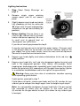
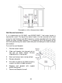
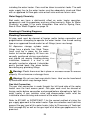
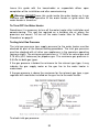
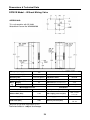
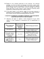
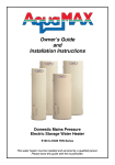
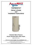
Owner’s Guide
and
Installation Instructions
Outdoor Domestic Mains Pressure
Gas Storage Water Heater
G270VE Series
This water heater must be installed and serviced by a qualified person.
Please leave this guide with the householder.
Warning: Upon completion of the installation and commissioning of the
water heater, leave this guide with the householder or responsible officer.
DO NOT leave this guide inside the cover of the water heater, as it may
interfere with the safe operation of the water heater or ignite when the
water heater is turned on.
Patents
This water heater may be protected by one or more patents or registered
designs in the name of Aquamax Australia Pty Ltd.
®
Trademarks
Registered trademark of Aquamax Australia Pty Ltd.
TM
Trademark of Aquamax Australia Pty Ltd.
1
CONTENTS
Householder: Read the section ‘About Your Water Heater’ (pages 3 to
19). The ‘Installation’ section is intended for the installer but may be of
interest.
ABOUT YOUR WATER HEATER ................................................................ 3
Model Type................................................................................................ 3
Lighting the Water Heater ......................................................................... 5
Shut Down Procedure ............................................................................... 8
Temperature Adjustment........................................................................... 8
Other Important Information ...................................................................... 9
Periodic Maintenance .............................................................................. 11
Water Chemistry...................................................................................... 14
Troubleshooting ...................................................................................... 17
INSTALLATION .......................................................................................... 20
Installation Overview ............................................................................... 20
Water Supplies ........................................................................................ 23
Plumbing & Plumbing Diagrams ............................................................. 24
Plumbing Connections......................................................................... 24
Two Temperature Zones Using a Temperature Limiting Device......... 28
Circulated Hot Water Flow & Return Systems .................................... 29
Commissioning ........................................................................................ 31
To Fill, Turn ON and Commission the Water Heater .......................... 31
Testing Inlet Gas Pressure .................................................................. 32
Draining the Water Heater ...................................................................... 35
Dimensions & Technical Data ................................................................. 36
WARRANTY ............................................................................................... 39
2
ABOUT YOUR WATER HEATER
Product Application
This water heater is designed for use in a single family domestic dwelling
for the purpose of heating potable water. Its use in an application other
than this may shorten its life.
Warning: This water heater is only intended to be operated by persons
who have the experience or knowledge and capabilities to do so. This
water heater is not intended to be operated by persons with reduced
physical, sensory or mental capabilities i.e. the infirm, or by children.
Children should be supervised to ensure they do not interfere with the
water heater.
Model Type
®
This Aquamax water heater is a 5 star permanent pilot gas storage water
heater suitable for outdoor installation only. This water heater is not to be
used as a pool heater.
Water is stored in a vitreous enamel storage cylinder and heated by a gas
burner located under the cylinder. The heat produced by the burner is
transferred to the water through the base, top and side walls of the storage
cylinder with flue baffle rings capturing heat to improve efficiency. The gas
supply to the burner is controlled by a thermostat so that the water in the
storage cylinder is heated and then maintained at a constant temperature.
Automatic safety controls are fitted to the water heater to provide safe and
efficient operation.
Model Selection Chart
Model Name
Model Number
G270VE
(without mixing valve)
G270VE-NG
G270VE-LP
Note: All models can be supplied with a ‘Hard Water Anode’. These models
have the suffix ‘HWA’ at the end of the model number.
Legend
G
270
VE
NG
LP
Gas Series
Rated first hour hot water delivery in Litres
Vitreous enamel storage cylinder
Natural gas
Propane gas
3
Mains Pressure Operation
This water heater is designed to operate at mains pressure by connecting
directly to the mains water supply. If the mains supply pressure in your area
exceeds that shown in ‘Mains Water Supply’ on page 23, a pressure
limiting valve must be fitted. The supply pressure should be greater than
350 kPa for true mains pressure operation to be achieved.
Hot Water Temperature
This water heater features a user adjustable thermostat located behind the
front access panel which controls the temperature of the stored water in
the storage cylinder. The thermostat is adjustable between 30 ~ 70°C
(factory setting approximately 60°C). Refer to ‘Temperature Adjustment’ on
page 8.
To meet the requirements of the National Plumbing Standard, the
temperature of the stored water must not be below 60°C.
Note: AS 3498 requires that a water heater provides the means to inhibit
the growth of legionella bacteria in stored potable water. This water heater
can satisfy this AS 3498 requirement provided it is operating and the
thermostat setting is set at 60°C or higher.
High Hot Water Temperature Increases the Risk of Scald Injury
Warning: This water heater can deliver water at temperatures which
can cause scalding. Always check the water temperature before use, such
as when entering a shower or filling a bath or basin, to ensure it is suitable
for the application and will not cause a scald injury. Aquamax recommends
monthly temperature checks to ensure the appropriate temperature is
maintained within the hot water heater.
Aquamax recommends, and it may also be required by regulations, that a
secondary device such as an approved temperature limiting device or antiscald water shut off valve be fitted into the hot water pipe work to the
bathroom(s) and ensuite(s) if persons living in the house require additional
safety protection from potential scalding. This will keep the hot water supply
temperature to the bathroom(s) and ensuite(s) below 50°C which will
reduce the risk of scald injury whilst still allowing hotter water (60°C+) to the
kitchen and laundry.
For new hot water installations, all sanitary outlet fixtures used primarily for
personal hygiene purpose must deliver hot water not exceeding 50°C. This
temperature limit is not mandatory for kitchen sinks and laundry tubs and
the preferable temperature setting for these outlets should be 60°C.
4
To minimise scalding, especially for those people in high scald risk
categories i.e. young children, people with potentially incapacitating
medical conditions, elderly people etc, this water heater must be installed in
accordance with AS/NZS 3500.4.
For early childhood centres, primary and secondary schools, nursing
homes or similar facilities for young, aged, sick or disabled persons, please
consult your local health authority for the correct temperature setting.
Lighting the Water Heater
Safety Warnings
For your safety, read the following warnings before attempting to light the
water heater:
Warning: This water heater is designed to operate reliably and safely
as long as the operating instructions are followed exactly. You must comply
with these lighting instructions at every stage.
Warning: Ensure the water heater is filled with water and the water
supply is turned on otherwise serious damage to the storage cylinder and
water heater components may occur.
Warning: After installation and before lighting the water heater, the
qualified installer must check all gas connections for leaks. The qualified
installer must also test the gas inlet (supply) pressure and burner gas
pressure.
Warning: Use only your hand to turn the gas knob, never use tools. If
the gas knob will not turn by hand, do not try to repair it, call a qualified
service technician. Force or attempted repair may cause a fire or
dangerous situation.
Warning: Do not attempt to operate this water heater if it has been
damaged. Call a qualified service technician.
Warning: This water heater is equipped with a ‘Piezo’ push button
igniter which lights the pilot. There is no need for matches to light the water
heater. When lighting the pilot, follow these instructions exactly.
5
Lighting Instructions
1.
Stop. Read ‘Safety Warnings’ on
page 5.
2.
Remove single screw retaining
access panel and lift out access
panel.
3.
Slightly depress gas knob and rotate
fully clockwise so that the white dot
‘‘ aligns with the gas knob position
indicator on the gas control body (off
position).
4.
Before lighting: Ensure there is no
smell of gas around vicinity of water
heater and burner opening. Be sure
to smell next to ground level as
some gases can settle there.
If you do not smell gas proceed to step 5.
If you do smell gas do not try to light the water heater. If the gas smell
is still present after five (5) minutes, turn off the isolation valve on the
gas supply line to the water heater, leave the area and call Aquamax
Service or a qualified service technician.
5.
Depress gas knob slightly and rotate anticlockwise to the red star ‘
(pilot) position.
’
6.
Depress gas knob fully (until red star disappears below housing) and
hold in the depressed position. After twenty (20) seconds, whilst
keeping gas knob depressed, repeatedly press and release the igniter
button for up to forty (40) seconds or until the pilot flame ignites (igniter
is a red button located below and to the right of the gas control).
Warning: Keep your face clear of combustion chamber opening
while operating igniter button.
If pilot ignites, proceed to step 7.
If pilot does not ignite, release gas knob, wait five (5) minutes for any
unburnt gas to escape then begin again from the beginning of step 6.
Note: It is not possible to depress the gas knob fully if the gas control
has activated its safety shut off feature. In this case, wait five
(5) minutes for the gas control to reset (this allows for any unburnt gas
to escape).
6
7.
Hold gas knob in depressed position for a further twenty (20) seconds
and then release.
8.
Depress gas knob slightly and rotate anticlockwise to the red line ‘l’
(ignition) position and hold in this position for five (5) seconds.
9.
Release gas knob (gas knob will return to the red flame ‘ ’ (on)
position automatically) and listen for burner noise.
10. If burner ignites, proceed to step 11.
If burner fails to ignite, depress gas knob slightly and rotate gas knob
to the white dot ‘‘ (off) position. Wait five (5) minutes for any unburnt
gas to escape and then begin again from step 5.
Warning: Failure to wait five (5) minutes may result in a fire or
dangerous situation.
11. When the burner remains alight with the gas knob released, rotate
temperature adjustment dial so that ‘4’ aligns with the temperature dial
position indicator on the gas control body. This is the recommended
(and factory default) setting which will provide a water temperature of
approximately 60°C. Rotate adjusting dial past this position if a higher
temperature is required. Refer to ‘Temperature Adjustment’ on page 8
for dial position indicative temperatures.
Note: To comply with the requirements of AS 3498 and to inhibit the
growth of Legionella bacteria, the thermostat setting must be set at
60°C or higher.
Warning: Hotter water increases the risk of scald injury.
12. Replace front access panel.
The main burner will now automatically ignite when heating is required and
extinguish when the water in the storage cylinder has been heated to the
set temperature. If the main burner does not light at the selected setting,
the water may already be at the selected temperature.
Note: Never press igniter button whilst gas knob is in other than the red
star ‘ ’ (pilot) position.
7
Shut Down Procedure
To view the gas control components described in this procedure refer to the
‘Lighting Instructions’ diagram on page 6.
1.
Remove front access panel by following step 2 of ‘Lighting
Instructions’ on page 6.
2.
Depress gas knob slightly and rotate gas knob clockwise so that the
red star ‘ ’ aligns with the gas knob position indicator on the gas
control body (pilot position). This setting will leave the pilot flame
alight, however the main burner will not be able to ignite.
Note: To reinstate the burner from the red star ‘ ’ (pilot) position,
depress gas knob slightly and rotate anticlockwise to the red line ‘l’
(ignition) position. Hold in this position for five (5) seconds then
release the gas knob. The gas knob will return to the red flame ‘ ’ (on)
position automatically and the burner will ignite when heating is
required and extinguish when the water in the storage cylinder has
been heated to the set temperature. If the main burner does not light
at the selected setting, the water may already be at the selected
temperature.
3.
Replace front access panel or to completely shut down the gas
control, perform steps 4 and 5.
4.
Depress gas knob slightly and rotate clockwise to the white dot ‘‘
(off) position. This setting shuts the gas control down completely.
Note: To reinstate the gas control and burner from the white dot ‘‘
(off) position, follow the ‘Lighting Instructions’ on page 6.
5.
Replace front access panel.
Note: When switched back on from the red star ‘ ’ (pilot) position or white
dot ‘‘ (off) position, the water heater may take up to an hour to reheat.
Temperature Adjustment
Warning: AS 3498 requires that a water heater provides the means to
inhibit the growth of Legionella bacteria in potable water. This water heater
can satisfy this AS 3498 requirement provided it is operating and the
thermostat setting is 60°C or higher.
Thermostat Adjustment – All Models
The thermostat controls the stored water temperature.
The thermostat automatically controls the gas supply to the burner so that a
constant water temperature is maintained within the storage cylinder. The
8
thermostat is fully automatic and the burner only operates when the water
in the storage cylinder requires heating. There is no need to switch the
water heater off when it is not in use, except when you are going away for
an extended period.
The temperature adjustment dial is on the front of the gas control located
behind the front access panel of the water heater (refer to the diagram in
‘Lighting Instructions’ on page 6). The adjustment dial is marked with
numerals with each number representing a temperature difference of
approximately 10°C. When aligned with the temperature dial position
indicator on the gas control body, the dial setting corresponds
approximately to the following temperatures:
Dial Setting
Temperature
1
30°C
2
40°C
3
50°C
4
60°C
5
70°C
To adjust the thermostat:
1.
Remove front access panel by following step 2 of ‘Lighting
Instructions’ on page 6.
2.
Rotate temperature adjustment dial anticlockwise to increase or
clockwise to decrease the stored water temperature.
Warning: Hotter water increases the risk of scald injury.
3.
Replace front access panel.
Other Important Information
Going Away?
If you plan to be away from home for one or two nights, we suggest you
leave the water heater switched on. However, if you plan to stay away
more than a few nights, the gas knob can be set to the red star ‘ ’ (pilot)
position to conserve energy (follow steps 1~ 3 of ‘Shut Down Procedure’ on
page 8).
Note: When switched back on, the water heater may take up to an hour to
reheat.
Safety
This water heater is supplied with a thermostat, an over temperature cut
out, a thermocouple and a combination pressure temperature relief valve.
These devices must not be tampered with or removed. The water heater
must not be operated unless each of these devices are fitted and are in
working order.
9
The Aquamax warranty may not cover faults if relief valves or other safety
devices are tampered with or if the installation is not in accordance with
these instructions.
Warning: For continued safety of this water heater, it must be installed,
operated and maintained in accordance with the Owner’s Guide and
Installation Instructions. These instructions must be read in conjunction with
all other instructions affixed to the appliance.
Warning: Do not store flammable or combustible materials near the
water heater. Flammable liquids (such as petrol), newspapers and similar
articles must be kept well away from the water heater and the flue terminal.
Warning: Do not use aerosols, stain removers and household
chemicals near the water heater whilst it is operating. Gases from some
aerosol sprays, stain removers and household chemicals are flammable
and/or become corrosive when drawn into a flame.
Warning: Do not store swimming pool chemicals, household
cleaners, etc., near the water heater.
Warning: Do not place anything in contact with the flue terminal.
Ensure the flue terminal is not obstructed in any way at any time.
How Long Will the Water Heater Last
The water heater is supported by a manufacturer’s warranty (refer to page
39). There are a number of factors that will affect the length of service the
water heater will provide. These include but are not limited to the water
chemistry, the water pressure, the water temperature (inlet and outlet) and
the water usage pattern.
Precautions
Where damage to property can occur in the event of the water heater
leaking, the water heater must be installed in a safe tray. Construction,
installation and draining of a safe tray must comply with AS/NZS 3500.4
and all local codes and regulatory authority requirements.
The water heater must be maintained in accordance with the Owner’s
Guide and Installation Instructions. Refer to ‘Periodic Maintenance’ on page
11.
If this water heater is to be used where an uninterrupted hot water supply is
necessary for your application or business, you should ensure that you
have back up redundancy within the hot water system design. This should
ensure the continuity of hot water supply in the event that this water heater
10
was to become inoperable for any reason. We recommend you seek advice
from your plumber or specifier about your needs and building back up
redundancy into your hot water supply system.
Periodic Maintenance
Minor Six Monthly Maintenance
It is recommended minor maintenance be performed every six months by
the dwelling occupant.
Warning: Exercise care when operating easing levers as water
discharged from the water heater may be of a very high temperature.
Minor maintenance actions:
1.
Operate easing lever on pressure temperature relief valve (refer to
‘Pressure Temperature Relief Valve’ on page 12).
2.
Operate easing lever on expansion control valve (if ECV fitted) (refer
to ‘Expansion Control Valve’ on page 13).
3.
If a safety tray is installed, check to ensure the safety tray drain pipe is
not blocked.
Annual Service
It is recommended an annual service be conducted on the water heater.
Servicing must be performed by a qualified person. Phone Aquamax
Service or their nearest Accredited Service Agent.
Annual service actions:
1.
Inspect and flush temperature pressure relief valve.
2.
Inspect and flush expansion control valve (if ECV fitted).
3.
Check and if necessary adjust burner gas pressure.
4.
Check piezo igniter, gas control and thermocouple condition and
operation.
5.
Check operation of and clean pilot and main burner.
6.
Visually check the water heater for any potential problems.
7.
Inspect all plumbing, gas and electrical connections.
Note: The water heater may need to be drained during this service and
may take up to an hour to reheat the water after servicing has been
completed.
11
Major Five (5) Year Service
It is recommended a major five (5) year service be conducted on the water
heater. Servicing must be performed by a qualified person. Phone
Aquamax Service or their nearest Accredited Service Agent.
Note: The five (5) year service and routine replacement of any
components, such as the relief valve(s), are not included in the Aquamax
warranty. A charge will be made for this work.
Major five (5) year service actions:
1.
Replace pressure temperature relief valve.
2.
Inspect and flush expansion control valve (if ECV fitted) and replace
expansion control valve if required.
3.
Inspect anode and replace anode if required. If the anode is not
replaced, it should be replaced within three (3) years of this service.
Refer to ‘Anode’ on page 13.
4.
Check and if necessary adjust burner gas pressure.
5.
Check piezo igniter, gas control and thermocouple condition and
operation.
6.
Check operation of and clean pilot and main burner.
7.
Visually check the water heater for any potential problems.
8.
Inspect all plumbing and gas connections.
Note: The water heater may need to be drained during this service and
may take up to an hour to reheat the water after servicing has been
completed.
Pressure Temperature Relief Valve (PTR valve)
The PTR valve is near the top of the water heater and is essential for safe
water heater operation. It is possible for the PTR valve to release a little
water through the drain line during each heating period. This occurs as the
water is heated and expands by approximately 1/50 of its volume.
Continuous leakage of water from the PTR valve and its
drain line may indicate a problem with the water heater
(refer to ‘Pressure Temperature Relief Valve Running’
on page 18).
Warning: Never block the outlet of the PTR valve
or its drain line for any reason.
Operate the easing lever on the PTR valve once every six months. It is
very important you raise and lower the lever gently.
12
Warning: Exercise care when operating easing lever as water
discharged from the water heater may be of a very high temperature.
Warning: Exercise care to avoid any splashing of water, as water
discharged from the drain line will be hot. Stand clear of the drain line’s
point of discharge when operating the valve’s lever.
Danger: Failure to perform this procedure may result in the water
heater storage cylinder failing.
If water does not flow freely from the drain line when the lever is lifted, then
the water heater must be checked. Phone Aquamax Service or their
nearest Accredited Service Agent to arrange for an inspection.
The pressure temperature relief valve should be replaced at intervals not
exceeding five (5) years, or more frequently in areas where there is a high
incidence of water deposits (refer to ‘Water Chemistry’ on page 14).
Expansion Control Valve (ECV)
In many areas, including South Australia, Western Australia and scaling
water areas, an ECV is fitted to the cold water supply line to the water
heater (refer to the ‘Cold Water Supply Plumbing Arrangement’ diagram on
page 25). The ECV may discharge a small quantity of water from its drain
line during the heating period instead of the PTR valve on the water heater.
Operate the easing lever on the expansion control valve once every six
months. It is very important that you raise and lower the lever gently.
The expansion control valve should be checked for performance or
replaced at intervals not exceeding five (5) years, or more frequently in
areas where there is a high incidence of water deposits (refer to ‘Water
Chemistry’ on page 14).
Anode
The anode installed in your water heater has been designed to slowly
dissipate whilst protecting the storage cylinder. If the hot water heater is not
used for two (2) weeks or more, a quantity of hydrogen gas, which is highly
flammable, may accumulate in the water heater. To dissipate this gas
safely, it is recommended that a hot tap be turned on for several minutes or
until discharge of gas ceases. Use a sink, basin, or bath outlet, but not a
dishwasher, clothes washer or other appliance. During this procedure,
there must be no smoking, open flame, or any electrical appliances
operating nearby. If hydrogen is discharged through the tap, it will probably
make an unusual sound similar to air escaping.
13
The life of the storage cylinder may be extended by arranging a qualified
person to periodically inspect the anode and replace if required. If the
anode is not replaced during a five (5) year service (refer to ‘Major Five (5)
Year Service’ on page 12) then the maximum time after installation when
the anode should be replaced for this electric water heater is eight
(8) years.
For water supplies which are either softened, desalinated or where the
water supply may alternate between a water tank and a reticulated public
supply or another supply, it is recommended the anode be replaced within
five (5) years of installation.
Change of Water Supply
The changing or alternating from one water supply to another can have a
detrimental effect on the operation and/or life expectation of the water
heater storage cylinder, pressure temperature relief valve and heating unit.
Where there is a changeover from one water supply to another, e.g. a
rainwater tank supply, bore water supply, desalinated water supply, public
reticulated water supply or water brought in from another supply, then
water chemistry information should be sought from the supplier or it should
be tested to ensure the water supply meets the requirements given in these
guidelines for the Aquamax warranty to apply.
Water Chemistry
This water heater must be installed in accordance with this advice to
be covered by the Aquamax warranty.
This water heater is manufactured to suit the water conditions of most
public reticulated water supplies. However, there are some known water
chemistries which can have detrimental effects on the water heater and its
operation and/or life expectancy. If you are unsure of your water chemistry,
you may be able to obtain information from your local water supply
authority. This water heater should only be connected to a water supply
which complies with these guidelines for the Aquamax warranty to apply.
Total Dissolved Solids (TDS)
Some water analysis reports may state the conductivity of the water rather
than the level of total dissolved solids. Conductivity, measured in
microsiemens per centimetre (µS/cm), is directly proportional to the TDS
content of the water. TDS, in mg/Litre, is approximately 70% of the
conductivity in µS/cm.
14
The Aquamax warranty will not cover resultant faults to the storage cylinder
if this water heater is connected at anytime to a water supply where the
TDS content of the water exceeds 600 mg/Litre.
In locations where TDS approaches 600 mg/Litre, e.g. due to sediment, we
strongly recommend fitting an appropriate filter to ensure water entering or
in the water heater does not exceed this level at any time i.e. due to
sediment build up.
Water Chemistry & Anode Type
Aquamax water heaters are designed to suit the water conditions of most
metropolitan supplies, where the Total Dissolved Solids (TDS) content of
the supply is less than 600 mg/Litre. For use in regions where the water
supply TDS exceeds 600 mg/Litre, the magnesium alloy anode (supplied
as standard, cap colour code ‘Black’) may become excessively reactive.
For safety reasons and the longevity of the anode, the magnesium anode
should be replaced with an aluminium alloy anode (cap colour code ‘Blue’)
available from your Aquamax supplier. Anode replacement must be carried
out by an Aquamax accredited service agent.
Warning: If the water supply has a TDS greater than 600 mg/Litre and
the anode has not been changed to a blue anode, there is the possibility
the anode may become overactive and hydrogen gas could accumulate in
the top of the water heater during long periods of no use.
If the water heater has not been used for two or more weeks, follow the
procedure detailed in the ‘Anode’ section on page 13 for safe dissipation of
the hydrogen gas build up inside the storage cylinder.
It must be noted that in areas where the TDS exceeds 600 mg/Litre, the
Aquamax warranty will not cover resultant faults on components including
the storage cylinder that fail due to the bad water conditions even though
an aluminium anode is fitted. Refer to ‘Water Chemistry Levels Affecting
Warranty’ on page 16 for water chemistry levels and components affected.
The life of the water heater may be extended by periodic inspection of the
anode and replacement if necessary (refer to ‘Periodic Maintenance’ on
page 11 and ‘Anode’ on page 13).
15
Water Chemistry Levels Affecting Warranty
The Aquamax warranty of this water heater will not cover resultant faults on
components including the storage cylinder where water stored in the
storage cylinder exceeds at any time any of the following levels:
Total dissolved solids
Total hardness
Chloride
Magnesium
pH
Calcium
Sodium
Iron
600 mg/Litre
200 mg/Litre
300 mg/Litre
10 mg/Litre
9.5 and not less than 6.5
20 mg/Litre
150 mg/Litre
1 mg/Litre
Scaling Water
Scaling water is water that contains levels of calcium carbonate (total
hardness in excess of 200 mg/Litre at any time when the water heater is
operating). Scaling water can block and prevent the pressure &
temperature relief valve from operating resulting in damage to the water
heater storage cylinder and water heater components.
An ECV is mandatory in SA & WA and must be fitted in ALL areas with
scaling water to assist in preventing blockage of the pressure and
temperature relief valve.
Danger: Failure to install an expansion control valve where scaling
water conditions occur may result in the water heater storage cylinder
failing.
To avoid damage to the storage cylinder and water heater components,
Aquamax strongly recommend scaling water be treated before entering the
water heater by fitting appropriate water filters/conditioners etc. Refer to
your Local Water Authority for information on water in your area. A build up
of white sediment on hot water taps or shower roses can be indicative of
scaling water. Contact Aquamax if this condition is observed.
Note: Damage caused by scaling water can affect the Aquamax warranty.
(Refer to ‘Water Chemistry Levels Affecting Warranty’ on page 16).
Spring, Dam, Bore & River Water Supplies
The Aquamax warranty of this water heater will not cover resultant faults on
components including the storage cylinder due to the effects of sludge
and/or sediment as a result of connection to a water supply from silted or
treated sources i.e. springs, dams, bores, rivers or towns supplied from a
bore.
16
Troubleshooting
Check the items below before making a service call. You will be charged
for attending to any condition or fault that is not related to the manufacture
or failure of a part. For warranty terms and conditions (refer to ‘Warranty’
on page 39).
Not Enough Hot Water (Or No Hot Water)
•
Is a pilot flame present?
Remove the front access panel and check that a pilot flame is present. If
the pilot flame is not burning relight the heater by following the ‘Lighting
Instructions’ on page 6.
•
Are you using more hot water than you think?
Is one outlet (especially the shower) using more hot water than you
think? Very often the amount of hot water used is not realised,
particularly when showering. Carefully review the family’s hot water
usage. Have your plumber fit a flow control valve to each shower outlet
to reduce water usage.
•
Pressure temperature relief valve running?
Is the PTR valve discharging too much water? (Refer to ‘Pressure
Temperature Relief Valve Running’ on page 18).
•
Is the thermostat setting appropriate?
Ensure the thermostat setting is appropriate. You may choose to adjust
the thermostat upwards to gain additional hot water capacity. Refer to
‘Temperature Adjustment’ on page 8.
Warning: Hotter water increases the risk of scald injury.
Water Not Hot Enough
•
Has your hot water usage increased?
You may find that due to heavy hot water usage the water temperature
may be lower than normally expected.
•
Is the thermostat setting correct?
Ensure the thermostat setting is correct. Refer to ‘Temperature
Adjustment’ on page 8.
17
Pressure Temperature Relief Valve Running
•
Normal Operation
It is normal and desirable for the PTR valve to allow a small quantity of
water to escape during the heating cycle, however there may be a
problem if the valve continuously dribbles more than a bucket full of
water in a normal 24 hr cycle.
•
Continuous dribble
Try gently raising the easing lever on the relief valve for a few seconds
(refer to ‘Pressure Temperature Relief Valve’ on page 12). This may
dislodge a small particle of foreign matter and clear the fault. Release
the lever gently.
•
Steady flows for long period (often at night)
This may indicate the mains water pressure sometimes rises above the
designed pressure of the water heater. Ask your installing plumber to fit
a pressure limiting valve.
Warning: Never use reconditioned relief valves and never replace
the relief valve with one of a higher pressure rating.
Expansion Control Valve Running
If an expansion control valve is fitted in the cold water supply line to the
water heater, it may discharge a small quantity of water instead of the
water heaters pressure temperature relief valve. This has the benefit of
conserving energy as the discharged water is cooler (refer to the ‘Cold
Water Supply Plumbing Arrangement’ diagram on page 25 for expansion
control valve location).
Can’t Light the Pilot
•
Is there gas to the water heater?
Check to ensure the gas isolation valve on the gas supply line to the
water heater is open.
•
Is there a normal gas supply to the rest of the premises?
Try lighting another gas appliance to check if there is a normal gas
supply present. If there is no gas, call the gas supplier.
Water Heater appears to be Leaking
When the water heater is first lit, or after a large usage of hot water,
condensation may form on and drip from the grille at the front of the water
heater. During periods of heavy condensation, condensate may also form
18
around the base of the water heater. This is quite normal, especially in
winter months and the condensate will dry off as the water is heated.
The water heater will drip water during the heating cycle. It is possible for
several litres a day of condensation to discharge from the unit, especially in
cool conditions. This water is not from the mains supply but is condensation
from the atmosphere caused by the efficient operation of the water heater.
Note: During the heating cycle it is not unusual to see water vapour clouds
steaming from the flue terminal. This is normal operation.
Higher Than Expected Gas Bills
Check the following points if your gas bill is higher than expected:
•
Is the relief valve running excessively?
Refer to ‘Pressure Temperature Relief Valve Running’ on page 18.
•
Is one outlet (especially the shower) using more hot water than you
think?
Refer to ‘Not Enough Hot Water’ on page 17.
•
Is there a leaking hot water pipe, dripping hot water tap, etc?
Even a small leak will waste a surprising quantity of hot water and gas.
Replace faulty tap washers and have your plumber rectify any leaks.
•
Has there been an increase in hot water usage?
An increase in hot water usage will result in an increase in water heater
operation.
•
Has your gas rate been increased by your gas retailer since your
previous bill?
Check your previous bill and compare gas rates and charges.
If you have checked all the previous troubleshooting points and still
believe you need assistance, phone Aquamax Service or their nearest
Accredited Service Agent.
19
INSTALLATION
Installation Overview
This water heater must be installed by a qualified person in accordance
with the installation instructions. The installation must comply with the
requirements of AS/NZS 3500.4, AS 5601 or AS/NZS 5601.1, all local
codes and regulatory authority requirements.
Check to ensure the water heater is suitable for the gas type available
(refer to the water heaters rating label).
All packaging materials must be removed from the water heater prior to its
installation. This includes the removal of the cardboard base of the carton
from the underside of the water heater.
This water heater is not suitable for pool heating.
Hot Water Redundancy
If this water heater is to be used where an uninterrupted hot water supply is
necessary for the application or business, then there should be redundancy
within the hot water system design. This should ensure the continuity of hot
water supply in the event that this water heater was to become inoperable
for any reason. We recommend you provide advice to the system owner
about their needs and building backup redundancy into the hot water
supply system.
Water Heater Location
This water heater is suitable for outdoor installation only. The water heater
should be installed close to the most frequently used outlet and its position
chosen with safety and service in mind.
Ensure people, particularly children, will not touch the flue outlet. The flue
terminal must be clear of obstructions including shrubbery.
Sufficient and safe space for ease of service and access to front access
cover, burner and relief valve should be considered when locating the
water heater. The water heater must be installed upright in a vertical
position and must be accessible without the use of a ladder or scaffold. If
adequate room is unavailable, the water heater must be disconnected,
drained and removed to enable servicing.
The water heater should be installed at ground level on a fire poof base,
such as a concrete or brick plinth, as approved by the local authority. The
water heater must stand vertically upright with the back of the water heater
against an external wall. Failure to observe this precaution can cause
problems in high wind areas. A secondary flue is not required.
20
It is a requirement of AS 5601 and AS/NZS 5601.1 that the water heater is
secured to a wall. A wall bracket is supplied with the water heater for this
purpose. The top of the unit is to be secured to the wall using the wall
bracket and masonry anchor provided (or other suitable fastener). Refer to
‘Wall Bracket Installation’ on page 22.
Note: Damage to the storage cylinder caused by incorrect installation is not
covered by warranty.
This water heater must not be installed in an area with a corrosive
atmosphere where chemicals are stored or where aerosol propellants are
released. Remember the air may be safe to breathe, but when it goes
through a flame, chemical changes take place which may attack the water
heater. Some chemicals and aerosol propellants are flammable and storing
or using these products near the water heater may cause fire or explosion.
The following restrictions to water heater location are from AS 5601 or
AS/NZS 5601.1 and are supplied here as a guide. The dimensions shown
in the table below are the minimum clearance distances from the flue
terminal. These clearances must be observed at all times.
Below eaves balconies and other projections
From the ground, above a balcony or other surface
From a return wall or corner. Refer example (a) in diagram
From a gas meter
From an electricity meter box or fuse box
From a drain pipe or soil pipe
Horizontally from any building structure or obstruction facing a
terminal
From any other flue terminal, cowl or combustion air intake
Horizontally from an openable window, door, non mechanical air
inlet, or any other opening into a building with the exception of
sub floor ventilation. Refer example (b) in diagram
From a mechanical air inlet, including a spa blower
Vertically below an openable window, non mechanical air inlet, or
any other opening into a building with the exception of sub floor
ventilation. Refer example (c) in diagram
From any other combustible material
All dimensions in mm.
21
300
300
500
1000
500
150
500
500
500
1500
500
500
Examples a, b & c from previous table
Wall Bracket Installation
It is a requirement of AS 5601 and AS/NZS 5601.1 that water heater is
secured to a wall. The top of the water heater is to be secured to the wall
using the wall bracket and M6.5 masonry anchor provided with the water
heater (or other suitable fastener). It is necessary to fix the bracket to the
wall after positioning the water heater but prior to making the water and gas
connections.
To install the wall bracket:
1.
Position water heater.
2.
Slide wall bracket into formed slot at
top rear of water heater. Ensure
angled profile is facing wall.
3.
Mark wall where hole is to be drilled.
4.
Remove bracket.
5.
Drill hole to receive the M6.5 masonry
anchor (or other suitable fastener).
6.
Replace wall bracket with angled
profile facing wall.
7.
Secure wall bracket to wall.
22
Safe Tray
Where damage to property can occur in the event of the water heater
leaking, the water heater must be installed in a safe tray. Construction,
installation and draining of a safe tray must comply with AS/NZS 3500.4
and all local codes and regulatory authority requirements. AS/NZS 3500.4
also has particular requirements when a safe tray must be installed.
Flashing Kit
When attaching a Flashing Kit to the water heater jacket, we recommend
the use of self-drilling screws with a maximum length of 12 mm. An
effective seal must be achieved where the screw penetrates the jacket. The
Flashing Kit must not be installed within a 100 mm wide vertical strip either
side of the cold water inlet, hot water outlet and pressure temperature relief
valve. Flashing Kits are available from Aquamax and if required are
purchased as a separate kit. The kit part number is:
Model
G270VE
Flashing Kit Part No.
AQ1184105
Note: If the water heater or storage cylinder is damaged as a result of
installing the Flashing Kit, any resultant faults will not be covered by the
Aquamax warranty.
Water Supplies
Mains Water Supply
Where the mains water supply pressure exceeds that shown in the table
below, an approved pressure limiting valve is required and should be fitted
after the stop cock and before the non return valve as shown in the ‘Cold
Water Supply Plumbing Arrangement’ diagram on page 25.
Model
Pressure temperature relief valve setting
Expansion control valve (ECV) setting *
With ECV
Max mains supply pressure
Without ECV
G270VE
1400 kPa
1200 kPa
960 kPa
1120 kPa
* Expansion control valve not supplied with water heater.
Tank Water Supply
If the water heater is supplied with water from a tank supply and a pressure
pump system is not installed, then the bottom of the supply tank must be at
least 1 m above the highest point of the hot water plumbing system,
23
including the water heater. Care must be taken to avoid air locks. The cold
water supply line to the water heater must be adequately sized and fitted
with an approved full flow gate valve or ball valve and non return valve.
Water Supply Chemistry
Bad water can have a detrimental effect on water heater operation,
components and life expectancy and may affect warranty. Refer to ‘Water
Chemistry’ on page 14 for more information. Also refer to ‘Spring, Dam,
Bore & River Water Supplies’ on page 16.
Plumbing & Plumbing Diagrams
Plumbing Connections
All pipe work must be cleared of foreign matter before connection and
purged before attempting to operate the water heater. Use thread sealing
tape or an approved thread sealant on all fittings (never use hemp).
All Aquamax storage cylinder water
fittings have a plastic liner fitted. These
liners must be in place for the water
heater to function properly. All liners are
correctly positioned during manufacture
and should not require handling during
installation, however if a liner is not
correctly inserted or aligned, it should be
gently pushed back into place before
connecting any plumbing fittings.
Warning: Plastic liners must be in place for the water heater to function
properly. Do not remove or damage liners.
Warning: Do not use heat near plastic liners. Heat can be transferred
by conduction which may damage liners.
Gas Inlet Connection
The gas inlet connection is made through the left hand side of the water
heater near the front access panel. Gas pipe work must be cleared of
foreign matter before connection and purged before attempting to light the
water heater. A gas isolation valve and disconnection union must be
installed to allow servicing and removal of the water heater.
Refer to AS 5601 or AS/NZS 5601.1 for the correct method of sizing the
gas supply pipe work to the water heater. Pipe size selection must take into
account the gas input of this water heater (refer to ‘Dimensions & Technical
Data’ on page 35) as well as the gas input of all other gas appliances in the
premises.
24
Natural Gas Models: Remove yellow warning label from gas control after
connecting gas supply line.
Propane Gas Models: A gas regulator is supplied with the water heater
and must be installed externally between the gas isolation valve and jacket
of the water heater. Refer to gas flow directional arrow on regulator body to
ensure it is installed in the correct orientation. The regulator has been
factory preset to obtain a burner pressure of approximately 2.7kPa.
Warning: Always isolate the water heater before pressure testing the
gas supply system. Disconnect water heater after isolating valve to prevent
the risk of serious damage to the gas control. The Aquamax warranty does
not cover damage of any nature resulting from failure to observe this
precaution. Refer to water heaters rating label for gas pressures.
Warning: Care is necessary when tightening fittings into gas control as
the gas control casting may crack if fittings are over tightened. Cracked
control castings are not covered under the Aquamax warranty. A damaged
gas control must be replaced.
Water Inlet & Outlet Connections
An approved isolation valve and non return valve must be installed in the
supply line to the water heater.
A pressure limiting valve and expansion control valve may also be required
(for PLV requirements refer to ‘Water Supplies’ on page 23 and for ECV
requirements refer to ‘Expansion Control Valve’ on page 26).
A disconnection union must always be provided at the cold water inlet and
hot water outlet of the water heater to allow for water heater disconnection.
25
Expansion Control Valve
In some areas, local regulations may make it mandatory to install an
expansion control valve (ECV) in the cold water line to the water heater.
Refer to ‘Scaling Water’ on page 16.
The ECV must always be installed after the non return valve and be the last
valve installed prior to the water heater (refer to the ‘Cold Water Supply
Plumbing Arrangement’ diagram on page 25). A copper drain line must be
fitted to the ECV (refer to ‘Relief Valve Drain(s)’ on page 26).
Pressure Temperature Relief valve (PTR valve)
The pressure temperature relief (PTR) valve must be fitted before the water
heater is operated. Before fitting the PTR valve, make sure the valve probe
has not been bent. Seal the valve thread with thread sealing tape (never
use hemp) and ensure the tape does not protrude past the end of the
thread.
Screw the PTR valve clockwise into the right hand side opening on the
water heater marked ‘PTR’ (refer to diagram on page 36) with the valve
outlet pointing downwards. Do not use a wrench on the valve body – use a
spanner on the spanner flats. A copper drain line must be fitted to the PTR
valve (refer to ‘Relief Valve Drain(s)’ on page 26).
The valve is supplied with an insulation collar. This must not be removed.
The valve must be insulated with closed cell polymer insulation or similar
(minimum thickness 9 mm) and the insulation installed so as not to impede
the operation of the valve. The insulation must be weatherproof and UV
resistant if exposed.
Relief Valve Drain(s)
DN15 copper drain lines must be fitted to the ECV and PTR valve (if one is
installed) to carry the discharge clear of the water heater. Connect the drain
lines to the valves using disconnection unions. The drain line from the valve
to the point of discharge should be as short as possible, have a continuous
fall all the way from the water heater to the discharge outlet and have no
tap, valves or other restrictions in the pipe work. A drain line from a relief
valve must comply with the requirements of AS/NZS 3500.4.
A drain line must be no longer than 9 metres with no more than three
bends greater than 45° before discharging at an outlet or air break. The
maximum length of 9 metres for a drain line is reduced by 1 metre for each
additional bend required of greater than 45°, up to a maximum of three
26
additional bends. Where the distance to the point of final discharge
exceeds this length, the drain line can discharge into a tundish.
Subject to local regulatory authority approval, the drain lines from the ECV
and PTR valve from an individual water heater may be interconnected.
The outlet of a drain line must be in such a position that flow out of the pipe
can be easily seen, but arranged so discharge will not cause injury,
damage or nuisance. The termination point of a drain line must comply with
the requirements of AS/NZS 3500.4. Drain lines must not discharge into a
safe tray.
In locations where water pipes are prone to freezing, drain lines must be
insulated, must not exceed 300mm in length and are to discharge into a
tundish through an air gap of between 75mm and 150mm.
If a drain line discharges into a tundish, the drain line from the tundish must
be not less than DN20. The drain line from a tundish must meet the same
requirements as for a drain line from a relief valve.
Warning: As the function of the PTR valve on this water heater is to
discharge high temperature water under certain conditions, it is strongly
recommended the pipe work downstream of the relief valve be capable of
carrying water exceeding 93°C. Failure to observe this precaution may
result in damage to pipe work and property.
Pipe sizes
To achieve true mains pressure operation, the cold water line to the water
heater should be the same size or larger than the hot water line from the
water heater.
Hot water system pipe work must be sized according to the individual
application by persons competent to do so. Reference to the technical
specifications of the water heater and local regulatory authority
requirements must be made.
Pipe Work Insulation
To reduce heat loss, the cold water line to and the hot water line from the
water heater must be insulated in accordance with the requirements of
AS/NZS 3500.4. The insulation must be weatherproof and UV resistant if
exposed.
Saddling Pipe Work
To prevent damage to the storage cylinder it is not permissible to drill
through the jacket of the water heater except when attaching a Flashing Kit.
Refer to ‘Flashing Kit’ on page 23. Note: If the water heater or storage
27
cylinder is damaged as a result of installing a Flashing Kit, any resultant
faults will not be covered by the Aquamax warranty.
Two Temperature Zones Using a Temperature Limiting Device
This water heater can deliver water at temperatures which can cause
scalding. It is necessary and we recommend that a temperature limiting
device be fitted between the water heater and the hot water outlets in any
ablution area such as a bathroom or ensuite, to reduce the risk of scalding.
The installing plumber may have a legal obligation to ensure the installation
of this water heater meets the delivery water temperature requirements of
AS/NZS 3500.4 so that scalding water temperatures are not delivered to a
bathroom, ensuite or other ablution area.
Where a temperature limiting device is installed adjacent to the water
heater, the cold water line to the temperature limiting device can be
branched off the cold water line either before or after the isolation valve,
pressure limiting valve and non return valve to the water heater. If the cold
supply branch to the TLD is connected downstream of the water heater
non-return valve then we recommend that copper pipe or suitable high
temperature plastic pipe be used. This pipe work may be subject to high
water temperature and high water pressure. If an expansion control valve
is required, it must always be installed after the non return valve and be the
last valve prior to the water heater.
If a pressure limiting valve is installed on the cold water line to the water
heater and the cold water line to a temperature limiting device branches off
before this valve or from another cold water line in the premises, then a
pressure limiting valve of an equal pressure setting may be required prior to
the temperature limiting device.
28
Two Temperature Zone Plumbing Diagram
Circulated Hot Water Flow & Return Systems
For circulated hot water flow and return systems, a temperature limiting
device can only be installed on a dead leg which branches off the circulated
hot water flow and return pipe.
Warning: Installing a temperature limiting device in the circulated flow
and return pipe work, or circulating tempered water from a temperature
limiting device may cause water to be delivered to ablution areas at a
temperature exceeding the requirements of AS/NZS 3500.4.
29
Circulated Hot Water Flow & Return Plumbing Diagram
30
Commissioning
To Fill, Turn ON and Commission the Water Heater
Warning: The pilot or burner must not be lit until the water heater is
filled with water.
1.
Open all hot water taps in premises including shower(s).
2.
Fully open cold water isolation valve on cold water line to water heater.
This will purge air from hot water plumbing lines via taps opened in
step 1.
3.
Close each hot water tap after all air is purged (when air is purged
water will run freely without air bubbles or spluttering).
4.
Check all plumbing connections for leaks.
5.
Fully open gas isolation valve on gas supply line to water heater.
6.
Check all gas connections for leaks using a soapy water solution.
7.
Test inlet gas pressure (refer to ‘Testing Inlet Gas Pressure’ on page
32).
8.
Test gas burner pressure and adjust if required (refer to ‘Testing &
Adjusting Burner Gas Pressure’ on page 33).
9.
Light the water heater (refer to ‘Lighting Instructions’ on page 6).
10. Test water heater operation. Water heater operation must be
thoroughly checked as follows:
•
The pilot should burn with a small blue flame. A luminous yellow
or ‘floating’ flame is not acceptable.
•
The burner flame must light smoothly and quickly from the pilot
flame, and must go out quietly and completely.
•
The main burner flame must be stable, although slight lifting at
the front edge of the burner is acceptable when the burner is cold.
•
The main burner flame should be blue, with a clearly defined
inner cone. Luminous yellow or ‘floating’ flames are not
acceptable.
•
If unable to get the water heater working properly, contact
Aquamax Service or their nearest Accredited Service Agent.
11. Replace front access panel.
Explain to the householder, or a responsible officer, the functions and
operation of the water heater.
31
Leave this guide with the householder or responsible officer upon
completion of the installation and after commissioning.
Warning: DO NOT leave this guide inside the water heater as it may
interfere with the safe operation of the water heater or ignite when the
water heater is turned on.
To Turn OFF the Water Heater
Sometimes it is necessary to turn off the water heater after installation and
commissioning. This may be required on a building site or where the
premises are vacant. To turn off the water heater refer to ‘Shut Down
Procedure’ on page 8.
Testing Inlet Gas Pressure
The inlet gas pressure (gas supply pressure) to the water heater must be
checked as part of the commissioning procedure. The inlet gas pressure
must be checked with all other gas appliances in the premises operating
(burners alight). The minimum gas pressure is 1.13 kPa for natural gas and
2.75 kPa (±5% tolerance) for propane gas. The maximum gas pressure is
3.5 kPa for both gas types.
If the gas pressure is below the minimum for the relevant gas type, it may
indicate the gas supply meter or the gas line to the water heater is
undersized.
If the gas pressure is above the maximum for the relevant gas type, a gas
regulator will need to be installed on the gas line to the water heater.
To check inlet gas pressure:
32
1.
Ensure all other gas appliances in the premises are operating (burners
alight).
2.
Ensure water heater is turned off and gas control is completely shut
down (refer to ‘Shut Down Procedure’ on page 8).
3.
Remove screw from inlet gas pressure test point on gas control and
attach manometer hose to test point.
4.
Light the water heater and ensure burner is operating (refer to
‘Lighting Instructions’ on page 6).
5.
Take manometer reading with burner operating.
6.
Turn off water heater by completely shutting down gas control (refer to
‘Shut Down Procedure’ on page 8).
7.
Remove manometer hose from inlet gas pressure test point and
replace test point screw.
8.
Test inlet gas pressure test point for leaks using a soapy water
solution.
9.
If inlet gas pressure is correct, light the water heater and ensure
burner is operating (refer to ‘Lighting Instructions’ on page 6). If inlet
gas pressure is incorrect, contact Aquamax service.
10. Replace front access panel.
Testing & Adjusting Burner Gas Pressure
The burner gas pressure must be checked and adjusted (where applicable)
as part of the commissioning procedure. The burner gas pressure should
be 1.0 kPa for natural gas models and 2.7 kPa (±5% tolerance) for propane
gas models with the burner operating (alight). Refer to ‘Gas Control
Component Diagram’ on page 31 for component location.
To check and adjust burner gas pressure:
1.
Ensure water heater is turned off and gas control is completely shut
down (refer to ‘Shut Down Procedure’ on page 8).
2.
Using a small flat bladed screwdriver, lever and remove the black
plastic cover surrounding burner gas pressure test point on gas
control.
3.
Remove screw from burner gas pressure test point and attach
manometer hose to test point.
4.
Light the water heater and ensure burner is operating (refer to
‘Lighting Instructions’ on page 6).
33
5.
Take manometer reading with burner operating.
If reading is 1.0 kPa for natural gas models or 2.7 kPa (±5% tolerance)
for propane gas models, the burner gas pressure is correct. Proceed
directly to step 7.
If reading is not 1.0 kPa for natural gas models or 2.7 kPa (±5%
tolerance) for propane gas models, the burner gas pressure will
require adjusting in which case proceed to step 6a for natural gas
models or step 6b for propane gas models.
6.
a. Natural Gas Models
i.
Remove temperature adjustment dial using a small flat bladed
screwdriver; lever and pull dial away from gas control.
ii.
Using a small flat bladed screwdriver, rotate burner pressure
adjustment screw (marked P.R.ADJ.) clockwise to increase or
anticlockwise to decrease burner gas pressure until manometer
reads 1.0 kPa. Proceed to step 7.
b. Propane Gas Models
i. Using a 1.5mm thick flat bladed screw driver, remove the LPG
gas regulator cap by rotating anticlockwise.
ii.
Using a No. 2 Phillips head screw driver, rotate adjustment point
clockwise to decrease or anticlockwise to increase the burner gas
pressure until manometer reads 2.7 kPa.
iii.
Replace the regulator cap once burner pressure of 2.7 kPa is
achieved. Proceed to step 7
7.
Turn off water heater by completely shutting down gas control (refer to
‘Shut Down Procedure’ on page 8).
8.
Remove manometer hose from burner gas pressure test point and
replace test point screw.
9.
Light the water heater and ensure burner is operating (refer to
‘Lighting Instructions’ on page 6).
10. Test burner gas pressure test point for leaks using a soapy water
solution.
11. Replace black plastic cover surrounding burner gas test point by
pushing back into position. For natural gas models, replace
temperature adjustment dial.
12. Replace front access panel.
34
Draining the Water Heater
Warning: Water discharged from the water heater during this
procedure may be of a very high temperature. Wear personal protective
equipment (PPE) to reduce the risk of scalding.
To drain the water heater:
1.
Ensure water heater is turned off and gas control is completely shut
down (refer to ‘Shut Down Procedure’ on page 8).
2.
Close cold water isolation valve on cold water line to water heater.
3.
Close all hot water taps in premises.
4.
Operate PTR valve lever for a period of five (5) seconds to release
pressure in water heater. Note: Operate lever gently and do not let
lever snap back or you will damage relief valve seat.
5.
Undo union at cold water inlet to water heater and attach a hose to
water heater side of union. Run other end of hose to a drain.
6.
Operate PTR valve lever until all water has drained from water heater.
Operating PTR valve lever will let air into the water heater which will
allow water to drain through hose.
35
Dimensions & Technical Data
G270VE Model – Without Mixing Valve
APPROVALS:
This unit complies with AS 3498
WaterMark Licence No. WMKA00200
Storage capacity (L)
135
Hot water delivery (L)
140
Cold water inlet
135 L/Hr @ 45°C
Hot water outlet
RP¾/20
PTR valve
RP½/15
Recovery rate *
First hour capacity (L)
Mass
(kg)
Connections
270
RP¾/20
Empty
65
Gas inlet (flared compression)
Full
200
Condensate drain
960
Hourly consumption (MJ/hr)
Max Supply Pressure
With ECV (kPa)
½/15
On request
Gas Details
30
Without ECV (kPa)
1120
Min supply pressure (kPa)
NG: 1.13 or
LP: 2.75
ECV setting (kPa)
1200
Max supply pressure (kPa)
NG & LP: 3.5
PTR Valve (kPa)
1400
Burner pressure (kPa)
* Based on an inlet water temperature of 15°C.
Technical data is subject to change.
36
NG: 1.0 or
LP: 2.7
This page is intentionally blank
37
This page is intentionally blank
38
WARRANTY
AQUAMAX GAS DOMESTIC MAINS PRESSURE
WATER STORAGE HEATER WARRANTY
– AUSTRALIA ONLY1. THE AQUAMAX WARRANTY - GENERAL
1.1 This warranty is given by Aquamax Australia Pty Limited,
ABN 37 138 189 689 of 463-467 Warrigal Road, Moorabbin Victoria.
1.2 Aquamax offer a trained and qualified service network who will repair
or replace components at the address of the water heater subject to
the terms of the Aquamax warranty. Aquamax Service, in addition can
provide preventative maintenance and advice on the operation of your
water heater. The Aquamax Service contact number is available 7
days a week on 1800 676 000 from 9am to 5pm, excluding public
holidays (hours subject to change without notification).
1.3 For details about this warranty, you can contact us on 1800 676 000 or
by email at [email protected] (not for service bookings).
1.4 The terms of this warranty are set out in section 2 and apply to water
heaters manufactured after 1st August 2012.
1.5 If a subsequent version of this warranty is published, the terms of that
warranty will apply to water heaters manufactured after the date
specified in the subsequent version.
2. TERMS OF AQUAMAX WARRANTY AND EXCLUSIONS TO IT
2.1 The decision of whether to repair or replace a faulty component is at
Aquamax’s sole discretion.
2.2 If you require a call out and we find that the fault is not covered by
Aquamax warranty, you are responsible for our standard call out
charge. If you wish to have the relevant component repaired or
replaced by Aquamax, that service will be at your cost.
2.3 Where a failed component or cylinder is replaced under this warranty,
the balance of the original warranty period will remain effective. The
replacement does not carry a new Aquamax warranty.
39
2.4 Where the water heater is installed outside the boundaries of a
metropolitan area as defined by Aquamax or further than 25 km from
either a regional Aquamax branch office or an Accredited Aquamax
Service Agent’s office, the cost of transport, insurance and travelling
between the nearest branch office or Aquamax Accredited Service
Agent’s office and the installed site shall be the owner’s responsibility.
2.5 Where the water heater is installed in a position that does not allow
safe or ready access, the cost of that access, including the cost of
additional material handling and/or safety equipment, shall be the
owner’s responsibility. In other words, the cost of dismantling or
removing cupboards, doors or walls and the cost of any special
equipment to bring the water heater to floor or ground level or to a
serviceable position is not covered by this warranty.
2.6 This warranty only applies to the original and genuine Aquamax water
heater in its original installed location and any genuine Aquamax
replacement parts.
2.7 The Aquamax warranty does not cover faults that are a result of:
a. Accidental damage to the water heater or any component (for
example: (i) Acts of God such as floods, storms, fires, lightning
strikes and the like; and (ii) third party acts or omissions).
b. Misuse or abnormal use of the water heater.
c.
Installation not in accordance with the Owner’s Guide and
Installation Instructions or with relevant statutory and local
requirements in the State or Territory in which the water heater
is installed.
d. Connection at any time to a water supply that does not comply
with the water supply guidelines as outlined in the Owner’s
Guide and Installation Instructions.
e. Repairs, attempts to repair or modifications to the water heater
by a person other than Aquamax Service or an Aquamax
Accredited Service Agent.
f.
Faulty plumbing or faulty gas supply.
g. Failure to maintain the water heater in accordance with the
Owner’s Guide and Installation Instructions.
h. Transport damage.
i.
Fair wear and tear from adverse conditions (for example,
corrosion)
j.
Cosmetic defects.
40
2.8 Subject to any statutory provisions to the contrary, this warranty
excludes any and all claims for damage to furniture, carpet, walls,
foundations or any other consequential loss either directly or indirectly
due to leakage from the water heater, or due to leakage from fittings
and/or pipe work of metal, plastic or other materials caused by water
temperature, workmanship or other modes of failure.
2.9 If the water heater is not sized to supply the hot water demand in
accordance with the guidelines in the Aquamax water heater literature,
any resultant fault will not be covered by Aquamax warranty.
3. WHAT IS COVERED BY AQUAMAX WARRANTY FOR THE WATER
HEATERS DETAILED IN THIS DOCUMENT
3.1 Aquamax will repair or replace a faulty component of your water
heater if it fails to operate in accordance with its specifications as
follows:
What components
are covered
All components
The cylinder
(if the water heater is
installed in a singlefamily domestic
dwelling)
The cylinder
(if the water heater is
not installed in a
single-family domestic
dwelling)
The period in
which the fault
must appear in
order to be
covered
What coverage you receive
Year 1
Repair and/or replacement of
the faulty component, free of
charge, including labour.
Year 2 to 5
Replacement cylinder, free of
charge. Installation and repair
labour costs are the
responsibility of the owner.
Year 1
Repair and/or replacement of
the faulty component, free of
charge, including labour.
41
4. ENTITLEMENT TO CLAIM UNDER THIS WARRANTY
4.1 To be entitled to make a claim under this warranty, you need to:
a.
Be the owner of the water heater or have consent of the owner
to act on their behalf.
b.
Contact Aquamax Service without undue delay after detection
of the defect and, in any event, within the applicable warranty
period.
4.2 You are not entitled to make a claim under this warranty if your water
heater:
a. Does not have its original serial numbers or rating label.
b. Is not installed in Australia.
5. HOW TO MAKE CLAIM UNDER THIS WARRANTY
5.1 If you wish to make a claim under this warranty, you need to:
a.
Contact Aquamax on 1800 676 000 and provide owner’s
details, address of the water heater, a contact number and
date of installation of the water heater or if that’s unavailable,
the date of manufacture and serial number (from the rating
label on the water heater).
b.
Aquamax will arrange for the water heater to be tested and
assessed on-site.
c.
If Aquamax determines that you have a valid warranty claim,
Aquamax will repair or replace the water heater in accordance
with this warranty.
5.2 Any expenses incurred in the making of a claim under this warranty
will be borne by you.
6. THE AUSTRALIAN CONSUMER LAW
6.1 Our goods come with guarantees that cannot be excluded under the
Australian Consumer Law. You are entitled to a replacement or refund
for a major failure and for compensation for any other reasonably
foreseeable loss or damage. You are also entitled to have the goods
repaired or replaced if the goods fail to be of acceptable quality and the
failure does not amount to a major failure.
6.2 The Aquamax’s warranty (set out above) is in addition to any rights
and remedies that you may have under the Australian Consumer Law.
42
INSTALLER INFORMATION
DEAR INSTALLER,
Please provide the following information upon completion of the installation.
This information should be provided to Aquamax to assist the customer in
the event that a claim is made under the Aquamax warranty.
Plumber (Name & Company):
Plumber’s licence number:
Compliance Certificate:
(if applicable in your state)
Installation date:
Model & serial number:
Water Heater date of manufacture:
AQUAMAX AUSTRALIA PTY. LTD
ABN 37 138 189 689
www.aquamax.com.au
FOR SERVICE TELEPHONE
1800 676 000
NOTE: Every care has been taken to ensure accuracy in preparation of this
publication. No liability can be accepted for any consequences, which may
arise as a result of its application.
Revision Date: 26/03/2012
AQ0901022-J
43