1
I
MUTIUC
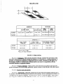
MIL-STD-1472E
3I October 1996
SUPERSEDING
MIL-STD-1472D
10 February 1994
DEPARTMENT
OF DEFENSE
DESIGN CRITERIA STANDARD
HUMAN
AMSC TU/A
~[STRJIN.TION STATEMENTL A:
ENGINEERING
AREA HF’AC
Approvccl for public rclcasc: distribution is unlimited
[
MII..-ST1472E2E
FOWWORD”
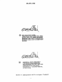
1. Tlis standard has been approved for use by all Departments and Agencies of the
Department of Defense.
2. This standard establishes general human engineering criteria for design and development of
Military systems, equipment and facilities. 1ts purpose is to present human engineering design criteria,
principles and practices to be applied in the design of systems, equipment and facilities so as to:
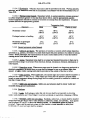
a. Achieve required performance by operator, control and maintenance personnel
h. Minimim skill and personnel requirements and training time.
c.
Achieve required reliability of personnel-equipment
combinations
d. Foster design standardization within and among systems.
4. ‘Ibis standard does not alter requirements for system development participation of human
engineering specialists to interpret and implement these practices and to provide solutions to human
engineering problems which arise and which are not specifically covered herein.
5. The use of the words “shall,” “should,” “may,” and “will” in this standard is in accordance
with MIL- STD-962, wherein “shall” expresses a provision that is binding, “should” and “may”
express non mandatory provisions, and “will” expresses a declaration of purpose or simple futurity.
6. Requirements herein are expressed in the lntemationrd System of units (S1). As a
convenience, the metric units are accompanied by their approximate customary system equivalents (in
parentheses). Angular measure is expressed in degrees unless it is necessary to speci& fractions of a
degree where milliradians are used.
7. Beneficial comments (recommendations, additions, deletions) and any pertinent data which
may be of use in improving this document should k addressed to Commander, U.S. Army Missile
Command, ATTN: AMSMI-RD-SE-TD-ST, Redstone Arsenal, AL 35898-5270 by using the selfaddressed Standardization Document Improvement Proposal (DD Form 1426) appearing at the end of
this document or by letter.
Ml L-STD- 1472E
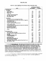
CONTENTS
PAGE
PARAGUPH
FOREWORD
SCOPE
:,1
1.2
1.3
:::
. . . . . . . . . . . . . . . . . . ....------.--—
. ..-.
-.—
---
—-
—..——.-
..
Scope -------------------------------------..-----——-----Purpose -------- --.----. -------- .-. —------—
—----—--————--—Application ---------------------------——
---—--—---..------.-.—Foree Limits ------—-—-—---— —-—--—
-.--—--——--——-—Manufaeturing tolerances---—-———
2
2.1
2.2
2.3
2,4
APPLICABLE DOCUMENTS
---------------------- -------- ..- —-. ——
General ----------------------------Government documents ------——---—--——-————————
--- ——— —-—. -.
Non-govmunent publications ———————
-—-—
---——-—-. —
---——
Orck!$of predence
3
DEFINITIONS
4
4.1
4.2
4.3
4.4
4.5
4.6
:;:
4,9
4.10
4.11
GENERAL RECXJIREMENTS
--------.— ——————
Objectives ------------—-----—
----—Standardization -—--—
--.
---—-—.-----------.----—
Function allocation ——
Human engineering design---——-————
———--——Fail safk design
—-——-.-—
— .-. ——
~ Simplicity of design——--hteracbon — -.— -——
safety -------——--—-——”
————-----.-------.-----.—.
Ruggedness --—
——
DcSignfix NBcs ~v “
Deai$n fw ekxromagnetic pulse @MP) hardening-———————
:.1
5.1.1
5.1.2
5.1.3
5.1.4
DETAILED
cmREMnm
-.. --— --------yb%:k
integrabn
—-—.-.——.
-——
Position relationships ----—-——————
Movement relationships-—————— ----—---.----.—------————
\
—
. . . . .. ... .—--Gmw&pkymovamwtlwio
%1
5.2.2
5.2.2.1
5.2.2.2
5.2.2.3
5.2.2.4
5.2.3
5.2.3.1
5,7 32
5.2.3.3
~,~ 4
52,5
——.
—-. —-—----—
-------------------Wswldi+ys
--------------------------------------------------------------------------Cknm””
.———.—..
Transilluminated displays General ----———-—
—--— -—.. --. -.---— ----------------Legend lights -------------------------------------------------------------------s~c
~~~~
l@~ -----.----:-------.-.--.-----..-:------------------------------Transilhminated panel assembhes --------------------------------------------------Scale indicators -:----------------------------------------------------------------------.
.
(klncitd —-- —----. . .. .. . .. .. . . . . ..“--- ..
Moviry-mhcr.
fixed-sale displays ----------------------------------------------Fixed-pointer, nw@-We
displays -. -- .-.- . ----,----------. -----. -. . ”------------( ‘nttmcterav tuk clisptzqs ---.-.-----.--.---——— -------------------- --------------I arj.y wmvl dispkl?’s--------- ---------------------------------------------, ------- -..
1“1
MIL-STD- 1472E
PAGE
PARAGRAPH
5.2.6
5.2.6.1
5.2.6.2
5.2.6.3
5.2.6.4
5.2.6.5
5.2.6.6
5.2.6.7
5.2.6.8
5.2.6,9
----Other displays .. ... .. . .----... ----- ..-—---—.————————
--------------------..
-------.-.--.--.
-----—----—-.
----.
--.-—
General
Com@rs ---------------------------------------------------------------Printers --------------------------------------------------------------------Plotters and mcordem-------------------------------------------------------Flags ------------------------------------------------------------------------------Large-screen optical projection display s--------- ~.-—-.---—
Light-emining dities@EDs)--------------------------------------------Dot matrhdsegmented disp!ays -------------------- ------------.-. --. —-.---------------------------Electroluminescent display s------–--------–-----—----—
27
5.3
5.3.1
5.3.2
5.3.3
5.3.4
5.3.5
5.3.6
5.3.7
5,3.8
5.3.9
5.3.10
5.3.11
5.3.12
Audio displays -----------------------------------------------------------------------General ---------------------------------------------------------------------------Audio warnings ------------------------------------------------------------------——-----—
----------Characteristics of audio warning signals ----—
Signal characteristics in relation to operational conditions and objectives ----Verbal warning sigmls -------------------------------------------------------Controls for audio warning devices ------------------------------------------------Speech transmission equipment -----------------------------------------------------Speech reception equipment ------------–-—---— ---------------------------Operator comfort and convenience ---—-------— ------------------------------Operating controls for voice communication equipment-—-------------------Speaker/side tone-----------------------------------------------------------------—---------Speech intelligibility ----------—---—–————
33
33
33
35
35
37
38
38
39
40
40
40
40
H.
1
5.4.2
Con&oIS------------------------------------------------------------------------------General Criteria -------------------------------------------------------------Rotary controls ------------------------------------------------------------Discrete adjustment rotary controls
-—---------Continuous adjustment rotary controls -----——-—-----—
---------------------Linear controls-—-----------——--—---—————————
----Discrete linear controls --—-----— --—-.--- ——.——-—
—-—---—
-----Continuous adjustment linear wntrols--High-force controls ---------------------------------------------------------------- ——---—— -----------Miniature controls ---------------------Touch screen controls for display s-----------------------------------------
42
42
~~
5.4.2.1
5.4.2.2
5.4.3
5.4.3.1
5.4.3.2
5.4.4
5.4.5
5.4.6
5.5
5.5,1
5.5,2
5.5.3
5.5.4
5,5.5
536
——— --- ———--———
--------------------Labeling ----—
General ----------------------------------------------------------Orientation and location------------------------------------------------------------------— -------Contents ---------————---—
5.()
$6]
.5,6.2
Anthropometry -----------------------------------------------------------------------
.5.0.3
5.6.4
;;
28
28
29
29
~]
32
52
57
57
71
79
81
82
83
83
83
83
--------- .— ----- -.— ---— ------------------------83
Qualkies -------------------Design of label characters -------------------------------------------------------------- 84
85
Equipment lakling -------------------------------------------------------------87
87
Anthropome!ric data------------------------------------------------------------------- 87
-–-–—--—--—––—
-------87
L)%(i dtlttl ---------—–---——
Special populations -------------------------------------------------------------- ---- 87
~’enma 1 ---------------------------------------------------------------------------------
MIL-STD-1472E
PAGE
PARAGRAPH
5.7
5.7.1
5.7.2
5.7.3
5.7.4
5.7.5
5.7.6
5.7.7
5.7.8
5,7.9
88
Workspace design .------------------------------------------------------General -------------------------------------------------------------------88
Standing operations --------------------------------------------------------88
Seated opmtiom-------------------------:--------------------------------88
Common working positions --------------------------------------------------------90
Standard console design --------------------------------------------------------------95
Special-purpose console design -----------------------------------------------------95
Stairs, stair-ladders, fixed ladders, and ramps -------------------------------------- 96
102
Ingress and egress -------------------------------------------------------------------------------------------------..--.
----.-..
------------—-----—-104
Surface colors
5.8
5.8.1
5.8.2
5.8.3
5.8.4
Environment ------------------------------------------------------------------105
Heating, ventilating, and air conditioning ------------------------------------------- 105
08
Ilhuninance —-----.. ---.. -... ---. ---... ——— — ——-----------------1
---——--—-—.—--—
--—--108
Acoustical noise ---- —--—-.
—.-—--.-—...--..—.-————
---—--------1 12
Vibration——
5.9
5.9.1
5.9.2
5.9.3
5.9.4
5.9.5
5.9.6
5.9.7
5.9.8
5.9.9
5.9.10
5.9.11
5.9.12
5.9.13
5.9.14
5.9.15
5.9.16
5.9.17
5.9.18
Design for maintainer -------------------------------------------------------------116
16
General ---------------------------------------------------------------l
16
Mounting of items within units ----------------------------------------------------l
Adjustment mntiols --------------------------------------------------------------116
117
Accessibility -----------------------------------------------------------Lubrication ----------------------------------------------------------------118
—---—------1
18
Case and cover mounting—----——————————
k
-----------------------------------------------------------------------------------118
.-----.----------— ----------------------1 18
covers ——— --------------------------A~ss openings and covers --------—---——---—---—
--------------------- 118
21
Fasteners ----------------------------------------------------------------------------l
--——--—
122
Unit design for efficient handling --—-——--—-125
Mounting ——---——-----—126
conductors ------------------------------------------------------------------------------------------------------------------133
connectors
------------------------------------------------------------134
Test points
34
Test equipment -------------------------------------------------------------l
------------------------------------------134
Failure indications and fuse requirements
135
Printed circuit boards ---------------------------------------------------------------
5.10
5.10.1
5.10,2
5.10.3
5.10.4
5.10.5
Design ofe4@pment for remote handling --. —---—-----------------------------—136
Chmwemtm of equipment to be handed remotely
Feedback — -------------------------------------------------------------------Manipulators ------------------------------------------------------------------Viewing equipment ----. ------------- .-.. ---. -... -—--— ------------------------1Ilurnination --------------------------------------------------------------------
5.11
5.11.1
2.11.1
<Ill
Small systems and equipment -------------------------------------------------------- 138
l>mtabili~’and load earning ---------------------------------------------------------- 138
Iracking -------------------------------------------------------------------------------tW
()pi~a~ins~!ments and mlfifd cq@nfmt ------------------------------------------ 140
<
opcraliontll” nnd nl;iint{mnn(-l’:rot]l](i’sllipbo;ir(l”i’ehicles--------- .- ..-- .--------14<
145
(herd -------------------------------------------------------------------------------Scating----------------------------------------------------------------------------------i45
-!
5. 2.1
i.
136
136
136
136
i 37
MIL-STD- 1472E
PAGE
PARAGRAPH
5.12.3
5.12.4
5.12.5
5.12.6
5.12.7
5.12.8
5.12,9
146
Controls .--------------------------------------------------operational instructions - . ...-. --—---.--. -—— —------. — --------------148
.. . 148
Visibility -------------------------------------------------------—--1
49
Heating and ventilation------------------–-——-149
Trailers, vans, and intervehicular connections-——————————
-—-———1 50
Cranes, materials handling, and construction
-----------------150
Automotive subsystems ---------------–--------–--—----—
5.13
5.13.1
5.13.2
5.13.3
5.13.4
5.13.5
5.13.6
5.13.7
5.13.8
5.13.9
----- -—
—------—---—-–152
Hazards and StlfCty ----——---—
General ------------------------------------------------------------------152
--–------–---——--1 52
Sdety labels and placards --–----------------———————
-—-–-—--------------1 52
Pipe, hose, and tube iine identification ------———
52
General workspace hazards -----–-–-------------—–—-—------------------1
----——-—---------1
53
General equipment-related hazards------———————————
--—----153
Platforms
Electrical, rpxhani~ flui~ toxic, and radiation hazards ——---–--—--154
-— - 155
Trainers -——- —-- . --— ---—.--——— ——-———.
55
Stealth and covert operations ------------------------------------------------------l
5.14
5.14.1
5.14.2
5.14.3
5.14.4
Aerospace vehicle compartments --------------— -------------------------------- 156
—-—-— ------------- 156
General --——----—-----------—---———
Crew stations and passenger compartments ---–-— ----------------------------- 156
———— --------- 158
Personnel ingress and egress ----–------—--------–-—
———-.—
-—--——--1 59
Emergency evacuation —--———-
5.15
5,15.1
5.15.2
5.1s.3
5.15.4
5.15.5
5.15.6
5.15.7
5.15.8
5.15,9
5.15.10
5.15.11
——- --— -—---------- 161
Uaer*mputer intetface ------------–---–--——
--——--—--—
--------- 161
General -—————-------——------—
Data en~------------------------------------------------------------161
Data t@ky -------------------------------------------------------------------165
——--—-1
74
Irttemetivecontrol — -——-- -—--—.-—----.. --------. --.-— -———-——--------–—-1 80
Feedback—————————
--. -—-. -----.------- .-- —-------- ——.— ——— ----—-180
Prompts————
--181
Defiwlt ---——------–---------—
---—1
81
Error rnanagementkkta protection—–-—.
-..
--.-----—.----—..
-..-----.
----.--—
-------183
System response time
—-———
—-— 183
Otherreq Ui!unenta
-—-—
184
Data and message tmnsrnission--------—--—-——————
5.16
Visual display tmminals (VDTS) --—-—--—————
6
6.1
6.2
6.3
NWfW
——--1
86
487
——-—------—————
87
Intended use
87
Issue of DoD!SS --------------------------------------------------------------'
-- —---------- 87
Changes flom previous issue ------—------------————
FIGURE
1
7’
3
4
5
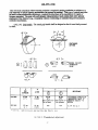
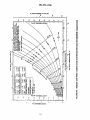
l.ix~ 0( 3ight -—------–—-
——— ———-—
Vertical and horimmta] visual field-—–-—————
—--——
---------
—--------
14
15
Relative position of scale marks. numerals, and pinters on circular dials------ 24
48
Rotary wkcmr switch -------------------------------------------------------Kc-v-npcratedswitch ----------------------------------------------------------------49
vi
I
#
M[L-STD-1472E
FIGURE
6
7
8
9
10
11
12
13
14
15
16
17
18
19
20
21
22
23-28
29
30
31
32
33
34
35
36
37
38
39
40
41
42
43
44
45
46
47
48
49
50
51
PAGE
Discrete Thumbwheel control----—— ---.----.. .. ...-- —------------------------- 51
Knobs —----- .... .. .------- .-. -..-— --- .---— —.--——--— ---- --- 53
——---. . -.-- ———.
---— ——-...
--.-54
Ganged k!lObS . .-— ——--—
————
Thumbwheel adjustment —-———
55
--.--—-~
cranks ---------------–---———
---------- ~—----.
-------------::
Pushbuttons (finger or hand operated) -------------------—
—----- --Foot operated switches –—----—
-------------------------::
Toggle switches -------------------------------------------------------------65
Legend switches-----------------------------------------------------------------67
Rocker switches -----------------------------------------------------------------—-—-- —--.---- ——-----.---—
----------- 68
Slide switches --—---—
Lever ----------------------------------------------------------------72
Isotonic joysticks ------------------------------------------------------------74
--—--— .—— —-. —--—.
-—----- —---- 76
Bali contmis———
-—-- -. -----——----------- .-—----- —---- --- -— 79
Pedals———
80
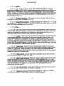
Ann, hand, and thumb-finger strength (5th percentile male data)
Leg strength at various knee and thigh angles (5th percentile male data) ----81
Not used
------—------------- 91
Anthropometric data for workspace-—------–-------—————
Standard console dimensions key ----–--–----------— ----------------------97
—--------- 98
Example of horizontal wraparound console---——-——————————
—------------ 98
Example of verticalkacked segments ----—------—---–-————
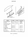
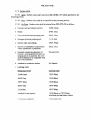
Type of structure in relation to angle of ascent -----——-—--—–——-;;
Stair dimnsiow ------------------------------------------------------—---1
00
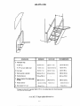
Stair-ladder dimensions------------——-—————
Fixed ladder dtimions--------------------------------------------------l
01
— . ...-. --- —------------- 103
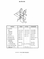
Whole body access opening —--. ------------...
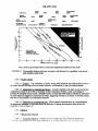
Effective tempeqture (ET) or corrected effective temperature (C.E.T) -----–-105
-----—— --------- 106
ventilation I’equlmmmts -.—-..—......-...—-——
Summer and winter comfort zmes and thermal tolerance for inhabkd
.—--——. —----—--- ---------- 107
———
~ts
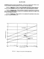
Pennissib)e &stance between a speaker and listeners for specified voice
—112
levels and ambient noise levels-----—---—-—--————
113
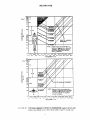
Range of accqtablc reverbmtion time -—-———--—--——-—--Vibration exposure criteria for longitudinal and transverse directions with
——.——-——
-- 114
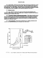
respect to body axis--------—— ----------The 90 percent motion sickness protection limits for exposure to vexy low
---–-———----------1 15
-~
~
/mn and hand awess dimensions — ------- ——-.-.--— — -----——-- 120
-k
Ofpldl fow CC)ditiortS for Table ma-----------.–-–-–-–.------;fi
SW rn,wl?,.:wn
.4?% .... .. ..... -..----- ..---.. -..---------------- —-----------.-———--—-—
—-.. -—----------- 132
Minimum han& a.
Anatomical limits on axhdly symmetrical ocular metal parts ---------------------- 143
Dimensions for vehicle operator’s seat------------—--------------––------------1 45
Recommended clearances around equipment operator’s station ----------------- ]46
TABI,E
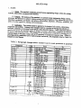
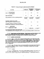
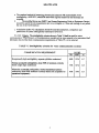
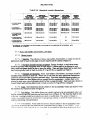
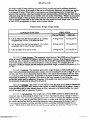
Paragraph changes where exclusive use by male personnel is specified -------Cu4L4g
oraiiibpl~
ibdkblw
ligk
-------
.-..,.
.
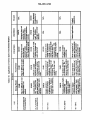
1
~?
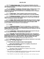
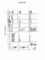
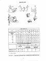
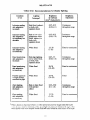
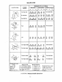
Application of various types of mechanical display s------------------------------ 21
/,\ll L;upaiculllg \;! @l&J
‘,..I ,.?
,“,.,., di:.~!:!:,:
,J.LI.L.lW
. .
----TO
Vll
,!.
.
..<l.”
...,,<
MIL-STD-1472E
PAGE
TABLE
v
VI
VII
VIII
Ix
x
XI
XII
XIII-XVIII
XIX
xx
XXI
XXI 1
XXIII
xxv
xxv
XXVI
XXVII
mvIII
XXIX
----Functional evaluation of audio signals ------------------------------------:
Intelligibility eritcria fbr voice communication SYSWrnS-—--——
------------Minimum, edge-to-edge separation distances for controls -------------------44
Advantages and disadvantages of various types of coding ----------------------- 45
Hmdwheels ---------------------------------------------------------------------------58
63
Keyboards ------------------------------------------------------------------------Push-pull contiols --------------------------------------------------------------------70
Label size versus luminance --------------------------------------------------------85
Not used
Anthropometric data for common working positions ---------------------------- 90
Standard console dimensions ------------------------------------------------96
Specific task illumination rqtiremenW ---------------------------------------------- 109
Recommendations for display lighting -------------------------------------------111
Design weight limits---------------------------------------------------------123
Horizontal push and pull forces exertable intermittently or for short periods
—-—-—-—-1 26
of time (male pemonnel) -—-———--——
--.
-----------.
--..
-.——.——
----------------128
Static muscle strength data
Typical fighting and existence loads (temperate zone) ----------------------------- 139
Recommended clearances around equipment operator’s station to
accommodate the 95th percentile soldier dressed in ktic ciothing -------- 146
164
Dialogue type VerSUSuser training and system resw~e---—--..----------system response time ---------------------------------------------------184
INDEX --------------------------------------------------CONCLUDING MATERIAL — —-—---
——
———
--—-—
-——-----–------1
188
98
MIL-STD-1472E
i.
SCOPE
1.1 Scope. This standard establib
general human engineering design criteria for rni]i~
systems, subsystems, equipment and facilities.
1.2 PurDose. The purpose of this standard is to present human engineering des~gn criteri%
principles, and practices to ac~:ve mis&on succms through integmti?n of the hmt? the system,
subsystem, equipment and faclhty, and aciueve effectiveness, sunphclv, ei%ciency, rehabiliu, and
safety of system operation, training, and maintewce.
i.3 Amiication. This standard shall be applied to the design of all systems, subsystem,
equipment and fmilities. Notig in this stantid shall be construd as limiting the selection of
hardware, materials, or procesws to the specific items descri~d herein. Unless othetiw stated in
specific provisiom, this standard applies to design of systems, subsystems, equipment and facilities
for use by both men and women. This standmd is not intended to be a criterion for limiting use of
materiel already in the field in areas such as lifl repetition or tempem~ expos~e time. Where the
proc~
=tivity ~bkhes
usc by & personnel exchsiveiy, the paragrap~ listed in Table I are
changed as noted *M.
ed
MIL-STD-1472E
1.4 Force limits. If it is known that an item is to be used by an already established military
occupational specialty, for which physical qualification requirements for entry into that speckdty are
also establish any discrepancy hetwem the force criteria of this standmd and the physical
qualification requirements shall be resolved in favor of the latter. in this even4 the least stringent
physical qualification requirement of all specialties which may opem*, ~@WPOI’LSUPPIY,
move, lift or otherwise maniptdate the item in the manner being considered, shail be used as a
mtiurn
&sign force limit. If such physical qualification requirements for entry into a specialty do
not cover the task covered herein, the criteria herein shall govern.
1.5 Manuf&cturinRtolerances. When manufacturing tolerances are not perceptible to the user,
this standard shall not be construed as preventing the use of components whose dimensions are within
a normfd rnanuhduring upper or lower knit tolerance of the dimensions specified herein.
2. APPLICABLE DOCUMENTS
2.1 General The documents listed in this section are specified in sections 3,4, and 5 of this
standard. This section does not include documents cited in other sections of this standard or
recmtunended for additional information or as examples. While every effort has been made to ensure
the completeness of this lis~ document users are cautioned that they must meet all specified
requirements documents cited in sections 3,4, and 5 of this standard, whether or not they are listed.
2.2 Government documents.
2.2.1 !%ecifications, standards. and handbooks The following specifications, standards, and
handbooks form a part of this document to the extent specified herein. Unless otherwise specim the
issues of these documents are those W in the issue of the Department of Defense Index of
Specifications and Standards (DoDISS) and supplement thereto, cited in the solicitation (see 6.2).
SPECIFICATIONS
DEPARTMENT OF DEFENSE
MIL-M-18012
MIL-C-25050
hkkings for Arcrew Station Displays, De&i and
Configuration of
Colors, Aeronautical Lights and Lighting
EqtipmenL General Specification for
STANDARDS
FEDERAL
FED-STD-595
-
Colors
DEPARTMENT OF DEFENSE
MII.-STW28O
MIL-STD-783
MIL-S-ID]2W
MJL-s”rD- 1474
MIL-STD-1787
Definitions of Item Levels, Item interchangeability,
Models, and other related Terms
Legends for Use in Aircrew Stations and on
Airkmc Equipment
Keyboard Arrangements
N&e Limits
Aircraft Display Symbolog)
-
MIL-STD-1472E
HANDBOOKS
DEPARTMENT OF DEFENSE
MIL-HDBK-454
DOD-HDBK-743
MIL-HI)BK-759
MIL-HDBK-1473
MIL-HDBK-1908
-
General Guidelines for Electronic Equipment
Anthropometry of US Military Personnel
Human Factors Engineering Design for Army Materiel
Standard General Requirements for Color and Marking
Definitions of Human Factors Terms
(Unless otierwise indicated, copies of federal and miiitary specifications, standards, and
handbooks are available from the Standardization Documents Order desk 700 Robbins Avenue, Bidg
4D, Philadelphia, PA 191 11-5094.)
2,2.2 Other Government documents, drawinszs,and publications. The following other
Government documents, drawings. and publications form a part of this document to the extent
specified herein. Unless otherwise specified, the issues are those cited in the solicitation.
29CFR 1910
-
Occupational Safety and Health Standards
(Copies of specifications, standards, and other publications rquirtxi by contractors in connection
with specific acquisition Ii.mctionsshould be obtained from the contracting activity or as directed by the
contracting officer.)
2.3 Non-government publications. The following document(s) form a part of this document to
the extent specified herein. Unless otherwise specifi@ the issues of the document which are DoD
adopted are those listed in the issue of the DoDISS cited in the solicitation. Unless otherwise
specifi~ the issues of these documents not listed in the DoDISS are the issues of the documents cited
in the solicitation (see 6.2).
AMERICAN CONFERENCE OF GOVERNMENTAL INDUSTRIAL HYGIENISTS (ACGIH)
ACGIH TLV
-
Threshold Limit Values
(Application for copies shouid be addressed to the ACGIH, 1014 Broadway, Cincimati, OH
45202.)
AMERICAN NATIONAL STANDARDS INSTITUTE (ANSI)
ANSI S1.1
ANSI S1.4
ANSI S1.6
ANSI S3,2
ANSI S3.5
Acoustical Terminology
Sound Laei Maera, Spwificatim fa(DoD Adopted)
Preferred Frequencies and Band Numbers for Acoustical
Measurement (DoD Adopted)
Monosyllabic Word Intelligibility. Method for
Measurement of(DoD Adopted)
Articulation I.nc& Method fix the Calculation of (DoD
Adopted’)
-
(Apphcanon for copws should be addressed to the American National Maniiards Insmute. inc..
14~(1 I+rnartwa:’ New York
NY lf~ol 8 )
MIL-STD-1472E
AMERICAN SOCIETY FOR TESTING AND lvf/+TERIALS(ASTM)
ASTM E 380
-
ASTMF 1166
-
Standard Practice for Use of the International System of
Units (S1)(The Modernized Metric System) (DoD Adopted)
Standard practice for Human Engheering des&n Criteria
for Marine systems equipment and fmilities (DoD Adopted)
(Application for copies should be addressed to the American Society for Testing and Materials,
100 Barr Harbor Drive, West Conshohoeken, PA 19428-2959.)
HUW
FACTORS AND ERGONOMICS SOCIETY (HFES)
ANSI/HFS 100 -
Ameriean National Standard for Human Factors
Engineering of Visual Display Terminal Workstations
(DoD Adopted)
(Application for copies should be addressed to the Human Factors and Ergonomics Society,
Inc., P.O. Box 1369, Santa Monicz CA 90406.)
INTERNATIONAL ORGANIZATION FOR STANDARDIZATION (ISO)
1S02631
-
Guide to the Evaluation of Human Exposure to Whole
Body Vibration
(AppIieation for copies should be addresd
1430 Broadway, New York, NY 10018.)
to the American National Standards Institute, inc.,
SOCIETY OF AUTOMOTIVE ENGINEERS (SAE)
SAE .J925
-
Minimum Access Dimensions for Construction and
Imhmrial Mwhinmy (DoD Adopted)
(Appktion for copies should be addmscd to the Society of Automotive Engineers, 400
Commonwealth Drive, Warrendak, PA 15096400 i.)
(Non-Government standards and other publications are normally available from the organizations
that prepare or distribute the documents. These documents also maybe available in or through
libraries or other informational services.)
2.4 Order of mecedence. In the event of a conflict between the text of this document ad the
references cited hereb the text of this doeurnent takes pree.edenee. Nothing in this document
however, supersedes applicable laws and regulations unless a speeific exemption has been obtained.
3. DEFINITIONS
Unless otherwise specified. terms are defined in accordance with MIL-HDBK-1908.
4, GETWRA1, REQI JIREMENTS
4. i Obiextives. Military sys(cms, equipment and facilities shall provide work environments
whkh Lwr dkii~ c pwduru,
Lvcdipatterns, and pcrsonnc! ~fcty and hcdth, and which minimi?r
factors which degrade human performance or increase error. Design induced requirements for
upcrolw ‘s:urkluud,UCCIW2C;
. ~.jlll,,,(,~n$tr~ill~,nle!llfi~~rncewinu, and (’{)rnm~ttli[’:]tion shrill not rx(.(xd
4
M1l.-STD-1472E
operator capabilities. Design shall also minimize personnel and training requirements witlin the limits
of time, cost, and performance trade-offs.
4.2 Standardiition. Qmtro!s, displays, marking, coding, labeling, and arrangement schemes
(equipment and panel layout) shall be uniform for common functions of all equipment. Criterion for
selecting off-the-shelf cornrnmial or Government equipment shall be the degree to which the
equipment confoxmsto this standard. Where off-the-shelf equipment requires modification in order to
interface with other equipment, the modification shall be designed to comply with the criteria herein.
Redesign of off-the-shelf equipment must have the approval of the procuring activity.
4.3 Function abcation. Design shall reflect allocation of functions to persomel, equipmenL
and personnel-equipment combinations to achieve:
a. required sensitivity, precision, time, and safety,
b. required reliability of system performance,
c. minimum number and level of skills of personnel required to operate and maintain the
system, and
d. required performance in a cost-effective manner.
4.4 Human en~ineerimzdesire. Design shall reflect human engineering, life support, and
biomedical factors that affixt human petiorrnance, including, when applicable:
a. satisfactory atmospheric conditions including composition pressure, temperature and
humidity, including safeguards against uncontrolled variability beyond acceptable hits;
b. range of acoustic noise, vibratio% acceleration, shock, blast, and impact forces and
safeguards against uncontrolled variability beyond safe limits;
c. protection fim thermal, toxicobgical, radidogical, mechanical, electrical, electromagnetic,
pyrotechnic, visual, and other hazmds;
d. adequate space for personnel, their equipment and * volume for the movements and
activities they are required to perfbrm during operation and maintenance tasks under both
normai and emergency condib,
e. adequate physical, visual, auditory, and other communication links between pemonnd, ad
bemveenpersonnel and their equipmen~ under both normal and emergency conditions;
f.
=yw—-~-~
nwkuwue
worx
e@pmenb controls, and
g. provisions for ensuring safe, efficient taak performance under reduced and eievated
gravdatbrud b=
with safkguwds against @jury, equipment d~age ~d dis~rientation;
h. adeq=wml;or
and !
artificial illumination for the performance of operation, control, training,
i. safe and adequate passageways, hatches, ladders, stmrwzrys,piattorms, inches, and other
provisions for ingress. egress. and passage under normal. adverse, and emergency
conditions:
5
MIL-STD-1472E
j
provision of acceptable personnel accommodations including body support and restraint,
seating, rest, and sustenance, i.e., oxygen, food, water, and waste management.
k, provision of non-restrictive personal life support and protective equipment;
1. provisions for minimizing psychophysiological stress effects of mission duration and fatigue;
m. design features to assure rapidity, safety, ease and economy of operation and maintenance in
normal, adverse and emergency maintenance environments;
n. satisfactory remote handling provisions and tools;
o. adequate emergency systems for contingency management escape, survival and rescue; and
P- compatibility of the desig~ location and layout of controls, displays, workspaces,
maintenance accesses, stowage provisions, passenger compartments, allocated tasks, and
control movements with the clothing and persoml equipment to be worn by personnel
operating, riding in, or maintaining militmy systems or equipment.
safe design.
4.5 Fail _--—-. A fail safe desire shall be movided in those areas where failure can cause
catastrophe through damage to equipmenL injury to personnel, or inadvertent operation of”critical
equipment.
-“
.
-..
.
4.6 Simplicity of desire The equipment shall represent the simplest design consistent with
functional requirements and expected service conditions. It shall be capable of beii operated,
maintained, and repakd in its operational environment by personnel with a minimum of training.
4.7 Interaction. The design of the system shall reflect the interaction requirements of crew
served equipment.
4.8 Safety. Design shall reflect applicable system and personnel safety factors, including
of tbe Sym
prticldarly under
minim&@ potential iwmanerrorintheoperationand mainMMm
the conditions of al- battle stress, or other emergency or non-routine conditions.
4.9 Rumwirwss. Systems and equipment shall be sticiently rugged to withstand handling in
the field during operation, maintenance, supply, and transport within the environmental limits specified
for those conditions in the applicable hardware or system specification.
4,10 Design for NBC survivability. As applicable, equipment design sha!l be compatible with
NBC protection and shall permit performance of mission+ssential operations, communications,
maintenance. resupply artd d~
tasks by suitably clothed, trained, and acel~
personnel for the survival periods and NBC environments required by the system. Equipment design
shall also facilitate NBC hardness surveillance and shall minimize susceptibility to reduction of
inherent NBC hardness as a result of operator- or maintainer-induced errorsldamage, i.e.:
a. NBC hardness shall be eady verifiable by maintenance per-some] before and after
maintenance actions (hardness surveillance).
h. NBC hardness shali not bc degraded \vhcn rouunc (schcdulcd) and corrcctwc (unschcdulcd )
mnintcnmcr w? pmi’nmml
-...-——-.
MIL-STD-1472E
c. Maintenance of the equipment’s inherent NBC hardness shall not be dependent on
maintenance personnel expertise and critical alignmentdmaintenance actions.
4.11 Desire for electroma~netic ~ulse (EMP) hardening. As applicable, equipment design shall
be compatible with EMP hardening requirements, including personal amornmodations such as EMPhardened electrical power outlets and antenna lead-ins within EMP-hardened fmilities or spaces.
Access shall be provided to EMP-hardened facilities or spaces without the need to open doors or
hatches which form part of an electromagnetic barrier protecting the space. Items such as surge
mestors, terminal protection devices, and filters, which form part of an electromagnetic bamier for
protection against EMP effects, shall be accessible.
MIL-STD-]472E
5. DETAILED REQUIREMENTS
5.1 Control-disdaY intimation.
5.1.1 General criteria.
5.1.1.1 Relationship. The relationships of a control to its associated display and the display to
the control shall be immediately apparent and unambiguous to the operator. A mttml should be
located adjacent to (normally under or to the right of) its associated display and positioned so that
neither the control nor the hand normally used for setting the control will obscure the display.
5.1.1.2 Elm
Contrcddisplay relationships shall be apparent through proximity, sWty
groupings, coding, tlaming, labeling, and similar techniques.
of
5.1.1.3 Comtkxity and umcision. The eotnplexity and preeision required for control
manipulation and display monitoring shd be consistent with the precision required of the system.
Control-display complexity and precision shall not exceed the operator’s capability to discriminate
display detail or manipulate controls (in terms of manual dexter@, coordination or reaction time) under
the dynamic conditions and environment in which human performance is expected to occur.
5.1.1.4 Feedback Feedback of control response adequaey shall be provided quickly.
Feedback shall be intrinsic or extrinsic to ind]cate (without ambiguity, uncertainty, or error) to the
operator that the control is properly actuated, that the desired response is achievei and when the
desired response is complete. Critical control fictions, such as those entered by keyboard, shall
provide f-k
to the opemtor prior to entry to erwum that the keyrxl eng is erroriess and the one
that the ojmitor desires to enter,
5.1.1.5 Ilhuninat.ion. Adjustable illuminabn shall be provided for visual disp~ays(including
display, control, and panel labels and eriticid maddngs) that must be read under darkened conditions.
5.1.1.6 %mhaneousaecess. lfmomti~~-bmwkvetid-u~~
a group of controls or displays to ensure proper functioning of a system or subsystenL the operator
asaigxd to control and monitor that finction or group of related fbnctions shall have physied and
visual ~
to all controls, displays, and communication capability neeessary to adequately pcrfonn
assigned tasks.
5.1.2 Position relationships.
5.1.2.1 Functiodmwping.
Fudoadly dafaduxtdsaad
dispiaysshd
eaeh other and arranged in fictional group%e.g., power, status, test.
lbekakddoseto
5.1.2.1.1 Functional ~rou~ arrarwement.
5.1.2 .1.1.1 Sequence Functional groups of controls and displays shall be located to provide
for left-to-right (prefemed) or top-to-bottom order of use, or both.
5.1.2 .1.1.2 Access Providing that the integrity of grouping by fimction and sequence is not
compromised, the more frequently used groups and the most im rtant groups should be located in
areas of easiest access (’rmtrol-diy-ky groups required solely rw maintenance purposes shall be
located in pwitions providing a Ies.serdegree of access relatwe to operating groups.
5,1 ‘). 1.1.3 ~~f.ti~nal ~~~~ m~~~
Functional groups may be set apart by outlining with
contrasting lines which wmplctcly cnwmpa.ss the grwps. Where such coding is specitied h)’the
procurinp activity. nnd wherr :rav pmels are used. noncriltcal functional groups (i.e.. those not
8
I
MIL-STD-1472E
associated with emergency operations) shall be outlined with a 1.5 mm (1/16 in) black border (27038
of FED-STD-595), and those involving emergency or extremely critical operations shall be outlined
with a 5 mm (3/16 in) red border(21136 of FED-STD-595). t% an alternate method, contrasdng color
pads or patches maybe used to designate both critical and noncritical functional areas, subject to prior
approval by the procuring activity. When red compartment Ii ting is ~
an
orange-yellow (23538 of FED-STD-595) and Nack (27038 o FFED-STD-595) striped border shall be
used to outline I%nctionalgroups involving emergency or extremely critical operations. Controldisplay areas in aimra!l crew stations shall be delineated in accmdance with MIL-M-18012.
5.1.2 .1.1.4 Consistency. Location of recurring functional groups and individual items shall be
similar from panel to panel. Mirror image amngements shall not be used.
5.1.2.2 Location and arran~ement- If an operator must use many controls and displays, they
shall be located and turanged to aid in i&nti@ing the controls used with each display, the equipment
component al%eted by each control, and the equipment component described by each display.
5.1.2.3 Armuzement within mouDs. Controls and displays within fictional
hated according to operational sequence or funetio~ or both.
groups shall be
5.1.2.3.1 Lefl-to+kht arrangement. If controls must be arranged in fewer rows than displays,
controls affizting the top row of displays shall be positioned at the left; controls affecting the second
row of displays shall be placed immediately to the right of these, etc.
5.1.2,3.2 Vertical and horizontal arraYs. If a horizontal row of displays must be associated with
vertieaicolurnn ofeontrds or vice vthe left item inthehorimntd array shall correspond to the
top item in the vertical array, etc. However, this type of arrangement should be avoided.
a
5.1.2.3,3 Simultarwus use. To maintain Je@bfity and avoid parallax errors a visual display
that must be monitomd while a related conlrol is manipulated shall be located so that the operator is not
required to observe the display from an extreme visual angle.
5.1.2.3.4 MuMvIeclkmlaYs. If manipulating one control requires reading of several display%
the control shall be placed as near as possible to the related displays and preferably beneath the middle
of the displays, but not so as to obscure displays when manipulating the control.
5.1.2.3.5 Combined control. Separate displays that are aflketed by a combined control (e.g.,
concentricity an ed knobs) shall be arranged fium left to right with the combined control underneath
the center of t&e splays, but not so as to obscure displays when manipulating the control.
5.1.2.3.6 Scoara mnels. When related controis and displays must be located on separate
pand$atadb@lanek%wn$ed@pmxim@
the same angle @a@e to the operator, tie ~n~l
Poaitimts on one panel shall correspond to the associated display positions on the other panel. The two
panels shall not be mounted facing each other.
5.1.2.3.7 Component ErOUDSWhen a group of equipment components has the same fiction,
the related control and di lay positions shall be oriented to corm pond to those of the controlled and
monitored components. T or example, the position of aircraft engine controls sha!! be oriented fbr an
opemtor facing the normal direction of vehicle movement.)
5.1.2.3.8 ~mer~ency use. Emergency di lays and controls shall be located where they can be
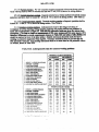
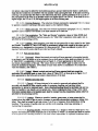
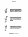
scum’ldleaohed%thcmtdeiey te,g.,-.
*.*
Xl” ~tiL~kuwWinc
&.
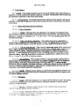
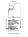
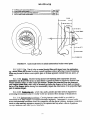
of sight (see Figure 1), emergency control close to its related warning display, or use of the nearest
dwdiiabk Luhi iii ils nomikd qxxating position).
,,,
, ,.,,. .
?,,,..
MIL-STD-1472E
5.1.3 Movement relationship.m
5.1.3.1 Lackofambitity.
Display indicators shall clearly and unambiguously dkect and gui&
the appropriate cmntrolresponse. The response of a display to control movements shall be consistent,
predictable, and compatible with the operatofs expectations.
5.1.3.2 Tie lag. The time lag between system response to a control input and display
presentation of that response shall be minimi@ consistent with safe and effective system operation.
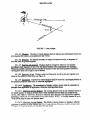
5.1.3.3 Movim-po inter circular scales. Clockwise movement of a rotary control or forward,
upward or tightwad movement of a linear control shall produce a clockwise movement of circular
scale pointers and an increase in the magnitude of the setting.
5.1.3.4 Movimz-tminter linear scales. Clockwise movement of a rotary control or forward,
upward, or rightward movement of a iinear control shall produoe a movement up or to the right for
horizmtal and vertical scale pointers and an increase in the magnitude of the reading.
5.1.3.5 Fixed-pointer circular scale. Displays with moving scales and fixed pointers or cursors
should be avoided. When circular, fixed-pointer, moving-scale indicators are necessary, clockwise
movement of a rotary control or forward, upwar~ or nghtward movement of a linear control shall
normally produce a counterclockwise movement of tbe scale and an increase in the magnitude of the
reading.
5.1.3.6 Fixed winter linear scale. When use of vertical or horizontal fixed-pointer, movingscale indicators is necessq, clockwise movement of an associated rotary control or forward, upward,
or rightward movement of a linear contxolshall normally produce a movement of the scale down or to
the ieil and an increase in the magnitude of the reading.
5.1.3.7 Direct iinkatze. When a control and display are dircctIy linked (e.g., radio frequency
selector and station pointer), a rotary control shall be used if the indicator moves through an arc of
more than 18V’.If the indicator moves through an arc of Iessthmt 180”,a iinearcontrol may be@
pxovkkd b path of control movement parallels the average path of the indicator movement and the
indicator and c4xttr01move in the same relative direction.
5.1.3.8 Common plane. Direction of control movements shall be consistent with related
movements of associated displays, equipment components, or vehicles.
5.1.3.9 Parallel movement. Direction-of-movement relationships shall be adhered to when
contm! and display me pamlld in line of rnovenxxL
5.1.3.10When control-display relationships Specifkd herein cannot be adhered to,
controls shall be clearly labeled (see para 5.5) to indicate the direction of control movement requhed.
5.1.3.11 Movement direction. When a rotary control and a linear dispiay are in the same plane,
the part of the control adjacent to the display shall move in the same direction as the moving part of the
display.
5.1.4 ControVdisPlavmovement ratio.
Minimization of time, Control/display ratios for coritinuous adjustment contmis shaii
w MMAGJAMI
i.wdml moscmmts (skwiqg apd fine adjusting), corts+wcnt
with display size, tolerance requirements, viewing distance, and time delays.
5.1.4,1
nmirnme the time mquiA
MIL-STD-1472E
5.1.4.2 Ramze of disulay movement. When a wide range of display element movement is
required, small movement of the control sha[l yield a large movement of the display element. When a
small range of display movement is required, a large movement of the control shall result in small
movement of the display, consistent with fml accuracy required.
5.1.4.3 Knob, coarse setting. When a knob is provided for making coarse display element
settings on linear scales- 0.4 to 2.5 mm (0.016 to 0.100 in) tolerance-approximately
150 mm (6 in)
display element movement shall be provided for one complete turn of the knob.
5.1.4.4 Knob, fine setting. For fine setting on linear scales4.2
to 0.4 mm (0.008 to 0.016 in)
tolerance-25 to 50 mm (1 to 2 in) of display element movement shall be provided for one complete
turn of the knob.
5.1.4,5 Bracketing. When bracketing is used to locate a maximum or minimum rather than a
specific value (e.g., tuning a transmitter), the control knob shall swing through an arc of not less than
10° nor more than 30” on either side of the target value in order to make the peak or dip associated with
that value clearly noticeabk.
5.1.4.6 Lever. coarse setting. When a lever is provided for coarse setting~.4
to 2.5 mm
(0.016 to 0.100 in) tolerance-one unit of dispiay element movement shall be induced by three units of
lever movement.
5.1.4.7 Lever, twodimensiond setting. When a lever is provided to make settings in two
dimensions to coarse tolerances-2.5 mm (O.1 in~ne
unit of display element movement shall be
induced by two and one-half units of lever movement.
5.1.4.8 Counter ccmtrol/display ratio. One revolution of a counter knob should produce
approximately 50 counts (i.e., the righthand drum rotates five times).
5.1.4.9 Visual Display Terminals (VDTS). See 5.16.
II
\
MIL-STD- 1472E
5.2 Visual displays.
5.2.1 GeneraL Visual displays should be used to provide the operator with a ckar inckation of
equipment or system conditions fm opemtion under any eventuality eolnm~te
with the operational
and maintenance philosophy of the system under design.
5.2.1.1 [email protected]. An akrtinghming
display shall provide the opemtor with a greater
probability of detecting the triggering condition than normal observation would provide in the absence
of the display.
5.2.1.2
DisdaY illumination and light distribution
5.2.1 .2.1 Display illumination.
5.2.1.2. i. 1 Normal. When maximum dark adaptation is not requid
low brightness white
light (preferably integral and adjustable as appropriate) shall be used; however, when maximum dark
adaptation is required, low 1urninance [0.07 -0.35 cd/m2 (0.02 -0.10 fL)] red light (greater than 620
nm) shall be provided.
5.2.1 .2.1.2 Nitit vision device cotma tibiiity. Where night visi(m device compatibility is
required, display ihmination edor other than red may be usd. The lighting shall be continuously
variable to the fuII OFF position. In the OFF positio~ no cunent shall flow through the lamps.
5.2.1 .2.1.3 Field usepanel dimming. WhexIcontrol or annunciator panels wiil be viewed out of
doom~ti~mm
~l~m~h~ti-aag~mml
isatits
extreme ckdcwiae rotation. Maximum ilhmi.nation is that mquimd by Tabks ~
and XXI, as
applicable. No panel U@ting cument shall flow when the dimming ezmtrolis at its extreme counterclockwise rotation. Panel I@ levels shall be ecmtinuousty variable fbm 0.1 @
(0.03 fL) near
OFF {o3.5 cd/rn2 (1 fL) at 50?? of clockwise rotation.
5.2.1.2.2 ~hzht di5txibUtiOQ.Where multiple displays are group together, lighting shall be
I such that the mean indicator lummmees of any two instruments
balanced across the’
~F than ~ V.across the range of fidl ON to full OFF. To ensure that light
shall not diffkr ~ mom
the ratio of the standad
distribution Within an integrally ilhminatd instmnm t is sufficiently unifii
deviation of indbtor ekmcnt lumbnces to mean indicator lumimmce shall be not more than 0.25,
using eight or more equally speed test measmments.
5.2.1 .2.3 batzaaL Sufkient cxmkast shallbe provided between all displayed information and
the display background to ensure that the required information can be perceived by the operator under
all e~cted lighti~ conditions.
5.2.1.3
hfbmMtiOIL
5,2.1.3. ] ~Qntent Info~atj~n di ]ayed to ~ ~~~t~r shall & sufficient to allow the operator
10perfm-mthe intended mission. but shall%2 limited to information necessary to ~rform specific
actions or to make decisions.
< 7 I ~ ? pwciqi(~n
info~ntion
shtil! he (ii~plaved
,.
rqulrcd for specific operator actions or decisions.
onlv within the
limits and precision
MI I.-STD-1472E
5.2.1.3.4. Redundancy. Redundant information shall not be displayed to a single operator
unless it is requmed to achieve specified reliability.
5.2.1 .3,5 Combininjzo matorhtmintainer information. Operator and maintainer information
shall not be combined in a single display unless the information conten~ forma~ and timeliness
qpofi tie needs of both users.
5.2.1 .3.6 Display failure clarity. Failure of a display or other parts of the display subsystem
shall be immediately apparent to the operator.
5.2.1 .3.7 Dis~lav subwstem failure. Failure of the display subsystem shall not cause a fhilure
in the equipment associated with the display.
5.2.1 .3.8 Unrelated markirws. Trademarks and company names or other similar markings not
related to the panel function shall not be displayed on the panel face.
5.2.1 .3.9 Duzition. Signals and infiion
shall be displayed long enough for reliable
detection under expected operator workload and operational environment.
5.2.1.3.10 Timeliness. Displays requiring refished information (e.g., cathode ray tube
displays, head-up displays) shall be updated in a synchronous manner, where possible, and be
refished at a rate required by personnel in the normal operating or servicing mode.
5.2.1.3.11 Advisow and alerting. Devices displaying simultaneous and integrated information
(e.g., multifunction displays, cathode ray tube displays, head-up displays, collimated displays) shall
alert or cue operating personnel to information that becomes critical within the display.
5.2.1.3.12 NBCcon@ninati on. As applicable, display characteristics (e.g., legibility) shall be
compatible with viewing while wearing an NBC protective mask. Disp!ays or indicators that show the
presence of NBC agents shall also show when such agent concentrations decrease to safe levels.
5.2.1.3.13 Numeric di~ital disda~s. Numeric digital displays should be used when precision
of displayed information is importan$ but shall not be used as the oniy display of information when
the pattern of variation is important for accurate perception or when rapid or slow digital display rates
inhibit accurate perception.
5.2.1.4 Location and arrangement.
5.2.1 .4.1 Lwdi~
Displays shal! be located and designed so that they may be read to the
required degree of accuracy by personnel in their normal opemting or servicing positions without need
to assume uncomfortable, awkward, or unsafe postures.
5.2.1 .4.2 Access Visual displays Should be visually accessible without resorting to use of
ladders, flashlights, or other special equipment in order to read the display.
5.2.1 .4.3 @en@tion. Display faces shall be perpendicular to the operator’s normal line of sight
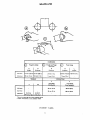
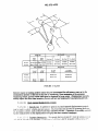
whenever feasible and sMI! be not less ‘l!tan45” fiwrnthe norm! line of sight (see Figure 1). Parallax
shall be minimized.
5.2. 1.4.4 Reflection. Displays shall be constructed. arranged, and mounted to prevent
wblkikn+ J idkwui.w ti4JJ k L dhiin
J k ambbt iU& ‘‘km f.raialUCLli@+
cover. Reflection of instruments and consoles in windshields and other enclosures shall be avoided.
!i’lw~exiar~, ;tihni+ uw (suc!~as W of shields and fihcrs) shall be Cnlplu)’ cd W Gmsur: that Sj’stun
pwfoml;mw wiII not h dcf!rwld
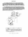
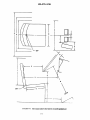
MIIATD-1472E
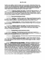
FImRE
1. Lines of sight
5.2.1.4.S ~.
Vibmtion of *u~ ~P~aYSs~
level required for mission accomplishment (see 5.8.4.2).
not d~~de ~
@~*
~low’ tie
5.2.1.4.6 ~.
All displays necessary to support an operator activity or sequence of
activities, shall be grouped together.
. Displays sha!l be arranged in relation to one another
5.2.1.4.7 J%nction and ~
accordiig to thtdr se uence of useorthefinotionalrelationsof the catthey R3presenL
Whenever possible, L“ lays shall be arranged in sequence within functional groups to provide a
viewirtg flow fkom left-to-right or top-to-bottom.
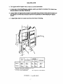
Vof U& Displays used most frequently should be grouped together and
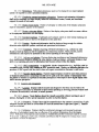
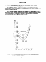
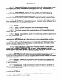
5.2.1.4.8 ~ue
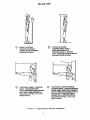
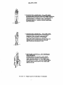
placed in the optimum%w3 zone (see Figure 2).
521.4.9 ~.
Important or critical dis lays shaXbe located in a prhdleged position in
the optimum projected visual zone or otherwise hig & “ hted.
@@e
The arrangement of displays within a system shall be consistent in
5.2.1.4.10 ~
ffom appl.i~ffon to kpplicatiom within the limits specified herein.
The viewing distance from the eye mfcrencc point of
5.2.1.4.11 Jvlaximum viewi~
the seated operator to displays located c!ose & their associated controls shall not exoeed 64 an
(25 in). (See Table I.) Otherwise, there is no maximum limit other than that imposed by legibility
limitations, which shall be compensated for by proper design. NOTE A viewing distan~ of up to
76 cm (30 in) maybe used with ejection seats.
5.2.1.4.12 JWnimum view~,
The effective viewing distance to displays, with the
exception of cathode Iay tube displays (W 5.2.4.2) and colhitcd dispk)’s, shall be not less lhan
~qo mm (]? jn) and prp,fcrably not less thnn 510 mrn {2~in)
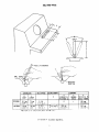
MIL-STD-1472E
16° WTIMUM
16°OPTIMUM
#
o
& MAXIMUM
‘~”’”””
~~;
EYE ROTATION
0° OPTIMUM
d
d’
MAXIMUM
MAXIMUM
\~
07’””
@~
35? MAXIMUM
HEAD ROTATION
l& OPTIMUM
16°OPTIMUM
90° MAXIMUM
/
(
l!f OPTIMUM
~
9!# MAxrMuM
c‘
S& MAXIMUM
‘“
(
‘o~%
%@r
Q~E
Ck=’JK
I
15°OPTIMUM
HEADANDEYEROTATION
MIL-STI.)-!472E
5.2.1.4.13 Aircrew station simmls, Important or frequently used pilot or co-pilot station
displays shall be placed in the prime visual signal area (PVSA) (see MIL-HDBK- 1908) or otherwise
highlighted. If a large number of important and frequently used displays exists, important displays
shall be the higher priority for placement in the PVSA. Criteria appearing ekwhere in this section do
not apply to pilot and co-pilot stations (see 5.14.2.1); however, human engineering design for other
members of the crew who occupy positions in the air vehicle other than on the fight deck(such as in
multi-engined specialized aircraft) shall be in accordance with the criteria herein.
5.2.1.5 Coding.
5.2,1 .5.1 Objectives. Coding shall be used to facilitate discriminating between individual
displays, identifying functionally related displays, recognizing the relationship between displays, and
identi~ing critical information within a display, and to preserve conventional practices and
arrangements for warning and alerting systems.
5.2.1 .5.2 Techniques. Displays shall be coded by color, size, Ioeation, shape, or flash, as
applicable.
5.2.1.5.3 $tandardizuion. All coding within the system shall be uniform and shall be
established by agreement with the procuring activity.
5.2.1 .5.4 Mcrew Display Svmbolo~y. SymboIogy for Aircrew displays shall be in accordance
with MIL-STD-1787.
5.2.2 Transiliuminated disdavs.
5.2.2.1 General General types of tramilluminated displays that may be used include:
a. single- and multiple-legend lights that present information as words, numbers, symbols, and
abbreviations,
b, simple indicator lights, and
c. transiihuninated panel assemblies thatpresent qualitative status or system readiness
information.
5.2.2.1.1 ~.
TransiIluminated displays should be used to provide qualitative information to
the operator requiring either an immediate reaction by the operator, or to draw attention to an important
system status. Such displays may also be used occasionally for maintenance and adjustment
functions,
5.2.2.1.2 Euuioment reswnse. Lights, including those used in illuminated push buttons, shall
display equipment response and not merely control position.
5.2.2. !.3 lnfcmnmrcm. Lights and rchsted m&atOrs shall be Ud q.mingiy and skdi &@&y
only that infbrrnation necesstuy for effective system operation.
5.2.2.1.4 Positive feedback. Changes in display status shall signify changes in functional status
rather thanmtrkwof eont?miaottmtmnuicme. Theoimemm orioe@ofasi&ud orv&wd~
Adi
not be used 10denote a “malfunction,” “no-go,” or “out-of-tolerance” condition; however, the absence
of a “power on” signal or visual indication may be used to indicate a “power off’ condition for
operational displays, but not for rnamtenancc displays. the absence or loss ot a sIgnd or visual
f-nrf~ifion
IInless
the S(nttl<
or
indication MU m h WCC!
to Mime n “mvh’”
. nr “in ttn!rr~nry”
~il(]ti~n light filamenl and it$msociated circuitry can hc easily tested by the operator and operator
~~,!l!~;>t;l
JII,)( .II(’htJ\Jf.I\Isii n(lf Iim(> critic;ll
10
MIL-STD-1472E
5.2.2.1.5 Grouping. Master caution, master warning, master advisory and summation lights
used to indicate the condition of an entire subsystem shall be set apart from the lights which show the
status of the subsystem components, except as rquid
by 5.2,2.1.8.
5.2.2.1.6 Location. When a transilluminated indicator is associated with a control, the indicator
light shall be located so that it can be associated with the control without emor and shall be visible to
the operator during control operation.
5.2.2.1.7 Location, critical functions. For critical functions, indicators shall be located within
15° of the operator’s normal line of sight (see Figure 2). Warning lights shall be an integral part of, or
located adjacent to, the lever, switch, or other control by which the operator is to take action.
5.2.2.1.8 Maintenance dhmlays. indicator lights used solely for maintenance and adjustment
shall be covered or non-visible during normal equipment operation, but shall be readily accessible
when required.
5.2.2.1.9 Lum@mx. The luminance of &anSillunmated
“
displays sMI be compatible with the
expected ambient illumimmce, and shall be not less than 10% greater than the sumounding luminance.
Where glare must be reduced, the hrninance of transill unmated
“
displays should be not more than
300% of the sumound.ing luminance.
5.2.2.1.10 Luminance control. When displays will be used under varied ambient illuminance, a
control shall be provided. The range of the control shall permit the displays to be kgible
under all expected ambient illumimmce. The control shall be capable of providing multiple step or
continuously variable illumination. Dimming to full OFF may be provided in non+xiticaJ opemtions,
buttiti&ti
tiM~tfduw~
onati_mtild
tiffl@_rfd~s,
i.e., failure to detector perform a critical step in an operation.
dimming
5.2.2,1.11 False indication or obscuration, Director reflected light shall not make indicatom
appear illuminated when they are not, or appear extinguished when they are illuminated. self-reflection
shall be minhizd wFW=~
“ Ofbdisplqwithmqmctto
lheobaemr.
. .
. .
5.2.2.1.12 ~trast
lthtn b mcllcator The lumimmce contrast (See MIL-HDBK- 1908)
within the indicator shaU bwnot less than 2.0. “Thisrquimment does not apply to special displays
spczificaliy designed for kgibility in sunlight. For low ambient illumination applications, this ratio
should be not less than 9.0, with the background luminance less than the figure luminance.
5.2.2.1.13 Lam nxhudancy. Incandescent light sourws shall use dual lamps or lamps with
two fihtrnents. When one fiknent or btdb faik, t.iwintensity of the @t Sh~ decreuse 9ttff_iCtiy to
indicate the need for lamp replacement, but not so much as to degrade operator performance.
Wlm indicator Aigbtsusing uandmemt bulbs aminstakdona
5.2.2.1.14 hwtuting
control panel, a master light tesi control shall be incorporated. When appropriate, the capability to
simultaneously test all control panels may be provided. Pan+ COmining three or *
lights may
incqomte individual pruss-to+est bulb testing, The total indkator circuit should be capable of being
testd. KdarkAa@a&imis a factar, a mans fot reduc~ total indiw
ijght brightness duriqg test
operation shall be provided,
~
> > 115 LUrnDl’e!wwd, methd.
.. -<-.
Whtwe fw!+swe, A&!i b twwwkie
from the front of the clis kiv panel. The proccdum. for knp removal and repkement
A
twpkwldc
shall not require
the use of tools and sha f1be easily and rapidly accomplished.
5.2.2.1.1 G LamP removal, safety. Display circuit design shall pennil lamp removal and
power is applied withw causing Iailure of indicator circuit components {N
It~pl~lrenten(whIk
MIIXTD-1472E
imposing personnel safety hazards.
5.2.2.1.17 Indicator covers. If the design of legend screen or indicator covers does not prevent
inadvertent interchange, a means shall be provided for checking the covers after installation to ensure
they are properly installed.
5,2.2,1.18 Color coding. With the exception of aircrew station and training equipment
applications, transilluminated displays shall conform to the following color coding scheme, in
accordance with Type I - Aviation colors of MIL-C-25050. Light transmitted by the color filters
should be visible through laser protective (or other) eyewear required to be worn by the user.
a. FLASHING RED shali be used ordy to denote emergency conditions which require operator
action to be taken without delay, or to avert impending personnel injury, equipment damage, or both.
b. RED shall be used to alert an operator that the system or any portion of the system is
inoperative, or that a successful mission is not possible until appropriate connectiveor override action is
taken, e.g., “no-go,” “error,” “fadure,” “malfunction.”
c. YELLOW shaIl be used to advise an operator that a condition exists which is marginal.
YELLOW shall also be used to alert the operator to situations where caution, recheck, or unexpected
delay is necessary.
d. GREEN shall be used to indicate that the monitored equipment is in tolerance or a condition is
satisfactory and that it is all right to proceed (e.g., “in-tolerance”, “ready”, “function activated”).
e. WHITE shall be used to indicate system renditions that do not have “right” or “wrong”
implications, such as alternative functions (e.g., Missile No, 1 selected for launch) or transitory
conditions (e.g., action or test in progress, function available), provided such indication does not
imp]y success or failure of operations.
f. BLUE maybe used for an advisory light, but preferential use of BLUE should be avoided.
5.2.2.1.19 Fiaahim lids. The use of flashing lights shall be mhimizd . Flashing fights
should be ustxl only when it is n~
to call the operator’s attention to some condition requiring
immediate action. The flash rate shall be within 3 to 5 flashes per second with approximately qual
amounts of ON and OFF time. Flashing lights which could be sirnuhaneously active should have
synchronized flashes. If the display is energized and the flasher device fails, the light shall illuminate
and bum steadily (see 5.3.2.4).
5.2.2.2 Legend lights.
5.2.2.2.1 ~.
Legend lights shall be used in preference to simple nxhcator hghts except where
design mnsiderations demand that simple indicators be used.
5.2.2.2.2 Color coding. Legend lights shaJl be color coded in conformance with 5.2.2.1.18.
Legend lights required m denote pexsonnel or equipment disaster (FLASEUNG RED), caution or
impending danger (YELLOW), or master summation no-go (RED) or go (GREENI shall he
d)scrlm]nab]y larger, and preferably brighter, than all other legend lights.
?vIIIATD-1472E
conditions to designate displays which have physical appearance similar to legend switches on the
same panel.
5.2.2.2.4
Lettering. The size and other characteristics of lettering shall conform to 5.5 herein.
5.2.2.2.5 Visibility and legibility. In other than aircrew stations, and with the exception of
warning and caution indicators, the lettering on single-legend indicators shall be visible and legible
whether or not the indicator is energized.
5,2.2.2.6 Multi-function legends. Indicators designed to provide alternately-presented legends
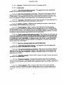
shall present only one legend at a time, i.e., only the legend in use shall be visible. Indicators using
“stacked” legends shall conform to the following:
a.
b.
c.
d.
When the rear legend is energized, i[ shall not be obscured by the front legend.
Parallax shall be minimized.
Front and rear legends shall have approximately equal brightness
Front and mar Jegends shall have approximately equal legendbackground contrast.
5.2.2.3 Simple indicator lights.
5.2.2.3.1 ~. Simple indicator lights should be used when design considerations preclude the
legend lights.
use of
5.2.2.3.2 Spacing. The spacing between adjacent edges of simple round indicator light fixtures
shall be sufficient to permit unambiguous labeling, signal inteprlation, and convenient buIb removal,
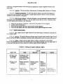
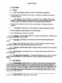
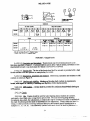
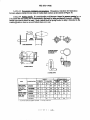
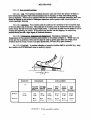
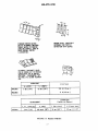
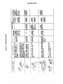
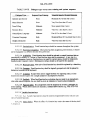
5.2,2.3.3 Coding. Simple indicator Iights shall be coded in conformance with Table II;
however, the different sizes shown are intended onlYfor the attention-~ettituz value that larger lights of
at least equal luminance provide in relation to indim-tor lights of lesser~mpohce.
TABLE IL Coding of simple indicator
SXZETYPE
222mnlmo
(3 to 5 see)
>25 mm (1 in)
STEADY
RED
tights
COLOR
YELLOW
GREEN
WHITE
Emergency condition (impending
personnel or equipment disaster).
Master summation
(system or
subsystem)
Extreme caution
(impending
danger)
Master
summation
(system or
subsystem)
kffilflmrlinn:
action stopped;
laliure, slop U(lwl.
l%li~~ rht=ck:
recheck.
(k-) ahead:
in tolerance:
dGCC~tdbk
rcad~.
1’1
,
MIL-STD-1472E
5.2.2.4 Transilh.uninated panel assemblies.
5.2.2.4.1 ~.
Transilluminamd (integrally lighted) panel assemblies may be used to provide:
a. illuminated labels for a control panel,
b. a light source for illuminating tmnsilluminateci control knobs,
c. illuminated association markings on a control panel (e.g., comczting lines between controls,
outlines around a functionally-related gToupof controls or displays), or
d. a pictorialized representation of a system process, communication network or other
informatioticomponent organization.
5.2.2.4.2 Large, sinale Pictorial mzmhic pane1s. Large, singb pictorial graphic panels, used to
display system processing, communications networks, or similar applications, shall comply with
requirements for visibility, legibility, color, and illumination as specified herein.
5.2.2.4.3 Re-laxrming. When replaceable incandescent lamps are used for integral lighting, they
shall be readily accessible without disconnecting the panel(s). A sufficient numbe~ of lamps shall be
provided so that failure of one lamp will not cause any part of the display to be unreadable.
5.2.2.4.4 Brkhtness. Brightness of illuminated markings and transilluminated controls shidl be
commitible with the ambient environment and operating conditions (e.g., dark adaptation
requkements). Brightness control (dimming) by the o@ator shall be provided where applicable to
maintain appropriate visibility and operator dark adaptation level.
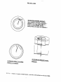
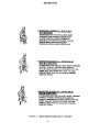
5.2.3 Scak indicators.
5.2.3,1 General
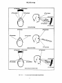
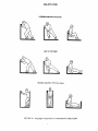
5.2.3.1.1 TvtRs of scale indicators. The types of scale indicators that maybe used include:
a. Moving-pointer, fixed-scale, circular, curved (arc), horizontal straight, and vertical straight.
b. Fixed-pointer, moving-scale, cimuhtr, curved (arc), horizontal straight, and vertical straight.
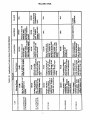
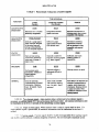
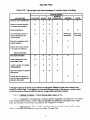
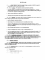
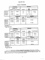
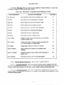
5.2.3.1.2 Use. The me of scale indicators should conform to the criteria in Table Ill and this
section. Moving-inter, fixed-scale indicators are prefencd to fmcd-pointer, moving-scale indkatm
The Mter should be used Gnly when necessitated by operational nxquirements or other conditions, and”
when appmvcd bythepructmng activity.
Scale inchtors should be used to display quantitative
5.2.3.1.3 Type of inf~.
information combined with qualitative information (such as trend and direction-of-motion) and where
on!y quantitative information is to be dispkryed and there is no mquimrmn[ (such as speed and
==lJq@f~)-&dbwd—sa~
5.2.3.1.4 Jmear sca!cs. kixcept where system requirements dictate nonlinearity to satisfy
C)prator lnk)~atlon reqUIR?~n!S, ~l~CW SCdCS 9hd~ k L&d if] pf’t$kJWW h) lM)il/hdi wdkh
5.2.3.1.5
Scale marldng...
523,1.5.
] (j~~dua[ions Scale graduations shall progress by 1, ~, or 5 units or declmd
mllhlpk> ll)clwj
.![)
MUATD-1472E
:1
MIHWD-1472E
5.2.3 .1.5.2 Intermediate marks. The number of minor or intermediate marks between
numbered scale pointers shall not exceed nine.
5.2.3.1.6
Numerals.
5.2.3 .1.6.1 Major marks. Except for measurements that are normally expressed in decimals,
whole numbers shall be used for major graduation marks.
5.2.3 .1.6.2 StartinRpo int. Display scale shall start at zero, except where this would be
inappropriate for the function involved.
5.2.3.1.7
Pointers.
5.2.3 .1.7.1 Length The control or display pointer should extend to, but not overiap, the
shortest scale graduation marks.
5.2.3 .1.7.2 Tip confifzuration. The pointer tip should be tapered at a 20° angle (40° included
angle), terminating in a flat tip equal in width to the minor scale graduations.
5.2.3 .1.7.3 Mounting. The pointer shall be mounted as close as possible to the face of the dial
to minimize parallax.
5.2.3 .1.7.4 Color. Pointer color from the tip to the center of the dial shall be the same as the
of the marks. The tail of the pointer shall be the same color as the diaJ face, unless the tail is used
as an indicator itself or unless the pointer is ustxl for horizontal alignment.
color
5.2.3.1.8 Luminance contrast. A luminance contrast (see MXL-HDBK-1908)not iess than 3.0
shall be provided between the scale face and the markings and pointex.
5.2.3.1.9 Calibration information. Provision shall be made for placing calibration information
on instruments without degmding dial legibtity.
5.2.3.1.10
Cod@
5.2.3 .1.10.1 Use. Coding on the face of scale indicators maybe used to convey such
information as desir~
operating range, inefficient operation, caution, and dangerous level.
5.2.3 .1.10.2 Pattern- or colorading.
Operating conditions that always fail within a given
range on the scale shall be made readily identifiable by applying pattern- or color-coding to that range.
5.2.3 .1.10.3 Choice of colors. Red, yelkow, and green maybe applied, provided they conform
to the meanings specified in 5.2.2.1.18 and are distinguishable under all expected lighting conditions.
5.2.3 .1.10.4 Pattern coding. Zone scales may be shape coded when the indicator must be
viewed in blackout conditions or where the illuminant color will cause difficulty In color band
d~scnmmatmn.
5.2.3.2 Moving-pointer, fixed->cdg .dis@y>
II
.
.
MUAYI’’D-1472E
MIL-STD-1472E
5.2.3 .1.5.2 intermediate marks. The number of minor or intermediate marks between
numbered scale pointers shall not exceed nine.
5.2.3.1.6
whole
Numerals.
5.2.3 .1.6.1 Maior marks. Except for measurements that are notmally expressed in decimals,
numbers shall be used for major graduation marks.
5.2.3 .1.6.2 Startirwpo int. DispIay scale shall start at zero, except where this would be
inappropriate for the function involved.
5.2.3.1.7
Pointers.
5.2.3 .1.7.1 Length The control or display pointer should extend to, but not overlap, the
shortest scale graduation marks.
5.2.3 .1.7.2 Tip conl%ntration. The pointer tip should be tapered at a 20° angle (40° included
angle), terminating in a flat tip equal in width to the minor scale graduations.
5.2.3 .1.7.3 Mounting. The pointer shall be mounted as close as possible to the face of the dial
to minimize parallax.
5.2.3 .1.7.4 Color. Pointer color from the tip to the center of the dial shall be the same as the
color of the marks. The tail of the pointer shall be the same color as the dial face, unless the tail is used
as an indicator itself or unless the pointer is used for horizontal alignment.
5.2.3.1.8 Luminance contrast. A luminance contrast (W MIL-HDBK- 1908) not less than 3.0
shall be provided between the scale face and the markings and pointer.
5.2.3.1.9 Calibration information. Provision shall be made for placing calibration information
on instruments without degrading dial legibfity.
5.2.3.1.10
Coding.
5.2.3 .1.10.1 LJse. Coding on the face of scale indicators maybe used to convey such
information as desir~ operating range, inefficient operation, caution, and dangerous level.
5.2.3 .1.10.2 Pattern-or color-kg.
Operating conditions that always fall within a given
range on the scale shall be made readily identifiable by applying pattern-or color-coding to that range.
5.2.3 .1.10.3 Choice of colors. Red, yellow, and green maybe apphed, provided (hey conform
to the meanings specified in 5.2.2.1.18 and are distinguishable under all expcted lighting conditions.
5.2.3 .1.10.4 Pattern coding. Zone scales may be shape coded when the indicator must be
viewed in blackout conditions or where the illummant co!or will cause difficulty In color band
d]scnmmatmn.
s.2,3. 2 Moving-pointer, fixed-~w.de.@Xw
,,
--
MIL-STD- 1472E
5.2.3.2.2 Orientation. Numbers shall be oriented in the upright position.
5.2.3.2.3 Circular scales.
5.2.3.2.3. 1 ScaIe reading and Winter movement. The magnitude of the scale reading shall
increase with clockwise movement of the pointer.
5.2.3 .2.3.2 Zero POsition and direction of movement. When positive and negative values are
displayed around a zero or a null position, the zero or null point shall be located at either the 12 or
9 o’clock position. The magnitude of positive values shall increase with clockwise movement of the
pointe~ the magnitude of negative values shall increase with counterclockwise movement.
5.2.3 .2.3.3 Scale break. There shall bean obvious break of at least 10° of arc between the two
ends of the scale, except on multirevolution instruments such as clocks.
5.2.3 .2.3.4 Number of minters Whenever precise readings are required not more than two
coaxial pointcm shall be mounted on one indicator face.
5.2.3 .2.3.5 Pointer alimrnent. When a common, stible value exists for given operating
conditions in a group of indicators, the indicators shall be arranged either in rows so that all pointers
Iine up horizontally on the 9 o’clock position under normai opemting conditions or in columns so that
all pointers line up vertically in the 12 o’clock position under normal operating conditions. If a matrix
of indicators is needed, preference shall be given to the 9 o’clock position.
5.2.3 .2.3.6 Relative Dositionof sude marks and numbers. When nxding time and accuracy are
critical, de markings and location of aasociatcd numbers shall be arranged to prevent pointers from
covering any portion of the scale marks or numerals, and scale marks shall be on or close to the plane
of the pointer tip to avoid visual pamliax. If readout accuracy is not critical (i.e., gross relationship
between the pointer and number is all that is required), an arrangement of numerals inside the scale
annuius maybe used. (See Figure 3).
5.2.3.2.4 Curved (arc), horizontal stmkh~ and vertical straight scales.
5.2.3 .2.4.1 Scale readimi and tminter movement. The magnitude of the scale reading shall
increase with movement of the pointer up or to the right.
5.2.3 .2.4.2 Zero rxxition and direction of movements. When positive and negative vaiues are
displayed around a zero point, the magnitude of positive values shall increase with movement of the
with movement of the
@*wmtOtifigM,
~&m@*
d%@vevdw
W~
pointer down or to the left.
5.2.3
.2.4.3
~ofm
the bottom of horizontal scales.
inters. Pointers shall be located to the right of vertical scales and at
5.2.3 .2.4.4 I%acementof numerals. Numerals shall be placed on the side of the graduation
marks away from the pointer to avoid having numbers covered by the inter. ?f space is limited (for
curved or arc scales) numerals may be placed inside of graduation marr s to avoid undue constriction of
the SCilk.
5.2.3 .2.4.5 Pomt~_@rnent.
When a common, stable value exists for given operating
condmons m a group ot mdlcatom, they shd! be arranged aher m rows so chat all pointers Armup
l)ori70nt;dlv (for vertical scales] or in columns s{}thal all pointers line up Vcflically(for h~~i~n[a]
wales )
m
CQ
o
w/&
10
FOR MAXIMW
\
READING
ACCURACY
(THE POINTER IS AN EQUAL DISTMCE NOMINAL 0,6-1.6 mm (0.~l+Wl
im) -
FROM ALL SCALE MARKS, NEVER
OVERLAppfNQ
ANY MARK
OR NIJMERA~}
I
II
TO PREVENT OR MINIMIZE
ALTERNATE
READING
FORMAT
FOR GROS
PARALLAX
OF NUMBERS
a,
.
VISUAL
MIIAYIT)-1472E
5.2.3.3 Fixed-po inter, mcwin~-scale displays.
5.2.3,3,1 Numerical Procession. Numbers shall progress in magnitude in clockwise direction
around the faces of circular dials (counter-clockwise dial movement for numerical increase). On
venkd or horizontal straight scales, numbers shail increase from bottom to top or from left to right.
5.2.3.3.2
Orientation. Numerals shall be upright when in the reading position.
5.2.3.3.3 A.Iknment of pointer or fixed reference line, For circular scales, alignment of pointer
or fixed reference line shall be in the 12 o’clock position for rkht-left directional information and in the
9 o’clock position for up-down information. Fo~ purely quantitative information, either position may
be used.
5.2.3.3.4 Setting. If the display will be used for setting in a value (e.g., tuning in a desired
wavelength), the unused portion of the dial face shall be covered, and the open window shaIl be large
enough to permit at least one numbered graduation to appear at each side of any setting.
5.2.3.3.5 Tracking. If the display will be used for tnwking, as in the case of a directional
indicator, the whole face of the dial shall be exposed.
5.2.3.3,6 Movirm tape displays. When the scale length nxquimd for acceptable readout accuracy
exceeds the limits of the display package capacity (i.e., compressing the scale marking would make the
display illegible or subject to readout error), moving tape scale format maybe used.
5.2.3.3.7 Corrmosite scalar/uictorial disdavs. Combinations of scales, pointers and
pictorialized symbols may be used to combine functionally-related information into a single instrument
or display (e.g., tilcial
horizon, command heading, truehelative bearing). Significant reference
features (e.g., aircraft or ship symbols, horizon, attitude or pitch scales) shall conform to the general
criteria herein for direction-of-motion, scale-pointer relationships, and legibility.
5.2.4 Cathode raYtube (CRT) dis~lavs. CRT displays shall conform to the provisions below;
however, where a CRT is part of a visual display terminal used for text processing, data entry, or data
inquiry applications in an office environment or equivalent, see 5.16.
5.2.4.1 Si~al size, When a target of complex shape is to be distinguished from a nontarget
shape that is also complex, the target signal should subtend not less than 6 mrad (20 minutes) of visual
angle and should subtend not less than 10 lines of resolution elements. Image quality shall be
consistent with the operator’s needs.
5.2.4.2 Viewing distance. A 400 mm ( 16 in) viewing distance shall be provided whenever
practicabk. When periods of scope observation will be b
or when dim signals must be detected,
the viewing distance may be reduced to 250 mm (10 in). Design should petit the o~er
to view
the scope from as close as desired. Displays which must be placed at viewing distances greater than
400 mm ( 16 in) due to other considerations shaIl be appropriately modified in aspects such as dispiay
size, symbol size, brightness ranges, line-pair spacing and resolution.
5.2,4.3 Screen luminance, The ambien[ illuminance shall not contribute more than 25% of
screen brightness through diffuse reflect ion and phosphor excitation. A control shall be provided it)
vtiry the CR-I iummance trom i()% (JImmmwn ambiem hrtinanw 10 i’ullCRT kmnnnce. A LWnU
()i
shall k prnvitim-i
to vat-v the
~wnt rast rat io. (’ontrast
{li~:tll,lll
(’II III
FA .4
turninmm
;d,justment
rrrlll;lfi{m
.
svmlmlkiark
I-wckgrmmd or dtirk svmbol/ll)minous
h~ckgrotlntl
shall not be included m flight deck displays because they are
MIL-STD-1472E
5.2.4.4 Faint signals. When [he detection of faint signals is requiti and when the ambient
illuminance may be above 2,7 lux (0.25 ft-c), scopes shall be hooded, shielded, or recessed. (A
suitable falter system may be employed, subject to approval by the procuring activity.)
5.2.4.5 Luminance rame of adjacent surfaces. The luminance range of surfaces immediately
adjacent to scopes shall be between 10% and 100% of semen baekgmund luminance. With the
exeeption of emergency indicators, no light source in the immediate sumounding area shall be of a
greater iuminance than the CRT signal.
5.2.4.6 Ambient illuminanee. The ambient ilh.tminance in the CRT area shall be appropriate for
other visual functions (e.g., setting controls, reading instruments) but shall not degrade the visibility of
signals on the CRT display. When a CRT display is used in variable ambient illuminance, controls
shall be provided to dim all light sources, including illuminated panels, indicators and switches in the
immediate surround. Automatic adjustment of CRT brightness may be used if the CRT brightness is
automatically adjusted as a function of ambient illurninance and the range of automatic adjustment is
adequate for the full range of ambient illuminance.
5.2.4.7 Reflected dare. Reflected glare shall be minimkd by proper placement of the scope
relative to the light source or by use of a hood or shield, optical coatings on the CRT, or filter control
over the light source.
5.2.4.8 Adiacent surfaces. Surfaces adjacent to the scope shall have a matte finish.
5.2.4.9 Pictoriai/EraPhic situation formats. Pictorial or situation data such as plan position
indicator &@ shall be presented as luminous symbols on a dark background.
5.2.4.10 Font legibility. Where alphanumeric characters appear on CRT-like displays, the font
style shall allow dkMmhrm “on of similar characters, e.g., kmer lhumber 1, letter Zhrnber 2.
5.2.5 Lanze-scxeen displays.
5.2.5.1 ~.
Large-screen displays maybe used under the following conditions:
a. A group of operators frequently refers to the same information and is required to interact as a
team, based on the same information.
b. One or more members of a team of operators must move about, yet must frequently refer to
information required to make decisions—information they cannot crmy with them or do not have
displayed at their assigned position(s).
c. Space
cxotberumlrads
up commonly-used information.
preclude the use of individual displays for each team member to call
d. h may be desirable to have general information available to persons who shou!d not interrupt
on-going group operations by looking over the shoulder(s) of individual operator(s) to see their
individual displays.
5.2.5,2 Avoidance. Large-screen displays shall be used only when the spatial and
LLMJ&&.ML
~OW
sa~sfacto~ observational geometry to ens~lmthat all critical operators
have visual access in terms of viewing distance, angle rind lack of interference from intervening
objects, personnel or ambient hghtmg. It the dqhy is vptkxdy pqieuwd, w 5,2.L.6,
tx~vi~tmllwl)ul
5.5). The display shall not be closer [o any observer than 1/2 the display width or height, whichever is
greater.
5.2.5.4 Physical internmtion of view. Large screen displays shall not be located with respect to
critical observers so that the view of the display is obscured regularly by persons moving in normal
traffic patterns.
5.2.5.5 Control of displayed information, Control of Iarge-scnxn group display systems shall
ensure that critical information cannot be modified or deleted inadvertently or arbitrarily. Changes in
the group display shall be controlled by designated operators who operate according to pre-established
procedures, command of a person in charge, or both. When an individual must make changes that are
of interest only to him or her, a separate, remote display shall be provided.
5.2.5.6 Content of disdaved information. The content of displayed information shall be evident
to a trained observer without requiring reference to display control settings.
5.2.6 Other
displaw.
5.2.6.1 General
5.2.6.1.1 TYpes, When apphcable, direct-reading counters, printers, plotters, flags, optical
projection, LED, gas discharge, liquid crystal and electroluminescent displays may be used.
5.2.6.1.2 Applications. The selection of the above types of displays for various applications
should be based on the following criteria as well as the criteria in Table LH.
5.2.6.2 Counters.
5.2.6.2.1 ~.
Counters should be used to present quantitative data when a continuous trend
indication is not required and when a quick, precise indication is required.
5.2.6.2.2 Mounting. Counters shall be mounted as close as possible to the panel surface to
minimize parallax and shadows and maximize the viewing angle.
5.2.6.2.3 SPacin~ between numerals. The horizonta! separation between numerals shall be
between one-quarter and one-half the numeral width. Commas shall not be used.
5.2.6.2.4
Movement.
a. Snap action. Numbers shall change by snap action in preference to continuous movement.
b. we
expected to -
Numbers shall follow each other not faster than 2 per second when the observer is
then*
consecutively.
c. Direction, The rotation of the counter reset knob shall &clockwise to increase the counter
indication or to reset the counter.
d. Reset. Counters used to indicate the sequencing of equipment shall be designed to be WW[
upn completion d he queltct’.
Pmvisiw) 4MII til~) I* II)* fol Iliwmtd ltx5iillIg
Wherr pllshlw!ttons tire LIse(l to mtin[lHllv rwet mechtinical counten. ac(ualing force rcquirtxl shall Iw
not more than 16.7 N (60 OZ).
titIk HIMtiLdly
MIL-STD-]472E
5,2.6.2.5 Illumination. Counters shall be self-illuminated when used in areas in which ambient
illumination will provide display luminance below 3.5 cd/m2 (1 ft-L).
5.2.6.2.60 Finish. The surface of the counter drums and sumounding areas shall have a matte
finish to minirmze glare.
5.2.6.2.7 Contrast. Color of the numerals and background shall provide high contrast (black on
white or converse, as appropriate).
5.2.6.3 Printm.
5.2.6.3.1 Use. Printers should be used when a visual record of data is necessary or desirable.
Use of printers s=ld conform to Table III.
5.2.6.3.2 Visibiliw. The printed matter shall not be hidden, masked or obscured in a manner
that impairs direct reading.
5.2.6.3.3 Contrast. A luminance contrast (see MIL-I-IDBK-1908) not less than 3.0 shall be
provided between the printed material and the background on which it is printed.
5,2.6.3.4 Illumination. The printer shall be provided with internal illumination if the printed
matter is not legible in the planned operational ambient ilhunination.
5.2.6.3.5 Take-up provision. A take-up device for printed material shall be provided.
5.2.6.3.6 Annotation Where applicable, printem should be mounted so that the printed matter
(e.g., papr, m~
papm) may k easily annotated whiJe still in tbe printer.
5.2.6.3.7 h~bility,
tilt or smear.
The print output shaii be h
from character line mismgistrat.ion,character
mtiem~Nb@ti
wtiitmb
5.2.6.3.8 Printed tapes. Tbtiomtion
is received from the machine without requiring the cutting and pasting of tape sections.
Awit
5.2.6.3.9 Control, reulenishrnent and service. Printers shall conform to the criteria of
5.2.6.4.8,
5.2.6.4 Plotters and recorders.
5,2.6.4.1 Um. Plotters and recorders maybe used when a visual reard of continuous graphic
data is necessary=desirable.
5.2.6.4.2 V-.
Critical graphics (points, curves and grids that must be observed when the
recording is being made) shail not be obscured by pen assembly, arm or other hardware elements.
5.2.6.4.3 ContrasL A luminance contrast (see MIL-HDBK-1908) not less than 1.0 shall be
PJQvti bctw~ the plot~d function and the background on which it is drawn.
5.2.6.4,4 Take-uP device. A take-up device for extruded plotting materials shall he provided
when fwswy
W’dc%habk.
5.2.6.4.5 Job aids. Graphic overtays shouid be prcmkd where themem~ be Aid
h w
shaIl not obscure or distort tie data.
lnmrprrtatmn of graphic datti as It is being generated. SuciI aids
2n
MIL-STD- 1472E
5.2.6.4.6 Smud~indsmearing. The plot should resist smudging or smearing under operational
use.
5.2.6.4.7 Annotation. Where applicable, plotters and recorders should be designed or mounted
so that the operator can write on or mark the paper while it is still in the plotter or recorder.
5.2.6.4.8 Control, replenishment and service. Plotters and recorders shaUconform to criteria
herein with regard to:
a. controls and displays used to starL stop or adjust the machine and critical operating elements;
b. positive
indication of the remaining supply of plotting materiaIs (e.g., paper, ink, ribbon);
c. insertion, adjustment, and removal of paper, replenishment of ink supply, replacement of
pen, or other operator tasks, without requiring disassembly, special equipment or tools; and
d. minor servicing on site by a technician, e.g., adjustment of drive system, ckaning, or
rephtcement of operating items that ordinarily would not be available to an operator.
5.2.6.5 Flags.
5.2.6.5.1 ~.
Flags should be used to display qualitative, non-emergency conditions. Use of
flags should conform to Table III.
5.2.6.5.2 Mounting. Fiags shall be mounted as close to the surface of the panel as possible
without restricting theii movement or obscuring necessary infOrXAatiOn.
5.2.6.5.3 SnaDaction. Flags shall operate by snap action.
5.2.6.5.4 Contrast A luminance contrast (see MIL-HDBK- 1908) not less than 3.0 shall be
provided between flags and their backgrounds under all expected lighting conditions.
5.2.6.5.5 Malfunction indication. When flags are used to indicate the malfunction of a visual
display, the malfunction position of the flag shall obscure part of the rnalfimctioning display and shall
be readily apparent to the operator under all expected levels of illumination.
5.2.6.5.6 Legend When a legend is provided on the flag, the lettering shall appear upright
when the flag assumes the active or no-go position.
5.2.6.5.7 Test movision A convenient means shall be provided to test the operation of flags.
5.2.6.6
~SDl
.
.
.
ays.
5.2.6.6.1 Use. Providing ambient light can be properly controlk4 optical projection displays
are suitable for afications requiring group presentation, pictorial and spatial information, past history
vs real-time presentation, synthetically generated pictures, simulation of the external world, and
superposition of data from more than one source. Rear projection shall be used where physical
obstructions to front projection impair viewing or where work areas require high ambient illumination
[4N , Alwi ddik ilies.
5.2.6.6.2
qwicat
Seatintzarea. Vk!wng cixstancchrnagewrdth rehmonsiup and off-center viewing vi
projection displays for group viewing shouki conform to the preferred limits of Table IV and
not exceed the acceptable hm!ts mdlcated. For indi vidwd viewing [run a freed kaliun, o[f-
shall
.vl?lrr]inc f’icl~’ing~h:lllnot c~crcd Inn
MII#Il)-1472E
TABLE IV. Group
-.—
..
.
viewing ofoptical
projection
displays’
.
FACTOR
““
Ratio of
‘“”-”-”-::laJ=@~:I
viewing distance
screen diagonal
Angle off centerline
20’
Image luminance (no film in operating projector)
27-48 Cd/~*
(8-14 ft-L)
35 Ccihl+
(10 ft-L)
I
~ 17-70 Cd/d*
(5-20 ft-L)
I
I
‘ Lurninanee variation across screen
(ratio of maximum to minimum luminance)
1
3.0
1.5
I
Luminance variation as a function of viewing
location (ratio of maximum to minimum luminance),
I
1’
ambient light
IRatio of
brightest part of image
[
30”
I
o
I
2.0
0.002-0.01
I
4.0
:
0.1 max””
I
“~-Forstill projections higher values may be used
** For presentations not involving gray scale or color (e.g., line drawings, tables) 0.2 may be used.
5.2.6.6.3 hmimuxx and lkht distribution. Image hmimnce and light distribution should
wtiom~ti
_Hmdshti
Mexti&~M&T~k
N. Wmcn
center luminance at maximum viewing angle shall be at least half its maximum luminance.
5.2.6.6.4
Legibility of moiected data.
5.2.6 .6.4.1 &y& A simple style of numerals and letters shall be used. Capital letters (rather
than lower case) shall be used, except for extended copy or lengthy messages. Stroke width shtdl be
1/6 to Ii%of numeral or letter height, but maybe narrower fcx light makings on a dark background.
Stroke width shall be the same for all letters and numerals of equal height. Letter width, numeral
width, character spacing, and word spacing shall conform to 5.5.5.5,5.5.5.6, 5.5.5.10, and
5.5.5. I 1, respectively.
5.2.6 .6.4.2 Size. The height of letters and numerals shaII be not Iess than 3 mrac!( 10 minutes)
and should be not l~than 4.5 mrad (15 minutes) of visual angle, as measured h
the kmgew
tinticipa(eclviewing distance.
5.2.6 .6,4.3
Contrast.
5.2.6 .6.4.3.1 .,Luminanceratio. Under optimal ambient lighting conditions, the luminance ratin
\.W AM
IL-I lDBK
- i 908 ) should Ix 500.1. ‘Ilc luImI~ancc riuw for Jicu’ing chiuls, prin[cd LCX(
WIL1
other line umk ~’ia slidcf or opaqtle prelectors Khan he not less than 5:1. For pmyxtions wh~ch tire
i( I
MILSTD-1472E
limited in shadows and detail, such as animation and photographs with limited luminance range, the
luminance ratio shall be not less than 25:1. For images which show a full range of colors (or grays in
black-and-white photographs), the luminance ratio shall be not kss than 100:1.
5.2.6 .6.4.3.2 Direction of contrast. Contrast maybe either light on a dark background or vicevers~ except where superposition is used. For subtractive superposition (at the source), data shall be
presented as dark markings on a transparent background. For additive superposition (at the screen),
data shaIl be presented as light markings on an opaque background. Colored markings against colored
backgrounds of comparable brightness shall be avoided.
5.2.6 .6.4.4 Alignment. Misregistration of superimposed alphanumeric data or other symbols
shall be minimized.
5.2.6.6.5 Keystone effects. Projector-screen arrangement shall minimize keystone effects
(distortion of projected data proportions due to non-perpendicularity between projector and screen).
5.2.6.7
5.2.6.7.1
Light emitting diodes (LEDs].
General. Unless specified below, LEDs shall conform to 5.2.2.
5.2.6.7.2 ~.
I-Ells maybe used for transilluminated displays, including legend and simple
indicator lights, and for matrix (alphanumeric) displays, only if the display is bright enough to be
readable in the environment of intended use (enclosure, bright suniight, low temperature).
5.2.6.7.3 Intensitv control. The dimming of LEDs should be compatible with the dimming of
incandescent lamps.
5.2.6.7.4 Color coding With the exception of- alpha-numeric displays, LED color coding
shall conform to 5.2.2.1.18; however, red LEDs should not be located near red fights used as outlined
in 5.2.2.1.18.
5.2.6.7.5 km) testing LED indicator lights with 100,000 hours or longer mean time between
failure (MTBF) shall not require the lamp test capabfity specifkd in 5.2.2.1.14.
5.2.6.8 Dot matrhdsegme nted disnlavs.
5.2.6.8.1
General. The following provisions apply to those displays (LED, CRT, gas
discharge, liquid crystal, and incandescent) used to pment alphanumeric and symbolic information.
5.2.6.8.2 Use. Dot matrix, fourteen segment, and sixteen segment displays may be used for
intenMive mnputer !iyslums, ktmmmts, avionics, navigation, and
apphcatkms m-g
communication equiprneng where the pmstmtation of alphan~ric,
vector-graphic, symbolic or realtime information is quid.
Seven segment displays shall he used only for applications requiring
numeric information.
5.2,6.8.3
Symbol &fti&ion. Dot matrix characters shall contain not less than 5 by 7 dots, with
7 by 9 preferred. If system requirements call for symbol rotation, dot matrix characters shall contain
not less than 8 by 11 dots, with 15 by 21 prefemed.
5,2.6,8.4
.4!tyhmumerir character and svmhol sires. Aiphwmmeric characters and svmtxds
shrill suhtencl not less than 4,7 mrad (16 rein) of visual angle. Aircraft display characters and symbols
II,, !I 111I,!. t h(l !.l.;i,I ill fli:llt
<h; Ill <Ilht(vl(l not Its< th; m7 n-mad (24 rein) of visual anrlc
,{ I
MUATD-1472E
5.2.6.8,6 Viewing angle. The optimum viewing angle is perpendicular to the display. Viewing
angle of matrix or segmented displays should be not more than 35° off axis.
5.2.6.8.7 Emitter edor. Monochromatic displays shall use the following colors in order of
preference: green (555 rim), yellow (575 rim), orange (585 rim), md red (660 rim). Blue emitters
should be avoided. The sekcted color should be visible through laser protective (or other) eyewear
required to be worn by the user.
5.2.6.8.8 lntensi~ control. Where applicable, dimming controls shall be provided to maintain
appropriate legibility and operator dark adaptation level.
5.2.6.8.9
Display testing. See 5.2.6.7.5.
5.2.6.8.10 Location of red alphanumeric LEDs/se~mented displays. Red LEDs/segmented
displays shall not be grouped with or heated adjacent to red warning lights.
5.2.6.9 Eiectrolumineseent displays.
5.2.6.9.1 &. Electroluminescent (EL) displays may be used where system requirements
dictate the use of transilhninated displays. In addition, they maybe used instead of mechanical
instmments: They are lighter, use less panel space, require less power, produce no heat, distribute
uniform illumination, offer longer life, eliminate parallax, and provide display flexibility. EL displays
may also be used where sudden lamp failure could result in catastrophic consequences.
5.2.6.9.2 AManumeric character and sYrnbolsizes. The height of alphanumeric characters and
geometric and pictorial symbols shall subtend not less than 4.5 rnrad ( 15 minutes) of visuaJ angle.
A@hanumerical characters shall be upper case. Aircraft display characters and symbols that must be
read in flight shall subtend not less than 7 mrad (24 tin) of visual angle.
MIL-STD-1472E
5,3 Audio dimkws.
5.3.1 General.
5.3,1.1 ~.
Audio displays should be provided under the following conditions:
a. The information to be processed is short, simple, and transitory, requiring an immediate or
time-based response.
b,
The common mode of visual display is restricted by over-burdening; ambient light
variability or limitation; operator mobility; degradation of vision by vibration, high g-forces,
hypoxi~ or other environmental considerations; or anticipated operator inattention.
c. The criticality of transmission response makes supplementary or redundant notification
desirable.
d.
It is desimble to wnrn, aim or cue the opemtor to subsequent additional response.
e. Custom or usage has mated anticipation of an audio display,
f. Voice communication is necessary or desirable.
5.3.1.2 Si@ tMM. When an audio presentation is rquired, the optimum type of signal should
be presented in aecordatw with the Table V.
5.3.1.3 False alarms. The design of audio display deviees and circuits shall preclude false
alarms.
5.3.1.4 Faikm The audio display deviee and circuit shall be designed
signal failure in the event of system or quipment failure and vice versa.
to
preclude warning
5.3.1.5 Cimuit test, All audio dispAaysshall be equipped with circuit tcstdeviees or other means
of operability test.
5.3.1.6 Aircrew stations. Audio signals for air crew stations shall conform toMIIATD-411,
where applicable.
5.3.1.7 Use with several visual disdavs. If immedate dkximbu “onis not critical to personnel
safety or system perfomanec, one audio signal may be used in conjunction with severs! visual
displays.
5.3.2 Audio warnkm
5.3.2.1 Warnimz simils.
Signals should be provided to warn pcxsonnel of impending danger,
in system or equipment status, and to remind an operator of a
critical action or ackns that mW be taken. An Amingkamkg
eignal shall provide the OpOratmwith
~ seater p~babiliu of detecting thc ~mring Condition than normal observation would provide in the
absence of the signal. NOTE: Certain audio signals have been standardized for aircraft use by joint
scrvicc and irx.ernational agmzmcnt. Aadiu sqpds for futureaircrah design shoutd corrhrm to them
figrccmcnts (see MIL-STD-41 1),
to alert an operator to a titicai
change
MIL-STD- 1472E
TABLEV. Functional
evaluation
of audio signals
.
.
!4
Q
FU?WITON
TONES
(F&kdic)
TYPEOF SIGNAL
SPEECH
COMPLEX SOUNDS
(Non-Periodic)
—
QU/WIl’TATfVE
INDICATION
QUALITATIVE
INDICATION
POOR
POOR
Maximum of 5 to 6 tones
absolutely recognizable
interpolation between
signals inaccurate.
imate valueand direction
Difficult to judge
approximate &vition
of deviation fromnull
fromdesiredvalue.
setting unless presentd
in close temporal sequence.
STATUS
INDICATION
GOOD
Start and stop timing.
Continuous information
1 where rate of chmge of
input is low.
GOOD
Information concerting
L diractiom
dkpkaen
~-pdbfm
-w
with required
response.
POOR
GOOD
Especially suitable for
irregularly occurring signals
(e.g., alarm signals).
Ineffkient; more easily
~:ji.jbkm
of
POOR
~
TRACKING
Minimum time anderror in
obtaining exact value in terms
=JP@ti* Withrespome.
POOR
POOR-TO-FAIR
Difficult to judge approx-
GOOD
Null position easily
monitored; problem of
signak3aponSe
Requixxxtqualitative
GQQQ
Meaning intrinsic in signal.
indications difficult to
provide.
, compatibility
GENERAL
Good for automatic
communication of limited
information. Meaning
must be learned. Easily
Some sounds available
with common meaning
(e.g., fire bell). Easily
Most effeetive for rapid (but not
automatic) eorttmtmieation of
compkx, multidimensional
genelatd.
information. Meaning intrinsic
in signal and eontcxt when
generated.
stankiid.
Minimum of new
--
5.3.2.2.1 Two element simtals. when reaction time is critical and a two element signal is
necessary, an alerting signal of 0.5 second duration shall be provided. All essential information shall
&~n._ti*fim2.O~&**i~m*ti&.
SingJe,elcment
sigryd.
When reaction time is critical, signals shall be short, lf a
——
..
element signal is permissible, all essenrxat information shali be transmitted m the tirst 0.5
JCCm!.
5.3.2.2.2
single
s I ? ? ~;lll[ioll
~ion;]ls
and shall he Iiscd to indicate
C’alj(ion signals shall hc readily distinguishable
from warning yignal~
conditions requiring awmmess, but not necessarily immediate itchon.
34
MM’I’’D-1472E
5,3.2.4 Relation to visual dis~lays, When used in conjunction with visual displays, audio
warning devices shall be supplementary or supportive. The audio signal shall be used to alert and
direct operator attention to the appropriate visual display,
5.3.3 Characteristics of audio wamin~ simmls.
5.3.3.1 Freuuency.
I
5.3.3.1.1 Rarme. The frequency range shall be between 200 and 5,000 Hz and, if possible,
between 500 and 3,000 Hz. When signals must travel over 300 m (985 ft), sounds with fnquencies
below 1,000 Hz should be used. Frequencies below 500 Hz should be used when signals must bend
around obstacles or pass through partitions. The selected frequency band shall differ from the most
intense background frequencies and shall be in accordance with other criteria in this section.
5.3.3.1.2 Electric power fnxmency avoidance. The frequency of a warning tone shall be
different from that of the electric power employed in the system.
5.3.3.2 Intensity.
5.3.3.2.1 CornpatibiliW with acoustical environment. The intensity, duration and source
location of audio alarms and signals sh~ be compatible with the acoustical environment of the
intended receiver as well as the requirements of other personnel in the signal axeas.
5.3.3.2.2 Comatibilitv with clothim and euuimnent. Audio signals shall be loud enough to be
heard and understood through equipment or gaments (e.g., parka hood, NBC protective hood,
hearing protective devices) covering the ears of the listener.
5.3.3.2.3 Discomfort. Audio warning sigmds should not be of such intensity as to cause
discomfort or “ringing” in the ears.
5.3.4 Signal c~
“ “Csirtrelation tocnlemtl“Onalu)nditions and Objectives.
5.3.4.1 Audibil&y. A signal-@noise ratio of at least 20 dB shall be provided in at least one
octave band between 200 and 5,000 Hz at the operating position of the intended receiver.
5.3.4.2 Alertirm camdility.
5.3.4.2.1 Attention- Signals with high alerting capacity should be provided when the system or
equipment requires the opemtor to eommmte amniort. Such signals shall ~ imwever, be so
startling as to preclude appropriate responses or interfere with other functions by holding attention
mveyfrwnetherorA.iod@ruda.
level. The onset of critical alerting signals should be
5.3,4.2.2 Onset and SOLUAd mssure
sudden, and a relatively high sound pressure level should be provided as specified 5.3.4.1.
5.3.4.2.3 Dichotic uresataho“ n. When earphones will be worn in the operational situation, a
dichotic presentation should be used whenever feasib~e, alternating the signal from one ear to the other
hy means of a dual-channel headse(.
5 24.
z 4
He~dset,
When
the operator
is Wetiring
earphones
c~verin~
Wh
ears during
normal
opera-e
audio warning signal shall be directed to the operator’s headset as well as to
II)(’!! ’01”!( ;11{’;1 Rinatlrol hedwts should not he used in any opcrntinnal environment helm R5 dRA
WhCIC souIIds t.hut prm’ide llw operator with useful information cannot bc dircc(ed to the operator’s
equipment
MII#ID-1472E
headset. Such sounds may include voices, machine noise that indicates wear or malfunction and other
audible indications of system performancdmission status.
5.3.4.3 Discriminability.
5.3.4.3.1 Use of different characteristics. When several different audio signals are to be used to
alert an operator to different types of conditions, discriminable difference in intensity or pitch, or use
of beats and harmonics shall bc provided. If absolute discrimination is required, the number of signals
to bc identified shall not exceed four.
5.3.4.3.2 Coding. Where discrimination of warning signais tim each other wiU be critical to
persomel safety or system performance, audio signals shall be appropriately coded. Alarms thatare
perceptibly different shall correlate with different conditions requiring critically different operator
responses (e.g., maintenance, emergency conditions, and health hazards). Such signals shall be
suff~iently different to rninimk the operator’s search of visual dispIays.
5.3.4.3.3 Critical simtals. The fimt 0.5 second of an audio signal requiring fasi reaction shall be
disaiminable from the fkt 0.5 second of any other signal that may occur. Famiiiar signals with
established names or associations shall be selected. Speech should be used whenever feasible.
5.3.4.3.4 Action serenent. The identifying or action segment of an audio warning signai shall
speci& the precise emergcney or condition requiring action.
5.3.4.3.5 Differentiation from routine signals. Audio alarms intended to bring the operator’s
attention to a malfunction or failure shall be diffemntked fhrn routine signals, such as bdb, buzzers,
and normal operation noises.
5.3.4.3.6 Prohibited types of sifznak. The following types of signals shall not be used as
warnings where possible confusion might exist bemuse of the operational environment
a. Moduktd
b.
or interrupted tones that resembk navigation signals or coded radio transmissions.
Steady
signals that mcmbk
hisses, static, or sporadic radio signals.
c. Trains of impulses that resemble electrical interference, whether regularly or imegularly spaced
in time.
d.
Simple warbles which may be confusod with the type made by two carriers when one is
being shifted in frequency (beat-frequency-oscillator efYcct).
e. Scrambled speech cfftcts that maybe confined with cress mdukion
Signale from @aloeal
channels.
f. Signals that resemble random noise, periodic pulses, steady or frequency modulated simple
tones, or any other signals generated by standard countermeasure devices (e.g., “bagpipes”).
l?.
Signals similar to random noise generated by air conditioning
5.3.4.4
Compatibility.
or any other equipment
5.3.4.4.1 Existing simtals. The meaning of audio warning signals selected for a system should
k L(IIISISUJmivith t~arning sign;ll mc;min:~ iilr(>ii(i~ rstablisht~d for that fl[nctinn
MIL-STD-1472E
5.3,4,4.2 Acoustic environrnen(. Established signals shal! be used, provided they are
conmatible with the acoustic environment and the requirements specified herein for the voice
communication system. Standard signals shall not k used to convey new meanings.
5.3.4.5 Masking
5.3.4.5.1 Other critical channels. Audio warning signals shall not interfere with any other
critical fimctions or warning signals, or mask any other critical audio signals.
5.3.4.5.2 Setmrate channels. Where a warning signal delivered to a headset might mask another
essential audio signal, separate channels may be provided to direct the warning signal to one ear and
the other essential audio signal to the other ear, When required by operating conditions, this dichotic
presentation may also alternate the two signals from ear to ear.
5.3.5 Verbal warniw signals.
5.3.5.1 Nature of signals Verbal warning signals shall consist of
a, an initial alerting (non speech) signal to attract attention and to designate the general problem,
and
b.
a brief standardized verbal message to identi~ the specific condition and to suggest
appropriate action.
5.3.5.2 Intensity. Verbal alarms for critical functions shall be not less than 20 dB above the
speech interference level at the operating position of the intended receiver.
5.3.5.3 vocal
cderia5.3.5.3.1 Type of voice. The voice shall be distinctive and mature.
5.3.5.3.2
Delivcrv stvle. The messages shall be presented in a formal, impersonal manner.
h Processing. Verbal warning signals shall be processed only when necessary to
5.3.5.4 sPeec
incnmse or presewe intelligibility, such as by increasing the strength of consonant sounds relative to
vowel strength. Where a signal must be relatively intense because of high ambient noise, peakclipping (see MIL-HDBK- 1908) may be used to protect the listener against auditory overload.
5.3.5.5 Message content. Word selection priority shall be intelligibility, aptness, and
conciseness, in that order.
5.3.5.6 Critical warnings
5.3.5.6.1
and Priorities.
Critical wamin~ simm.ls. Critical warning signals shall be repeated with not more than
a 3-seccmd pause between messages until the condition
is corrected or overridden
by the crew.
s,s. s .6.2 Message Priorities. A priority system shall k established to ensure tha[ higher
criticality messages ovcrzide the presentation of lesser priority messages. If two or more incidents m
malfunctions occur slmukmeousl y, the message ha~’mg the h!ghcr pmonty shall he gl ven tIrst. i he
r~m~jnjng messngef shnl! fn!lnw in nrder nf prinri~
In the event of a completr sllhsysrem t%illm= the
wstcm
, ,IIlj\
shall integrate previous rne.ssages via electronic gating and repori the sulwvstem rather than the
1111,,111
I.,lillllt.’
—
MII/STD-1472E
5.3.6 Controls for audio warning devices.
5.3.6.1 Automatic or manual shut-off. When an audio signal is designed to persist as long as it
useful information, a shut-off switch, controllable by the operator, the sensing mechanism,
or both, shall be provided, depending on the operational situation and safety factors.
contributes
5.3.6.2 Automatic rtwt. Whether an audio warning signal is designed to be terminated
manually, or both, an automatic reset function shall be provided. The automatic reset
function shall be controlled by the sensing mdianism which shall recycle the signal system to a
specified condition as a function of time or the state of the signaling system so that the warning device
can sound again if the condition repeats.
automatically,
5.3.6.3 Redundant Visual Warning. AUnon-verbal aural annunciations shall be accompanied
visual annunciation which defines the condition. In a cockpit, this maybe an illuminated display.
In the case of a warning horn on a backing vehicle, the vehicle’s backward motion is adequate
redundancy.
by a
5.3.6.4 Vohum?contd
5.3.6.4.1 Automatic or manual. The volume (loudness) of an audio warning signal shall be
designed to be controlled by the operator, the sensing mechanism, or both, depending on the
operational situation and personnel safety factors. Control movements shall be restricted to prevent
reducing the volume to an inaudible level.
5.3.6.4.2 Gan@rMto mode switches. Volume cmtrols may be ganged to mode switches to
provide hma~d~tiim
p-wtib~-ti=
wy~tim~~~
volume at other times. Ganging shall not be used if intense noise may occur during an emergency in a
mission phase when the volume would be decreased below an audible level.
5.3.6.4.3 Caution sid
and volume controls.
controls. Audio caution signals shall be provided with manual reset
5.3.6.5 Duration. Audio warning signal duration shall beat kast 0.5 second, and may continue
until the approprhte response is made. Completion of a wrmctive tction by the operator or by other
means shall litttomtltidy W’min@ the signal.
5.3.6.6 Duration lhitations. Signals that persist or incxease progressively in level shall not be
used for emergency situations if manual shut-off may interfere with the corrective action rapired.
5.3.7 Speec
h transmission euuiment.
5.3.7.1 Fmctuency. Microphones and associated system-input devices shall respond optimdiy
of the spech spectrum most essential to intelligibility (i.e., 200 to 6,100 Hz). Where
system engineering necessitates speech-tmnsrnission bandwidths nanuwerthan 200t06,100Hz, the
minimum acceptabk hquertcy range shall be 250 to 4,000 Hz.
to that part
5.3,7.2 Dynamic range. The dynamic range of a microphone used with a selected ampiifier
wide enough to admit variations in signal input of at least 50 dB.
shall be
canceling
mjc rophmm
In very loud, low frequency noise environments ( i00
.5 ‘4
. 7 ~ ~ojsc
(IB overall), noise canceling microphones shall he u,sed and shall be capable of achieving an
iIIIIII (}J t’11)(>111l~fnot k’s~[hiin 10 d13 pc:Ik ~perch In root mean -square-noiw rntio as cnmp:]rd
Ikrith
I)(NI- noi.w-wncelinp
nticrophunes of equivalcn[ transmission characteristics.
MIL-STD- 1472E
5,3.7.4 Pre-emPhasis. If necessary, speech system input devices should employ frequency preemphasis with a positive slope frequency characteristic no greater than 18 dB per octave from 140 to
1,500 to and no greater than 9 dB per octave over the frequency range 1,500 to 4,800 Hz, when no
clipping is used.
5.3.7.5 Peak+lir.minR ofs txzch simxals. Where speeeh signals arc to be transmitted over
channels showing less than 15 dB peak-speech to root-mean-square-noise ratios, peak clipping of 12
to 20 dB maybe employed at system input and may be preceded by frequency pre-emphasis as
specified in 5.3.7.4.
5.3.7.6 Noise shields. When the talker is in an intense noise field, the microphone should be
put in a noise shield. Noise shields should be meet the following requirements:
a. A volume of at least 250 cu cm ( 15.25 cu in) shall be provided to permit a pressure gradient
microphone to function normally.
b.
A good seal shall be provided against the face with the pressure of the hand or the
tension of straps.
c. A hole or combination of holes covering a total area of 65 sq mm (O.1 sq in) shall be provided
in the shield to prevent pressure buildup.
d.
Standing wave patterns shall be prevented by shape, or by use of sound absorbing
material.
e. The shield shall present no impediment to voice effort, mouth, jaw movement or breathing.
5.3.8 SLXX@I’CZ42DtiOn
m ubment.
5.3.8.1 FHuencY rarwe. Headphones and loudspeakers shall be subject to the same frequency
response restrictions 8s microphom 8nd transmission qui~t
except that hudspakers fbr use in
multi-speaker installations and multiple channels fed into headphones (e.g., where several speech
channels are to be monitonxi simultaneously) shall respond uniformly (A dB) from 100 to 4,800 Hz.
5.3.8.2 Loudspeakers for multi-channel monitoring.
5.3.8.2.1 Monitoring of speakers. If several channels are to be monitored simultaneously by
means of loudspeakers, the speakem shall be mounted at least 10“ apart in the horizontal plane frontal
quadrant fiwm 45° ieft to 45° tight of the operator’s normal forward ikcing position.
5.3,43,2.2 FWhenad&tic@ chatmel differentiation is requhui, apparent lateral
separation shall be enhaneai by applying low-pass filtenn~ (fre uency cutoff = 1,800 Hz) to signids
fed to loudspeakers on one side of the central operator position. % three cbannek are invoIv4 one
channel shaIl be left unfiltered, a high pass filter with 1,000 Hz cutoff sIMIIbe provided in the second
channel, and a low-pass filter with 2$00 Hz cutoff shaJl be provided in the third channel. A visual
tigud shall be pmvidcd to show which channel is in use.
5.3.8.3 U= ofde-emphasm When transmission equipment employs pre-emphasis and peak
Ciqq}ing i+ mx MA, wupkxl cq.uipmcnt dull employ frequency de-emphasis of characterist ics
complementary to tho,seof pre-emphasis only if it improves intelligibility, i.e., de-emphasis shall be a
negative-slop fkqueney response not grwter than 9 CMper oetuve cwer the %eqt.uwy fwi~ MO k
4,MI0 H7
MIL-STD- 1472E
5.3.8.4 Headsets. lflisteners wil!woti inhighambtent noiw(85dBA orabve), binaural
rather than monaural headsets shall be provided. Unless operational tequitments dictate otherwise,
binaural headsets shall be wired so that the sound reaches the two ears in opposing phases. Their
attenuation qualities should be capable of reducing the ambient noise level to less than 85 dBA.
Provisions should be incorporated to furnish the same protection to those who wear glasses.
5.3.9 Operator comfort and convenience.
5.3.9.1 Comfort Communication equipment to be worn by an operator (e.g., headphones and
telephone headsets) shall be designed to preclude operator discomfort. Metal parts of the headset shall
not come in contact with the user’s skin.
5.3.9.2 Hands-free omxation. Operator microphones, headphones, and telephone headsets
shall be designed to permit hands-frw operation under normal working conditions.
5.3.9.3 Accessibility of handsets. Where communication requirements necessitate the use of
several telephone handsets, the accessibility of theii standby locations shall be determined by
operational priority, i.e., the most frquent.ly or urgentiy needed handset shall be the most ~ible.
The handsets may also be color coded if they will be visible to operating pmonnel under the working
conditions.
5.3.10
Ope
rating controls for voice communication equimnent.
5.3.10.1 Volume controls. Accessible volume or gain controls shall be provided for each
communication receiving channel (e.g., loudspeakers or headphones) with sufficient electrical power
to drive sound pressure level to at least 100 dB overall when using two earphones, and shall have
pressure operated gain control switches to compensate for altitude in unpressurized compartments.
The minimum setting of the volume control shall be limited to an audible leve~ i.e,, it shall no{be
possible to inadvertently disable the system with the volume control. Power (on-off) and volume
adjustment should not be combined into the same contxd; however, if conditions jqstify their
cornbiiation, a notiaxtble detent position shall be provided between the OFF position and the lower
end of the continuous range of volume adjustment. When combined power and volume controls are
used, the OFF position shall be labeled.
5.3.10.2 SqueJch control. Where communication channels are to be continuously monitoti
each channei shall be provided with a signal-activated switching device (squelch control) to suppress
channel noise during no-signal periods. A manually operated on-off switch, to deactivate the squelch
when receiving weak signals, shall be provided.
5.3.10.3
Foot-oWrated controls. When normal vvmking conditions tiil pemtit the opmtor to
remain seated at the working position and require access to “talk-iisten” or “send-receive” control
switches, orifeonsOk 0pmtionrc@rc9
ehctlsevfb@h hands, kmt-Qpemtd wntr0lsshaUk
prwided. ~titikti~~t
ib~ovtifu~~y~tifor
use when the operator may need to move from one position to another.
5.3.11 Sueaker/side tone. The speaker’s verbal input shall be in phase with its reproduction as
heard on the headset. This @e tone 4wU not be filwed or mdificd before it is rcccived in the
headset.
5.3.12
S~ech
..— mtelluzlbdlty.
53 12,1 General.
When information concerning the speech intelligibility
of a system is
..-— . .
1,’,.l~.lir~*,\{
threr wrommcndcfi
methods are ~vailah]e. w]th the appro~riate selection hcin~ dependent
upon the rcquircmcnls nf the test
4(’-)
.— ...—.
.... . .
.,_____.
MIL-STD-1472E
a. The standard method of measuring phonetically balanced (PB) monosyllabic word
intelligibility, ANSI S3.2, should be used when high test sensitivity and accumcy are
required.
b.
The modified rhyme test (MRT) (see Human Engineering Guide to Equipment Design)
should be used if the test requirements are not as stringent or if time and training do not permit
the use of the ANSI method.
c. Articulation index (AI) calculations should be used for estimations, comparison and
predictions of system intelligibility based upon ANSI S3.5.
5.3.12.2 Criteria The intelligibility criteria shown in Table VI shall be used for voice
communication. The efficiency of communications needed and the type material to be transmitted shall
determine which of the three communication requirements of Table VI is to be selected.
TABLE VI. Intelligibility
criteria for voice communication
systems
SCORE
COMMUNICATION REQUIREMENT
PB IMRTI
I Exceptionally high intelligibility; separate syllables understood
Normal acceptable intelligibility;
heard; single digits understood
about 98%
I 90% I 9770 I 0.7
of sentences comctly
1
Minimally acceptable intelligibility; limited standardize phrases
understood; about 90% sentences cornxtl y heard (not acceptable for
operational quipment)
AI
I
75%
43%
II
I
91%
75%
I
0.5
0.3
MIL-STD- 1472E
5.4
Controls.
5.4.1 General criteria.
5.4.1,1 Selection.
5.4,1 .1.1 Distribution of work load. Controls shall be selected and distributed so thatnone of
the operator’s limbs will be overburdened.
5.4.1 .1.2 G-loading. Where applicable, control selection shall consider operation under
variable g-loading on the operator.
5.4.1 .1.3 Multimtation controls. Mtdtirotation controls shall be usc.dwhen precision is required
over a wide range of adjustment.
5.4.1 .1.4 Detent controls. Detent contmk shall be selected whenever the operational mode
requires control operation in discrete steps.
5.4,1.1.5 Stops. Stops shall be provided at the beginning and end of the range of control
positions if the control is not to be operated beyond the indicated end positions or specified limits.
5.4.1.2 Dimxxionof movement.
5.4.1.2.1 Consistency of movement. Direztion of control movement shall be consistent with the
related movement of an associated display, equipment componen~ or vehicle. in generai, movement
of a control forward, clockwise to the nghL or up, or pressing a controi, shall turn the equipment or
component on, cause the quantity to increase, or cause the equipment or component to move fonvard,
clockwise, to the right, or up. Valve controls are excepted (see 5.4.1.2.4).
5.4.1 .2.2 Multidimensional oueration. When the vehicle, equipment, or components may
move in more than two dimensions, exception to 5.4.1.2,1 shail be made if necessary to ensure
consistency of anticipated response (e.g., forward motion of a directional control causes sortw vehicles
to dive or otherwise descend rather than to simply move forward). When several cuntrcds are
combined in one device, responses shall be compatible with cent.ml movement (e.g., control motion to
the right is compatible with clockwise roll, right turn,and dinzt movement to the right).
5.4.1 .2.3 Operator-amtrol orientation. Controls shall be oriented with respect to the operator.
wem a vehicle operator may use two or more stations, the controls shall cause movement oriented to
the operator at the effecting station, unless remote visual reference is med.
5.4.1 .2.4 Valve controls. Rotary waive controls should open the valve with a counterclockwise
motion. Valve controls shall be ptwkkd with (httbte-ended armwsshmving thedinxtionof
operations and labeled at each end to indicate the functional math (e.g., open and cdom).
5,4.1.3 Arrangement and grouping.
5.4. !.3.1 OKuq?in~. comdswhiuh em Opera@din&ti&wqwu@Jwu=
operated together shall be grouped together along with their associated displays. When several steps
of a sequence are selected by one control, the steps shall be arranged by order of occwrence to
minimize control movements and prevent cychng through unnecessary steps. Cychng through the
timml’s ON/OIT ,pasii.ions!MI1bc avcic!ec!
MII/STD-1472E
5.4.1 ,3.3 Location of PrimMYcontrols. The most important and frequently used controls
(PticuladY rotary controls and those requiring fme settings) shall have the most favorable position for
ease of reaching and grasping.
5.4.1.3.4 Consistency. The arrangement of functionally similar, or identical, prirnaty controls
shall be consistent fkom panel to panel throughout the system, equipment, or vehicle, e.g., a
movement of a control to the right or left should resuh in a corresponding movement of a displayed
element to the right or left.
5.4.1 .3.5 Remote controls. Controls, operated at a position remote fmm the display,
equipment, or controlled vehicle, shall be arranged to facilitate direction-of-movement consistency,
5.4.1.3.6 Maintenance and adjustment. In general, controls used sole!y for maintenance and
adjustment shall be covered during normal equipment operation, but shall be readily accessible and
visible to the maintenance tdmiciatt when required.
5.4.1.3.7 Spacing. Minimum sp~ing between controls shall comply with Table WI. Spacing
between a control and any adjacent obstruction shall be as shown by the figures referenced by Tabie
WI. Minimum spacing shown shall be increased for operation with gloves, mittens, or NBC
protective handwear, when such operation is a system requirement.
5.4.1.4 Coding.
5.4.1 .4.1 Methods and requirements. The use of a coding mode (e.g., size and color) for a
particular application shall be governed by the relative advantages and disadvantages of each type of
coding (see Tabk VIII). Where coding is used to differentiate among controls, application of the code
shall be uniform throughout the system.
5.4.1 .4.2 Locationadi.ng. Controls associated with sirnikr functions should be in the same
relative location from work station to work station and fmm panel to panel.
5.4.1.4.3 size’u3din& No more than three different sizx shall be used to code controls for
discrhinati on by absolute sire. Controls used for ptxfcmning the same function on different iterns of
equipment shall be the same size. WherI knob diameter is used as the coding parameter, differences
between diameters shall be not less than 13 mm (0.5 in). When knob thickness is the coding
parameter, differences between thicknesses shall be not less than 10 mm td.4 in).
5.4.1 .4.4 shape -cod@ Shape coding, when used, shall ensure identification of control knobs
or handles by “fee!.” When shape coding is used
b.
Shapes shall be identifiable by hand and by eye regardless of the position and
orientation of the control knob or handle.
c.
Shapes shall be @c@allyiden@able when gloves must be worn.
d.
The number of shapes to be identified by each operator based on absolute
Chcmmmmort Sitzdi”tlenut rnorc”than ten.
e. Shape coded knobs and handles shall be positively and non-reversibly attached m their shafts
1(\I)r(*(.ll]drincw-rt=ct
:Ift
xhmenf \\’hen replacement i<required
MIL-STD- 1472E
TABLE VII. Minimum, edge-to-edge
separation distances
for controls
.
ROTARY
DISCRETE
SELHXOR THI.JMBWHEEL
CONTROLS Swrram
CONTROLS
CONTINUOUS
TOOGLE
Swrrcm
PusmmNsl
SEE FIG 13
13 mm (0.5 in)
13 mm
(0.5in)
19 mm (0.75 in)
(0,75in)
13 mm (0.5 in)
(0.5in)
13mm (0.5in)
13 mm (0.5in)
SEE FIG 7
25 mm (1.0 in)
19 mm(0.75 in)
13 mm
SEE FIG 11
19 mm
Comous
ROTARY
CONTROLS
ROTARY
SELECN)R
DISCRETE
THUMBWHEEL
CONTROLS
(0.5in)
19mm(0.75m)
13 mm
19mm (0.75
13 mm (0.5 in)
13
mm (0.5
m)
in)
I 3 mm (0.5
25 mm
in)
(1.0 in)
19 mm (0.75 in)
SEEFIG4
19 mm (0.75 in)
I 9 mm (0.75in)
SEE FIG 6
1
NOTE: All values are for one hand operation.
Lfor pushbuttons not separated by barriers
5.4.1 .4.5 Color-coding
5.4.1 .4.5.1 Choice of colors. Controls shall be black (17038, 27038, or 37038) or gray
(2623 1 or 3623 1). If color coding is required, only the following colors identified in FED-STD-595
shall be selected for control codi~g.
a. Red, 11105,21105,31105
b. Green, 14187
c. Orange-Yellow, 13538,23538,33538
d. Whi&e,17875,27875,37875
e, Blue, 15123 skll be used if an additional color is absolutely necessary.
Skd
5.4.1 .4.5.2 Immediate action controls. Color coding of immediate action controls for &r@
to MIL-M- 18012.
COnfOITll
S.4. 1.4,S,3 Relation to display. When color-coding must be used to relate a control 10its
corresponding display, the same color shall be used for both the control and the display.
!.4.1 ,4.5.4 Ccntro 1mne! contmt. Sufficient cn)dbrightnm mntmst between the crmtrrd and
its background shall be provided to ensure prompt and accurate identification by the operator.
5.4.1 .4.5.5 Ambient
-——— li~htin~ md color-codimz exclusion. Color coding shall be compatible
widj w]liclpal~ iul]bicili iighl tiuI ing he mksbMh. CU1OI”
Waling Shidl not k used 4 lk prim+
ith*ntifiralinn
medit!m i!I!W q-wctralcharacterlstk$ ~f wch nmbicnt light nr the opcrww’~adqwinn
44
MIL-STD-1472E
TABLE VHI. Advantages
anddisadvanttages
ofvarious
types of coding
TYPEOFCODING
MODEOF
ADVANTAGES
LOCATIONSHAPE SIZE OPERATION LABELING ~
x
x
x
x
x
x
(When trans-
(When trans-
illuminated)
illuminated)
Improvesvisual identification
x
x
x
improvesnonvisuatidentification(tactuatand kinesthetic)
X
x
x
x
Helps standardization.
x
x
x
Aids identification under low
x
x
x
levels of illumination and
colored lighting.
x
x
x
May aid in identi@ing control
position (settings).
x
Require little (if any) training;
is not subject to forgetting.
DISADVANTAGES
Mayrequireema ajmm.
x
Affects manipulation of the
x
x
.—
x
:~.~~~
x
x
x
x
x
x
x
x
x
x
x
:~
I
I
x
control (eaw of use).
Limited in number of available
x
codingeategmiea.
May be less effective if operator
wears gloves.
x
Controls must be viewed (i.e.,
x
must be within viauat areas and
adequately illuminated).
s—.—.
to that light varies as the result of such factors as solar glare, filtration of light, and variation from
natura! to artificial light. If ml lighting is to be used during a portion of the mission, controls which
would otherwise be coded red shall be coded by orange-yellow and black striping.
S.4. 1.5 Labeling of controls. Control labeling shd] conform &o5.5.
5,4,1,6 Compatibility with handwear. Controls shall be compatible with handwear to he utilized
in the anticipated environment. Unless otherwise specified, ail dhnensmns cxted tterctn am tor bam
Lid AA should bc rc~’kcd \vhcrc ncccss~ for use with gloves m rni?ren~
:. t.
J 1.7 ~lilld UUCrlJli(m11’!lc’tt’
“lllill[l”(Jpcrali(m is ncwswq h;ln(l (’nntr(~l~
Kh:Il!
IWT~h:lpc
cndtyj”.(Vq=r:lratc(i from iidjticen[ C(m[rols hv w lcwiI 125 mm (5 in).
MILSTD-1472E
5.4.1.8 Prevention of accidental actuation,
5.4.1.8,1 Location and dcsi~n, Controls shall be designed and located so that they are not
susceptible to being moved amidentally, partietdarly critical controls whose inadvertent operation
might cause equipment damage, personnel injury, or system performance degradation.
5.4.1 .8,2 Internal controls. Internal or hidden controls should be protected, because it is
usually not obvious that such controls have been disturbed and it may be difficult and time consuming
to locate and readjust them.
5.4.1 .8.3 Rapid omration. Any methodof protecting a control from inadvertent operation shall
not preclude operation within the time rapired.
5.4.1 .8.4 Methods. If a control must be protected from accidental actuation, one or mote of the
following methods, as applicable, shall be used:
a. Locate and orient the control so that the operator is not likely to strike or move it accidentally
in the normal sequence of control movements.
b. Recess, shield, or otherwise surround the control by physical barriers. The control shall be
entirely contained within the recess or barrier envelope.
c. Cover or guard the control. Safety or lock wire shall not be used.
d. Interlock the control so that extra movement (e.g., a side movement out of a detent position or
a pull-to-engage clutch) or the prior operation of 2 related or locking control is required.
e. Provide the control with movement resistance (e.g., viscous or coulomb friction, spnngIoading, or inertia) so that definite or sustained effort is required for actuation.
f. Lmckthe controi to prevent its quickly passing through a position when strict sequential
activation is necessary (i.e., the control is moved only to the next position, then delayed).
/3” Design the control for operation by rotary action.
5.4.1 .8.5 Dead man controls. Dead man controls, which will result in system shut-down to a
non-ctitical operating state when force or input is remove~ shall be utiMA whemvcr opemtor
incapacity can produce a critical system condition.
5.4.1 .8.6 Foot-operated controls.
5.4.1 .8.6.1 Use. Foot-operated controls maybe used when
a. control opmtion requires either greater force than the upper body can provide or force close to
an upper body fatigue threshold,
t?.
*~-m
-ity-&*mmud
moment that an additional control action is required,
-titwk8at*b
-
c. spcciflc foot-operated controls have been so well established that the operator expects such
opc.mtkg functions tc IIC pcrfcmcd using fnnt rwmh (r g , nirrrnft nv-lr!w~m!w ~r!n!s
automotive clutch, britke. and xceterator pedals), or
4tJ
MILSTD-1472E
d.
a safety “shut-down” control is required during an operation in which the operator’s
hands cannot be freed to reach a safety switch.
5.4.1,8.6.2
Avoidance. Foot operated controls should not be used when:
a. a standing operator is confronted with a sensitive balancing requirement (e.g., a moving
platform where balancing on the non-operating foot may become difficult as the operating foot
is moved from a support to actuating position),
b. precise control operations are required, or
c. selection from among a great many separate controls is required.
5.4.1 .8.6,3 @ration. Foot controls shall be located and designed so they can be operated in as
natural a pattern as practicable and should not require the operator to:
a. perform frequent, maximum reaching,
b. hold the leg or foot in awkward position for extended periods of time,
c. operate a control fi-equentlyor for an extended period of time while sitting in a twisted
position (i.e., pedals shall be laid out symmetrically with reference to the operator’s principal
operating orientation),
d. apply maximum fome frequently or for extended durations,
e. search for a particular foot control in order to select the proper one, or
f, use a foot control located where(1) it might be stepped on and inadvertently actuated, or (2)
shifting the foot from one control to another creates conditions where the foot or clothing
might be entrapped by an intervening control.
5.4.1 .8.6.4 b&uratJ “onand xkcement. Configuration and placement of foot operated
controls shall accommodate the anthropornetry of the operator’s foot wearing operational shoes or
boots, Each foot operated control shall be located so that (a) actuating it by one foot does not interfere
with actuating a control by the other foot and (b) foot and leg movements are natural and easily
accomplished within the work station where the foot controls are located.
5.4.1.9 Hazardous ouerations.
5.4.1.9. i Mdooks and ahrrns. Where pmct.icd, the critical position of a control that initiates
hazardous operations (e.g., ignition, crane movement) shall activate visible and audible warning
signals in the afftzed work area.
5.4.1 .9,2 Consistency of use. A control used for a crit ical/emergency use func(ion shall be
thx.iiciilexito that function only.
5,4.2 -.
Rotary controls
~ 4 ? I I)iwmrr
adjllstrncnl
....
—..
—
——
. rotarvcontrols
......
I ,’
MIL-STD- 1472E
5.4.2.1.1.1 @.
Rotary selector switches (see Fig. 4) should be used for discrete functions
when three or more detented positions are required. Rotary seleetion switches should not be used for a
two-position function unless prompt visual identification of control position is of primary importance
and speed of control operation is not critical.
5.4.2 .1.1.2 MovimzDOinter. Rotary selector switches should be desigtd with a moving
pointer and a fixed scale.
5.4.2 .1.1.3 Shax. Moving pointer knobs shall be bar shaped with parallel sides and its index
end tapered to a point. Exceptions may be made when pointer knobs are shape-coded or when space is
restricted and torque is light, Shape-ding shall be used when a group of rotaty controls, used for
different iimctions, is pla~ on the same panel and control confusion might othetwise result.
5.4.2 .1.1.4 Positions. A rotary selector switch that is not visible to the operator during normal
system operation shall have no more than 12 positions. A rotary switch that is constantly visible to the
operator shall have not more than 24 positions. In addition, the following criteria shall apply:
f
UESt$TANCE
DIMENSIONS
ti-m
L
w
H
L.ngth
width
O.pth
25 mm [1 in)
M.,hlnvm
la)
mm [4 it-d
25mm
(1 iml
16 mm (5/8 h)
115mN-m
75 mm [3 in.)
660 mN” m (6 h-lb)
(1 im~bt
&
SEPARATION
r
9dd?AACEMENT
A
Ma..mum
262 nuad (l@)
Ua.,m.
7t0
m
mrad (4(F’I
pu,,ymd
Opl:i
**
●
525 mrad [30°)
25 mm [ I in)
7S mm {3 in.)
SO mm [2 im)
125 mm (5 htl
1570 wad (E@
P,. {a,,. d
1
“ ror
●
‘Wh.n
f will(*TimQ
spcia
4
fwl+3rm*ncm,
,nrn..dn~
,.auircmmti
&mand ltfw
WWrttlw
m *-
-*v
f“winfl!fwft?lnw~
Cm??rdl
●tS~UWd
---- ,-,. .
ML-STD-1472E
a. Rotary switch positions shall not be placed opposite each other UnlWSknob shape precludes
confusion as to which end of the knob is the pointer.
b. Switch msistsnce shall be elastic, buiid up, then deomase as each position is approached, so
that the control snaps into position without stopping between adjacxmt positions.
5.4.2.1.1.5 m.
A xt?ferenceline shall be provided on rotary switch controls. The
hdnance contrast (see MIM-iDBK-1908) of this line with the control color shall be not less than
3.0 under all lighting conditions.
5.4.2.1.L6 -.
The knob pointer shall be mountedsufficientlyclose to its scale to
minimize parallax between the pointer and the scale markings. When viewed from the normal
operatois position, the parallax errors shall not exceed 25% of the distance between scale markings.
.
. Control dimensions,
5.4.2.1.1.7 ~nt
~
Rsistance, displacement and separation between adjacent edgesof areas swept by rotary selector
switches should conform to the criteria in Fiiure 4.
.
. (See Figure 5)
5.4.2.1.2 ~
5.4.2 .1.2.1 ~.
KOS are used to prevent unauthorhd operation. Ordinarily, they control
system operation by go/no-go.
DtWLACEMEN?
(A)
MINIMUM
625 mrad f30°)
HEIGHT
(w
13 mm
(1(2 k!.)
MA XtMVM
187U IfIrbd(mPl
75 mm
[3 in. )
RESISTANCE
115 mN.m
(1 In.+b)
680 mN.m
t6h. -tbl
FKNTRF 5. Key-operated switch
It)
M1U3TD-J472E
5.4.2 .1.2.2 Dimensions, displacement. and resistance. Dimensions, displacement, and
resistance shalJ conform to the criteria in Flgum 5.
5.4.2 .1.2.3 Color, shape and size coding. Color, shape, or size coding or a combination may
be used as follows:
a. Color may be used to aid in identifying various keys by function or use location and when
illumination is adequate to differentiate the colors. Red(11105or21105 of FED-STD-595)
shall be reserved for emergency functions.
b. Shape coding may be used when it is desirable to identi~ a given key by feel. When shape
coding is used, sharp comers shall be avoided.
c. Size coding, within the height limits of Figure 5, may also be used if no more than two sizes
are employed.
5.4.2 .1.2.4 Marking and labeling. Keylock switch applications shall include appropriate
position markings and labels (see 5.5).
5.4.2 .1.2.5 Other retirements.
a, Keys with teeth on both edges, which fit the lock with either side up or forward,are
preferred.
b. Keyswith a singlerow of teeth shouldbe inserted into the lock with the teeth pointing up or
forward.
c. Locks should be oriented so the key’s vertical position is the OFF position.
d< Operators should normally not be able to remove the key fmm the lock unless the switch is
turned OFF.
e. Actuation of an item by a key operated switch should be accomplished by turning the key
clockwise from the vertical OFF position.
5.4.2.1.3 Discrete thumbwheel controls.
5.4.2 .1.3.1 APPlicAon. Thumbwheel controls maybe used if the fimction requires a compact
digital control-input device (for a series of numbers) and a readout of these manual inputs for
verification. The use of thumbwheels for any other puqmses is discouraged. Detent indexing units
should provide 10 positions (O- 9) in digital or binary (3 or 4 bits and complement) outputs.
ofadisuetetlmmbwbd
shallhave
5.4.2 .1.3.2 S+mue. Eaohposkionamwi theckcumk=w
a concave surface or shall be separated by a high-friction area which is raised from the periphay of the
thumbwheel. The thumbwheels sha!l not preclude viewing the digits within a 30° viewing angle to the
left and right of a perpendicular to the thumbwheel digits.
5.4.2 .1.3.3 Coding. Thumbwheel controls may be coded by location, labeling, and color (e.g.,
reversing the colors of the least significant digit wheel as on typical odometers). Where used as input
clcvm%,thumbwheel swltctt Q(?or Nonrurf powttom shotdd be color coded w prlitit ~ viwal d-k
!M the digits hm’e been rrwt m tirir(W r-vM-WWW1 positions.
< ~ ? 1 ~ ,4 ~ireL.lionof
.— ~c)vement,
Ihc righ[ shall incrc;lsc (he setting.
lvlnvln~ the
5(1
thl~mhwhecl edge fonvard, or upward. m to
MIL-STD-1472E
5.4.2.1.3.5 ~.
Where ambient illumination will provide display
5~4.2.L3.5.l ~,
brightnessbelow 3.5 uVrnz(1 ft-L), the thumbwheelcharactersshall be internally Wrninated,
appear againsta black back und, and have dimensionsapproximatingthe follow@ Might= 4.8
mm (3/16w),height-to-Wid r Rado = 3:2 and height-to-Stroke Width Ratio = 101.
Where ambient illumination wiIl provide a display
5.4.2.1S.5.2 ~
luminance above 3.5 cdlmz (1 ft-L), internal illumination is not required. Digits should be bold,
und, with dimtmsionsas specifkd
black numerals engravedon a light (or white) thumbwheelbac
in 5.42.1.3.5.1, except that the height-to-strokewidthratio shoT’d be approximately5:1
5.4.2.1.3.6-.
all operatorpositions.
5.4.2.1.3.7 ~
Thumbwhed design shall permit viewingof hdine digital read-out fiwm
Control dimensionsshall conformto the criteria in Figure 6.
w—
—
t
tpl
9
9
7
--wD
w
H
s
WIDTH
DEPTH
SEPARATION
TROLWH
DISTANCE
DIAMETER
MINIMUM
MAXIMUM
20 mm
11 mm
W16 id
{1.1/9 in.)
mmm
0 h}
L
19 mm
W4 Id
Smm
3 mm
10 mm
(1MId tlnl
IILI (W32 in.)
RESISTANCE
1.7 N
(6 02)
13 mm
6.8 N
mid
120u}
FIGURE6. Discrete thumbwheel control
Detentsshall be providedfor discreteposition thumbwheek
ild up and then decreaseas each detentis approached so Utatthe
controlsnaps into position withoutstopping betweenadjacentdetents, The resistance shall be within
the limits indicatedin Figure 6,
5.zI.2.t.3.9 ~.
?%eqmeatkm bewvewi-*~&&wiwd
GWUWISw
conform to the criteria in Figure 6 and shall be sufficient to precludeaccidental actuation of adjacent
controlsduring normal wining.
MILATD-1472E
5.4.2.2 Continuousadjustmentrotarycontrols.
5.4.2.2.1
Knobs.
5.4.2 .2.1.1 ~.
Knobs should be used when low forces or precise adjustments of a
continuous variable are required. For most tasks, a moving knob with fixed scale is pmfemd over a
moving scale with f~ed index. If positions of single revolution controls must be distinguished, a
pointer or marker should be available on the knob.
5.4.2 .2.1.2 Dimensions, toraue and semration. The dimensions of knobs shall be within the
limits specified in Figure 7. Within these ranges, knob size is relatively unimportant provided the
resistance is low and the knob can be easily grasped and manipulated. When panel space is extremely
limited, knobs should approximate the minirniirn values and should have resistance as low as possible
without permitting the setting to be changed by vibration or mere]y touching the control. Resistance
and separation between adjacent edges of knobs shalJ conform to Figure 7.
5.4.2.2.2 Ganxed controi knobs
5.4.2 .2.2.1 Amikation. Ganged knob assemblies maybe used in limited applications when
panel space is at a premium. Two-knob assemblies= prefemxi. Three-knob configurations should
be avoided. Ganged knob configurations should not be used under the following conditions:
a. Extremely accurate or rapid operations are required.
b. Frequent changes are necessary.
c. Heavy gloves must be worn by the operator.
d. Equipment is exposed to the weather or used under field conditions.
5.4.2 .2.2.2 Dimensions and separation. Dimensions and separation should conformto
Figure 8.
5.4.2 .2.2.3 Resistamz. ReWance shall conform to requirementsin Figure 8. Knobs should
be serrated. Fine serrations shouldbe used on precise adjustmentknobs;coarse smations should be
used on gross adjustment knobs.
5.4.2 .2.2.4 Marking. An indexing mark or pointer shall be provided on each knob. Marks or
pointers should WTer sufficiently to make it apparent which knob indexing mark is being obsexved.
5.4,2 .2.2.5 KnobMisphry mModliP.
whenelwhknobofa
ganged a9sembiymuet bemkUed
to an array of visual displays, the knob closest to the panel shall relate to the left-most display in a
horizontal array, or the qqxwmost display in a vertical array (see F@ure 8).
5.4.2 .2.2.6 lnaclvettent opemtim When it is critical to pwent inadwrtent operation of one
knob as he other is being ad@&@ a secoadq knob control wtion s&U be required(e.g., PMXS@I
the top knob befotv it can be engaged with its control shaft). Where inadvertent movement is
undesirable but not critical, knob diameter/depth tdationships should be optimized as shown in Figure
omlpmveicnd?~.
8. Contrasting cotms bmvecnknobs mayaisobetlscdt
5,4.2.2.3
Continuous adjustment thumbwheel controls.
5,4.2 .2.3.1 Use. Continuously iidjusdie thumbwhtzl cun~ols may be used as an alternative to
rc~t:i~knobs when [he :lpplication \\’ill benefit from the compaclnes~ of the thumhwheel device
~:
MILSI’D-1472E
o
—@
a
1
-r
o
c
N ‘ii
*-CL
DIMENSIONS
H
D
Height
L-
Thumb and Fin~or
Encircled
Fingertip Gmsp
●
3
D
Diometor
13
Maximum
25 mm (1 In.)
100
mm
25 mm (1 In.)
(4 in.)
75 mm (3 in.)
TORQUE
Polm Grosp
D
Diameter
mm (1/2 In.) 10 mm (3/8 Irk)
Minimum
oc
L
Diameter
Length
3a mm [1-lJ2ht.)
75 mm (3 In.)
75 mm (3 II-L)
SEPARATION
s
*
On. Hand
**
t
Individually
Minimum
#Asximum
32 mNin
~-l 12 im+z.)
42
mNin
Hde
60 mm (2 tn.)
w mm (2 h.]
t 2S mm (6 h.}
.
(6 h-z.)
“To and includine25 mm (1.0 h-d disrnoterknobs
““Cue*14ftkWJ26mm (10 Jn,/diuno!u klu+b6
FIGURE7. Knobs
r.$. >
T-
Simulttmo*sly
mm H Ird
25
optimum
s
.
MIIAI’D-1472E
—
d!!b
+-
D]
H2
—h
●
Mnnsu m/mKAY
I
Assoc[mon
I
✍
OK Iwo
w
Inolvmlw.lv no Uum Srnllwastv
! SLavtn
25 m
O?TIMN
SOm (2”)
MXlkalm
●To
%nater
32 m-m
(4-1/2
fn. -oz.)
25 LB (l”)
75 m
(39)
lW
=
(4”)
42 d.=
[6 In. -oz.)
and lncludlng 25 m (1”) df~tar
than
MM
o“)
NIMMIH
diautcr
kmbs.
Ms.
FIGURE 8. Ganged knobs
‘IMnbwheels shll be orientedand move in the
5.4.2.2.3.2 ~
directions speeMedin Figtm 9. If a thuxnbwheelis used to affectvehiclemotion, movement of the
timmbwheelfoxwardor up shall cause the vehicleto movedownor forward.
5.4.2.2.3.3 ~.
The rim of the thumbwheelshallbe serratedor providedwith a high
friction surface to aid the operator in manipulatingihecontrol.
5.4.2.2,3.4 JXmensions,$@ara tion and resistance. Dimensions, separationand resistance shall
conform to criteria in Figure 9.
Markingandla’ulingshall conformto requirements
5.4.2.2.3.5 ~.
Iwrei&with respect& vkibilky ofmark@s and legibilityof MA alphanumerics.
5.4.2.2.3.6 ~.
OFFposition.
A detent shall be providedforcontinuousthumbw~ls having an
5.4.2.2.4-,
5.4.2.2.4.1 JJ&. Cranks should be usedfor tasksrequiringmany rotations of a control,
pariicukuiy whew high rm or large forces are involved. For taskssinvolving large slewing
movements, plus WMUfine adjustments,a crankhandlemaybe mountedon a knob or handwheel,
the crank for slewlng and the knob or hh hW tijw~ei}~. ‘wkm u+* w ud fui
ttming, or other processes involvingnumtid selection,uh rotation Shotid correspond [O a
multjp!e of 1, 1(1,100,etc. \!muttaneously operated hutlballib shuuld be ustid in pfeferenk L
54
.. .. .
...—...- .
other two-axis conrxollerswhereextreme precision is requiredin seuing mti
w mtichx
as in
map readouts or optical sighting mechanisms (as opposedto tracking). ‘Rd.stype of control may also
be used in other applicationsrequiring x-y control providedthereis no requirement for rapid or
frequentoperation. ‘ile gear ratio and dynamic charactedsti of such cranks SW allow precise
placement of the follower (e.g., crosshairs) without overshootingor undershootingand successive
corrective movements.
1. The crank grip handleshall be designedso that it turns freely around
5.4.2.2.4.2 ~
\
CONTINUOUS
SETTING
-i
—/
w’
--1’1-
(3[(-J’?J(J
.
AF=%
4d -
L5zm
+#--
I
E
RIM
EXPOSURE
141
UIMUM
25ml
(1”)
u
s
0
UIOTN
A
●
●
25 m
(la)
(%)
Add 13mn (l/2”)
for
~
100 Inn
M4Xl MUfl
_
(4”}
23 cl-n
(7/8”)
gloves
fi/A
0
4
RESISTANCE
8
50 ml
TO MINIIIIZE EFFECTS OF
INADVERTENT INPUT IF
Add 25 m (l”) OPERATOR SUBJECT TO
for gloves
MOTION
(2”)
N/A
3.3 N (12
OZ. )
MIIA’TD-1472E
Dimensions,resistanw and separation
5.4.2.2.4.3 pimens ions, resistance and sebetween adjacent sweptcircular areas of cranks shallconformto the criteria of F%ure 10.
5.4.2.2.4.4 Foldi@and le, If a crank handlecould becomea hazard to personspassing by, or
it is critical that the handlenot be inadvertently displacedby beingaccidentallybumped, a folding
handle type control shouldbe used, Such a handle shall be spring-loadedto keep h extended in the
cranking position when in use and folded when not in use.
!
KILDNG14WDUE
R ~RNIffi
RATE BELOW
UANDLE
SPECUICATKW
w
D, WMfllER
k Mm
lm
~
,9
m.
,R
73
s
6s
4
1=
6
1 Is
‘i
1
lW
+
1~
s
25
1
-
-
-
-
a
1
Slo
230
~
h
m
h.
m
UGHTWWS
Ltassumnz!N
‘(S b). (WI$I
P~
and f!qor movo-
z
1
10
m
a
3s
‘i
13
fR
monq
76
3
16
w
MINIMUM
7s
3
z
PREFERWD
%
3.314
-
-
W LMS
More than 22 N
(s b).
(m
movement)
MAXIMUM
h
bepnff!!mr! WWwen adjacent ryjftimk
100RPM
RPM
h
q
m
w
RADIUS
/5 mm (3-J rrurrTuITl
20
MIL-STD- 1472E
5.4.2.2,5
Handwheels (two-hand operated).
5.4.2 .2.5.1 &
Handwheels, designed for nominaI two-hand operation, should be used when
the bmkout or rotational forces are too high to be easily overcome with a one-handed control,
provided that two hands are available for this task. Typical applications are steering, latch securing,
valve opening/closing, and direct-linkage adjustment.
5.4.2 .2.5.2 Turning aids. Knurling, indenting, high-friction covering, or a combination of
these shall be built into the handwheel to facilitate operator grasp for applying maximum torque and to
reduce the possibility of the wheel’s being jerked from the operator’shands.
5.4.2 .2,5.3 Spinner handles For applications where the wheel may be rotated rapidly through
several revolutions, a spimer handle may be added, except where it is vulnerable to inadvertent
displacement of a critical wheel setting or if it creates a safety hazard.
5.4.2 .2.5.4 Direction of movement. Except for valves (see 5.4.1.2.4), handwheels shall rotate
cldcwise for ON or INCREASE and counterclockwise for OFF or DECREASE. The direction of
motion shall be indicated on the handwhed, or immediately adjacent thereto, by means of arrow and
appropriate legends.
5.4.2 .2.5.5 Dimensions. resistance, displacement and separation. Control dimensions,
resistance, displacement and separation between edges of adjacent handwheels shall conform to the
criteria in Table IX.
5.4.2 .2.5.6 Steering wheel Sk~.
Except for established uses in submarines, armored combat
vehicles, aircrz&$and other applications where maximum wheel deflection does not exceed
120°, all steering wheels shall be round.
5.4.2 .2.5.7 Power stuxing faihm. Steering systems shall provide sufficient mechanical
advantage to meet the force requirements of Table IX, even when the primary operating mode is power
assisted, i.e., the operator shall be able to steer the vehicle to a safe stop if power fails.
5.4.2 .2.5.8 Steering ratio. Maximum turning limits of vehicles shall be achieved with not more
than 31/2 turns of the steering wheel if consistent with fome iimits of Table IX.
5.4.3
Linear controls.
5.4.3.1 Discrete linear controis.
5,4.3.1.1
Push buttons (finger or hand operated).
5.4.3 .1.1.1 ~.
Push buttons should be used when a control or an array of controls is needed
for momentary contact or for actuating a locking circuit, particularly in high-frequency-of-use
situations,
Push buttons should not be used for discrete control where the functions status is
determined exclusively by a position of the switch, e.g., an on-off push button that is pressed in and
retained to turn a circuh on and pressed again to release the push button and turn the circuit off.
WIW
S 4 1 I I .2 Shap The pllsl) hlttl(m sllrface 4WUIMhe c(mcave (’inden[e(i)((l fit th(’ fin~cl
[h]sIS imprw..t]~al,[he surl’ac.eshall provide a high degree of frictional resistance,
MIIXI’D-1472E
i
I
MIHTD-1472E
I
a
o
m
M
a
s.
o
n
*
iii
M
....41
r
1
1i
. .,,,.
.3
MIL+’I’D-1472E
A channelor cover guard shall be provided when
5.4.3.1.1.4 channel or cover Q.
accidental actuation of the controlmust be prevented. When a cover guard is in tie own position, it
shall not interfere with opemtion of the protected deviceor adjacentcontrols.
Except for use of push
5.4.3.1.1.5 ~nsions.
~UMUQQWWtioU
buttons in keyboards,control dimensions,!Astance, dispkwemenland se~mtion between adjacent
edges of finger or hand-operatedpushbuttons shaIl conformto the criteria m Figure 11.
5.4.3 .1.1.6 Mocks
spacing
.
or bm
Mechanical interlocks or barriem may be usti instead of the
mquimd by Hgure 11.
“
RESISTANCE
DIMENSIOfUS
DIAMETER
D
Fingertip
Minimum
Maximum
9.5 mm (3/8 10.)
Different
Thumb
or
Sin@e
Palm
19 mm (3/4 In.)
25 mm [1 ld
Finger
Fingers
Thumb
2A N (1002.)
1.4 N (5 02.)
28
11 N [40
S.6 N (20 OZ.)
23
O&)
or Palm
N (10 Od
N (80
Od
,
DISPLACEMENT
A
Thumb or Palm
Fingertip
Minimum
2 mm (5/64
Maximum
6mm
(1/4
3mm(l/8in.l
In.}
S mm (1-1/2
in.)
tn}
SEPARATION
s
SingleFinger
Singfe Finger
Minimum
Preferred
Sequontisl
13 mm(l/2in.l
6 mm (1/4
6mm11/41m)
13 mm (1/2 in.)
SO mm (2 in.)
Different
Fin@ra
ha)
13mm (1/2 Id
t
&
?!c:c
,Abc;c tisu fo: b~rchanr!
appli”ati~fi
minima should be wrltably
adjusted.
~fir I?w-+
hand orwation.
Thumb or Palm
2S mm (1 In.}
150 mm (6 In.]
MJIATD-1472E
5.4.3.1.2 Foot or)erateds-
.
.
5.4.3.1.2.1 ~.
Foot-operatedswitches should be used only wherethe opemQr is likely to
have both hands occupied when switch actuation may b qti
or wh~ lo~ s~.i! ~ong
limbs is desirable. Because foot-operatedswitches are susceptibleto accidenti actuation, their uses
should be limited to non-critical or infrequent operationssuch as press-to-talk communication or
vehicle headlight dmming.
5.4.3.1.2.2 Operation. Foot switches shall be positionedfor operation by the toe and the ball
of the foot rather than b the heeL They shall not be located so near an obstruction that the operator
cannot center the balI o! the foot on the switch buttm A pedalmaybe used over the button to aid in
locating and operating the switch. If the switch may becomewetand slippery, the switch cap
surface should provide a high degreeof fictional resistance.
.
Dimensions,resistance, and
5.4.3.1.2.3 -ions.
resistance ~men~
displacement of foot-operatedswitches shall conformto the titmia in Figure 12. While only one
switch per foot is preferred, whenone foot must be used too rate more than one switch, such
switches shall beat least 75 mm (3 in) apart (horizontal);20r q (8 in) apart (vertkxd).
5,4.3.L2.4 Feedback. A positive indicationof control activationshall be provided (e.g., snap
feel, audible click, or associatedvisual or auditory display).
Dk
-+
DiAMETER
RESISTANCE
IXSPIACEMENT
D
foot Will
Not Rest
dEZrmtrol
foot~
Rest On
Control
*
Minimum
13mm
(1/2 In.)
18 N
[4 tbt
45 N
13 mm
25 mm
25 mm
(10 lb)
(112Id
(1 In.)
(1 In.)
25 mm
{1 tn.)
I
Maxtmum
WN
(20 b)
80N
QG W
65 mm
[2-1/2
65 mm
in.!
!2-1/2
I
65 mm
[2-1/2 id
id
I
I
100 mm
[4 irJ
M’ILSTD-1472E
5.4.3.1.3
Keyboards.
5.4,3 .1.3.1 ~.
Arrangementsof ush buttons in the form of keyboardsshould be used when
alphabetic,numeric,or specialfunctionin/’ormation is to be enteredinto a system.
5.4.3 .1.3.2 Layout and confirmation, The key configuration and the number of keys arc
dependent upon the predominant type of information to be entered into the system. The major forms
that keyboards can take, which aid in the entry of such information, am given below:
a. Numeric keyboard. The configuration of a keyboard used to enter solely numeric information
should bea3x3+
lrnatrix withthezero digit centered onthebottommw.
b. Abhanumeric keyboard. Keyboard conf@ations for entry of alphabetic and some numeric
information shall mnforrn to MIIATD- 1280. Where entered data varies from primarily
femd: Ruvide a keyboard of the type
alphabetic to primarily numeric, two sIternatives are
shown in Figure 2 of MIIATD- 1280 (no sepamtion r tween alphabetic and numeric
chametem), or provide a qamtion to emphsize the two sqarate hnctions, with the numeric
keyboaldlocated tot.heright of thestanddkeyboard.
5.4.3 .1.3.3 Dimensions, resistance. dis~lacement, and sernration. Dimensions, resistance,
displacement and separation between adjacent edges of the pushbuttonswhichform keyboardsshall
conform to the criteria in Table X. For a given keyboard these criteria shall be uniform for all
individual keys. For applications requiring operation while wearing (tigger finger) arctic mittens, key
size shall be not less than 19 mm (0.75 in). Other parameters are unchanged from those of barehanded operation (see Tabie X).
5.4.3 .1.3.4 S1OIM.The slope of nonportable keyboads should be 15-25° ii-m the horizontal.
The prefemed slope is 17-18°. ‘I%cslope of a portable device should be capable of being varied
according to the pmfemnce of the operator.
5.4.3 .1.3.5 Mukh)kke -.
for dpbummic,
same Configuration
. . gmorethanone keybonrdshal lmaintainthe
-~
numeric, and aped function keys throughout the system.
5.4.3 .1.3.6 Feedback Where applicable, feedback shall be provided to inform the operator that
the intended key was pmssd and that the next operation maybe initiated.
5.4.3.1.4 Toggle switch control$.
5.4.3 .1.4.1 Use. Toggle switches shotxid be used where two discrete control positions am
requiredor whereslimitations are severe. Toggle switcheswith tiuee positionsshall be used only
whðelf9e ofnruteryooHV1Or kgend 8wi@h00ntrQiisnui&si’ble orwiKmthe&@e switchis
spring-loaded to a center-off position. Three position toggle switches, spring-loaded to center-off
from only one other positiq shall not be used if release fkom the spring-loaded position results in
switch handle travel beyond the off position. (Toggle switches arc discrete position controls. For
small controls that am the same size and shape as toggle switches, but used for making continuous
adjuslmeab, stx2Aeuers.)
5 4.3. ] ,4.2 Acciden@]actuation. When preventing accidental
actuation is important (i.e.,
crmcai or hnrdous amehons wcdd remit), chunnd gtuiidu, MWO-tA4wk swidwh, w db
cqllivatent prrvrntirm rntchtmisrm shall be provided. Safetv or lock wire shall not he used.
Resistance of lift-to-unlock mechanisms shall not exceed 1~ N (3 lb). An open cover guard shaIl not
illl{’rf{’r~’
\\’itll
tlw (Iprr:lliml
nf lhc pntrctd
drl.iccor xllnccntcnntrok
02
MUA3TD- 1472E
/
TABLE X. Keyboards
Dimensions
Resistance
“
Diameter (D)]
Bamhand
I
10 mm
19mm ~,,
13mm
“@i
Alphanumeric
Numeric
ArCdC rnittens2
IN
4N
19 mm
[
.—
Minimum
Maximum
0.25 N
1.5N
1.5N
0.5- 0.6 N
19 mm
—~
—
0.25 N
Di lacement
p a-
Dual
Numeric
numeric
Function
0.8 mm
1.3 mm
0.8 mm
4.8 mm
6.3 mm
4.8 mm
I
Separall“on
(’betweenadjacentkey tops)
1~
6.4 mm
I
6.4 mm
Preferred
Ill
—~
See Figure 11
.
I
I
‘Trigger fingerw
Dimensions
“
Diameter (D)]
Barehand AnX.icrnittens2
I
I@iwance
Minimum
II
Numeric
Alphanumeric
d
0.385 in
0.75 in
Maximum
0.75 in
Preferred
0.5 in
0.75 in
Numeric
numeric
%igger fingerW
1.4.3 Dimensio~+&rcsistance, dlsplacemnt , nnd stwa~alion. Diuuxsions, resistance,
&@*It
IGIIL, ~J
+xuati~~
t!ch!rccr!ndjnwnf dgFS of toegle swi(ch= shall conform to the criteria in
Figure 13, Resistance shot]kl grmlually increase, then drop when the switch snaps mto Posmon. Tiw
,~fhf’i
no
. <Iqqwd hrtween positions.
~~JtLil
5.4.3,
>Iidj!
I’LGL
b:
L’:l}l:?!’lf’
.. .... . . . . -.
..... ....
...... ,,.
MIL-ST’D-1472E
5.4.3 .1.4.4 pos itive indicati~. w indication of conuol actuationshall be provided (e.g., snap
feel, audible click, or associated or integral light).
s
s
&
t-
Q
—
-+
FIGURE 13. Toggle switches
Toggle switches should be vertically oriented with OFF in the
5.4.3 .1.4.5 ~
down position. Horizontalo~entation and actuationof toggleswitches shall be used only for
compatibility with the controlledfunction or equipmentlocation.
swiJQf&.
5.4.3.1.55.43.15.1
~
. Dimensions, resistance,
displacement,and separation betweenadjacent ed$esof legendswitches shall conform to the criteria
in Figure 14, except that maximumswitch separa~on does not apply to non-matrix applications.
Barrier height frompanel surfaceshall conform to the criteria in
5.4.3.1.5.2 ~
Figure 14. Unless othenvise specified, barriers are required on critical switches and on switches
likely to be inadvertently actuated. Barriers, when used, shall not obscure visual accessto controls,
labels or displays, and shall haverounded edges.
5.4.3.1.5.3 Other r~.
M~STD-1472E
b. Thelegend shall belegible with orwithout internal illumination.
c. A lamp test or dual lamp/ftient reliability shall be providedfor switch~ if tie mean time
between failure is less than 100,000hrs.
d. Lamps within the legend switch shall be replaceablefrom the front of the panel by hand and
the legends or covers shall be kyed to prevent the possibilityof interchanging the legend
covers,
e. A legend plate shall not contain more than three Iine$of lettering.
‘d
\
J/
BARRIERS
% “~1
Siu
DISPLACEMENT
RESISTANCE
Elw
Minimum
M6xlmum
I*mun”
5 Iwn””
(W4 Id
nn
Scllm
lbt/2
. lSmm
(5/8
Id
Bd
3mn
{1/6 h.)
Sm.11
6 mm
6 mm
enw-n’”
11/4 18!.1
[1!4 h.)
{114 lrd
id
in, ) wham swllch I* not tiotawd
blow
13/16 In.1
tha D. MI.
FIGURE 14. Lcgund
!!!’,
SW’it&
28
N--o
110 Ot.1
16.7
(60
N
CIL1
MllATD- 1472E
5.4.3.1.6 Rocker switches.
5.4.3 .1.6.1 ~.
Rwkcrswitches may& udinlieu
oftoWlc switches for functions
requiring two discrete positions. They may be used for applicationswhere toggle switchhandle
protrusionsmight snag the operator’ssleeveor phone com or where there is insufficientpanel space
for separate labelingof switchpositions. Rocker switcheswith three positions shall be used only
where the use of a rotary control, or legend switch control is not feasible or when the rocker switch is
of the spring-loaded center-off type.
5.4.3 .1.6.2 Accidental actuation. When accidental actuation must be prevented to avoid critical
or hazardous conditions, channel guards or equivalent protection shall be provided.
5.4.3 .1.6.3 Positive indication. An indication of control actuation shall be provided (e.g., snap
feel, audible click, associated or integral light).
5.4.3 .1.6.4 Dimensions, resistance, displacement and semmtion. Dimensions, resistance,
disphicexnent and separation between centers of rocker switches shall conform to the criteria in Figure
15. Resistance should gradually incmse, then drop when the switch snaps into position.
The switch shall not be capable of being stopped between positions.
5.4.3 .1.6.6 Orientation. Where practicable, rocker switches shall be vertically oriented.
Actuation of the upper wing shall turn the equipment or component on, cause the quantity to
increase, or cause the equipment of component to move forward, clockwise, to the right or up.
Horizontal orientation of rocker switches shall be employed only for compatibility with the controlled
function or equipment location.
5.4.3 .1.6.7 Color and illumination. Alternate colors may be used to denote the ON and OFF
portions of a rocker switch. Alternate illumination of either the ON or OFF switch position may be
used to facilitate positive recognition of current switch position. For other color coding, see
5.2.2.1.18. Where ambient illumination will provide display luminance be~ow 3.5 cd/m2 ( 1 Ft-L), the
Digitarlnd letters ahauappear asiuuminatdcMMw
rocker switch should be in-y
ihnimd.
on an opaque background and their dimensions should approximate the following:
a. Height: 4.8 mm (3/16“)
b. Height-to-Width Ratio: 3:2
c. Height-to-Stroke-Width Ratio: 10:1
5.4.3.1.7
Shale switch
a)ntrob.
5.4.3 .1.7.1 ~.
Slide switch controls maybe used for functions which require two discrete
positions. Slide switch controls may also be used for functions which require a higher number of
discrete positions in which the switches are arranged in a matrix to permit easy recognition of relative
switch settings (e.g., audio settings across frequencies), but shaI1not be used where mispositioning is
to bc avoided.
5.4.3.1.7.2 Accidentalactuation.See
5.4.3 .1.6.2
resistance
and
separation
of
5.1.3.1.7.3 I)~mcusions.resistance. and serrwn!inn Pimtwwions,
slide switch handles shall conform to criteria in Figure 16. Detents shall be provided for each
control setting. !&SIStZUICX shotdd gradwd+yHWrease,then dfop Whw dw bW ;(A* b+t~h i+tw pbitiuu.
“l-k swi(ch shall no{k capable of stopping between posi[ions.
MIL+T’D-1472E
H
NARROUUIDTH,
ESPECIALLY
STANDARD ROCKER SWITCH:
USE AS ALTERNATE TWO-POSN
TOGGLE SUITCHTO PROVIDE
IA8ELING
SURFACE, EASE OF
COLOR CODING, SWITCH
ILLU!41NATION.
DESIRA8LE
DEFINITION
FOR TACTILE
HYTH GLOVES.
R
oFF
ALTERNATE (CONTRAST) COLOR
FOR ON VERSUS OFF TO PROVIDE
CONSPICUOUS CUE OFSWTCH
POSITION.
ILLUt+lINATED “ON”
DESIRABLE AS SECOND FEEDBACK
CUE .
DIMENSIONS
U, WIDTH
P
MINIMUM
6mn
(1/4”)
-
1311111
(1/2”)
]
3m
DEPRESSEll
(1/3111
(1OOZ.)
(4002.),
SEPARATION
(Center-to-Center)
DISPLACEMENT
MINIMUM
2.8N
llN
HT,
s
RESISTANCE
L, LENGTH
MAXIMJM
H,
ON
S (Bare Hand)
A, ANGLE
530 mrad (@)
19 mn (3/4”)
F1CWR1315. Rockerswitches
f, -1
S (Gloved Hand)
32im
(1-1/4”)
.—
MIHTD-1472E
I“t’1
iT
RESISTANCE
DI14ENSIONS
H
ACTUATOR HEIGNT
**
●
6 mn (1/4”)
MINIMUM
UIDTN
61Nn (1/8”)
13 Inn (1/2”)
--
--
MAXIMUM
ACTUATO!
25mn
;1”)
SK4LL
SW?TCN
LARGE
SUTTCN
2.8N(1OOZ) 2.8N(1OOZ)
11N(40
4.5N(160z)
OZ.)
b
SEPARATION,
SINGLE
SINGLE
FINGER
OPERATION
f41NlMUM
19 m
OPTIMUM
5ollnl(2”)
S
FINGER
SEQUENTIAL OPERATION
(3/4”)
SIMULTANEOUS
OPERATION
BY DIFFERENT FINGERS
1311m (1/2”)
16mn
(5/8”)
25trun(1”)
19 Iml(3/4”)
●Use by bare finger.
●*Use with heavy handwear.
FIGURE 16. Slide switches
Slide switchesshouldbe vertically oriented with movement of the
from theoperator turning theequipment orcomponenton,
causingaquantity
to
5.4.3 .1.7.4 ~.
sl!deuporaway
increase, orcausing theequipmentor componeritto movefoxward,clockwise, to theright orup.
Horizontal oriented or actuatedslide switchesshall be used only for compatibility with the
controlled /’unction or equipment location.
5.4.3.1.7.5 Positive indication. Slide swi(ches with more than two positions shall rovide
positive indication of control setting, preferably a pointer kxat.ed on the left side of thes Yide handle.
5.4.3.1.8 ~.
v.
5.4.’3.ML ] ADDllcatIons.Push-Pul.icontrolsmay be used when two chscretetuncuons are m
However such applications should be u,sedsparingly and for applications in which such
<ontlguraltons” ~r(: typlc~~ii~
Cxpeclcd. jll~yIlliiy iih} R’ Ust’d 111(’{’rliilfl
Ch.*s wh~rt
Illtlllt’(]
panel
\p;IL.I.I
su:pcs[i
a mini;lt~lti~p(i
knob that may h~.I
t]srd f,~~
KrmII{WI}
P.II; II[’(1, hl.]t distincl
fu]](!i(~[l~(I !.
ht selected.
fv
MIL-STD-1472E
an ON-OFF/Volume switch for a TV monitor), A three-position push-pull control maybe used only
where inadvertently selecting the wrong position has no serious consequences (e.g., older vehicle
headlight controls-OfflPark/Headlight-with integrated rotary panel light and dome light switches).
5.4.3 .1.8.2 Handle dimensions. displacement and clearances. Push-Pull control handles shall
conform to criteria in Table XI.
5.4.3 .1.8.3 Rotation. Except for combination push-pullhotate switch configurations (e.g., the
handle is rotated to disengage the brake setting), push-pull control handles shall be keyed to a nonmtating shaft. When the control system provides a combinationpush-pullhtate functionaloperation,
using a round style knob, the rim of the knob shall be serrated to denote (visually and tactually) that the
knob can be rotated,and to facilitate a slip~
finger grip.
5.4.3 .1.8.4 Detents. Mechanical detents shall be incorporated into push-pull controls to provide
tactile indication of positions.
Use, hcation, and operating iAXiS of push-pull
5.4.3 .1.8.5 SnamzinIZand inadvertent con-c
type controls shall preclude the possibilityof the operator’s:
a. bumping a control while getting into or out of position (as in a vehicle),
b. snagging clothing, communication cables, or other equipment items on the control, or
c. inadvertently deactuating the control setting while reaching for another control.
5.4.3 .1.8.6 Dimdon of mntrol motion. Control direction shall be as foiiows:
a. Pull towards the operator for ON or activate; push away for OFF or deactivate.
b. Rotate clockwise to activate or increase a function of combination pull.hotary switches.
5.4.3 .1.8.7 Rea@nce Force for pulling a panel control with fingers should be not mom than
18 N (4 lb); force for pulling a T-bar with four fingers should be not more than 45 N (10 lb).
5.4.3.1.9
Printed circuit (PC) switch controls.
5.4.3 .1.9.1 ~.
PC switches maybe used when manual programming functions are required
in systems employing printed circuit boards.
di~
5.4.3 .1.9.2 Dimensions, resistance. disrdaccment and semtmtJ“on. Dimensions, resistance,
d aqMrAQn beaw@eaad@llt Pcswi&&aCtM&nx All CClnf&mto the foUowin&
a.
Actuators shall be sticiently
large to permit emor-f= manipulation by the opmttor when
using some commonly available stylus (e.g., pencil or pen). The actuators shall not require
the we of a special tool for manipulation.
t). Resistance shall be sufficiently high to avoid inadvertent actuation under expected
use conditions. Resist ante should gradually increase, then drop when the actuator snaps into
pos?tmn. l’heuematcw Shau m be WpHbied Wppmg b&w9M fW&iLk.NW
c. Slide-type actuators shall have sufficient travel (displacement) to permit immediate
rmo:nition
of w!’itrh wttin:
The trn~’elshould he not less than twke xttuttor length. When
acluators arc rocker-type,
[he actuated wing shall be flush with the surface of the module,
MILSXD-1472B
.F&*
F
.
w
mm
(u
—
& 7!
“f o
-L
7’-
%
T
‘==
/
“1
.—
k
MIL-STD- 1472E
d. Actuators
shall have sufficient
separation
to permit
emor-free manipulation by the operator
(i.e.,the stylus cannot inadvertentlycontactadjacentactuators).
5,4.3 .1.9.3 Sham. The surface of the actuator shall be indented to accept the point of the
stylus. The indentation shall be sufficiently deep to avoid slippage of the stylus during manipulation.
5.4.3.2 Continuous adjustment linear controls.
5.4.3.2.1 Levers.
5.4.3 .2.1.1 ~.
Levers maybe used when high forces or large displacement are involved or
when multidimensional movements of controls are required.
5.4.3 .2.1.2 Coding. When several leversare grouped near each other, the lever handIes shall
be coded.
5.4.3 .2.1.3 Labeling. When practicable, all levers shall be labeled as to function and direction
of motion.
5.4.3 .2.1.4 Limb supPo rt. When levers are used to make fine or continuous adjustments,
support shall be provided for the appropriate limb segment as follows:
a. For large hand movements: elbow
b. For small hand movements: forearm
c. For finger movements: wrist.
5.4.3 .2.1.5 Dimensions. The length of levers shall be determined by the mechanical advantage
needed. The diameter of spherical lever or grip handles shall conform to the criteria in Figure 17.
5.4.3 .2.1.6 Msistance. Lever resistance shall be within the limits indicated in Figure 17,
measumd as linear force applied to a point on the handle. (lWYI13 The right hand can supply slightly
more force than the lefi but the difference is not sign&ant. The same amount of push-pull force can
& applied when the control is aiong the median plane of the body as when it is directly in front of the
arm, 180 mm (7 in) from the median plane. When the control is in front of the opposite (unused) arm
only 75 percent as much force can be applied. When the control is 250-480 mm ( 10- 19 in) forward
of the neutral seat reference point, twice as much push-pull force can be applied with two hands as
with one-hand. Outside this range tw~hand operation Ixxxmes less effective.)
5.4.3 .2.1.7 Displacement and separation. Controldisplacement(for the seated operator)and
separation shall conform to the criteria in F@re 17.
5.4.3.2.2 XXsDMxnrxmt
@otcmic)iwmieks ~-’@Y*~ea*
~“
resistanceto movement away fhm the center (null) position, altbugh some have no spring. Joystick
controls may be used when the task requires precise or continuous control in two or mm related
dimensions. (The term “joystick” is used hereto refix primarily to controls used for cursor placement
or pttcise adjustment.) ~pcmtmn~eeoumoy
iwMwcAkaL&anpositicmir@ speed,
displacement joysticks should be selected over isometric joysticks. Displacement joysticks may also
he Iwd for various display functions such as data pickoff from a CRT and generation of fnx-drawn
graphics. In rate control applications, which ahw the Mower (cwor w h tiking symbol) to transit
beywl h G&c of lhc display, indicatn~ shall hCpmwded to aid the operator in bringing the follower
back onto the display. Displacement joysticks used for rate control shouldbe spring-loadedfor return
~~~
the ccntcr u’hen the }Mn(!is w UIOVI’A Pisplacemcnt irwsticks which hav? a rleadhanrl near the center
or hv<t~r~~ls sh:lll not k LISC{I wi~h ;Imom;uic
sequcncin:
of n CRT
/’1
MII.ATD-1472E
R’EM$TAMCC
DIAMETER
D
F4~goc
G*.*
Mi.-tim.m
tsmttnhd
Ma ----
a6avm
n Ead
=19u
o-m
16-
7-.
0.s H-d
G,,sp
O-lnld
(d .2)
Id.1)
~~
fJ b.)
Hend&
BNUd
SN12M
13S N (30 Ibl
One
Tw.
H-d
SNOW
Ourdbl
220 N [SOlbl
PIUlds
60 N 120 lbl
135 N {30 lb}
L
SEPARATION
DISPLACEMENT
A
FDfWOW4
(4-1)
L91.,*1
(4.2)
O** fired
R8ndoa
1-
n*mdc
Sklulwnowaly
r
M..
Ptel.,
iawm
60 mm 12 in.!
tOO mm
red
Me .im”al
360 nwll
1!4 h.]
(d h.1
76mmlasm.1
17smm1ssn.)
970 nml
06
1%1
FIGURE 17. Lever
follower (cursor or tracking symbol) unless they are instrumented for null return or zero-set to the
instantaneous position of the stick at the time of sequencing. Upon tmnkation of the automatic
sequencing routine, joystick center shall again be registered to scope cent.er. (Displacement joysticks
usually require less force than isometric joysticks and are less fatiguing for long operating periods.)
5.4.3 .2.2.1 Hand omxated disrdacement iossticks
.2.2,1.1
spa ific
Use In addition to general use, handoperateddisplacementjoysticks
l)ttiy1K.wed I(}tiJtttI(J keiiid+ awl dil~lti~ti[h. Suchjoysticksmay bc used as mountingplutfcrm:,
f(w sec~ whuw
c(mtrols. such as thumb and finger operated switches. (Operation of secondary contm!s
5,4.3
has less induced error on the displacement
hand grip than does isometric
handgnps..)
MILSTD-1472E
backlash, cross-coupling, or need for multiple corrective rnovcments.
Control ratios, friction, and
inertia shall meet the dual requimnents of rapid gross positioning and precise fm positioning. When
a joystick is used for generating fteedrawn graphics, the CRT refresh rate shall be sufficiently high to
display the follower as a continuous track. Delay between control movement and the confting
display response shall be minimized and shall be not more than O. I second.
5.4.3 .2.2.1.3 Dimensions, resistance, and clearance. The hand grip length should be 110-180
mm (4.3 -7.1 in). The grip diameter shall be not more than 50 mm (2 in). Clearances of 100 mm (4
in) to the side and 50 mm (2 in) to the rear shall be provided to allow for hand movement. Joysticks
shall be mounted to provide forearm support. Modular devices shall be mounted to allow actuation of
the joystick without slippage, movement, or tilting of the mounting base.
5.4.3 .2.2.2 Finger operated disthement
ioysticks
5.4.3 .2.2.2.1 Smific use. In addition to general uses, finger operated displacement joysticks
are useful for free-drawn graphics. In this application, there is usually no spring return to cenkr, and
the resistance should ‘besuff~cient to maintain the handle position when the hand is removed.
5.4.3 .2.2.2.2 Dynamic characteristics. Dynamic characteristics shall conform to 5.4.3.2.2.1.2.
Rtxessed mounting or pencil attachments maybe utilized as indicated in Figure 18, to provide greater
precision of control.
5,4.3 .2.2.2.3 Dimensions, resistance, and cka.rance. The joystick should be mounted on a
desk or shelf surface as shown in Figure 18. Joysticks shall be mounted to provide forearm or wrist
support. ModuIar devices shall be mounted to allow actuation of the joystick without slippage,
movement, or tilting of the mounting base.
5.4.3 .2.2.3 Thumbt@/finfzcrtiu me rated disdacement iowicks.
5.4.3 .2.2.3.1 SIXXificuse. Thumbtip/fingertip operated joysticks may be mounted on a
handgrip, which seines as a stcdy rest to damp vibrations and increase precision. If so mounti
handgrip shall not mwhneady
.
Iinction
as a joystick controller.
the
5.4.3 .2.2.3.2 Dynarru“cCilalllwteristics. Movement shall not exceed 45° !bm the center position.
5.4.3 .2.2.3.3 Dirmmsions. resistance, and clearance. Joysticks shall be mounted to provide
wrist or hand support. Console mounted devices shall be mounted as shown in Figure 18. Modular
devices shali be mounted to allow actuation of the joystick without slippage, movement, or tilting of
the mounting base.
5.4.3.2.3 bamtlic.imwtickti
‘ fxmtrdkj
(Also kwwa as stiff st.idL force stick, or
pressure stick. Tb control has no pe~&k
movemen~ but its output is a function of the force
*@.)
~
joys-my
k used for tasks requiring precise or continuous control in two or
I’lKm!related dimensbns Imdarepmieularly appropiete fwap@dOna: (1) Whichrequire precise
returnto antcr after each use,(2) in which opewitor fedback is primarilyvisual rather than tactile
feedback fra the can$rol itself, and (3) where there is minimal delay and tight coupling between
control and input and system reaction. kmetric sticks should not be used in applications that require
the operator to maintain a constant force on the cmtrol for a long period of time or that provide no
when mw&?wwn&w@u&h
k
&x&e&xi Iscun&c .jC@CkS may be
IIw+ when the tmk requires pm~i= or ~n!!nu:us COntrOl in two or more related dimensions. When
positioningspeed is more crltlcal than poslhonmg accuracy, isometric joysticks strotdd be sciezted over
(!i\]}!; lL’(’llll’lll iovstjcks
&ti
!sornetric
jovstlcks
rnav
a[so he use(i
h
V8riOUS
dkp]av
pickoff from a CRT. In rate coritrol applicatmns, which may aliow the
func[lons
such
iIs
MxM’ID-1472E
r-
h
I
RESISTANCE
D1MENS1ONS
DfAM
L
LENGTH
A
MINIMUM
6.5 nun
(1/4”)
75 Inn
(3”)
3.3 N
(12 oz. )
t4AXIMUM
16 m
(5/8”)
150mll
(6”)
8.9 N
(32 OZ. )
‘Mdrnlmuu! stick
cxcurslon
CLEARANCE
DISPLACEMENT
~raci(45°)
DISPtAY CL
AR;UND
STICKFCL TC
WF~F F-
o
*
120 nun
(4-3/4”)
400 ml
(15-3/4”)
’25011’m’l
, (9-7/8”)
——.. .
p!us
I(JU IIXI’I (~”)-
MIIAT’D-1472E
follower (cursor or tracking symbol) to transit beyond the edge of the display, indicatom shall be
provided in order to aid the operator in bringing the follower back onto the display.
5.4.3 .2,3.1 Hand-operated.
5,4.3 .2.3.1.1 SBific Use In addition to general use, hand-operated isometric joysticks may
be used as vehicle controllers, aiming sensors, and mounting platforms for secondary controls, such
as thumb- and finger-operated switches. (Operation of secondary controls has greater induced error on
the isometric hand grip than does displacement handgrip joysticks.)
5.4.3 .2.3.1.2 Dynarm“ccharacteristics. Maximum force for full output shall be not more than
118 N (26.7 lb).
5.4.3 .2.3.1.3 Dimensions, resistance, and clearance. Dimensions, resistance, and clearance
shall conform to 5.4.3.2.2.1.3.
5.4.3 .2.3,2 Fingerope rated. Dimensions, resistance, and chrance
5.4.3.2.2.3.3.
shall conform to
5.4.3 .2.3.3 Thumbtip/finEertiP operated.
5.4.3 .2.3.3.1 Smxific use. Thumbtip/fingertip operated joysticks may be mounted on a
handgrip, which serves as a steady rest to damp vibrations or increase precision. If so mounted, the
hand grip shall not simultaneously function as a joystick controller.
5.4.3 .2.3.3.2 Dimensions, resistance and clcamnce. tinsions,
shall conform to 5.4.3.2.2.3.3.
5.4.3.2.4
resistance, and clearance
Ball control (Also known as track ball, ball tracker, joyball, and rolling ball.)
5.4.3 .2.4.1 ~.
A ball cxmtrol suspended on low-friction bearings maybe used for various
control functions such as data pickoff on a display. The ball control cannot provide an automatic
return to point of origin, hence if used in applications requiring automatic return to origin following an
enhy or readou~ the interfacing system must provide this. Because the ball can be rotated without
limit in any direction it is well suited for applications where them may be accumulative travel in a given
direction. If an application allows the hall to drive the follower on the display off the edge of the
display, indicators shall be provided to advise the operator how to bring the follower back onto the
display. Ball contrcda shouid be used only as position controls (i.e., a given movement of a ball
makes a proportional movement Oftilefbihmcro
nthedisphty).
5.4.3 .2.4.2 ~~
bbaUdalbalMecapaMen
fXmatiOninany
ktimmm~aymmbtimofxhy~tvd~.
Whenmovedin either thexory
dimctbs alone*
shall be no apparent cross-coupling (follower movement in the orthogonal
direction). While manipulating the cxmtd, neither backiash nor cross-coupling shall be apparent to the
operator. Control ratios and dynemic featum.s shall IIMXX
the dual requirement of rapid gross
posikahag and smoo&l&precise fw positioning.
5.4.3 .2.4.3 Limb support. When trackball controls are used (o make precise or continuous
3dJUStYTlW!tS,
wrist
support
or
arm
wppon
or boih
?thtdl
be fwowded.
{&
5A.3.2.i.4. j
5.4.3 .2,4.4 Dimensions, resistanceand clearance. Dimensions, resistance, and clearances
<l)~}llld
~’(mfl}rm[Othe ~’riteri;
lin Ficure 19 The smn~r diametrr hall cnntrnls shmll(l he w+ onlv
wlwrc space avaikdi..lity
isvery ltite~ and when them isno nccclfor precision.
prefe~.d mounting IS
1~11
it sh~ll’{1](i(’s~lt~p(s~c Figllre I~1
IvflL-S’TD-1472E
A
“’’’’’
+M [
‘x
\.~”
C+D
F~
I
*
DIMENSIONS
A
D
‘lM
MINIMUM
E?YCY&
M4XIMUM
PRECIS1ON
REQUI RED
VIBRATION
OR ACCEL
CONOITIONS
50 ml
CLEARANCE
s
DISPLAY
c
CL
TO BALL CL
o
(2”)
I
RESISTANCE
1000
150 ml
(6”)
1.ON
1400
PREFERRED 100 null
(4”)
1200
~—-
(3.6
OZ. )
0.3 N
(1.1
oz.)
1.7N
(60z. )
320 mn
(12-5/8”)
AROUND
BALL
50 nrn
(Z”)
8AL: TO
StltLF FRONT
120 nm
(4-3/4”)
250 ml
(9-3/4”)
MU.ATD-1472E
5.4.3.2.5 Grid-and-stylusdevices. The following provisions cover techniques that use a means
of establishingan x and y grid and a stylus for designatingspecificpoints on that grid for control
purposes (e.g., time-shared x and y potential grids and a voltage-sensitive stylus),
5.4.3 .2.5.1 Armlication. Grid and stylus devices maybe used to pick off data from a CRT,
enter points on a display, generate free-drawn graphics, and similar control applications. The grid may
be on a transparent medium allowing stylus placement dimct.lyover corresponding points on
the display or it may be displaced horn the display in a mnvenient position for stylus manipulation. In
either case a follower (bug, mark, hook) shall be presented on the display at the coordinate values
selected by the stylus. Devices of this type should be used only for zero order control functions (i.e.,
displacement of the stylus from the reference position causes a proportional displacement of the
follower).
5.4.3 .2.5.2 Dynamic characteristics. Movement of the stylus in any direction on the grid
surface shall result in smooth movement of the follower in the same direction. Discrete placement of
the stylus at any point on the grid shall cause the follower to appear at the corresponding coordinates
and to remain there as long as the stylus is not moved. Reiiesh rate for the follower shall be
sufficiently high to ensure the appearance of a continuous track whenever the stylus is used for
generation of free-drawn graphics.
5.4.3 .2.5.3 Dimensions and mounting. Transparent grids which are used as display overlays
shall conform to the size of the dispiay. Grids which are dispkteed from the display should
approximate the display size and should be mounted below the display in an orientation to preserve
directional relationships to the maximum extent (i.e., a vertical plane passing through the nort.hhouth
axis on the grid shrdJpass through or be parallel to the northhuth axis on the display).
5.4.3.2.6 Mouse (Fme-movin~ XY connller~
5.4.3 .2.6.1 Arxdkation. A mouse maybe used on any flat surface to generate x and y
coordinate values which control the position of the foIlower on the associated display. It maybe used
for data pickoff or for entry of coordinate values. It should be used for zero order control only (i.e.,
generation of x and y outputs by the controller results in propordonal displacement of the follower). It
should not k used for generation of free-drawn graphics.
5.4.3 .2.6.2 Dvnamic cbactaistics.
The characteristics of the mouse and placement of the
maneuvering surface shall allow the operator to consistently orient the mouse to within 10° of the
comet orientation without visual reference to the controller (e.g., when the operator grasps the mouse
in what seems to be the correct orientation and moves it rectilinearly along what is assumed to be
straight up they axis, then the direction of movement of the follower on the CRT shall be between 350
and NY). ~m~~ik-m~lcti~_m~a&~&&~dsW
result in smooth movement of the follower in the same direction A(P. The controller shall be opemble
witbeifberthe ie#ters@tband.
Acompio@excur&m ofdlomwlul@&um&&t&ade“ Oftbe
~-~M-ueti-=&=~ti~ti-y~&&s*
or offket uniess expandd movement is selected for an automatic sequencing mode of operation. If the
controller can drive the follower off the edge of the display, indicators shall be provided to assist the
operator in bringing the follower back onto the dispiay.
5.4.3 .2.6.3 Dimensions and shape. The mouse shall have no sharp edges but shall be shaped
toughly as a rectangular solid, with limiting dimensions as follows.
Width (spanned by thumb to finger grasp)
1.ength
Thickness
Minimum
40 mm (1.6 in)
70 mm (2,8 in)
?5 mm (1 O m)
77
Maximum
70 mm (2.8 in)
120 mm {4.7in)
4(lmm{l.hml
MIL-STD-1472E
5.4.3.2.7 LiEhtt)en.
5.4.3 .2.7.1 Use. Alight penmaybe usedasa track-oriented readout devke. (Itmaybe
positioned on the d~ay screen to detect a computer-generated track by sensing its refresh pattern; the
display system will then present a follower (hook) on the designed track. With suitable additional
cimuitry, a follower can be made to track the movement of the light pen across the screen surface, thus
allowing itto function as a twmaxis controller capable of serving the same purposes as the grid and
stylus devices of 5.4.3 .2.5,1.)
5.4.3 .2.7.2 DynamI“ccharacteristics. When used as a two-axis controller, light pen dynamic
characteristics shall conform to paragraph 5.4.3.2.5.2.
5.4.3 .2,7.3 Di~sions and mounting. The tightpenshallbe 120- 180mrn(4.7 -7.1 in)long
with a dkuneter of 7-20 mm (0.3 -0.8 in). A convenient clip shall be provided at the lower right side
of the CRT to hold the light pen when it is not in use.
5.4.3.2.8 PedaJs.
5.4.3 .2.8.1 ~.
Pedal controls should be used only where the operator is likely to have both
hands occupied when control operation is required, control system force is too high for manual force
capability of the operator, or standardized use of pedals has created a stereotype expectancy (e.g.,
vehicle pedal controls such as cIutches, brakes, accelerators, and xuddcrs).
5.4.3 .2.8.2 Imcation. Pedal controls shall be located so that the operator can nmch them easily
without extreme stretching or torso twisting and can teach the maximdlydispkiced pedals within
anthropometric limits and force-capabilities (see Figure 20). Pedals that may be held or must be
adjusted(e.g., accckrator, clutch) shall be located so the operator can “rest”and “steady”the foot,
i.e., the pedal shall bean appropriatecritical distance above the floor so the operator’sheelcan rest on
the floorwhile articuhttingtheankldfoot. Whenthiscannot bedone(and thepedalangle ismorethan
20° from the horizontalfloor, a heel rest shail be provided.
5.4.3 .2.8.3 Control return. Except for controls which generate a continuous output (e.g.,
rudder controls) pedals shall return to the original null position withoutrequiringassistancefmn the
operator(e.g.,brake pedal). Where the operator’sfoot may normally mat on the pedal between
operations, suffkient resistance shall be provided to pnxent the weight of the foot horn inadvertently
actuating the control (e.g., accelerator pedal).
5.4.3 .2,8.4 R&I travel path The travel path shall be compatible with the natural articulation
path of the operator’s Iimbs (i.e., thigh, knee, ankle).
5.4.3 .2.8.5 Hkh force a~lication aids. When high fomes are required to fully actuate a pedal,
appropriate aids shtdlbe provkkd to assistthe qeratur m applyingmtximwn fbrcc, e.g., (a) seat
bac~@)d_-titi~
wti
W~~&*,
(a)~-_a~d
nonmdreaeh distanee formaxinwm force, where theseat mkmncepoin
tandpedalarea tthesaxne
height and math distance is configured so the angle between the upper thigh and lower leg is
approximately
160° (see F@re
22).
5.4.3 .2.8.6 Non-slippe dal surface. Pedals used for high force applications shall be provdecl
with a rmn-skid surface. Similar surfaces arc desirable for all pedals.
5.4.3.2.s.7 Q&&Qsions.resistnncr, ctisplfwmn!
displacement
and separation
and sqmration.
Dimensions.
of pedals shall conform to the cntena m Figure 20.
resistance.
MLSTD-1472E
Sw
I++
--J+
MAXIMU
I
OIMIENSIONS
H
OISPLACEUENT
w
i
NOISIII
A
Width
7s m
Zsmmllw
Nolmel
n-v
Amklo
Op*roli@
*t*
?108i0n
TOIOI L*D
MO.mwt
13 mmIln$ll.}’ ZSK9W11MIJ mmalfl w
(3 lnJ
mmm(l h.]
6SWMU 0412Jm
ssmmrwahd
lsomm (71n)
ReslsTANcc
FOOtNOIR,SIIW
●n
I
k
“’’’mum
I
I
I
Feat
Pod.1
Resting
Anklo
OmP*d*l
7sial
45 N (IO Ibl
18 N 14lb]
WNl?Olbl
I
90 Nt201N
45 N ttO
lbJ
I
LOO
Mow-l
FJ*aiuI 0+
45 N (10
lb)
BOO N IIM
ibl
I
SEPARATION
s
Om F**1 Rmdmm
Maiawm
IOOwun
(4 h.)
Pcol.,..d
!60
f6 III,!
mm
O**
Faolsaqwntid
somm(2klJ
10DMIM
t4 k)
\
FIGURE 20. Pedals
5.4.4 ~
.
5.4.4.1 ~.
In general, controls requiring operator forces exceeding the strength limits of the
lowest segment of the expected user population shall not be used. In addition, high force controls
shall not be used except when the operator’s nominal working position provides proper body support
or limb support or both, e.g., seat backrt%t,foot support. Sustained (i.e., durations longer than
1 seconds) high force rqticmcnts shall bc woidcd.
5.4.4.2 ~,
haml. and thumb-lineer contrul$. Where arm, hand and thumb-tmger concrois
control forces are to be used, the maximum force requirements shall not exceed those
specified m F:gure 21, and shodd be comecwd, where applicable, for females. (’1w() thirds ol each
Jalue shown is considered to be a reasonable adjustment.) (M? Table T.)
requiring high
.
&
c\“
,.!:..
.’ ,
.2
MIL-STD-1472E
Q
L
...... ......
tu
...’ ?’) .
.. . .
‘:,~~
.,:.:.
. ....
.. . .
....
..
-........:;)
@’N
i
I
I
ARM
I
(11
DEGREE OF ELBOW
FLEXION
(degl
(2)
I
STRENGTH
R,
180
222
231
150
187
249
120
151
187
90
142
165
60
116
107
L
IN
*
PUSH
1111
R
89
36
62
67
89
36
67
89
98
45
67
71
80
45
71
76
89
53
76
f+
187 \ 222
40
62
58
76
5s
133
187
67
80
80
89
116
160
76
107
93
116
98
160
76
89
93
116
98
161
67
89
80
89
STRE*TH
{N)
I1
(10)
(9)
THUMB.FINGER
GRIP (TIPS)
R
THUMB.FINGER
GRIP (PALMERI
250
260
60
60
la
1lx
35
3s
L
6u6T$+WJEU i+tii-~
R
L
HAND GRIP
HOLD
L
R
(8)
+ OUT
LR
L
HANO, AND THUMEI+INGER
MOMENTARY
(7)
(6)
(31
PULL
L,
(N)
‘L = Left; R = flight
FIGI IRE21
Arm, hand, nnd thumb-finger stren@
~!I
(5th percentile male data)
MIIAI13-1472E
5.4.4.3 F oot control$. Where foot controls require high control forces, the p~h force exerted
by the leg depends on the thigh angle and the knee angle. Figure 22 specifks the mCZU!
maximum
push at various knee and thigh angles. The maximum push is at about the 160°angle, referred to as
the limiting angle. The values of Figure 22 apply to males onlyand should be eomcted for femaies.
(Two-thirdsof eaeh value is consideredto be a reasonable adjustment (See Table I.)
5.4.5 -~
contro~
5.4.5.1 ~.
Miniaturecontrols maybe used only whenseveres see I.inMtions exist.
Miniature controls shall not be used when available space is adequate/’or standsrd-skd controls
or
when heavy gloves or mitlens will be worn.
.
when design constraints dictate
the use of miniature controls, the dimensions and separation of the”controls shall be the maximum
5.4.5.2 ~me~.
~
permitted by the availablespace up to the maxima pnxeribed herein for standard-sized controls.
Resistance and displaeemen$of miniature controls should conform to the critda specified for the
standard size of that type of control.
.
5.4.5.3 Qther ~
Other design considerations(e.g., labeling, orientation) shall
conform to the requirements spec”itledfor the standard size of the control.
2
+S ANO 10”
a
15-19”
4
33-3e
5
48-
Fi=l
LIMITING
r
o~
m
80
?00
KNEE.ANGLE
1?0
140
(fI). OEGREES
160
160
ANGLE
KNEE STRAIGHT
49*
MIL-STD- 1472E
5.4.6 Touch-screen controls for dkpIays
5.4.6.1 J@. Touch-w~n con~olmay kusdtopmvide
noverlaying conVolfunction toa
data display dewce such as CRTs,dot matrix/segmenteddisplays,electrohminesccnt displays,
programmableindicators,or otherdisplay devices where direct visual reference access and optimum
direct control access are desired.
5,4.6.2 Luminance transmission. Installed touch-scr~ns shall have sufficient luminance
transmission to allow the display to be clearly rea&ible in the intended environment and mee[ the
display luminance requirements herein.
5.4,6.3 Positive indication. A positive indication of touch-scnxm actuation shall be provided to
acknowledge the system response to the control action.
5,4.6.4 Dimensions and sermmt.ion. The dimensions and separation of responsive areas of the
touch-screen shall conform to S1, S2 and Bw of Figure 14.
5.4.6.5 Resistance. Force required to operate force-actuated touch-screens shall conform to the
alphanumeric resistance limits of Table X.
5.4.6.6 System Display Response Time. System display response time shall be not more than
0.25 seconds.
MIMTD-1472E
5.5 Labeling
5.5.1 General
5.5.1.1 Adkation. Labels, legends, placards, signs, markings, or a combination of these
shall be provided whenever personnel must identify items (except where it is obvious to the observer
what an item is and what he or she is to do with it), interpret or follow procedures or avoid hazards.
5.5.1.2 Label chmcteristics. Label characteristics shall be consistent with required accuracy of
identification, time available for recognition or other responses, distance at which the labels must be
read, illuminant level and color, criticality of the function labehxi, and label design practices within and
between systems.
5.5.2 Orientation and location.
5.5.2.1 Orientation. Labels and information thenmn should be oriented horizontally so that they
may be mad fmm ieft to right. Vertical cxientation may be usd only when labels are not criticaI for
pemonnel safety or performance and where space is limited. When us@ vaticd labels shall read
from top to bottom.
5.5.2.2 Location. Labels shall be placed on or very near the items which they identify, so as to
eliminate confhsion with other items and labels. Labels shalI be located so as not to obscure any other
information needed by the opator. Controls should not obscure labels.
5.5.2.3 Standardization. I.abels shall be located consistently throughout the system.
5.5.3 contents
5.5.3.1 Fxmi~ment fimctions. Labels should primarily describe the functions of equipment
items. Engineerhg chmc&&ics or nomenclatwe may be described as a second4uy consideration.
5.5.3.2 Abkviations. Abbreviations shall conform to MIL-STD-41 1 or MIL-STD-783,as
applicabk. If a new abbreviationis requi& its rEaning shaUk obvious to the intended reader.
Periods shall be omitted except when needed to pxeclude misintqretation.
The same abbreviation
shall be used for all tenses and for singular and plural forms of a word.
5.5.3.3 IxTeleVantinformation. Trade names and other irrelevant information shall not appear on
labeis or placards.
5.5.4 Ouaiities.
5.5.4.1 Wwity. Labels shall be unambiguous and as concise as possible without distorting the
intended meaning or information. Redundancy shall be minimkd. Where a general function is
obvious, onIy the specific function shall be identified (e.g., “rPm” rather than “engine rpm”).
5.5.4.2 Faihariw.
Wor& should be familiar to the operator. For speciilc users (e.g.,
maintainers),common technicalterms may be used even though they may be unfamiliar to nonusers.
Abstract symbols (e.g., squares and Greek letters) shall be used only when they have an accepted
mcanmg to ail mtendect readers. Common, meanmgttd Yymboiste.g , % *
+) my he MA.
5.s.4. 3 visibi]~ty
legibil@. Labels and placards shall be easy to read accurately from the
.——— and
..——
,Iji,,,I IIi<~11,11
~nl~lrnnrnenfs
I(I;l,~~rI~
(Ij..l:ll](,(.s
;I~”(j
in
fl)(~
:]r~li(.ip:]r~~
\’ihr:]fjnn,
nl(ltlon,
:ln~
ijl~lmin~tlon
MIL-STD-1472E
5,5,4.5 Label life. Labels shall be mounled so as to minimize wear Orobscuremcnt by grease,
grime, or dirt, and shall remain legible for the overhaul interval of the Iabeied equipment.
5,5.4.6 Contrast and backtzround. Label color shall contrast with the equipmentbackground
specifiedin 5.7.9. Other label backgroundsmay be used only as approvedby the procuringactivity.
5.5.5 Desire of label characters.
5.5.5.1 Black charactem. Where the ambient illuminance will be above 10 lux (0.9 ft-c), black
characters shall be provided on a light background.
5.5.5.2 Dark ada@ation. Where dark adaptation is required, the displayed letters or numerals
visible without impairing night vision. Markings should be white on a dark background.
shallbe
5.5.5.3 Style. Style of label characters shall conformtoM.IL-M-l8012, where consistent with
5.5.5.4, 5.5.5.5, 5.5.5.7, and 5.5.5,8 herein.
5.5.5.4 Cauital vs lowercase.
5.5.5.4.1 Labels Labels shall be printed in all capitals, except where lowercase letters or
punctuation -~hdigenous
to the item being identified.
5.5.5.4.2
Legends. Legends shall be printed in all capitals, without periods or commas.
5.5.5.4.3 Placards. Instructional placads may use capitals and lowercase (txmtencecase) when
the message exceeds two lines; however, for sho~ instructional material, al.kapitals are preferred.
All-capital material (consisting of a larger cap for the initial letter in a paragraph, he of instruction, or
procedurd step) maybe used.
5.5.5.4.4 Sims. Signs shall consist of akapitals, except when the sign is instructional and
involves several lines of extended sentences, in which case sentence case maybe used.
5.5.5.5 Letter width. The width of letters should be 3/5 of the Might, except for “M” and “W”,
which sh~] & 4/5 of the height and “I,” which sha.ilbe one stroke WI*.
5.5.5.6 Numeral width. The width of numerals shall preferably be 3/5 of the height, except for
“4,” which sha.i]be one stroke width wider, and “1,“ which shall be one stroke wide.
5.5.5.7 Wide charactcm. Where wide characters are required, e.g., for curved surfaces or for
column alignment of numbers, the basic height-to-width ratio maybe increased to as much as 1:1.
5.5.5.8 Stroke width, noxmal. For black characters on a white (or light) background, the stroke
width sha!l be 1/6 to 1/7 of the height.
5.5.5.9 Stroke width, dark adaptation. Where dark adaptation is required or legibility at nighl IS
a critical factor, and white characters are specified m a black background, t+w suoke widthof the
char-acters shal I be from In to 1/8 of the height. The stroke width shall be the same for all letters and
tltlmernl<
Ofequai height.
O SiJAL wdLIi,uwdlumiLMd LIULAAX.17cx‘trmiihnhtcd
width sMI be 1/1 O of the height.
.5..5,5.
i
chmctcrs, th WI?kr
MIMTD-1472E
5.5.5.12 Word spacing. Space between words shall be not less than the width of one character.
5.5.5.13 Line spacing. The minimum space between lines shall be one-half character height.
5.5.5.14
Size vs luminance. The height of letters and numerals shall conform to Table XII.
5.5.5.15
Character height and viewing distance. See Table XII.
TABLE XII, Label size versus luminance
MARKINGS
HEIGHT1
3.5 Cdhd (1 ft—L)
oVE3.5 cd/m2
OR BELOW
Critical markings with position variable (e.g.
numerals on counters)
I
(0.2P4Y
Critical markings with position fixed (e.g.,
numerals on fixed scales, controls and switc
markings, or emergency instructions)
I
(1 ft-L)
in)
I
3-5 mm
(0.12-0.20 in)
4-8mm
0.16-0.31 in)
2.5-5 mm
(0.10 -0.20 in)
Noncritical markings (e.g., identification
1.3—5 mm
1.3—5 mm
labels, routine instructions, or markings
(0,05-0.20 in)
(0.05-0.20 in)
m@red only for familiarhtion)
. . .
.
.
--.-- . . .
.
..
-..
.
1. . .
‘ values assume a I lu mm (u m,) wewmg astance. l-or other thstances, multip~y the above
values by D/710 mm (D/28 in.).
5.5,6 IMuipment labeling.
5.5.6.1 Units, assemblies, subassemblies and T.)arts.
5.5.6.1.1, General mxtuhements. Each unit, assembly, subassembly and part shall be labeled
with a clearly visible, legible, and meaningfi.d name, number, code, mark or symbol, as applicable.
5.5.6.1.2 Location. The gross identifyhg label on a uni~ assembly w major subassembly shall
be located externally in such a position that it is not obscured by adjacent items; on the flattest, most
uncluttered surface available; or on a main chassis of the equipment.
5.5.6.1.3 Terms. Equipment shall be labeled with terms descriptive of the test or meamuvment
applicable to theh~~ints
(e.g., “demodulator” rather than “crystal detector” or “power amplifier”
rather than “bootstrap amplifier”).
5.5.6.2 Controls and displays
5.5.6.2.1 Gc~cr_@~gguJcmcnt:. Controls and disp!q’s shai! bc qq-mprimly md cle:w!y
MxJcd with the basic information needed for proper identification, utilization, actuation, or
man]pulatmn ot the element.
S.> h J.2
ItI:i[iII~’I , 1~~ [lii!l:
Slm~lw~,
-..
,.—
[ ‘[}nlrol anti
dls]l~av
:,in~pl(’\\’01(1~
:Indphr:l~r~
Iiit’k’1$
<hiill
{’{IIIWY
Vt’lbill
Ineiintng
in {k’
llif}sl tlit(’k I
MIL-STD-1472E
5.5.6.2.3 Functionallabeling. Each control and display shall be labeled according to function.
The followingcriteria shall apply:
a, Similar names for different controls and displays shall be avoided.
b.
Instruments shall be labeled in terms of what is being measured or controlled, taking
into account the user and purpose.
c,
ControI labeling shall indicate the functional result of control movement (e.g., increase, ON,
OFF) arid may include calibration data where applicable. Such information shall be visible
during normal operation of the control.
d.
When controls and disolavs must be used toszetherto make adjustments. armrcmriate
labels shall indicate their fun&io&l relationship. T&rninology shall ‘k consiste~t~ -
5.5.6.2.4
Location. Control and display labels shall be located as specified below:
a. Ease of control operation shall be given priority over visibility of control @tion
hbels.
b. Labels should be placed above the controls and displays they describe. When the panel is
above eye level, labels may be located below if label visibility will be enhanced thereby.
c. Units of measurement (e.g., volts, psi, meters) shall be labeled on the panel.
d. I_x&ls shall identi& fwdonally groqxxi controls and displays and shall be located above the
groups they ident@. When a line is used to enclose a functional group, the label shall be
centered at the top of the group, either in a break in the line or just below the line. When
colored pads are used, the label shall be centered at the top within the pad area
e. Label location throughout a system and within panel groupings shall be uniform.
f.
Adjacent labels should be sufficiently aepamtd so they are not mad as one ~tinuous
label.
5.5.6.2.5 l-k-k.
A h.ierarchicd labeling scheme should be used on control and
display panels to reduce confusion and search time. Major labels should be used to identify major
systems or operator work stations and component labels should identifj each pad or console eJement.
Labels should not repeat informationcontained in higher-level labels.
5.5.6.2.6 Size mad uation. To reduce confMion and operator sum% time, labels ti
be
graduatedin size. The chamctersin group labels shall be larger than those used to identifyindividual
controls anddisphys. l%echamctcm i&r@ingeontds
anddi@ayYshull behrgertbantbe
charactm idertti~ing control positions. With the smallest chamcters &emined by viewing
conditions, the dimensions of each character shall beat least approximately25 pement larger than those
of the next smaller label.
5,5.6,2,7 Overhead items. hems that am located overheadandou
iof
view should beidentifkd
with iabels on walls with an arrow pointing in the direction of the item or by a label on the floor directly
below the item.
5.5.6.3 SUm.igccabinets. Thc contents of storage cabinew shcwkl he }ahekd m the outside d
door. For large storage cabinets, labels should be placed al standing eye height, i.e., from
I;lklth;it
idcnfiftr<
111~’
A prlmlimwl r(’fi[lnd;lnt
!~~ 1[’](~~L’Ill \fo !(J f’f 111) ilh.}~l’ [!1(’ s(iln(~in~ ~llrfill’[’
the cabinet
cabnrwt”sconten(s
sh{}{lld k
visihiewhen the chwr isopei].
MIL-STD-1472E
5.6 Anthropometry.
5.6.1 General Design and sizing shall ensu~ accommodation,compatibility,operability,and
maintainabilityby the user population. Generally, design limits shall be based upon a range from the
5th pementile female (see Table I) to the 95th percentile male values for critical body dimensions, as
appropriate, except for Naval aviator special populations (see 5.6.4). This design range from the 5th
to 95th percentile values will theoretically provide coverage for 90 percent of the user population for
that dimension; however, where two or more dimensions am used simultaneously as design
parameters, appropriate muk.ivariate data and techniques should be utilized,
5.6.2 AnthmPornetric data. See dimensions for the standing body, seated body, depth and
breadth, circumferences and surfaces, hands and feet, and head and face in MIL-HDBK-759. The
anthropometric data presented in MIL-HDBK-759 are intended to provide general design guidance,
MIL-HDBK-743 should be consulted for more extensive data,
5.6.3 Use of Data. Use of these data shall consider (a) the nature, frequency, safety, and
difficulty of the related tasks to be performed by the opemtor or wearer of the equipmen~ (b) the
position of the body during performance of these tasks; (c) mobility or flexibility requirements
imposed by these tasks; and (d) increments in the design<ritical dimensions imposed by the need to
compensate for obstacles and projections.
5.6.3.1 Adjustments. Because the above-cihxl anthropometric &ta represent nude body
measurements, suitable allowancxx in design-criticid dimensions shall be made for light or heavy
clothing, flying suits, helmets, boots, body armor, load-carrying equipment, protective equipment,
and other worn or carried items, when utilizing these data for design criteria
5.6.3.2 Clearance dimensions. Clearance dimensions (e.g., for passageways and accesses),
which must accommodate or allow passage of the body or parts of the body, shall accommodate the
95th percentile values for applicable body dimensions.
5.6.3.3 Limitimz dimensions. Limiting dimensions (e.g., reaching distance, control movement,
displays, test points, handrails) which restrict or tue limited by extensions of the body shall
accommodate the 5th ~tile
values for applicable body tinsions.
5.6.3.4 Adjustable dimensions. Seats, restraint systems, safety harnesses, belts, controls or
any equipment that must be adjusted for the comfofi or performance of the individual user shall be
adjustable over the range of the 5th to 95th percentile values for the applicable body member(s).
5.6.3.5 ChXl@ and txrsonal e@nment. Clothing and personal equipment (including
protective or specialized equipment worn or carried by the individual) shall be designed and sized to
aceomsrtodate at least b 5th through the 95th percentile values of body dimensions. pertinent
dimensions of essential or critical equipment (e.g., aviators’ helmets) shall be based on the Ist and 99th
percentile values.
5.6.4 Special Populations. Where equipment will be used, inclusively or exclusively, by
selected or specialized segments of the military population (e.g., Army tank crews, Navy divers, ek. )
or popu Iation ranges other than the 5- 95th percentiles
(e.g., disproportionate
anthrqometric
accommodation
test cases),
contained
m MIL-HLX3K-743,
inyndcd for
usc
b)’
appropriate
available
anthropometric
data on these specialized
populations,
shall bc utlhzed
for dcslgn and slzmg cmcm. Where equpmcm IS
foreign rni!kirvperwnne!, qqmprinte nnthrqmmetric rln?aml wrh p~plltariww
shiill
l-wutiliy,efi
for clestgnand siz.;ng criteria.
MIL-STD-)472E
5.7 Works~ace desire.
5.7. 1 General Unlessotbwiwnoted, tkfollowing cri*tia a~lyto~und
imMlationsmd,
as practical,to airborneand shipbotudinstallations;however,where a visual display terminalis used
fo; text processing, data entry, or data irtqui~ applications in an offke environnient or quivalent, see
5.16.
5.7.1.1 Kick space Cabinets, consoles, and work surfaces that require an operator to stand or
sit close to their front surfaces shall contain a kick space at the base at least 10 cm (4 in) deep and 10
cm (4 in) high to allow for protective or specialized footwear.
5.7.1.2. H~dles. Handles on cabinets and consoles shall be recessed whenever practicable, to
eliminate pqectmm on the surface. If handles cannot be ~
they shall be configured, located,
and oriented to preclude injuring personnel or entangling their clothing or quipmnt.
5.7,1.3 Work smcc Whenever feasible, fme floor spacc of not less than 122crn (4 ft) shall be
provided in front of each console. For equipment racks that mquim maintenance, fm.efloor space shall
be provided in accordance with the following criteria.
5.7.1 .3.1 DePth of work B
Clearance from the front of t& rack to the nearest facing swface
shall be not less than 107 cm (42 in). The minimum space between rows of cabinets shall
be 20 cm (8 in) greater than the depth of the deepest drawer (equipment).
or obstacle
5.7.1 .3.2 Lateral work mace. Lateral workspace for racks having drawers or removable
equipment weighing less than 20 kg (44 lb) shall be not less than 46 cm ( 18 in) on one side and 10 cm
(4 in) on the other (meanwed fiwm the drawem or Cquipment in the extended position); lateral
workspace for such racks with removable equipment weighing 20 kg (44 lb) or more shall be not less
than 46 cm (18 in) on each side.
5.7.1.3.3
ti20m(8ti)
Space between rows of cabinets. Space between rows of cabinets shall be not less
-titi&~ofti
k~t&waord-
5.7.1 .3.4 Stortwesmcc. Adequatespats shall be providedon consoks or immediatework
space for storing manuals, worksheets, and other rquired mater@.
5.7.2 Standingoperations. (SM Table I.)
5.7.2.1 Work surface Unless otherwise specifkl, work surfaces to support documents such as
job instruction manuals or worksheets shall be 90-93 cm (35.4 -36.6 in) above the floor.
5.7.2.2 Display Placement. noxrnal, Visual displays mounted on vertical panels and used in
normal equipment opemdtm shzdlbemotmted 104-178 cm(41 - 70in)ab0wstheaumd@
surface.
5.7.2.3 hPhY
rhcemmt,
SW ial. Displays mcpiring precise and fiquent reading shall be
mounted 127-165 cm (50 -65 in) above the standing surface.
5.7.2.4 Controiphmment, nomwi. Aiicmtrdiwuw
wioiaavtit iandugdin
normal equipment operation shall be mounted 86- 178 cm (34 -70 in) above the standing surface.
5.7.2.5 Control @icement,
C.B3LXgCQCy
cmtds
fatiher
than 53
SM.!! be mwwf
SPeaai. Cbntrds lequir+g preeti Of ffequtm
R~ - 13S Cm (34 -53
cm (2 I in) laterally fmm the centerline.
5.7,3 Sea(cd
. .. . o~q-q(k}~$.
q.witiw
ad
in) above the standing .surfaceand no
MWSTD-1472E
5.7.3,1 Work surface width and depth. A lateral workspace not less than 76 cm (30 in) wide
and 40 cm (16 in) deep shall be provided whenever practicable.
5.7.3.2 WodCsurface Mltit. Desk tops and writing tables shall be 74-79 cm (29 to 31 in)
above the floor, unkas otherwise specified.
5.7.3,3 Writing surfaces. If consistent with operator reach mquiremcnts, writing surfaces on
equipment consoles shall be not less than 40 cm (16 in) deep and should be 61 cm (24 in) wide.
5.7.3.4 Seating
5.7.3.4.1 Compatibility. Work seating shall provide an adequate supporting framework for the
body relative to the activities that must be carried out. Chairs to be used with sit-down consoles shall
be operationally compatible with the console configuration.
5.7.3.4.2 Se@pan and vertical adjustment. The seat pan shall have an adjustable height of 38 to
54cm(15t021 rn)inincmmen tsofnomomthan
3cm(lin)each.
(See Tabk I.) Iftheseatheight
exceais 53 cm (21 in), a footrest shall be provided and single pedestal seats shall have a 5-legged
base. The seat pan shall have a 0-7° adjustable tilt mamvad, be between 38-46 cm (15 -18 in)
wide, and shall be not more than40cm(16 in) deep.
5.7.3.4.3 Backrest. A supporting backrest that reclines 100°-115° shall be provided. The
backrest shall engage tk lumbar and thoracic regions of the back, and shall support the torso in such a
position that the operator’s eyes can be brought to the “Eye Line” with no more than 8 cm (3 in) of
forward body movement. The backrest width shall be 30-36 cm (12 -14 in).
5.7.3.4.4 Cushioning and tmholstery. Where applicable, both the backrest and seat shall be
cushioned with at least 25 mm (1 inch) of compressible material and provided with a smooth surface.
Upholstery shall be durable, nonslip, and porous.
ZJhallbeprovided Armmsts thatam
5.7.3.4.5 AmKesta Unkss otherwise specified, ~
h~@titi~’&
ti&@lW5cm(2
d)w~d~m(8h)loW.
Modi.fkdor
retractable amreats shall be provided when necessq to maintain compatibility with an associated
console and shall be adjustable from 19 to 28 cm (7.5 to 11 in) above the compressed sitting surface.
Distance between armmsts should be not less than 46 cm (18. 1 in).
5.7.3.4.6 Seat base Chairs shall have at least four supporting legs. Swivel chairs should have
five supporting legs. The diameter of the seat base of swivel type chairs should be 46 cm ( 18 in).
5.7.3.4,7 Footrests. Footmats, where provided, shall contain nonskid surfaces and shall be
adjumabiefmm2
.5+023em(lto4%t)
abov&efkaor, aot&Mw&3QcaA(12 in)@a,nd30-40
cm(12-16in)wide.
FOOtmSX
inChMmnShallbe25- 300.
5.7.3.5 Knee room. Knee and foot morn not less thttn 64 cm (25 in) high, 51 cm (20 in) wide,
and 46 cm (18 in) deep shall be provided beneath work surfacas; however, if a fixed footrest or a footOperatd Comrol is provi@ the bight din’usion shall be Mreased accordingly.
5.7,3.6 Display placement, normal. Visual displays mounted on vertical panels and used in
nmma!eqmpmcrmopemtMn shnilbeiOeated 15- li7cm@i-46i f@wvebsht@MwLkAz
(k
Tnhk I )
s ~ T 7 13isPk~.Jl:},
‘ ccmeyt, syc@l. Displnys thnt m~lstbe mad preciselv nnd frrq~rntlv shal I
lUGA in an area 36-89 cm ( 14-35 in) above the sitting surface, and no titier than 53 cm (2 I m)
liilcr:tll)’t“r~mlthe t.en[erline. (Ste TalIk> 1.)
MIL-STD1472E
For “sit” consoles requiring horizontal vision overthe top, critical
5.7.3.8 ~
visual warning displaysshall ~ mountednot less than57 cm (22.5 in) above the sitting surface.
s,7.3.9 ~
Controls mountedon a verticalsurface md used in normal
equipment operation shidl be located 20-86 cm (8 -34 in) above the sitting surface. (See Table L)
Controls req~
precise or fiquent operationshall M
5.7*3*1O~
IocaWd20-74 cm (8 -29 in) above the sittingsurfacc. (s= %~~ L)
.
5.7.4 ~
works
Table K :z%zPdi%:’5%:%ks:’K$?:kT+kk,
dimensions. ~
data are ba@ on meaSlmmentsof300 Arln women Mdlo6Arm meairl 1977;
& HDBK-7S9
therefore, differences in several measurements kxmmontol’hb & YUXandxof
shoold bc resolved in tiYOrof the latter tables.) fhitabh allowances should be made for heavy
clothing or pmtectivc c@pment whenrequired. Clearancedimen!donsshall be not Icss than the
95th percentilevalues for mm, limitingdimcnaionsshall be not more than the 5th percentile values
for womemshownin Table XK
TABLE XIX. Anthropoxnetrlc data for common working P061tkms
PERCENTILE VALUES M ~
Eth Percentile
1.
WEIGHT - CLOTHED (KILOGRAMS)
2. STATURE - CL071460
3. FUNCTIONAL REACH
4. FUNCTIONAL REACH, EXTENOED
242
REACHHEIGHT
ov6weAo R6ACHMEA13T14
BENTTORSOHEIGHT
200A
a
12S.6
40.9
1853
127.9
?10,6
121,9
63.9
44.7
117.4
6. OVERHEAD
6.
7.
8. BENT TORSO OREAOTH
9. OVERHEAD
REACH.21TTW4G
10.FUNCTIONAL
1.E6 LENGTH
csut H
MEU[WOMEN[N6N
i
66.6
42s
164A
1ss.2
72.6
64.0
●
11. KNEELING HE!QHT
12. KNEELING LEG LENGTH
13. BENT KNEE HEIGHT, SUPINE
14. HORIZONTAL LEWTH, KNEES BENT
402
1s2.0
96.4
mz
73.s
160.8
I
74.4
17s.7
m
22.7
21s
230.s
41.E
ns.1
ma
112.7
14na
13S.6
43.s
132.4
11s.4
1303
70.5
49.6
t63m
463
36.6
1469
22.4
127.7
114.5
592
41.3
160.3
13L6
7ss
63.6
173.0
PERCENTILE VALVES IN tN~
k. $TAM
.
-CW7#t@D
4, FUNCTIONAL
6. OVERHEAD
6. OVERHEAD
RMAOH, EXTENDED
R6ACH ktEIUNT
REACH BREADTH
7, BENT TORSO HEIGHT
u. w
T WiMm
S6t&Awki
9. OVERHEAD
REACH, SITTING
10. FUNCTIONAL
11
KNFF!
INq
12.KNEELING
.-
.,
,
I
14
e~if.rh..,rr
.,...
.,
.,.,,
H0R120NTAl
TiiY
104d
EM
eta
244
?44
W
w
31.1
3X
252
26S6
26J
36.6
76.9
73.0
90.2
64.7
13.9
12.4
16.S
14.9
49.4
44.4
S9.O
64.s
126.1
1. WEIGHT - CLOTHED {FOUNDS}
LEG LENGTH
HF!I’?MT
107.8
ib.1
I 4.S
194
1?.i
50.3
4G2
673
64.Q
435
39.2
50.3
46 ?
4R II
451
539
=,1 ?
29,7
-, .
27.8
*m r
68.1
64.5
LEG LENGTN
111- IPtr7
.,
e,VIT*II-
59 a
LENGTH, KNEES I)ENT
I
,,.
. ,,,. r,~t.f, ;’: l., ,::4,1$., [,”,, .,f ,,,,.,
,, .,>. ., .
4,
95.2
.1.
MIM’ID1472E
o
1
~
w
WEIGHT [CLOTHED)
WEARING FATIGUES &
COMBAT BOOTS; STANDING
IN CENTER OF SCALE
FUNCTIONAL REACH - STANDING
ERECT; LOOKING STRAIGHT
AHEAD; BOTH SHOULDERS AGAINST
WALL; RIGHT ARM HORIZONTAL.
MEASURED FROM WALL TO TIP OF
INDEX FINGER
FJG[IRE 2Q
Anthrqmmd?ic
o
2
o
4
STATURE (CLOTHED)
STANDING ERECfi HEELS
TOGETHER; WEIGHT DISTRIBUTED EQUALLY ON BOTH
FEET. MEASURED FROM STANDING
SURFACE TO TOP OF HEAD.
FUNCTIONAL REACH, EXTENDEDSTANDING ERECT; LOOKING STRAIGHT
AHEAD; RK3HT SHOULDER EXTGNDED
AS FAR FORWARD AS POSSIBLE WHILE
BACK OF LEFT SHOULDER FIRMLY
AGAINST WALQ ARM HORIZONTAL.
MEASURED FROM WALL TO TIP OF
INDEX FINGER.
data for wcwkspaces
_
_
MIL-STD-1472E
o
5“
o
o
6
OVERHEAD REACH HEIGHT STANOING WITH HEEU 23 Cm
APART AND TOES 1S cm FROM
WALL; ARMS EXTENDED 0VE?7HEAD WITH FISTS TOUCHING
AND AGAINST WALL Ist
PHALANGES HORIZONTAL.
MEASURED FROM FLOOR TO
HIGHEST POINT ON Ist PHALANGES
0
8
7
STANDING WITH FEET W CIII APART;
BENDING OVER AND PUiCING PALMS OF
THE HANDS ON KNEECAPS; ELBOWS AND
KNEES LO.CKED; LOOKING FORWARD;
HEAD TILTED As FAR BACK AS POSSIBLE,
MfiASLJliEIJ FROM i-LOOR TO TOP OF HEAD.
13(31 ‘RF Y
4nthropomctric
OVERHEAD REACH BREADTH STANDING WITH HEELS 23 cm APART
ANO TOES 16 cm FROM WALk ARMS
EXTENDED OVERHEAD WITH FISTS
TOUCHING AND AGAINST WALL; In
PHAIJINGES HORIZONTAL. MEASURED
HORIZONTALLY ACROSS ARMS OR
SHOULDERS, WHICHEVER IS WIDER.
BENT
STANDING W!TtI FEET 3G an APART;
BENDING OVER AND PLACING THE PALMS
OF THE HANOS ON KNEECAPS; ELBOWS
AND KNEES LOCKED; LOOKING FORWARD;
HEAD TILTED AS FAR BACK AS POSSIBLE.
MEASURED AS MAXIMUM HORIZONTAL
DISTANCE ACROSS SHOULDERS.
daL? for workspaces - (’ontinwd
(,
.!-
M!H’IIM472E
f
o
9
OVERHEAD REACH, SllTING SITTING ERECT; RIGHT SIDE AGAINST
WALL; RIGHT ARM EXTENDED UPWARD
WITH PALM FLAT AGAINST WALL AND
FINGERS EXTENDED. MEASURED FROM
SITTING SURFACE TO TIP OF MIDDLE
FINGER.
0
10
/Gil_
O
11
/
KNEELING HEIGHT KNEELING WITH TOES EXTENDED AND
LIGHTLY TOUCHING REAR WALL; TORSO
ERECT WITH ARMS HANGING LOOSELY
AT SIDES. MEASURED FROM FLOOR TO
TOP OF t-lFAII
IT(7TV?F 2? ,4nthropmnetric
FUNCTIONAL LEG LENGTH SITflNG ERECT ON EDGE OF CHAIR;
RIGHT LEG EXTENDED FORWARD
WITH KNEE STRAIGHTENED.
MEASURED FROM HEEL ALONG
A)(IS OF LEG TO POSTERIOR
WAIST.
o
12
KNEELING LEG LENGTH KNEELING WITH TOES EXTENDED
AND LIGHTLY TOUCHING REAR
WALL; TORSO ERECT WtTH ARMS
HANGING LOOSELY AT SIDES.
MEASURED FROM WALL TO
ANTERtOR PORTION OF BOTH
KNEES
da[a for workspaces . (?ontinuwl
4 ‘i
MILSTD-1472E
o
13
o
14
BENT KNEE HEIGHT, SUPINE LYING SUPINE; KNEES RAISED UNTIL ANGLE
BETWEEN UPPER AND LOWER LEGSAPPROXWAATES60°; TOES LIGHTLY TOUCHINQ WALI-.
MEASURED FROM FLOOR TO HIGHEST POINT
ON KNEES.
HORIZONTAL LENGTH, KNEES BENT LYING SUPINE; KNEES RAISED UNTIL
ANGLE BETWEEN UPPER AND LOWER LEGS
APPROXIMATES 60°; TOES LIGHTLY
TOUCHING WALL. MEASURED FROM WALL
TO TOP OF HFAD
ML-STD-14721i
5.7.5 Standard
console desire.
(Where Table XX or Figure 30 is cited, also see Table 1.)
5.7.5.1 Dimensions. For purposes of standardization, dimensions of consoles and the units and
racks which constitute operator work stations shouid confotm to Table XX and Figure 30.
5.7.5.2 Confi~uration~ The configurations represented in Table XX and Figure 30 may not be
applicable to all design situations, Operational requi.mments may require unique design solutions.
Because of the benefits and economies inhmnt in a standard console, design should conform with the
standard configurations.
5.7.5.3 Variables. As applicable, the selected console design should accommodate required
visibility over the top of the console, operator mobility (e.g., “sit”, “stand”, or “sit-stand”), panel
space (note columns B and E in Table XX), and volume in the area below the writing surface.
5.7.5.4 Console selection. On the basis of 5.7.5.3, the configuration that will best meet the
“requirements should be selected from the five console types represented in Table XX.
5,7.6 Speeial-pumo se console
design.
5.7.6.1 Horizontal wrarm-ound. (See Figure31 for example.)
5.7.6.1.1 Panel width When requirements for preferred panel space for a single seated
operator exceed a panel width of 112 cm (44 in), a flat-surface, segmented, wraparound console
should be provided to place all controls within the reach of the 5th percentile stationary operator.
5.7.6.1.2 Panel angle. The left and right segments should be angled from the frontal plane of
the central segment such that they can be reached by the 5th percentile stationary operator.
5.7.6.1.3 Dirnensions (vision over toD). Where vision over the top is required (thereby limiting
vertical panel space), the width of the central segment shall be not more than 112 cm (44 in), and that
of the left and right segments shall not exceed 61 cm (24 in).
5.7.6.1.4 Dimensions. Where vision over the top is not required, i.e., the console height may
exceed the seat height by more than 69 cm (27 in) (see Table I.), the width of the central segment shall
be not more than 86 cm (34 in); the widths of the left and right segments should be not more than 61
cm (24 in).
5.7.6.1.5 Viewing atwle. The total required left-to-right viewing angle shall be not more than
190° (see Figure 2) and should be reduced through appropriate control-display layout.
5.7.6.2 Verticai/stacked semnents. (See Figure 32 for example.)
5.7.6.2.1 Panel ,division. Where direct forward vision over tbe top of the console is not
required by a seated operator, and when lateral space is limited, the panel shall be divided into three
verticalkackd
segments whose surfaces should be perpendicular to the operator’s line of sight with
little or no head movement.
5.7.6.2.2 HeiRh~,The center of the central segment should be 80 cm (31.5
Lcfcrcncc poi II(. TI K height of Lhissegment shall bc not more Lhan53 cm (21in).
in) hove
the seat
5,7.6.3 S i[-sld consuk Where personnel will work from Wtnding OIscaled pusilic)ns,
C(MIMJIC
(liiliensi(~nsshould c[mform [o those of’ ‘1’ahlc XX. (SCC ‘1’3blc 1. )
MIMTD- 1472E
TABLE XX. Standard
——...——.. .. —---.- ———-— _.—
.
SUQQESTED
ToTETwmJsmE
_.. —.—
—
1,SIT (WITH VISION
OVER TOP)’
UTANUNO 8WACE
~—A
1.170m 461n
1.336 m 62.6 n
1.436 m 56.5 In
I ‘1
H
(uWwlnND Su.u)
‘—-I
—--- ..-
wRBpumwui&E
VERIK#.p.fL4SKlN
Sl~
SSATMEmnT
FRohlwsTHiT’
FROM
SURFACE ~OFQ
SWmm 25.5 h)
MAXM4JM
CONSOLE
O&’5KvN)
o
c
B
C1Omm S2 M
910 mm 11
36 In
Usmm 17bl
695 mm 32.6
695 mm 127.6 In
‘1
S8080::
6M mm
ES
660mm 1261In
910mm In
065 mm 27.S In
Momm 2ebl
91OMM36hl
O’lommWkl
910 MM(36 h)
695 mm (27.6 In)
210mm (25 In)
I :2%
H
0%$
~ S20 mm 20.55 h
1.310m 51.51n
1.470 m 56.0 h
1.570 m 62.0 In
I
console dimensions
3. SIT-STAND tWITN
STANOWG VISION
OVER TOP)
1.535 m (60.S In)
\ 620 mm (24.5 In)
4“V#M’x%)
1.636 m (S0.5 In)
! 620 mm (24.5 In)
5. STAND WITNOUT
Vrslou &fER 70P)
1.630 m(721n)
I 910 mm (26 In)
.6 In)
610 mm 33 In
h
17.:
F+
II’
I
910mfn@61n)
NA
1.120
m(441n)
010 mm (26 In)
....—
‘ TNE FIANCE IN ‘A” lS PROVIDED TO AUOW LATITUOE IN TNE VOLUME OF TNE LOWER PART OF THE CONSOLE:
NOTE
RELATIONSHIP TO ‘C” AND “O”.
5.7.7 Stairs, stair-ladders, fixed ladders, and ramps.
5.7.7.1 General Criteria.
5.7.7.1.1 Selection. The selection of stairs, stair-ladders, freed holders, or ramps for specific
applications shall be based on the angle of ascent required and the dexia in Figure 33.
5.7.7. A.2 Provision for hand-camfimz m uimne.nt. Ramps, elevatcm, or equivalent means
should be provided when equipment must be hand canied. Ladders shall not be selected in such
cases, since both hands should be free to grasp the ladder. Stairs and steps should not be used where
hand-eanying bulky loads or loads in excess of 13 kg (29 lbs) is required (see Table l).
5.7.7.1.3 Handrails and mardrails. Stairs, stair-ladders, fixed ladders, and ramps should be
equipped with a handrail on each side. Where one or both sides axe open, appropriate intermediate
guardrails shall be provided to prevent personnel injury. Non-fixed vehicular-boarding ladders m
neither stair laddas rmr fixed ladders and are exempt from this requirement. Ladders shall not be
selected in such cases, since both hands should be & to grasp the ladder. Stairs and steps should not
be used where hand-camying bulky loads or loads in excess of 13 kg (29 lbs) is required.
5.7.7.2 Stairs. Stair dimensions should conform to the recommended values and shall be within
the minimum and maximum limits of Flgum 34.
5.7.7.3 Stair ladders. Stair ladder dimensions should conform to the recommended values and
be within the specified minimum and maximum Iimits of Figure 35, The tread rise shall he open
ut the rear. Landings should be provided every tenth or twelfth tread. The surface of treads on
:xtc~im stair !~ddcrs should bc constructed of open grming mawi:]l or shmlh-1 he u-eared with mwwk i(i
material conforming with specification
shall
MIIATD-1472E
K
1s
deg
l—
4J I
tI
<
[
t
*
~E
t
7
G
1
c
w
1
F
F
L+
D
HEEL
cATCH
i
J_
4“
f
t I. 4“ l--
l–
KEY
A
B
OPTIONAL
—
I mm
—.
DIMENSIONS
MAXIMUMTOTAL CONSOLEHEIGHT FROM STANDING
SURFACE
SUGGESTEDVERTICAL DIMENSION OF PANEL.
x
x
WRITING
SURFACE:
SHELF
HEIGHT
FROM STANDING
2
u
w
W
SURFACE
D
SEAT HEIGHT
OF .,G,.
FROM STANDING
E*
MINIMUM
Fe
FOOT SUPPORT TO SITTING
SEAT ADJUSTABILITY
ii”
MINIMUM
I
WRITING
J
MINIMUM
K
EYE LINE.TO@IUSOLE
THIGH
CUARAN
SURFACE
DEPTH
SURFACE
“*
CE AT MIDFOI:JT OF “’G”
lNCLUDtNG SHELF
SHELF DEPTH
r
TO ~LE
FRONT DISTANCE
NOTE:
A SHELF
MUST NOT BE EXCEEDEO,
IF “t)” gXCEEOS 860 Him fill In.}.
THICKNESS
THICKNESSES,
{460)
(460}
[1 w
18
1s
6
i1901
(400)
I1OO)
7s
16
4
{400)
16
TYPES4 AND 6 OF TABLE XX.
●“SINCE THIS DIMENSION
TO THE CNAIR
AT MIDPOINT
KNEE CLEARANCE
G*
‘NOT APPLIMBLE
SURFACE
A HEEL CATCH
OF 2’S mm (1 in. ) IS ASSUMED.
SUITABLE
ADJUSTMENTS
FIGURE 30. Standard
SHOULD
mLsoh!
x
x
w
A
m
INCL SILLS
c
(in.)
MUST BE ADDEO
FOR OTHER
BE MADE.
dimensions key
SHELF
MIL31’’D-1472E
FIGURE 31. Example of horizontal
wrap-around console
F~cTTRF ?? ‘1’yp
FIGURE 32. Example of vertiml/
stacked segments
of structure in rdatlon to ang]e of ascent
M5STD-1472E
H
‘it-
\
DIMENSION
MINIMUM
A Tr.ad depth (including nosing)
B
Riser
240 mm 0.1/2
height
In.)
125 mm (5 in.)
C Depthof nosing(whereapplicable)
O
MAXIMUM
19 mm 13/4 in.)
3m mm (12 h)
200 mm (8 In.)
36 mm (1-1/2 In.)
RECOMMENDED
260-300
(11-12
mm
in.)
165-180 mm(6.1/2 – 7 In.}
25 mm (1 In.]
Width{handmil to handrail):
One+my stairs
760 mm (30 In.)
...
Two-waystairs
1220 mm (46 in.i
...
E Overheed
cieamrtm
1930 mm f76 In.)
. ..
910 mm (36 Ird
1300 mm
(51 h.)
1960 mm [78 in.)
F Height of handrail(from leadingcdgo
of treed)
640 mm (33 in.1
G
Handraildiameter
32 mm (1-1/4 In. )
H
iiait Cleeranm trom ~fl
45 mm (1-3/4 id
~0 mm (37 in.j
75 mm (3 In,)
‘“
FIGURE 3-4 Stair dimensions
,,?)
J)
840 mm (33 in.)
38 mm (1-1/2 in.1
76 mm (3 In.)
MIIATD-1472E
t--l
c
?
L
MINIMUM
DIMENSION
MAXIMUM
RECOMMENDED
A Tresd depthrange:
For
50° rise
150 mm (6 tn.)
For 75° rise(open laddersonly)
76 mm (3 in.]
B Riser height
180mm
C Width [handrail[o handrail)
630 mm [21in.)
O Overheadclearance
(7 in.)
1730 rnmd68 In.)
E Heightof handrail(from leadingedga
of traad)
880 mm (34 In.)
F
Handrail diameter
32 mm (1.1/4 In.)
G
Railclearancs
fromwall
50 mm (2 in.1
250mm (10 Im)
216 mm (8-1/2 In.]
140 mm (51/2
100 mm [4 in.)
in.)
300mm (12 in.)
230 mm (9 In.]
610mm (24 In.]
660mm(22 In.i
. ..
WO mm (37 In.)
75mm [3 In.)
.. .
1930 mm (76 In.)
880 mm (35 In.}
38 mm (1-1/2 In.}
75mm (31n.)
“Whenever the dltsanco D ISIOU Umn 1.880 m (74 In.], tit ovor’hmd 04sarucdvn fhould ~ painwd
V.A?ll
~dlow ncf+Wnrkltrlpes,
I:IGURE 3S. Stir-1 adder dimcn.si(m
MIIATD-1472E
MINIMUM
DIMENSION
A
MAXIMUM
RECOMMENDED
Rung thickness:
Wood
32 mm (1.1/81n.
38 mm {1.1/2 In.)
35 mm [1-3/8 In.)
Protectod rnatal
19 mm (3/4 In.)
38 mm (1-1 /2 In.)
35 mm (1-3/8 In.1
Corrosiw metal
25 mm [1 in.)
38 mm 11-l121n.)
35 mm (1-3/6 In.1
B
Rung spacing
230 mm (9 In.1
3BOmm (15 In.)
300 mm
c
Height, rung to landing
lSOmm [6 In)
380 mm {15 in,}
3B0 mm (1 S In.)
D Width betweenstringers
300mm(12tn.1
...
460-WO mm (18-21
E Climbingclearancewidth
610
. ..
760 mm (30 in.1
. ..
200 mm (8 In.]
mm[24 h!.]
(12In.)
C&uwrosdopth:
F In backof ladder
G On climbingside (range)
H IIeight of suingcrabovelandino
J
Height from Iowar elovatlon
to bottom rung
160mm (6 In.)
910 mm (36 In.1 for 75° to 760 mm (30 {n.) for 90°
840 mm (33 In.)
...
380 mm (15 In.)
910 mm (36 In.)
in.)
NllL-STD- 1472E
Gumdrails should bprovided wound theo~ning atthetop ofeach fixed ladder. All fixed ladders
more than 6 m (20 ft) high shall be equipped with, or include provision for, a safety device to provide
positive protection from falls.
5.7.7.5 Ramps.
5.7.7.5.1 Cleating. Where special environmental conditions require ckating of pedestrian
ramps, the cleats should be spaced 36 cm ( 14 in) apart and extend from handrail to handrail at right
angles to the line of traffic.
5.7.7.5.2 Mixed traffic. When a ramp is m@red for both pedestrian and vehicle trtiIc, the
vehicle bearing surface should be located in the center of the ramp, with the pedestrian surface next to
the handrails. (A vehicle ramp with an adjacent pedestrian stairway is prefeti for this situation.)
5.7.7.6 Personnel platforms and work areas. The surfaces of exterior personnel platforms and
work areas shall be constructed of open metal grating. Exterior personnel platforms where use of open
grating is impractical and interior walkways shall be treated with nonskid material. AUopen sides of
personnel platforms shall be equipped with gudmils (with intermediate rails), with a top rail height
not less than 107 cm (42 in) and a toeboard or guard screen height not less than 15 cm (6 in). Hand
holds shall be furnished where needed. The distance between the platfomn edge and the centerline of
the railing should be not more than 65 mm (2.5 inches).
5.7.7.7 Elevators, inclinators, and h@raulic-operated work Platforms. Where these items im
required, the following shall be provided:
a.
Maximum load signs, located where they can be easily seen
b. Guards, to prevent accidental operation of the lift
c. Limit stops, to prevent injuzy to personnel and damage to equipment
d. An automatic faiisafe brake or other self-locking device in case of lift mechanism failure
e. Provision for manually lowering the platform or elevator when feasible
f.
Surface
construction or treatment of open platforms, in accordance with 5.7.7.6
5.7.8 Irttzressand egress.
5.7.8.1 DOQG.Sliding doors shall never be instded as the only personnel exit from a
compartment. When a sliding door is used, a separate hinged door m the sliding door should be
provided for personnel use. Fixed e@pmeJx shall be A least 80 cm (3 in) from the swept area of
hinged doors. Where possible, a clearance of not less than 10 cm (4 in) shall be provided between the
door and wall.
5,7.8,2 Hatches
5.7.8.2.1
ihh
witi
k
Where permitted by structural considerateions, wall hatches
Hatches N-MIopen with a single motion of the hand or foot.
Cdiguration.
flax.
shall be
5.7.8.2.2 Force mquircmcnts. When a handle is used for unlocking a hatch, the unlocking
torte retpwvd ddl h w; nu.ut thw, ?0 N (20 prvmds) Hatches placed in the overhead position shall
rrqttire no m(we [ban 220 N (50 lb) force for opening and closing and sha!l be operiibic by a surtaldy
equipped and clothed user w][h Sth percmmk am d Iitud AU+@. The fmc C!gwiry Rhmtklhe
:Iw,3. f~!hrrr pnwihk. tm r;iw ~~i’opening. Additional requirements for hntch handwheels are given in
5.4.2.2,5
~nrl T’:Ihlr I.k
If],’
MUAT’D-1472E
5.7.8.2.3 Pimension$. Hatches shall accommodate suitably equipped and clothed user
personnel in terms of limiting dimensions (see 5.6.3.3) for location and operability, and clearance
dimensions (see 5.6.3.2) for size and passage factors. Where personnel must cxmy equipment
through the hatch, allowance shall be made for clearance of suitably clothed 95ti ~~ntie
hands
andlor arms, as applicable. Where possible, hatch dimensions shaII confofm to the Wuhments
of
5.7.8.3.
Dimensions for rectan ular _
openings for body passage
5.7.8.3 ~le-bodv
ashall be not less than those dime&ons shown in Figure 3f . TIMdiameter of any cif’cu.lar hatch shall
be not less than 76 cm (30 in). Diametem of oval hatches in armored vehicles shall be not less than
43 and 71 cm (17 and 28 in). Where rescue of personnel maybe mxpdred because of environmental
hazards (e.g., toxic fumes) within the work place, larger -s
openings for two-person ingress and
egress may be necessary. Where “step down” through a top access exceeds 69 cm (27 in),
appropriate foot rests or steps shall be provided.
TOP AND BOTTOU
ACCESS
/
/y
I
DfMENSIONS
A, DEPTH
CLOTHING
1
LIGHT
SULKY
LIGHT
BULKY
mm[13 in.] 410 mm[16in.) 580 mm(23 in.] 680mm (27 in.1
TOP AND BOTTOM ACCESS
330
SIDE ACCESS
660 mm [26 h.]
NOTE : OIMENS(ONS
0. WIDTH
740 mm (29 In.] 780 mm (30 In.) 860 mm W
SHOWN BASED ON MALE DATA
h.)
\
MIL-STD-1472E
5.7.9 Surface colors.
5.7.9.1 Army. Surface colors shall conform to MIL-HDBK- 1473 unless specified by the
procuring activity.
5.7.9.2 Navy. Surface colors shall be as specified by the procuring activity.
5.7.9.3 Air Force. Surface CO1OHshall be selected from FED-STD-595 as follows:
a. Console, rack and cabinet exteriors
24300 Green
b. Panels
26492 Gray
c. Non-critical functional grouping pads
26622 Gray
d. Emergency/critical grouping pads
21136 Red
e. Interior walls, and ceilings
27875 White
f, Interiors of uninhabited compartments
where maintenance is performed
26622 Gray
~
h. Anodized or conductive surface
i.
Existing Color
Standard commercial equipment (if,
however, such equipment becomes an
integral part of an assembly, the color
must be identical to or compatible with
that of the assembly)
Not Painted
Lettering colom:
color
Backmound Color
Lettering
24300 Green
17875 White
26492 Gray
17038 Black
27875 White
17038 Black
26231 my
17875 White
21136 Red
17875 White
Anodized or ncm-painkd
17038 Black or 17875 White,
whichever prowdcs better contras[
( ‘~m]nxxcialcquipmcnl
Contrasting Color
,,. ;
MfL-Sill-1472E
5.8 Environment.
5.8.1 -
and air condititi.
ve-.
5.8.1.1 u.
Heating shall be provided within mobile personnel enclosures utid
for
detail work or occupied during extended periods of time to maintain interior dry bulb temperature
above 10°C (50°F). Within permanent and semi-permanent facilities, provisions shall be made to
maintain an effective temperature(ET) or corrected effective temperrttu.m (CEIl not & than 18*C
(65°F) (see Figure 38), unless dictated othenvise by workload or extremely heavy clothing. (See
5.12.6.1 for vehicle heating provisions.) Heating systems shall be designed such that hot air
discharge is not directedon personnel.
%ltiop
:L
g
NOTE: TO USE NOMOGRAPN DRAW $TRAIONT LINE OEIWEEN
DRY U4LB TEMPERATURE (A) AND WET.8ULB TEMPERATURE (EL EFFECTIVE TEMPERATURE IS INDICATED
WNERE TNtS STRAIGHT UNE CROSSESTNE APPRDPRlATE VALUE FOR V~OCllY
OF AIR (IN THIS EX.
AMPL& ET IS 20.6°C FOR OB OR 24.@C, WdB OF 16.B”c
AND AIR VELOCI~ OF 30.6 mpml
4’%4,.
.
a
!?. s %+.
u
i
DRY - BULB TEMPERATURE -°C
k
●
m..
t
40
●(Use
L+
CONDITIONS
Clothfng:
0.6
Activity:
6“ black globe temperature
for C. E. T.)
L..
CIO
‘“e
“&
Sedentary or 1~ght
muscular
Heating
:
work
Radiation or convection
type, I.e. , warm air,
t
‘qW
/’
i
direct steam or bt
water radiators, plenum I
systems, hot surfaces
Or Sunl ighto
-’S?
/
Jy
/
,i
r
o
1
4s
d
I
lb
16
x
20
I
2s
I
30
i
35
+1
40
45
WET - BULB TEMPERATURE -OC
FIGURE 38. Effective temperature
(II.T.) or corrected effective temperature
(C.E.T.)
Adequate ventilation shall bc assuxedby introducing fresh air into any
personnel enclosure, If the enclosure volume is 4.25 ms (150 ft3)or MS per person, a minimum of
0,85 ms (30 ftq) of ventilation air per minute shall be introducedinto the enclosure; approximaMy
two-thirds should be outdoorair. For larger enclosures,the air supply per person may be in
accordance with the curves in FQurc 39, Air shall be moved past pmonncl at a velocity not more
than 60 m (200 ft) per minute, whe~ manuals or loosepapers are used, airspeed past these items
<I1;II]bl’ nltl rllI)r(I[~1:1~
3(I m (!OOf[) per minule-- -20 rn (65 ft) per minute L{possible ~~lU prCC~*JdC
pages in nianuals Irom being turned by the air or papersfrom being blown off work surfaces, 1him
5.8.1.2 ~.
—
MIL-STD-1472E
1.0,
I
(
1
1
1
I
I
1
1
I
I
I
6
#
\\
0
10
ENCLOSURE
20
VOLUME
30
(m31PERSON)
FIGURE39. VentUatIon requfrement$
NBC conditions, ventilation requirements shall be mod~led as required. Ventilation or other
protectivemeasuresshall be providedto k~p gVawrs,d~~ ~d fire= wi~ he p-~ible
ExposureLimits spedled by 29 CFR 1910and the limits specifiedin the Anerican Conference of
GovernmentalIndustrial HygienistsThresholdLid Values. Intakes for ventilation systems shall be
located to minimke the introductionof contaminatedair from such sources as exhaust pipes. (See
5.12.6.2 for vehicle ventilation provisions.)
5.8.1.3 Air conditioni~. The eff=tive temperatureor Cm within personnel enclosures
utilizedfor detail work duxingextendedperiodsshall be be notgreater than 29.5°C (85°F) (see
Fiiure 38). Cold-air shall not be direcily discharged on persoanel.
5.8.1.4 ~.
Approximately45% relativehumidityshould be provided at 21°C(70°F).
TM value should decreasewith rising temperatures,butshouldremain above 15percent to prevent
irritation and drying of body tissues,e.g., eyes, skin, andrespiratorytract (see Figure 40).
5.8.1.5 Temmmture uniformity. The temperatureof theair at floor level and at head level at
any personnel position should not differ by more than5.5T (lO°F).
.
Whenspecialprotective clothing or personal
5.8.L6 ~
equipment,including full and artialpressuresui& fuelhandlersuits, body armor, arctic clothin
/!
&... .. are
and tern rature regulatedC1Oing
..... ..requiredand worn,a comfortmicro-climatebetween 20°
W;gmR..m
,.,,,
,
“,,,
g TTien!whliv v@6r P?&W’t?
WIU3ST (9S’F),3 MMH~ WiBIeiilwatkrvapor
presstue is desirable and, where possible, shall be maintainedbyheat transfer systems.
5.8.1.7 Thermal toleranceand comfort zones Temperatureand humidityexposure should not
exceed the elTW!Wetet’hpmd!? Wi’t!tsgt’wn In‘Flfjm?4’W
WhencOrreetedfbr MrWoclty (F!gtm 39).
5.8.1,8 [.imit~(i thermal trdertmce zones. Wherehard physicalwork is to he required for more
than two hours, an environment not exceeding a wet bulbglobetemperatureor wetdry index of
2X (77”F)w b pRwi4eJ, W&n@WwU’ *W
&Nbg &y&@&&
(a
U
T , tins indexshallbe decreased 5°C (lO°F) for
evaporationof sweat from the skin) is require
complete chcmicxd protccx.ivcui~ifomls, 4DC[?°F) for imcrmcdiatcclotiing systems, and 3“C [S’’I:I
t’mk! y firmer.
\
MIL-STD-1472E
=
●
1
o
L
* *
m
!-w:
+
o
6H IAI’UI“3&jn~3&j ~(),JvA
WI
o
m
‘if+
‘(’i,,
,
*
Od:
“~
,,i,
o
.
0
,,jti%
o
u
unS3Md”ijo##A
o
M!L-STD-1472!i
5.8.2 Illurninance. Where equipment is to be used in enclosures and is not subjcxt to blackout
or special low-level lighting requirements, illumination levels shall h as specified by Table XXI and
shall be distributed so as to reduce glare and specular reflection. (Some unusual inspection tasks may
require up to 10,000 lux (1,000 footcandles).) Capability for dimming shall be provided. Adequate
illumination shtdl be provided for maintenance tasks. General and supplemen~ lighting shall be
used as appropriate to ensure that illumination is compatible with each task situation. Portable lights
should be provided for personnel performing visual tasks in areas where fixed illumination is not
provided, For display lighting, see Table XXII.
5.8.3 Acoustical noise.
5.8.3.1 General. Personnel shall be provided an acoustical environment which will not cause
personnel injwy, mterfem with voice or any other eomrnunications, cause fatigue, or in any other way
degrade system effectiveness. The fact that a component which contributes to the overall noise maybe
government ftmnishedequipment shall not eliminate the requirement that the total system conform to
the criteria herein.
5.8.3.2 Hazardous noise. Equipment shall not generate noise in excess of maximum allowable
levels prescribed by MIL-STD-1474.
5.8.3.3 Non-hazardous noise. Workspace noise shall be redueed to levels that permit ne.ceswuy
direct (person-tqemon) and telephone communication and establish an auxptable acoustical work
environment. Criteria for workspaces are defined by either the A-weighted sound level (dB(A)) or the
speech interference level (SIL) and are given in 5.8.3.3.1 through 5.8.3.3.6.
The A-weighted sound level is the desired requirementt. Where it is not possible to meet the specified
A-weighted sound level, the conesponding ML requirement shall be met. Figure41 provides
guidance on the relationship between required voeakffort, speaker-to-listener distance and noise level.
Procedures for deterrmnm
“ “ g speeeh inteIiigibii.ity are provided in 5.3.12.
5.8.3.3,1 General workspaces Areas requiring occasional teiephone use or occasional direct
communi@l“onat distances up to 1.5 m (5 ft) shall not exeecd 75 dBA ML, (ExarnpIes: maintenance
shopsand shelters, garages, keypunch areas, shipboardengineeringareas.)
5.8.3.3.2 Operationrd am%s. Areas requiring frequent tekphcme use or occasional direct
at distances up to 150 cm (5 ft) shall not exceed 65 d13ASIL. (Examples
operation cent.m, mobile command and communication shelters, combat information centers, word
processing centers.)
communication
5.8.3.3.3 Lame workspaces Areas requiring no difficulty with telephone use or requiring
occasional direct communication at distances up to 460 cm (15 ft) shall not exceed 55 dBA SIL.
(Exarnpks: drafting rooms, shop offices, laboratories.)
5.8.3.3.4 Sn@!—mm3sM=d
-.
A?easfequimg fwdiWia4&yti&=
communication shall not exceed 45 ciBA SIL. (Examples: conference rooms, libraries, of’fks,
command and control centers.)
3.8.3.3. s Mm?memrlet m.
Aruas mqtnrmg emtitww)quid dd
(Example:recordingstudios.)
I os
bid e)uad
35 @A SII-
MIL-sTD-1472E
TABLE XXI. specific
.
task illumination
requirements
Illumination Levels
Wotkareaoftypeol
task
Assembly, missile component
Iux (footoandles~’
Miim
Remmmdad
1075 (1 00)
540 (50)
Assembly, general
540 (50)
precise
810 (75)
1075 (100)
3230 (300)
Bench work
rough
medium
540 (50
810 (75)
rnedum
fine
fine
1615 (150)
extra fine
3230 (300)
Bomb shelters and mobile shelters, when used for rest and relief
Business machine operation (calculator, digital input, etc.)
20 (2)
1075 (1 00)
(50)
325
540
810
2155
(30)
(50)
(75)
(200)
325 (30)
540 (50)
1075 (loo)
2155 (200)
lo(l)
540 (50)
325(30)
Console sudace
540
corridors
215 (20)
110(10)
1075 (1 00)
540 (50)
Dials
540 (50)
325 (30)
Electrical equipment testing
540 (50)
325 (30)
Circuit diagram
Emergency lighting
M
30 (3)
Gages
540 (50)
325 (30)
Hallways
251 (20)
110(10)
InspectIon tasks, general
tough
medium
m
extra fm
540
1075
2155
3230
(50)
(1 00)
(200)
(300)
325 (30)
540 (50)
1075 (loo)
2155 (200)
Machine operation, automatic
540 (50
325 (30)
Meters
54Q (5@\
325 (33)
1075 (100)
540 (50)
MIssItes:
repair and servicing
SbidL#
d[tX>
qpnpral fnspwwrm
-<b,
‘ ‘ ‘: (2U;
44(\,3n,
!l,,
,! .,,
540 (50)
325 (30)
MIHTD-
1472E
TABLE XXI. Specific task illumination
I
WOrkareaoftypeoftaak
requirements
(Concluded)
Iux (footcandles]l
Midnnlm
x~:~
Offiie work, general
755 (70)
540 (50)
OrdinaW seeing tasks
540(50)
325 (30)
Panels:
front
rear
540 (50)
325 (30)
325 (30)
110(10)
Passageways
215 (20)
110(10)
Reading:
largeprint
newep~
handwrittenreports,in penal
amatltype
pmbnged reading
325
540
755
755
755
(30)
(50)
(70)
(70)
(70)
110(10)
325 (30)
540 (50)
540 (50)
540 (50)
Recording
755 (70)
540 (50)
540 (50)
2155 (200)
325 (30)
1075 (loo)
Scales
540 (50)
325 (30)
Screw tasfening
m
(50)
325 (30)
215 (20)
110(10)
Stainvays
215 (20)
110(10
storage:
~ordaad
generalwarehouse
Iiie, roughor bufk
Iii, mediim
live,fine
55 (5)
110(10)
110(10)
325 (30)
540 (50)
30 (3)
55 (5)
55 (5)
215 (20)
325 (90)
switchboards
540 (50)
325 (30)
Tanks, containers
216(20)
110 (10)
Repair work:
general
I
instmment
Service
areas,
general:
Testing:
fine
extra fine
I Transcribingand tabulation
540 (50)
1075 (loo)
2155 (200)
325 (30)
540 (50)
1075 (loo)
1075 (100)
540 (50)
‘As owaweci at the tash ab@t 017G cm (30 in) above the floor.
Note As a gufde m determiningilluminationrequirementsthe use of a steel scale w!th 1/64 mch dwis!ons requires
I tiou
KJA
\i
bu iwibid
ItNe~j
d
Mgidb oplu IwllI vkibilily.
11(1
I
MIIATD-J472E
TABLE XXII. Recommendations
.
.
..
for display lighting
Brightness
Brightness
Adjustment
of markings
Cdhl? (footlamberts) !—
1—
Condition
of use
::
Red flood, indirect,
or both, with
operator choice
0.07-0.35
(0.02-0. 1)
Continuous
throughout range
Indicator reading,
dark adaptation
not necessary but
desirable
Red or low-colortemperature white
flood, indirect, or
both, with
operator choice
0.07-0.35
(0.02-1.0)
Continuous
throughout range
Indicator reading,
dark adaptation
not necessary
White flood
3.5-70
(1-20)
Fixed or continuous
Panel monitoring,
dark adaptation
necessary
Red edge lighting,
red or white flood,
or both, with
operator choice
0.07-3.5
(0.02-1.0)
Continuous
throughout range
Panel monitoring,
dark adaptation
not necessary
white flood
35-70
(1G20)
Fixed or continuous
Possible exposure
to bright flashes,
restricted daylight
white flood
35-70
Fixed
chart reading,
dark adaptation
necessary
Red or white flood
with operator
Indicator reading,
dark tidllptlitio!l
necessary
Chart reading,
dark adaptation
not necessary
( l&20)
0.35-3.50
(o. 1-1 .0)
continuous
throughout range
17-70
(5-20)
Fixed or continuous
choice
white flood
..
111
MIL-S’ID-1472E
FAIRLY
NOISY
EXECUTIVE;
STENOS
ORAFTING:
QuIET
N41F6
~WARTMENTS:
QUIET
TELEPHONE
~VER6AT10NS:
SATISFACTORY
VERY
NOISY
NOISY
FAIR LY
NOISY
INTOLERABLY
NOWY
VERY
NOISY
NOISY
~DSRATELY
NOI$Y
SLIUMTLY
DIFFICULT
INTOLERABLY
NOISY
VERY NOISY
NOISY
DIFFIWLT
UNSATISFACTORY
-s
\
- c?
‘<~.
AREA WHERE
COMMt
IN NORMAL VOICE
I
30
“/ c
\
\
IS (Al > 0.5) ADEOUATE
1
1
1
4G
50
60
I
70
‘ q~
1.
so
\’
l\
w
A
100
I
110
AMBIENT NOISE LEVEL, dB(Al
I’4ote: Levets in parentheses refer to voke levels measured one
meter fromthe
mouth.
FIGURE 41. Permissible distance between a speaker and listeners for specified voice levels
and ambient noise IeveIs
5.8.3.4 Facilitv desi~.
5.8.3.4.1 Gen@. The workspaceor facility design shallminirnim the ambient noise level to
the extent feasible througheffective sound reductionor attenuationto meet the criteria herein.
.
5.8.3.4.2 ~tten~at ion bv mate~s and lavou~ Acoustic materials with high sound-absorption
coefficients should be provided as necessary in the constmction of floors, walls, and ceiling to
provide the required sound controi. Excessive noise in rooms and work stations should be attenuated
by such means as staggered construction of wrdls,staggeringof doors in corridors or between rooms,
and use of thick-panedor double-panedwindows.
5.8.3.4.3 ~educt”on of reverberantion time. Where speech communication is a consideration,
the acoustical trewrnen’tof faciiitiea should be sufficient to reduce mverbemtion time below the
applicable limits of Figure 42,
5.8.4
Vibrati~.
5.8,4,1 Whole bodv vibraticm,
MfL-STD-1472E
maintenanw as shown in Figure 43 (W 1S0 2631). In the case of multidirectional vibration, each
direction should be evaluated independentlywith respect to the limits presented.
5.8.4.1.1.1 ~.
In order to protect humanhealth, whole body vibration should not
exceed twice the acceleration values shown on Figure 43 for the time and frequencies indicated.
5.8,4.1.1.2 J%ofciency ]evel. Where proficiency is requiredfor operationaland maintenance
tasks, whole body vib~tion should not exceed theP115 acceleration values shown on Figure 43 for
the time and frequenciesindicated.
5.8.4.1.1.3 -fort
level. Where comfort is to be maintained,the acceleration values shown
on Figure 43 should be divided by 3.15.
2.6
2.4
AUDITORIUMS
2a
1.6
12
~
CONVERSATIONAL
SPEECH
0.8
0.4
0.0,
100
I
t
11111
Ill
1000
VOLUME
II.
11111
OF ROOM hn3)
Ip,ooo
1111!11
100,000
MIL-STD-1472E
S.o
0.5
t
4.0
3“0h-
2.0
I
10 dB
I
q=- _
1.0
0.9
O.a
0.7
0.6
0.5
.
.1
1
w. 4
e
0.05
0.4
0.3
~1-
0,2
I
II
O,,l--k
I
I
I
!
16.0
2S.0 40.0
63.0
4.(I
1.6
2.s
6.3
10.0
0.63”
1 )
a.o
12.s
20.0
30.0
So.o
00.0
1.2s
2.0
3.0
S.o
0.8
0.s
FREOUENCY in Hz
0.4
0.3
10.0
1
m/8u’
4.0,
So. -0.5
4.0
3.0
WN
t
2.0
Ii
10 dB
1,0 0.1
I
1
1
r
-—
A
1
/
0.7
0.6
0.s
-------
0.05
0.4
I
““?c!!!i!!!i!
ax
03
04
1
1.0
08
2.5
1,6
125
limits
20
40
J.C
50
vlbmtion
●ctave bmdc)
tlmc
as a
63
FRF(IUENCV
or. prasant.d
100
80
In Hz
as a
of frowoncy (Pure 8’nud&l
kird
1
0.63
05
E~owrc
functk
vlb~atim Of MS
a “0”’(
I
ol~
1
/1
/x
NOTE:
‘“2”
A
/
WEVLT”M
0.9
0.8
wlh
VOIUSS In
●mowro
par-otar.
!
t
,
160
?S.0
400
63,0
jl ~
200
300
50.0
800
MIL-STD-1472E
5.8.4.1.1.4 Jvlotion m
In order to prevent motion sickness, very low frequency
vibration should not exceed the &its of F@re 44.
5.8.4.1.2 J3uild~
Buildings intendedfor occupationby humansshould be
designedlocated to control the @ankmi@onof wholebody vibrationlevels that are acceptable to the
occupants as specified by ISO 2631.
5.8.4.2 _nt
Y~tio Q Where whole bodyvibrationsof the human operator or parts of
the body are not a factor, equipmentoscillations shouldnot impairhuman performance with respect
to control manipulationsor the readability of numeralsor M&era.Equipment vibrations in the
shaded area of the upper curve of Figure 43, shouldbe avoided.
MfSEC2
10.0
9,0
8.0
7.0
6.0
5.0
&
1.00
1
0.800
1-
0.630
~ 0.500
4.0
-0.400
3.0
-0.315
-0.260
2.0”
10 PERCENT SICK
-0.200
&
-0.16
~
1f 2
HOUR
0.12
O.mo
/
I
HOUR
0.080
0.063
HO; RS
0.5 -Q 0.050
0,4
0.040
HOtRS
t
0.3
o.?
~4
HOURS
0.0315
+
1-0.025
-1
0.020
0.016
t
}00175
0,1
-!
0.05
1
0.063
t
1
,
_-3
L——_l—
..--~-l..
!
__L_L..
0“080.100”i250.1
~c”200.250’3’5040
0“50
063 “8°1.0
CENTER FREQUENCY L)FTt+lR0J3CTAVE BAND In Hz
i I{J i jk I; W.
‘]”ht’ W percent motion s~cknws prOkCtk)n
(0 very low freqnfmcy vibr;]tirm
hnlJt.$
for
tlunlan
exposure
MIL-sTD-1472E
5.9 Design for maintainer.
5.9.1 General.
5.9.1.1 Standardization. Standard parts SIMMbe used whenever practicable and should
human engineering criteria herein.
meet the
5.9.1.2 Special tools. Special tools shall be used oniy when common hand tools cannot be
used, when they provide significant advantage over common hand tools, or where required by security
considerations. Special tools required for operational adjustment maintenance should be securely
mounted within the quipment in a readily accessible lmation.
5.9.1.3 Modtdarm tdacaent. Equipment should be replaceable as modukr packages and shall
be coti]gured for removal and replacement by one person where permitted by structural, functional,
and weight limitations. (See 5.9. 11.3.)
5.9.1.4 SeDarate adiustabiiity, It shall ‘bepossible to check and adjust each item, or function of
an item, individually.
5.9.1.5 Malfunction identification. Equipment design shall facilitate rapid and posi[ive fault
detection and isolation of defective items to pen-nit their prompt removal and replacement.
5.9.1.6 Assembly and disassembly. Equipment shall be capable of behg assembled and
disassembled in its operational environment by a minimum number of trained personnel wearing
clothing appropriate to the operating environment sptxifkd for the system maintenance concepL
5.9.1.7 Clothinuconstraints. Equipmentshall be capabk of beingrcmove4 replaced, and
by personnel wearing personal and special purpose clothing and equipment appropriate to the
maintenance concept, including NBC protective clothing in an NBC contaminated environment.
repaid
r- roof desi n. Improper mounting and installation (including interchange of items
of a same or smular orm that are not in fact fimctional.!yintuclutrqpbk) shall be prevented by
physical measures to (a) facilitate identification and interchange of interchangeable items (e.g.,
coding), (b) ensure proper mounting of items (e.g., alignment devices ), and (c) include cables and
connectom in identification, orientation, and alignment provisions.
‘“’18=w
----
5.9.2 Mountimz of items within units.
5.9.2.1 Stackirw avoidance. Patts should be mounted in an orderly array on a “twodimensional” surface, rather thar, stacked (i.e., a lower layer should not support an upper layer, so
subassemblies do not have to be removed to access other subassemblies within the equipment.
5.9.2.2 Similar -.
S&a& A
shall*
a common mounting design and orientation
within the unit. This mounting design shall preclude interchange of items which are not functionally
interchangeable. Similar items which ate not functionally interchangeable shall be made
distinguishable by labeling, color coding, Or marking to prevent unwanted substitution.
5.9.2.3 Delicate iterm. Components
handling, static eiectncity,
susceptible to maintenance-induced
abrasion, cmbminatim)
shall be ckarly identified
damage e.g., rough
and guarded from abuse
both physically and proccduralty.
5,93 Acllustment ..—---controls. controls required for maintenance purpcma
~!}fl!~,,l,\f.\jg,nr~qllir~menls in ~ 4 and lntx=!;ng rqtllrernenls in 5.5.
!Ifl
Yhrdi t-wI@y
wi~k
l-~i~
MILSTD-1472E
5.9.3.1 Knob adjustments Knobs rather than screwdriver controls shall be used whenever
adjustments occurring more often than once per month must be performed and where access, weight,
and related considerations permit their use.
5.9.3.2 Blind screwdriver [email protected]. Screwdriver adjustments made without visual access
are permissible only if mechanical guides are provided to align the screwdriver. Screw travel shall be
limited to prevent the screw from falling out of its intended position.
5.9.3.3 Reference scale for adjustment controls. A scale or other appropriate reference shall be
provided for all adjustment controls. Rcfcmme scales shall be moldy visible to the person making the
adjustment. Mirrors or flashlights should not be nquired for adjustments.
5.9.3.4 Control limits. Calibration or adjustment controls which are intended to have a limited
degree of motion shall have mechanical stops sufficiently strong to prevent damage by a force or
torque 100 times greater than the resistance to movement within the range of adjustment,
5.9.3.5 Critical controls, Critical and sensitive adjustment controls shall incorporate features to
prevent inadvertent or accidental actuation. Operating any locking device used to prevent inadvertent
actuation shalJ not change the adjustment setting. Where the operator or maintainer is subjected to
disturbing vibrations or acceleration during the adjustment operation, suitable hand or arm support
shaUbe provided near the control to facilitate making the adjustment.
5.9.3.6 Hazardous locations. Adjustment controls should not be located close to dangerous
voltages, moving machinery, or any other hazards. If such location cannot be avoided, the controls
shall be appropriately shielded and labeled.
5.9.4 Accessibility.
5.9.4.1 Structural membexs. Structural mernbem or permanently installed equipment shall not
visually or physically obstntct adjustment, servicing, removal of replaceable equipment or other
n@red maintenance tasks. Panels, cases, and covers removed to access quipnnxtt shall have the
same access rqtiments
as replaceable equiprneitt. Mounting provisions shall be directly visible and
physically accessible to the maintainers.
5.9.4.2 Lame items. Large items which are difficult to remove shall be so mounted that they
wi11not prevent convenient acxxss to other items.
5.9.4.3. Use of tools and test equipment. Check points, adjustment points, test points, cables,
connectors, and labels shall be accessible and visible during maintenance. Sufficient space shall be
provided for the use of test equipment and other required tools without difficulty or hazard.
5.9.4.4 Rear access. Sliding, rotating, or hinged equipment to which rear access is required
shall be fnx to open or rotate their W distance and remain in the open position without being
supported by hand. Rear access shall also be provided to plug connectors for test points, soldering,
and pin removal where connectors require such operations. Aircraft instded equipment shall be
configured for one-sidd access.
5.9.4.5 Relative accessibility. Mission critical items which require rapid maintenance shall be
most acccssIblc. When mkmve crxtxcah~ IS not a tactm, !tems requlnng most trequent access shaii he
mm! rvxs~ihlc
, ,...
MIL-STD- 1472E
5.9.4.7 Skills. Access to items maintained by one technical specialty shall not require removal
of items maintained by another technical speciahy.
5.9.5
Lubrication.
5.9.5.1 General Configuration of equipment requiring lubrication shall permit lubrication and,
as applicable, checking of hhicant reservoir levels without disassembly. Extended fittings shd be
provided to lubricant ports that would not otherwise be readily accessible or visible. The number of
service ports should be minimized by routing service lines to a centmlized servicing location(s). A
clear indication that lubrication is completed shall be provided to ensure proper semicing level. Lube
fittings shall be sized to prevent coupling with improper servicing devices.
5.9.5.2 Labeling. Where lubrication is required, the type of lubricant to be used and the
frequency of lubrication shall be specified by a label mounted at or near the lube port or grease fitting.
For non-airborne equipment, a lubrication chart of permanent construction shaIl be mounted at the
operator station of the equipment; individual labels shall not be required when the equipment has only
one type of fitting and uses only one type of lubricant.
5.9.6 Case and cover mounting. Cover or shield holes shall be large enough for mounting
screw cleamnce without perfect case alignment.
5.9.7 cases
—.
5.9.7.1 Orientation. The proper orientation of an item within its case shall be made obvious by
design of the case or used of appropriate labds.
5.9.7.2 Removal. Cases should lift from items rather than the converse. Equipment should be
protected from damage when cases am removed or replaced. Cases shal~not require manual support to
remain in the open position during maintenance.
5.9.7.3 ~h Cases shall be sufficiently larger than the items they cover to facilitate installation
and removal with little or no case manipulation.
5.9.7.4 Guides. Guides, tracks, and stops shall be provided as necessary to facilitate handling
and to prevent damage to equipment or injury to personnel.
5.9.8 Covers.
of covers It shall be made obvious when a cover is not secured, even though
5.9.8.1 Securixuz
it may be in place.
5.9.8.2 Instructions. If the method of opening a cover is not obvious from the construction of
the cover id ,tnNmcuonsmw~~-**-d*==.
Ias&&ns
shall consist of simple symbols such as arrows or simp?e words such as “push” or “push and turn.”
5,9. R. 3 Clearance.
—.— ..- Bulkheads, brackets, and other equipment S!VMnot obstruct visual or
physical access for removal or openhtg of cwvcmon eqmpmem within whkh WL J* lx performed
in the installed condition. Covers, doors or panels which must be opened to perform on-site
nminrennncc ~hnllhe vi~llally and physically accessible to the maintainers.
MLSTD-1472E
5.9.9.2 Self-sup mflin~ covers Hinged access covers that are not completely removable shall
be self-supporting in the open position. The cover in the open position shall not obstruct requid
visual or pltysicaJ access to the quipment being maintained or to dated equipment during
maintenance. Self-supporting covers should be capable of being opened and closed with one hand.
5.9.9.3 Labeling. Each access should be labeled with nomenclature for items visible or
accessible through i~ nomenclature for auxiliary quipment to be used with it, and recommended
procedures. Accesses shall be labeled with waxning signs, disclosing any hazards existing beyond the
access and prescribing precautions. Opening or removing an access cover shall not remove or visually
obstruct any hazard warning. If instructions applying to a covered item appear on a hinged door, the
lettering shall be oriented to be read when the door is open. Warning notices shall be clear, direct, and
attention-getting and have a 25 percent larger letter height than any detailed instructions that follow.
5.9.9.4 Rounding. Cover and access edges shall be rounded (See 5. 13.5.4) to preclude hand
injuty or clothing damage.
5.9.9.5 Ph~sical access.
5.9.9.5.1 Arm and hand access. Openings provided for access to interior quiprnent shall be
sized to permit the required adjustment or handling and shall provide an adquate view of the item
being manipulated. All blind arm and hand access shall mquhe approval of procuring activity.
5.9.9 .5.1.1 Ommht~ covers. Access covers shali be equipped with grasp areas or other means
for opening them. Covers shall accommodate handwear or special clothing that maybe worn by the
maintainer.
5.9.9 .5.1.2 Reach access dimensionsand shaue. The dimensionsof access openings shall be
not less than those shown in Figure 4S. Allowance shall be made for the ckarance of the operator’s
han~ applicable handwear,and clothing. Access shape shall provideclearance for the quipment
(includingits protuberances,attachmentsand handles) that the maintainer must replace through the
ol=~g,
~~ti
bOdy p=t.s, and tools.
5.9.9 .5.1.3 Tool aceessdirnemu.ons. A=ss openingsshall be large enough to operate tools
xe+ircd for maintenance of the quiprnent reached through the access.
5.9,9 .5.1.4 Guarding hazardous conditions. If a hazardous condition (such as exposed, high
voltage conductors) exists behind the access, the physical barrier over the access shall be equipped
with an interlock that will &-energize the hazardous equipment when the bamier is open or removed.
Botiti~n~ofW
Mmdtititim
~-~W&~mtk~~m
case or cover such that it mnains visible when the access is open. Also see 5.9.9.3.
5.9.9 .5.1.5 Type of opening. Where physical access is mqti,
the following practices shall
be followed in order of prefemncc:
a. An opening
with
no cover unless this is likely to degrade system performance, safety, or
NBcContaminai
on survivability.
b. A hand operated (latched, sliding, or hinged) cap or door where dirt, moisture, or other
tormgn rnamrmis m@t OtherWYse
ereatc a problem.
(’.
A quick-opening cover plate using 1/4 turn captive
rc[ll]irclllcnl~ or ip;tc’c prc~’cnts
O hinged cm’cr
fasteners if a cap will not meet stress
MIL-sTD-1472E
MINlhML
ACCESS OPENINGS WITHOW
Two4fAN0
R-chinf with both ftanda 10dqath Of
Lbht ckthi~:
Arctic ck!thln6:
Rating
;60
to
VISUAL AC-
490mm:
Wdah
140i@at:
width:
WOmtxPIem
2/4
Hchht:
180mm
2oomm0rthe
126anam
---.-
depth @fro*”
thoda~h
‘.
of -d
>
-...
full wm”sImgth (to stwaalduslwith both urrw”
Wdth
Hcl@t:
lrmuh6 box WbS@ by twndk
13mm dxutna
@fZl
.. . . .
soomtx
12*
Oil
-.<
frOa’1[:
IhO
xfoemdbox. amamlns 8d4qwtx dxsrbna
XrWnd kfdlot
l-g
box with hxnds on Uaadda
Udal dOthlruJ:
* Height:
Amtic
clothing:
Wtdth:
tix
$ H-ifi!:
w~
m
ti% PIaMl16rawea
126mm or l%ram ●round box”
Width
or lSmm
wound
box”
iJ w=.
*lf w
owl ~
clotfr&as, 75mm
bottom.
for -tic
●rrwx amm
BfIow m
H
fw I*M
d0Mf16,
MINIMAL 0NE+4AN0
Empty
----
180mm
pti
21Smm
ACCESS OPENINGS WITHOUT VISUAL ACCESS
Height
—.
Wdth
bend, to Wri$t:
W*
hand. rolkd:
95mm
eq or dia
**
huld. ftat:
65mm
a
100mm
m
100mm dia
G10e9 of mitten:
100mm
x
l~mnr
01
Armle mitten:
1zSmm
x 186mm or
150mmd&
165mmdu
or
125mm Uh
150mm or
a 21Emm w
du
215mmdi#
Ck-atkd
-
hand. to wrist:
m
hwad:
%mm
x
Glove or mittsn:
au.
116mm
x
Arctic mitten:
180mm
12Emm
lE4mm
Hand @bw 1“’ dm Mr@et, to wri:t:
;+ZZI
8arc hind:
Gfovd
86mm
&ctk tilt-m:
Umdpkxabjea
aq or diz
dia
laommeq or dia
160mm
fund:
sq or
4fmnmckwwra wound obp m
65mm
clowmwe
wound
objem
Arctic
90mm
cl-ran-
around
obwa
Arm
mitten :
10 slbow:
~100mm
x t?Smm
Arctic clothing:
180mm
q
With objrct:
Ckwan-
Li@ht clothing
Arm
a
,
orrwl’’ mdia. towrkt:
0u9 hand:
Glove or mttten:
or dm
,.
“m above
:,, >;t
to staowtdot.
%
L~t
Arctic
dothiq:
clothing.
With objoct:
126mmaq0#dia
215mmsq
Oldii
Chuanaa al abow
MINIMAL
P!mhbUtlWl •C~#.
Two
—..
llr)Qcrlwls!acrx>:
.
. . .
>.
@er*
hand:
FINGER ACCESS TO FIRST JOINT
32mm daa
210vsd hand:
38mm
Oar?hand
objea plm E.@mm
“w”eu
ubJ. &l U*W C;, %,(I.
I*, W.
cha
3=
R*
I
e~
MIL-STD- 1472E
d, A screw-downcover, when captive fasteners cannot be used beeause of stress, structure or
pressurization constraints. Use minimum number of interchangeable screws to fasten door,
5.9.9.6 Visual access. Where visual access is required, the opening shall provide a visua! angle
sufficient to view all required information at the normal operating or maintenance position. The
maintainer should be provided unrestricted visual aeeess from the workstation without bending.
Where bending is required, frequency and time in the bent positionshall not causefatigue. Where
visual acass only is required, the following practices shall be followed in order of precedence:
a. Opening with no cover except where this might degrade system performance or NBC
swwivability.
b. Transparent window if dirt, moisture, or other foreign materials might otimwise create a
problem.
c. Break-resistant glass window if physical wear, heat, or contact with solvents would
othenvise cause optical deterioration.
d. Quick-opening opaque cover if glass will not meet stress or other requirements.
5.9.9.7 Whole bodY access. Where whole body access is required, the opening shall
accommodate 95% of projected maintenance personnel. Where rescue of pmsonnel may be required
because of environmental hazads (e.g., toxic fumes inside fuel tanks), access openings for twoperson ingress and egress shall be provided.
Covers shall be attached with the fewest number of simpkst5.9.9.8 Aeeess cover ~
to-operate fasteners practicable. Fasteners shall be operable by hand or by common hand tools in that
order of preference. Small, removable coven shall be attached to the structure or otherwise retained to
prevent 10ss.
5.9.10 Fasteners.
5.9.10.1 General The number and diversity of fasteners used shall be minimized
commensuratew~~s,
bonding,pressurization, shieiding,thermal, and safety requirements.
Whenmore than one size or type fasteneris used on the same equipment or cover, the fastenersequipment-cover interfaee shall permit the maintainer to readily distinguish the intended lmation of
each fastener. F@er or hand-operated fasteners shall be used when consistent with these
requirements, except where screws with heads flush with the case or timing surface are required for
NBC survivability. Faskmera requiring non-standard tools shall not be usrxl.
-Hinges, tongue-and-slot catches and mounting
5.9.10.2 ~
pins shall be used t~ mi@ize the number of fasteners required; however, where covers are subject to
NBC survivability requirements, pin and hook arrangements, rakr than hinges, Shodd be used.
5.9.10.3 Captive fasteners. Captive fasteners shall be used where dropping or losing such
items could cause damage to e uipment or create a difficult or hazardous removal problem. Captive
fasteners shall also be provide 3 for access covers requiting frequent removal.
5.9.10.1 Quanti~,
If a hirycd wcrsc panrl w ql!ipk-opening fasteners will not meet ktres$,
. .. .—
pressurization, shielding, or safety requirements, the. m!nlmurn number consistent with these
rcqu]remcnts shall be used.
~ W1().3
t’ti!wml?l’ twl{]
tyjw..
!’11
/’
MIL-STD-i472i2
5.9.10.5.1 High-torcwe fasteners. External hex or external double-hex wrenching elements
shall be provided on all machine screws, bolts or other fasteners requiring more than 14 N~m
(10 lbfeft) of torque. When external wrenching fasteners cannot meet the mechanical fimction or
pemonnel safety mydrwnents, or in limited access situations, and where use is protected from
accumulation of foreign material, internal wrenching fasteners maybe used. Direct tool auxss shall be
provided to allow for torquing without the use of imegular extensions.
5.9,10.5.2 Low-torauc fasteners. External-hex wrenching head, internal-hex wrenching head,
combination head (internal-hex or straight recess and external-hex wrenching head), or Torq-set
fasteners, should be provided where less than 14 N*m ( 10 Ibf*fOtorque is required. Intemalwrenching fasteners shall be provided only where a straight, or convex, smooth surface is requinxi for
mechanical function or personnel safety, and where use is protected from mmulation of foreign
material (e.g., ice, snow). Straight-slot or cross-recess type internal grip fasteners shall not be
provided, except as wod fasteners or where these type fasteners are provided on standard commemial
items,
5.9.10.5.3 Common fasteners. Whenever possible, identical screw and bolt heads shall be
provided to allow panels and components to be removed with one tool. Combination bolt heads such
as slotted hex head should be selected whenever feasible. Mentical fasteners shaUnot be used where
removal of wrong fastener can result in equipment damage or change to calibration settings.
5.9.10.6 Accessibility. The heads of mounting bolts and fasteners should be located on
surfaces readily accessible to the maintainer. Both hand and tool access shd be provided to the
unthreaded or loosened fastener.
5.9.10.7 Number of turns. Fasteners for mounting assemblies and subassemblies shall require
a minimum number of turns, compatible with stress, alignmen~ positioning, and load considerations.
When machine screws or bolts are nxy.Aired,the number of turns and the amount of torque shall be no
more than necessary to provide the required strength except when a common fastener is ut.iked. All
items requiring removal for daily or mom frequently scheduled inspections and servicing shall use
quick release fasteners.
5.9.10.8 Toruue Melin.. W&m fastener torquing to meet EMURFI shielding, thermal
conductance or other wmtmints is required for orgtiona.1
or hermediate level maintenance
actions, an instructional label or placard should be provided near the fasteners. Such labels shall
comply with requirements of 5.5 and speci~ required torque value and torquing squence.
5.9.11
&i.ittilun
for efficient handling.
5.9.11.1 Rests and stands. When required for maintmmnce twiks,reata orstancisshouldbe
provided for placing units, test equiprnen&took, technical orders, and manuals. When permitted by
design requirements , such M or stands shall be part of the basic unit, rac~ or console chassis.
5.9.11.2 Extension& Extensions and comected appurtenances, accessories, utiities, cables,
hoses, and similar items shall not interfere with removing, repkacing, or carrying an
item. If such extensions and connected appurtenances interfere with these tasks, they shall be easily
quipmcni bcftxc h.andIing. Easy disconnect shall consis~of hand
mmOvedor&WWUK@d km&
qwratt]e quick disconnect Or standard hand mol operable disconnects in that order of preference.
wave guides,
5.9.11.3
Wemht.
,.-.. . ., ...pc
---- —.
,.
...,
,,.
,.,...,
MI.IATD-1472E
the design weight of items requiring two person lifting, provided the load is uniformly distributed
between the two lifters. If the weight of the load is not uniformly distributed, the weight limit applies
to the heavier lift point. Where three or mom persons are lifting simukanemdy, not more than 75
perecnt of the one-person value maybe added for caeh additional lifter, provided that the objeet lifted is
sufficiently large that the lifters do not interfere with one another while lifting. Where it is not possible
to define the height to which an object wiIl be lifted in operational use, the limit wkei.n the object is
lifted to shoulder height shall be used rather than the more permissivebenehheight vaiue. The va!ues
in Table XXIII are a~plicable to objeets with or without h~dlea.
TABLE XXIII. Design weight limits
HANDLINGFU?WITON
_~.
POPULATION
Male Only
MaleandFemale
A. Lift an object from the floor md place iton a surface
not greater than 152 cm (5 ft) above the floor.
16.8 kg (37 lb)
25.4 kg (56 lb)
B. Lift an object from the floor and place it on a surface
not greater than 91 cm (3 ft) above the floor.
20.0 kg (44 lb)
39.5 kg (87 lb)
C. Cany an object 10 m (33 ft) or less.
19.0 kg (42 lb)
37.2 kg (82 lb)
5.9.11 .3.2 LiftillR freuueneY. The equipment weight limits in Table XXIII are not for repetitive
lifting as found, for example, in loading or unloading transport vehicles. If the frequency of lift
exceeds one lift in 5 minutes or 20 lifts per 8 hours, the permissible weight limits shall be mdueed by
(8.33 x LF) percent, where LF is the lift frequency in lifts per minute. For example, if the lift
permisaibie weight is mdud by 50 percent (8.33 x
fmqueney is 6 lifts per minute, them* ~
6 = 50).
5.9.11 .3.3 Load size. The maximum permissible weight Iiil bits in Table XXIII app!y to an
object with uniform mass distribution and a compact size not exceeding 46 cm (18 in) high, 46 cm ( 18
in) wide, and 30 cm (12 in) deep (away from the iifter). This places the handholds at half the depth,
or 15 cm (6 in) away from the body. If the depth of the objectexeceds61 cm (W in) the permissible
weight shall be reduced by 33 percent Xfthe depth of the object exceeds 91 em (36 in), the
permissibleweight shaii be rwhxd by W perc@nLIf the depth of the object exceeds 122 cm (48 in),
the permissible weight shall be redueed by 66 percent.
5.9.11.3.4 t2k&&
The v~ues in Table XXIII assume that there are no obstacles between the
PMSWIlifting and the shelf, table, beneh or other surf’ on which the Object !s to be @ttced. a
lower protruding shelf or other obstacle limits the lifter’s approach to the desixed surface, the weight
limit of the object shall be redwxd by 33 percent
5.9:11 .3.5 carry in~ limits. The weight limit in Table XXIII condition C shati be used as the
value in determining the design weigh[ of items requiring one person carrying of objects a
Chstanccof up to 10 iii (33 ft). m maximu m permissible weight for cawing also applies to an object
with a hnwile. on top, such as a tool box, which usual}y is camied at the s]de with one hand. Double
this weight carrying limit #MIl & US@as the rnmumum VAO k ~the &s@ w’ci,ght of
items requiring two-person carrying, provided the load is uniformly distributed between the two
ci~rricrs. Whc.re three or mm? persons are ctmving d ktd {~gcthcr, not mom than 75 perccn! [~f the
maximum
,,..-
—...-
MIATD-1472E
one-person value may be added for eaeh additional person and provided that the object is sufficiently
large that the workers do not interfere with one another while carrying the load. In tdl eases involving
carrying, it is assumed that the object is fmt lifted km the floor, carried a distance of 10 m (33 ft) or
less, and placed on the floor or on another surface not higher than 91 cm (36 in). If the final lift is to a
higher height, the 152 cm (5 ft) lift height applies as the mom limiting case.
5.9.11 .3.6 Carryimtfieu uency. The reduction formu!a expressed in paragraph 5.9.11.3.2 shall
be applied to repetitive canying in the same manner as for repetitivelifting.
5.9.11 .3.7 Obiectc arm size. The reduction formula expressed in paragraph 5.9.11.3.3 shall be
applied to size of objects to be ctied in the same manner as for load sk.
5.9.11 .3.8 User population The “Male and Female” popuhit.ionvalues in Table XXIII shall
apply to any object to be lifted or carried manually; the “Male Only” population values apply only as
specified by the procuring activity.
5.9.11.3.9 Labelhg. Items weighing more than the one-peamn lift or carry values for the “MaAe
and Female” Population of Table XXIll shall be pmninently labeled with weight of tk object and lift
limitation, e.g., mechanicfd or two-person I.@ three-person lift. Where mechanical or power lift is
required, hoist and lift points shall be provided and clearly labeled.
5.9.11.4 Push and m.dl forces
5.9.11.4.1 Horizontal. Manual horizontal push and pull forces required, to be applied initially
to an object to set it in motion or to be sustained over a short period of time, shall not exceed the values
of TabJe XXIV, as applicable, or those given in Figure 21, if more app@ate totkforualld
movement characteristics of the task- The values shown in Table XXIV apply to males only and
should be retied
for fkmales. (Two-thirds of each value shown is considered to be a reasonable
value for females.) (See Table L)
5.9.11.4.2 Vatieal. Msrnaal vertkaIpushandpullfo ICCSrequiredsh8Jlnotexcecdthe
~h@kf~_-~a_f~vd~ofT~b~,
orthosegivcQ in Figum21, if
mom appropriate to the fou and move=nt characteristics of the task.
5.9,11.5 Handks and masm areas.
5.9.11 .5.1 General All items designed to be carried or removed and re~hteed shall be
provided with handles or ok suitable means for grasping, handing, and carrying (where
appqnime, bygiwvcdwrmittemd hzmd). ltemsquiring
htmdhtgsbcmi dbepwiciedwit hnotless
than two handles or one handie ad one grasp ma. Items weighingkss than4.5 kg (10 lb) whose
f6rmfmpm??lkalhamto
behelldmd@aady ahWbeexesnpt ik0mtbisca@uam@ uakss otherwise
specified by the procuring activity.
5.9.11 .5.2 Hon.
Whenever possibk, handles, grasp areas, or hoistpointsskid be
located above the center of gravity and in a manner topmckde mcmtmkd swinging or tilting when
lifted. T&y shall be heated to wovide at least 5 cm (2 in) of clearance &om obstructions during
handling. The location of handks shall not interfere with installing, removing, operating, or
maintaining the equipment.
59. I ] 5,s ~~nfixed hand]es, JNonfixed handles {e.g., hinged or fohkut) shall have a stop
position for holding~aiiidle
p&rpendicular to the surface on WNCIIit is moutited and $Mdlbe capable
of t-min~ ~[acecI
into c,an-vityg position hy one hand (wherr
! -’4
nppmpriate.
hv a g!oved or mittmmd hand)
MIL-STD-1472E
5.9.11 .5.4 Gram surface. Where an item’s installation requires that its bottom surface be used
as a handhold during removal or installation, a nonslip grasp surface (e.g., grooved, knurled, or
frictional)shall be provided.
5.9.11 .5.5 Handle dimensions. Handles which are to be used with rnittened, gloved, or
ungloved hands shall equal or exceed the minimum applicable dimensions shown in Figure 48.
5.9.11 .5.6 Handle and grasp area for~ requirements. Forcerequirementsto operate handle
and grasp areas other than controls covered by paragraph 5.4 shall not exceedthe values in Figure21.
5.9.11 .5.7 Handle material. Handles or grasp areas used with bare hands should have surfaces
that are not thermally (see 5.13.4.6) or electrically conductive. The surface shall be sufficiently hard to
prevent embedding of grit and @me during normal use.
5.9.12 Mounting.
5.9.12.1 GeneraL Equipment configuration shall pmciude improper mounting.
5.9.12.2 Tools. Items maintained at the organizational level shall be replaceable using only
common hand tools.
5.9.12.3 Removal. Replaceable items should be removable along a straight or slightly curved
line, rather than through an angle.
5.9.12.4 Alimmen t. Items which must be precisely located or which incorporate rack and
panel connectors shall utiiize guide pins or their equivalent to assist in alignment during mounting.
5.9.12,5 Coding. Ceding by such means as color or labels shall ident@ the correct item and
its proper orientation or replacement. Where rquired to expedite field repair, wire bundles of more
than five wires shall be label- and color-coded.
5.9. i 2.6 Rollout racks, siides or hin~es hems which must be ptied out of their installed
positions shall be mounted on rollout racks, slides, or hinges. Rollout racks pulled to the fully
extended position should not shift the ~ter of gravity to the point where the rack or console becomes
unstable. If this possibility exists, the console or rack shall be safely secured.
5.9.12.7 Limit stops. Limit stops shall be provided on racks and drawers which are required to
be pulled out of their installed positions. Rollout racks and drawers shall be self-locking in the
retracted and extended positions. The limit stop design shall permit convenient overriding of stops for
rack or drawer removal.
5.9.12.8 Interlocks Interlocks shall be provided to ensure disconnection of equipment that
be damaged by withdrawal of racks or drawers. Equipment design should obviate
the need for interlocks.
would otherwise
5.9.12.9 Hinged mounting. Hinged iterns shah be provided with a brace or other means of
support to hold equipment in the “out” position for maintenance if it is not free to rotate and remain in
Lhc“out” posit]on withou( support.
MIL-STD- 1472E
TABLE XXIV. Horizontal push andpull forces exertable intermittently
or for short periods of time (male personnel)
HORIZONTAL
APPLIED WIT#
COfQTfON
(m= Coefficient of Frictiin)
FORCE1
1(MN (25 lb)
push or pull
both hands or one
shoulder or the back
200N (45 lb)
push or pull
both hands or one
shoulder or the back
250N (55 lb)
push
one hand
Low traction: 0.2< p < 0.3
I
Medium traction: p -0.6
if braced against a vertical wall 51-152
to the push panel
cm (20+0
in) from
and parallel
I
300N (70 lb)
push or pull
500N (110 lb)
push or pull
both hands or one
shoulder or the back
both hands or one
shoulder or the back
High traction: m >0.9
if braced against a vertical wall 51-178
and parallelto the panel or if anohoring
cm (20-70 in) from
the feet on a
perfeetly nonslip ground (like a footrest)
750N(165
lb)
the back
push
against a vertieal wall 51-178 cm (20-70 in.) from
and parallel to the panel or if anchoringthe feet on a
perfeotty nonslip ground [like a footrast)
if braced
4. .
.
—
‘ Msy be doubled for two and tripled for three operators pushing sirnuttaneousiy. For the fourth and each
additional operator, not more than 75°A of their push capability should be added.
2See
ffgum46
for examples.
Note: Vatuas are predicated upon a suitabte surface for force exertion, i.e., a vertical, rough surface,
to allow force
approximately 40cm(16 m) wide, and 510-127 em (20 -50 in) above the floor
application with the hands, the shoulder, or the back.
5.9.13 Conductors.
5.9.13.1 Coding. Cables containing individually insulated conductors with a ccmmon sheath
shall be coded every 30 cm (12 in).
5.9.13.2 C.Ableckunos. UtiIess wiring ducts or conduits amused, mdmh@iy @t
adhesively) mounted cable chimps shaIl be provided to ensure comxx routing of electrical eabks within
and betw&n equipment items to-ensure tha~cables do not hinder or obstruct-equipment maintenance
and to facilitate the mating of cables with their associated equipment items, and to prevent chafing due
to contact w!t?r adjacent strueturc. All t?!ampss?M! be visil?te when qripmcm is insta!lcd.
5 q. 13.7 ] ,enp(h, cables shall he ]~ng enough so thatrequired checking of any functioning item
can be accompli-n
a conveniern place. Extension cabks shsII be provided where this is not
ftiibk
CA& AWU~MJ JJW.LOUL
dud
fuuihing
itcm !ocakd in &auus u pullout racks
without having to remove the item from its installed location.
MIL-STD-l472E
LOW/MEDIUM/HIGH
TRACTiON
y
/ah
USE OF FOOTREST
&
BRACED
AGAINST
VERTICAL
WALL
7’
&
FICI
lRF U{)
Fhanlplcs
nf pIISlI forre conditions
,-!
for Tnl}le
XXIV
MIL-sTD-1472E
Toble XXV.
..
Strenmh
“
—.———.———.—.
..~
—measurements
(see figure 47)
~
A Standing two-handed pull:
38 cm level
Mean force
Peak force
I
B Standing two-handed pull:
50 cm level
Mean force
Peak force
I
G
Muscle Strength Data
—..—.. .. .
——
Percentile Values in Newtons (Pounds)
95th Percentile
5th—..
Percentile
j
Me~1
W-omen
I
Men
.. —.——-. ~.. . ——.
..l..—. .—— ~Women
I
j
I
I
I
I
738 (166)
~ 845 (190)
~ 331
; 397
(74)
(89)
1354 (304)
1437 (323)
818 (184)
888 (200)
758 (170)
831 (187)
326
374
(73)
(84)
1342 (302)
1442 (324)
841 (189)
, 905 (203)
c Standing two-handed pU]k
100 cmievel
Mean force
Peak force
444 (loo)
504 (113)
185
218
(42)
(49j
‘ 921 (209)
988 (222j
443 (100)
493 (111)
D Standing two-handed push:
150 cm ievel
Mean force
Peak force
409 (92)
473 (106)
153
188
(34)
(42)
1017 (229)
1094 (246)
380 (85)
430 (97)
E Standing one-handed pull:
100cm level
Mean form
Peak force
,F
Static
Seated one-handed pull:
Centerline, 45 cm level
Mean force
Peak force
Seated one-handed. pull:
Side, 45 cm level
Mean force
Peak force
H seated
two-handed pull:
Centerline, 38 cm level
Mean force
Peak fome
1 Seated two-handed pull
Centerline, 50 cm level
Mean force
Pt’ak force
i
,
I
I
I
~ 215
259
I
I
(48)
(58)
103
132
(23)
628 (141)
724 (163)
284
322
(64)
(72)
‘
(30)
‘ 227
; 273
(51)
(61)
106
126
(24)
(29)
678 (152)
758 (170)
392 (88)
451 (101)
:
240
273
(54)
(61 j
109
(25)
134
(30)
;
604
(136)
659 (148)
337
(76)
: 395
(89)
1
I
1
I
595 (134)
699 (157)
242
285
(54)
(64)
1221 (274)
1324 (298)
~ 770 (173)
~ 842 ( 189)
525(118)
3J4
(46)
1052 (237)
1189 (267)
632 (142)
697 ( !57)
596 (134)
237
(s3)
MIL-SI’D-1472E
A. STANDING TWO-HANDED
PULIJ 38 cm (15”) LEVEL
STANDING WITH FEET 45 cm (18”)APART AND KNEES
BENT. BENDING AT WAIST, GRASPING BOTH
SIDES OF 45 cm (18”1 LONG HANDLE LOCATED DIRECTLY
IN FRONT, 38 cm (15”) ABOVE STANDING SURFACE,
AND PULUNG, USING PRIMARILY ARMS, SHOULDERS
AND LEGS.
B. STANDING IWO-HANDED
PULL: 50 cm (20”) LEVEL
STANDING WITH FEET45 cm (18”) APART AND KNEES
STRAIGHT. BENDING AT WAIST, GRASPING BOTH
SIDES OF 45 cm (Iff’) LONG HANDLE LOCATED DIRECTLY
IN FRONT, 50 cm (21Y’IABOVE STANDING SURFACE,
AND PULLING, USING PRIMARILY ARMS AND
SHOULDERS.
.“
C. STANDING TWO-HANDED PULL: 100 cm (39”) LEVEL
STANDING ERECT WITH FEET 45 cm 08”) APART,
GRASPING BOTH SIDESOF 4S cm (18”) LQNG HANDLE
LOCATED DIRECTLY IN FRONT, 100 cm (39”) A80VE
STANDING SURFACE, AND PULLING, USING THE
ARMS.
Fl(_l! JR!? 47 Static
muscle strength
data
M&$TD-1472E
D. STANDING 7VV0-HANDED PUSH: 150 cm (59’) LEVEL
STANDING ERECT WITH FEET 45 cm (18”) APART, GRASPING
FROM BEL(W/, BOTH SIDES 0F45 cm (18”) LONG HANDLE
LOCATED DIRECTLY IN FRONT, 150 cm (S9’) ABOVE
STANDING SURFACE. PUSHING UPWARD U$ING ARMS
AND SHOULDERS.
●
1
(
.
\
. .
E. STANDING ONE-HANDED PULL: 100 cm (39”) LEVEL
STANDING ERECT WITH FEET 15 cm (6”) APART,
DOMINANT HAND GRASPING UNDERSIDE OF
D-RING LOCATED DIRECTLY TO THE SIDE,
100 cm (39’) ABOVE STANDING SURFACE. PULLING
UPWARD WHILE KEEPING SHOULDER SQUARE
AND OTHER ARM RELAXED AT SIDE.
F. SEATECI ONE-HANDED
45 cm (Iv’) LEVEL
PULL: SEAT CENTERLINE
SITTING ERECT WITH FEET 65 cm (22”1 APART,
DOMINANT HAND GRASPING UNDERSIDE OF DRING LOCATED DIRECTLY TO THE FRONT, 4S cm
(1S’7 ABOVE THE FLOOR, PULLING UPWARD WHILE
KEEPINC3SHOULDERS SQUARE AND OTHER ARM
RESTING IN LAP.
u
,-
,.”l$;
MII.STD-1472E
G. SEATED ONE-HANDED
4s cm (1s” ) LEVEL
PULL: SIDE OF SEAT,
SITTING ERECT WITH FEET 55 cm (22”) APART,
DOMINANT HAND GRASPING UNDERSIDE OF
D-RING LOCATED A SHORT DISTANCE TO
SIDE, 4S cm {15”)ABOVE THE FLOOR. PULLING
UPWARD WHILE KEEPING SHOULDERS
SQUARE AND OTHER ARM RESTING Ihl IAP.
l+. SEATED TWO-t4ANDE0
SEAT,3S
PULL: CENTE~F
~
cm f15”) LEVEL
SITTiNG ERECT WITH FEET 55 cm (22”1 APART. BENDING
SLIGHTLY AT WAIST, GRASPING BOTH SIDES OF
15 cm (&’) LONG HANDLE LOCATED DIRECTLY TO THE
FRONT, 35 cm {15”) ABOVE THE FLOOR. PULLING
UPWARD, USING ARMS AND SHOULDERS, KEEPING
ARMS OFF THIGHS.
1. SEATED TWO-HARJDEO PULL: CENTERLINE OF
?)EAT,sO CM ~
SITTIIIJG ERECT WITH FEET 55 cm (22”) APART. BENDING
SLIGHTLY AT WAIST. GRASPING BOTH StDES OF
16 S{6”) LONG HANDLE L~ATEO DfRE~Ly
~ THE
FRONT, 50 CIIl@O”)ABOVE THE FLOOR PULLING
UPWARD, USING ARMS AND SHOULDERS, KEEPING
ARMS OFF THIGHS.
l“LGI.J[{E.$7. Static muscle strength data ({’or?cluded)
!71
MD.ATD-1472E
DIMENSIONS IN mm (in Inck)
TYPE OF
HANDLE
ILLUSTRATION
‘Bare Hand)
(GloVed Hand]
XYZ
0>
Two4inger bar
32
65
75
.1.1/4) (2-1/2) (3)
One-hand bar
b>
(1-%}(~i~8)
P +
<,
‘
<
Not Applicable
G
::
50
(21
125
(5)
100
(4)
75 135
(3) (51/4)
50
270
100
75
280
150
(4)
(3)
(11)
(6)
(2) (101/2}
(1%’81 (1~?2) ~?
,+
..
\
Lo
38
T-bar
4,’
ti
‘
$
100
(1-1/2)(4)
75
(3)
Hand)
XYZ
(1-?/21
Two-hand bar
Y
(Mitttned
XYZ
50
115
{2) (4-1/2)
100
150
(6)
Not Applicable
(4)
>
“---l
,x
Y
<z
50
(21
J-bar
;
V
100
(4)
75
(3]
50 115
(21 (4-1/2)
100
(4)
75
(3)
125
(5)
150
(6)
+
Two-finger re-$
o
,%
e
+%
‘?
~
One-finger mceas
‘“”
curvature of Handle
or Edge
(DOES
USE OF
J
::
13
(1/2)
50
(2)
f,
90
135
125
(31/2 )(S1/4) (5)
Not Applicable
(:;)
Not Appli~ble
(%2)
-
?:
Minimum t)larneter
6.8 kg (Up tO 15 Ibs)
68 to 9.0 kg (15 to 20 Ihsl
9.0 !0 18 kq {20 1040
tbsl
NOT
HA(UULt:,
32
11-1/41
Weightof Item
up
PRECLUDE
OVAL
J:)
,
Not Apphcatle
(1%2) 7:)
50
Ilo
90
90
135
100
(21 (4-1/41 (3112) (s1/2) (51/4) (4)
Finger-tip rea$s
P
+:-.
~~;
/
one.hand r~~~,
32
65
50
(1-1/4)(2-1/2) (2]
tO
D-6mm(X
in)
0.13
mm(fiinl
D- J9n?an (% lfi)
O,er 18 kg lover 40 lb!!
D .25 mm (1 in]
1 -bar ~OSt
T-13mm
(X m)
Fl{;L~Rli48. Minimum handle dimensions
]2:
Grippinq efficiency is best
If f(nger can curl around
hmdte or edge to any
ang~p of
or mom.
~
7r
Tad (171301
MIL-STD-1472E
5.9.13.4 Cable routing. Cable
for operation or maintenance.
routing shall not obstruct
visual or physical access to equipment
5.9.13.5 Access Cables shall be routed so as to be accessible for inspection and maintenance,
5.9.13.6 Susce~tibilitv to abuse. Cables sha!l be routed or protected to preclude mechanical
damage and abuse, includingdamageby doors, lids, use as steps or hand holds, or being bent or
twisted sharply or repeatedly.
5.9.13.7 identification. Cables shall be labeled to indicate the equipment to which they belong
and the connectors with which they mate.
5.9.14 connectors.
5.9.14.1 Use of ctuick disconnect DIUES.Plugs requiring no more than one turn, or other quickdisconnect plugs, shall be provided whenever feasible.
5.9.14.2 Keving. Connector design shall prevent a plug from bekg inserted into an inumect
receptacle and preclude darnage to the plug or receptacle resulting from such attempted insertion.
5.9.14.3 Mentification. Electrical plugs and mccptacies shall also be ident.ifkd by color, shape,
size, or equivalent means to facilitate identification when multiple, similar connectors are used in
proximity to each other.
5.9.14.4 Alignment Plugs and receptacles shall be provided with aligning pins, keyways, or
equivalent devices to aid in alignment and to preclude inserhg in other than the desired position.
5.9.14.5 AlimlinKdevices. Aligning devices shall ensure that alignment is obtained before the
electrical seals or pins engage.
5.9.14.6 Orientation- Plugs and receptacles shall be arranged so that the aligning &vices are
oriented in the same relative position.
5.9.14.7 Coding. Plugs and mxxptacles shall have durable strips, arrows, or other indications
to show the positions of aligning pins or equivalent devices for proper insertion.
5.9.14.8 Spacing. Connectors shall be spaced far enough apart so that they can be grasped
fdy for connecting and disconnecting. Space between adjacent connectors, or between a connector
shall becom@iMe withthe sizeand shape of theplugs, andthe~of
aadmyadjaatdmdons?
clothing worn by the maintainer (e.g., cold weather handwear, NBC gloves), but shall be not less than
25 mm (1 in), except where connectors are to be sequentially removed and replaced and 25 mm (1 in)
in a swept area of not less than 270° around each connector at the start of its
t sequence. SpaC”kgshill be measured finm me mtt.fmost po~on drthe
connector, i.e., fmm the backshell, strain relief clamp, dust cover or EMVRFI slie!d. Where high
torque is required to tighten or loosen the connector, space shall be provided for use of a connector
wrench
5.9.14.9 Testing and servicing. The rear of plug connectors shall be accessible for testing and
servicing, except when pec!~wled hy potting, sealing, or other requirements.
j.~. i~. ~~ %’WW W&t)b.
~~
&$&&J&WV&
dMWti
U~1
b PhWdd
dh
connectors mounted on the back of the drawer to mate with connectors in the cabinet to accomplish
e-kcuical inlermnntitiun hi wccn the drawer, other quipment in the rack, and cxtemd cmnectors.
[luic!c
pin$ or equltralrnt ctcwcm shall be provided to aid in connector alignment
iitl(i
milting.
MIL-ST’D-1472E
5.9.14.11 Electronic modules. Replacement electronic items (e.g., modules and high-failumrate components) should be provided with simple plug-in, rack-and-panel type connectors.
5.9.14.12 Disassembly and adapters. Disassembly of connectors to change pin connections
should be performed without special tools. When adapters are mquimd, they shall be capable of being
hand-tightened.
5.9.14.13 Protective covers. If protective covers are required, captive types shall be used.
5.9.15 Test points
5.9.15.1 Adjustment. Test points shall be located sufficiently close to the controls and displays
used in the adjustment so that maintainer place-~place movement is not required during the
adjustment process. Test points for adjustment shall be physically and visually accessible in the
installed condition by the maintainer without removing other items.
5.9.15.2 Trouble-shooting. Troubleshooting shall not require removal of subassemblies from
assemblies.
5.9.16 Test equipment.
5.9.16.1 StoraRe. Adequate storage space shall be provided within portable test equiprnenL
handling case, or lid to contain leads, probes, spares, manuals, and special tools, as required for
operation.
its
5.9.16.2 Instructions Instructions for opemting portable test equipmwtt shall be provided on
the face of the test equipment, in a lid, or in a special compartment. Insttuct.ions shall be directly
readable while test equipment is be@ operated. Periodic calibration records inchding tohmce check
values, shall be placarded on the equipment where appxupnate. Where applicable, the instructions
shall include a reminder to calibrate the equipment and calibration procedures.
5.9.17 Failure indications and fuse remuirements.
5.9.17.1 Indication of equipment faihlre.
5.9.17.1.1
(see 5.2.2.1.4).
Power failure An indication shall be provided to reveal when power failure occurs
5.9.17.1.2 Out-of-tolerance. A display shall be rovided to indicate when an equipment item
has failed or is not operating within tolerance hits. AB mission essential electronic computer and
peripheral com nents which am part of a system shall incorpmte an automatic self+heck diagnostic
ofsofhwtman r hdwmatpwer
upadat~~e~
ti~p~~~=~
properly.
5.9.17.1.3 Critical malfunctions. If equipment is not tegularly monitored, an audio alarm shall
be provided to indicate malfunctions or conditions that would cause personnel injury or quipment
aviliibieaiemwbe
damage. If an audio atamn wuu+dcmmpmmlseecwcrtopamtionofoqwpmm,
displayed.
5.9.17.2 Fuses and circuil breakers.
5,9. !7.2.1 General A positiveindicationshall be providedto reveal that a fuse or circuit
InUker has upend 3 Circllil
134
..
.
.
MIL-STD-1472E
5.9.17.2.2 Replacement and resetting. Fuses shall be ~adily accessible for removal and
replacement. No other components shall require removal in order to gain access to fuses. No special
tools shall be required for fuse replacement unless required by safety considerations. When resetting
of circuit breakers is permissible, and is required for system operation during a mission, the breakers
shall be located within reach of crew members in their normal operating posture.
5.9.17.2.3 Markings. Equipment served by the fuse or circuit breaker shall be identified in
accordance with section 5.5. Labeling of fuses and circuit breakers shall be legible in the anticipated
ambient illumination range for the operator’s location.
5.9.17,2.4 Circuit broker controls. Toggle bat and legend switch actuatexl cimuit breakers may
be used to control electrical power. Push-pull type breakers shall not be used as power switches.
5.9.17,2.5
Circuit breaker dimensions and separations, Dimensions and separation for toggle
comply with Figure 13. Legend switch actuated breakers should comply
with the dimension and separation criteria shown in Figure 14. Push-pull actuated circuit breaker
separation should comply with Table XI.
bat actuated breakers should
5.9.18 Printed circuit boards. Printed circuit boards shall be designed and mounted for ease of
removal and replacement, considering such factors as finger access, gripping aids and resistance
created by the mounting device. Appropriate feedback shall be provided to insure that the technician
knows when the board is securely connected.
I
;-l
MrLsTD-1472E
5.10 Desitzn of eaui mnent for remote handling.
5.10.1 Chamcteristics of cx.mitxrwntto be handled remotely.
5,10.1.1 Aiiunment. Self-alignmentdevices shalJbe providedfor componentswhich must be
joined remotely.
5,10.1.2 Disconnect. Quickdisconnect devices shall be provided for items that must be
discomected remotely.
5.10,1.3 Fasteners. Fasteners shall be captive md readily repkweddc by remote-handling
techniques.
5.10.1.4. Lock and hchin~ mechanisms. Each iock or latching mxhanism shall be operable
from a single poin~ have a positive catch, and provide a clear visual indication of the latch position.
5.10.2 Feedback Feedback shall be provided firm remote work areas to the oprator of tbe
remote-handling systcm. Visual information shall be regarded as most critical, followed in order, by
kinesthetic, tactual, and auditmy feedback.
5.10.3 Manimdators.
5.10.3.1
Safew. Power manipulators shall be provided with positive stops to prevent accidents.
. .
5.10.3.2 Uum@mWX
For tasks rquiring manipulative dextmity and load capacities of less
than 10 kg (22 lb), rnanipulatois with the following chamcteristics should be provided
a. Position control (i.e., ~o-order control in which the operator’s control output dimctiy
determines the machine output).
b. Mutual force reflection between control and cffector.
c. Seven degrees of ikedom in motion and forcz control (i.e., three for translation, three for
rotation, and OU for gripping).
5.10.3.3 Power assist. For tasks involving gross positioning of loads heavier than 10 kg (22
lb), electrically or hydraulicallypowered manipulatorswith rate control shouldbe provided(i.e., the
operator’scontrol output Shoulddirectly determine the rate of changeof the machine output).
5.10.4 Viewinftal uitxnent.
5.10.4.1 Gem@. A viewing system shall be proviti which gives the operator of a remote
manipulator adequate mformadon with respct to the the spatial coordimtes of the workspace (i.e.,
X, Y, and Z).
When permiued by shieldingrequirements,provisionshall be made
5.10.4.2 Direct Vi8Wk&
for the operator to view the work directly through shielding windows.
for d&lu4 View* d
5.10,4.3 WewknEart@e hlo’ldertu avo!ddmortmn , Tqummem
cbjccts near tic ~’icwingwinckv or at lirw-nf-sight nngles grertter than 60° should he avoided.
~ 104
pwiwxym,
.$ Indire(t
\iewing
and nkrcwopu)
Indirccl
tihall
spcc i1ic rcrnolc- handiing situations.
viruing
systems {c g,. chmed circuif tetevi$ion
s~wem~
be provided to supplement direct viewing, where required by
MIL-STD-1472E
5.10.4.5 Coding. For television viewing, symbol-or pattern-coding should be used in
preference to color-coding.
5.10.4.6 Lettering. Letters, numbers, and important details that must be viewed by television
shall be light against a dark background. Glazed or reflecting surfaces shall be avoided.
5.10.4.7 Stereo viewing. The two images produced by a stereosmpic periscope shall not differ
more than 2% in magnification or 0.50 prism d.iopter in vertical imbalance. Horizontal imbalance shall
be not greater than 0.50 prism diopter so as not to be fatiguing. Light transmittance of the two optical
paths should be within 10% of each other.
5.10.5 Illumination.
5.10.5.1 Reflected li~ht, Unless otherwise specified by the procuring activity, reflected light
from remote work areas, as measured at the operator’s work station (in direct viewing), shall conform
to the requirements of this standard.
5.10.5.2 Threshold viewing. Monochromatic lighting should be provided when viewing
conditions are near threshold, when high magnification powers are rquiti
or when the operator is
required to view the work at high angles of incidence through refractive materials.
,;.;
MUATD-1472E
5.11 Small systems and equipment.
5.11.1 Port.abilitvand load cam ing. Individual portions of equipment shall be designed so that,
when carried, the wei~t of the load will be distributed through as martYmuscle groups as possible.
Pressure should be avhided or minimized on sensitive areas, ;ncluding large bl~ v&scls,-nerves and
areas lacking muscular padding. Design of load-carrying systems shall be compatible with the weight
and distribution of individual items to be carried by the user. (The weight of tbe items to be carried
varies according to the climatic zone, mission to be perfo~
and occupational specialty. See Table
XXVI for weights of representative individual items that an infantry rifleman carries in ternperafe hot
weather areas,) Load carrying systems shall be provided with a quick-release capability. Lngeneral,
portable refers to art item that is carried a distance of not more than 2 km (1.24 miles). For items to be
carried up to 10 meters (33 ft.), see 5.9.11.3.5-5.9.11.3.7.
5.11.1.1 Portability.
5.11. 1.}. 1 Weiw Individual portions nf equipment may weigh up to 16 kg (35 lb) if the load
is balanced and is distributed over many muscle groups and it is not necessary for the individual
crmying the load to maintain the pace of an infantry movement.
5.11 .1.1.2 Liftimz aids. When necessary, lifting aids shall be provided to permit a second
person to assist the porter in placing the load on the body.
5.11.1.1.3 Configuration, The load should be designed to permit freedom of movement. The
shape of the load should be free of shatp edges or projections that maybe harmful to the porter or snag
on undergrowth. The shape and weight of the load should not interfere with (a) the Iength of step, (b)
movements of the head, (c) the ability to raise and lower the load when going over obstacles, (d) the
ability to see where the feet me phmed when walking,(e) the *fity m wu~ (f)
regulation of body temperature,
or (g) the maintenance
of normal posttue.
5.11.1 .1.4 carryin~ bv two persons. Where the load is designed for carrying by two persons,
a combination of stretcher type handles and shoulder support should be used, if feasible.
5.11 .1.1.5 Standardization. Maximum use should be made of standard load canying systems
or components.
5.11.1.2 Trarmortabilitv by w rsonnel.
5.1 I. 1.2.1 Weight. hiividua] portions of equipment should weigh as little as possible if the
system is to be manually transported by an individual on foot while maintaining pace with an infamy
movement.
5.11.1 .2.2 Loadcanvinq. The total load carried by an individual, includin clothing, weapons
anda@pmtutios close co,mkd nperaticms, should not exceed 30% of body weigi t and, for marching,
4s% of body weigb~ where personnel with 5th percentile body weight must be accommodated, the
totat load for close combat operations should not exceed 18.5 kg (41 lb) and, for marching, 27.7 kg
(6 I lb).
5.11 .1.2.3 Lifting aids. Units for which no back-packing aids are required shaIl be equipped
lifting and carrying, If handles am provided, they shall conform
to 5.9. i i ,5. i, 5.9,11.5.3, wd 5.9.11.5.5. Ouc-person !xxkpcked loads over ?0 kg (44 lhs) shall
IY +stpned ~Hnd.if ~S,MW, provided with lifting aids) to permit a second person to assist the porter
in plac;ng the load on the body.
with handles suitable for two-handed
mm. ,.,, , m-,
du.
.
MIL-STD-1472E
Table XXVI. Typical
.
fighting
and existence
loads
(temperate
zone)
——
-- .---- .—
APPROXIMATE WEIGHT
POUNDS
KILOGRAMS
—. ——.. .—— —----- . ....—
-..-.
LOAD
FIGHTING LOAD
CLOTHING:
PASGT Helmet
Battte Dress Uniform
PASGT Vest
1.36
1.73
3.86
3.00
3.81
8.50
0,27
0.60
0.09
J.&
8.83
0.20
~
19,47
3.59
3.21
0.91
3.86
1.63
7.91
7.07
2.00
8.50
3.60
Water purification tablets
0.03
0.06
Individual equipt belt, first aid packet with case and suspenders
Bayonet M7 with scabbard
Mask CB Protective with hood
0.72
1.14
0.59
1.35
1.59
2.52
1,30
2,97
Poncho
Q.7J
1.70
39.22
Underwear (Summer) and Socks
Belt; waits, web with buckle
Boots, leather (DMS)
EQUIPMENT:
Rifle M16A1 with 30 round magazine and sling
Ammunition pouches (2 each) with180 rounds in 6 magazines
Hand grenades 2 each
IAW 2 each or IIAW 1 each
Canteen 1 quart filled with cup and rover
Entrenching
tcol with carrier
17.80
EXISTENCE LOAD
ALICE Paok rnedum withstraps
Chemical Protectiveovergarmentwith gloves and boots
cap, utilii
u~andsoeka,2eaeh
PersonnelHygiene Kii
0.10
0.54
1.20
2.46
5.75
0.22
1.20
2.64
1.33
3.40
1.59
1.94
Q3J
2.94
7.50
3.50
4.28
~
1.12
2.61
Ratii
MRE 3 each
Bag, Sleeping, intermediate odd
Mattress, pneumatii insulated
Jacket Field, 1 each with gloves, leather with wool insert 1 pair
a?~ld
14.17
31.24
5.11 .1.2.4 Back-packinRaids. Back-packingaids shall distribute the load over as many muscle
groups as possible by means of buttock and hip supports in addition to padded shoulder straps.
Backpacking aids shall bring the center of gravity of the load as close to the porter’s spine at the
waistline
as possible without any pat of the load contacting the body. Loadarrying
design shall
mininti pr~sure or compressiofi to the chest or armpits fid shall eliminatelocal strain by
transmitting weight to the ground through bone. Aids shall not produce laterally unbalanced loads,
intetlere with normal head movemen[s, limi[ squatting, interfere with walking or climbing over low
cdwtacies, Intertem with movements of k shedder gwdk, pr{duce strain (m (1w hiwuJ&,I Hwtibs, 01
lnterf’ere with reglllation
of Imdy temperature.
S 1 I 1 ~ 5 pr(}j~~tjnn~
M cJilan@ncnl
~1~~’(
Illr[l l)!
in ul;dergwwlh.
Ilk$ pl~~urlt]~
;I{IIYII)
I ,o:ld desj~n \hnll]d
nljnirnj7c
Covers or cases mti) IX
proi(’~tions 10 p~lrcnt
inlum~ to perwnne!
prmrlded 10 meet [his rcquircmcnt, ii<
MLL-STD-1472E
5.11.2 Trackin~
5.11.2.1 Gunner environment. Where applicable, obscuration, shock and vibration should be
sufficient y minimized to permit resumption of tracking rapidly after fwing.
5.11 .2.2 Crank size ands Ed. The size of tracking cranks, where used, shall be a function of
rotation sped required: Within the parameters of Figure 10, crank speed should be 140-200 rpm
and radius should be 55-115 mm (2.2 -4.5 in). Smaller crank radii should be used for high rpm
requirements and the converse.
5. I 1.2.3 Two-dimensional tracking. A single control (rather than separate controls for each
dimension) should be used for two-dimensional tracking.
5.11 .2.4 SuPports. Where a joy stick is
appropriate) should be provided.
used
for tracking, a hand, wrist, or forearm support (as
5.11 .2.5 Compatibility. Movement of the tracking control shall be compatible with expected m
conventional control movements.
5.11.3 Optical instruments and related emipment.
5.11 .3.1 General
This section pertains only to direct-view, visual optical systems.
5.11 .3.2 Visual accommodation. Any adjustment of the eyes beyond normal functional ability
shall not lx required.
5.11 .3.3 Viewing angle. Optical instruments shall be oriented so that they are presented to the
operator at a comfortable viewing angle.
5.11 .3.4 Magnification.
5.11 .3.4.1 Gene@. Instnumnt magnification shall be stilciently high to pemit performance
of the required application (e.g., detection, recognition, identifkation, weapon laying).
5.11 .3.4.2 Unstabilized unsurmorted handheld sights. Because of hand tremors and body
motion, magnificationof unstabilized,unsupported,handheld rifle and pistol sights shouldbe not
more than 4 power; magnification of unstabilized, unsupported, handheld monocular or binoculars
should be not more than 8 power.
5.11 .3.4.3 MultiPle magnifkxdon reuuirements. If more than one magnification is required,
two or more discrete magnifications should be provided for optimum image quality and botesight
integrity. Varifocal(zoom) systems should be considered for use only in systems where sighting
accuracy is relatively unimportant and it results h overall simplification.
5.11 .3.6 Entrance pupil. The entrance —
pupil shall be eqwd to the product of the magnification
and
the exit pupil diameter
5,11 .3.7 Exit pupil.
<
I t T 7
.....-.1..
si7c/wcigM
I
General.
limi[atiOns
and, therwfore, defined by these parameters.
MIL-STD-1472E
5,11 .3.7.2 Davli~ht. For daylight application the exit pupil diameter should not be less than 3
mm (O.12 in).
5.11.3.7.3 Lowli~ht levels. Formwimizing ptiomau
exit pupil should be not less than 7 mm (0.28 in).
attwilight mdlower light levels, the
5.11.3.8 EYerelief. Along eyerelief, e.g. 25m(lin),
should kprovidd
forveticul~
mounted sights if the observer must be protwted from gun recoil, observe on the move, or maintain
some field-of-view while wearing a protective mask. To permit use by observers wearing glasses
when recoil is not encountered, eye relief shall beat not less than 155 mm (0.6 in).
5.11 .3.9 Eyepiece adjustments.
5.11 .3.9.1 4-Power and less. Fixed focus eyepieces set between -0.50 and -1.00 diopter may
be used for instruments 4-power and less.
5.11 .3.9.2 0ver4-po wer. Eyepiece ciioprnc (focusing) adjustments (4 to +2 diopt.m required,
-6 to +2 diopters desired) shall be provided and marked in 0.5 diopter increments on all instruments
over 4-power magnification.
5.11.3.10 OPtical quality.
5.11 .3.10.1 Axial resolution. Axial resolution shall be equal to or better than 300 rnrad (1 rein)
divided by the magnification to provide an eye-limited instrument.
5.11 .3.10.2 Luminous transmission. Luminous transmission should be as high as possible,
preferably greater than 50%.
5.11.3.11 Retitles.
5.11 .3.11.1 Line thickness. Reticle lines shall be thin enough so as not to obscure targets, but
thick enough to be easily seen. Reticle lines should subtend not less than 600 mrad (2 rein) at the eye.
5.11 .3.11.2 Patterns. Reticle patterns should be as simple as possible and restrictd to one main
mission (e.g., major weapon ballistic scales) per reticle glass. Additional patterns should be on
separate reticle glasses if added complexity is warranted for the particular application.
5.11 .3.11.3 Format. Line retitles should be used in preference to retitles containing one, two,
or three central spots, A small cross or very small circle should be used in preference to a dot.
5.11.3. ! 1.4 Paralktx. The reticle should be focused to the target range of primary interest to
limit the paralhtx to an acceptable value throughout the usable range.
5.11.3.12 Illuminated sights and retitles.
5.11 .3.12.1 Night operations. illuminated retitles shall be provided for sights to be used during
twilight or night operations.
5.11 .3.12.2 Color. BIUCshall not be used as the color ot dh.mmatmn for renclcs or sights.
s ] ] 7 I ~ ~ ~lmnlil~~. sight l~lminance sha]] he Continuoltsly adiustnhlc until it is extinguished.
141
MIL-STD-1472E
5.11 .3.12.4 Uniformity. Sights shall be evenly illuminated by means of an opal diffuser or
similar device.
5.11 .3.12.5 Reticle lines. The thickness of reticle lines for illuminated sights should be not less
than 150 rnrad (0.5 rein) visual angle. They shall be thin enough so as not to obscure targets, but thick
enough to be easily seen. In any case, their thickness should not exceed 600 rnrad (2 rein).
5.11.3.13 Binoculars/bioculars.
5.11 .3.13.1 Biocular viewing. Where continuous use of a sight under low levels of
illumination will exceed one minute, the single optical train shall be provided with two eyepieces if this
does not lead to unacceptable light losses.
5.11 .3.13.2 Eyepiece separation. Binoculrdbiocular instruments should have an eyepiece
separation scaled from 50 to 73 mm with 1 mm interval markings.
5.11 .3.13.3 Ramification differences. Magnification differences of the two barrels should not
exceed 2%.
5.11 .3.13.4 Luminous transmission differences. Luminous transmission differences of the two
barrels should not exceed 5%.
5.11 .3.13.5 Matched oculars. To avoid size differences in the images presented to the two eyes
(that may induce eyestrain or headache), oculars shall be matched in focal length, i.e., shall be matched
pairs.
5.11 .3.13.6 Weight. The weight of handheld binocularshioculars shall be not greater than 1.5
kg (3.3 pounds) and should be not greater than 1 kg (2.2 pounds).
5,11.3.14 EYtxuPs and headrests. Any optical instrument requiring steady orientation of the
eyes shall be provided with a headrest or eyecups, or both.
5.11 .3.14.1 EYecuPs. Eyecups shall be provided to maintain proper eye relief, eliminate stray
light and, when mquirml, protector cushion the eyes and orbital region against impact with the
eyepieces. The radii of Figu~ 49 define a surface of revolution within which a satisfactory
symmetrical eyepiece and cup must be designed if interfemwes with facial features am to be avoided.
These should be applied [o cushion forms when they are compressed to the maximum.
5.11 .3,14.2 Headrests/brow pads. A headrest or brow pad shall be used to absorb energy
which would be injurious to the operator’s head.
5.11 .3.14.3 ComPatibili~ with clothing and personal euuipme nt. Eyecups and headrests shall
be compatible with helmets, protective masks, and other clothing and personal equipment.
5.11.3.15 Accessories.
5.11.3 .15,1 Filters:
5.1 I. 3.15.1.1 General. Light filters, removable from the oplical path, should bc provldcd [o
JUCC
~]~c ~i !ig!lt illt~;lsi~;, OJprc!cct the Ok! SC?T’C~’S CJ’C$.@nst hm.srdour !igh! !cI.’c1: Mrhcrc
i.lU
applicable, prnvision~ should he made for filter stowage
II’
MIL-STD-1472E
ABCD
SUPERCILIARY ARCH REQUIREMENT
NASAL DONE REQUIREMENT
GREATER ALAR CARTl~OE
REQUIREMENT
SEPIAL CARTILAGE REQUIREMENT
17 mm (Ilflr)
22 mm (7/S”)
S2 &
0%-)
* .mm [1%-1
1-5/8
1---
41 mm{
}
-1
k)+:
32 mm (1%”)
(22 mm){7/8”)
6 mm (%”)
r
-*i?iiF:
6 mm 1%-)
Y)ll
t
\-
FIGURE 49. Anatomical limits on axialIy symmetrkd
EXIT PUPIL
CLEAR EYE
ocular metal parts
5.11 .3.15.1.2 ~.
Use of color or neutral density filters will depend upon the application,
e.g., neutral filters may be used to reduce overall brightness without affecting contras~ polarizing
fflters maybe used to reduce unacceptable glare or increase apparent contrast from sun, snow, or
water.
5.11 .3.15.2-.
Shutters having closure and reopening times appropriate for each
applkxuh maybe provided in lieu of f~d filtexs to protect the observer exposed to flashes horn
weapon systems, lasers, or other bright light sources. Shutters for protection from the obse~er’s
own w
on system flash, which maybe actuated just before the weapon is fired, shall not disturb
the lay Yo the weapon before closing nor umewxarily impede the observation of the projectile fLight
path or resultant impacL
Level viais, scales, pointers and other devices required for
5,11 .3.15.3 ~!
positioning the instrument shall be readily visible and protected fkom damage of displacement.
5.11.3.16 ~vironmental condition$, Carrying/transport cases should be provided for
im.rum.cnts to be hand-carried or mountcd~dismounted separately. Instruments to be used under
severe environmental conditions should be compatible with the special clothing, headgear, protective
masks or other ancilky equipment required by the operator thal may afiect comruis, eyepieces,
evwups, headresls, and mher operal(w interfaces.
;<\
MIL-STD- 1472E
5.11.3.17 Li~hting. Means shall be provided for illumination of internal and external scales,
level vials, and other instruments that must be read under low light Jevel conditions. Continuously
variable control of illumination shall be provided as required by weapon system characteristics.
Illumination to be used under low light level conditions shall minimally affect the dark adaptation of the
observer. Red illumination or red filters should be used to maintain dark adaptation.
5.11.3.18 Maintenance.
5.11 .3.18.1 Modular desire. When practical, optical equipment should configured as modules
to provide for interchangeability of optical subassemblies,
5.11 .3.18.2 Positioning aids. Built-in aligning devices and other aids should be used wherever
possible for ease of positioning optical assemblies within an instrument or optical modules that have
multiple applications in equipment.
5.11.3 .18.3 Ou ick release. Where practical, quick-release methods of removing optical
instruments should be used.
5.11 .3.18.4 Collimation. Optical instruments should be provided with built-in collimation
features to allow field adjustment.
5.11 .3.18.5 Purgin~ and chaining. Where periodic purging and charging of optical instruments
are required, an instruction plate, indicating time interval and pressure requirements shall be provided
on the instrument. Purging and charging fittings shall be accessible for required maintenance.
5.11.3 .18.6 CornPOnent nmlacement. Internal components such as Lightbulbs that requhe
frequent replacement, checkout, or maintenance should be easily auxssible, removable without special
tools, and qhceable without removid or disassembly or other comjx)nents. Components that require
frequent replacement and frequently used special tools and equipment shall be readily accessible.
Provision should be made for stonage of such components and tools in or on the specific equipment.
This particularly applies to items such as light bulbs whose failure could make the instrument
inopembk.
5.11.3 .18.7 Bomsighting.
5.11 .3.18.7.1 Positive locks. Boresight knobs shall be provided with a positive lock. (The
boresighting settings shall not change during the locking process.)
5.11 .3.18.7.2 Lock-unlock resistance. Boresight knob locks shaIl require not greater than 45 N
(10 lb) of force to lock and unlwk.
5.11 .3.18.7.3 Adjustment omxation. Boresight adjustment knobs should be capable of being
locked, unlocked, and adjusted by suitably clothed and equipped users with hand dimensions varying
between the 5th and 95th percentiles.
i
II
MLS’I’D-1472E
5.12 ~nce
.
“
.
.
mo~
.
5.12.1-.
Handles, levers, pedals, knobs, and workspace dimensions shall be designed
to enhance effective vehicle operation by suitably clothed and uip~d users MM relevant body
7 .)
dimensions varying between 5th and 95th percentiles. (See 5.6.
5.12.2 =.
5.12.2.1 J3imensions and cIearance$ Vehicle operator seating dimensions and clearances
should confoxm to those in Figures 50 and”51 and Table XXVII as applicable.
Vertical adjustment of a seat to a higher position should also
5.12.2.2 ~
increase leg room and footrest angle.
adiustmen t. Seats shti adjust at least 15 cm (6 in) in the fore-aft
5.12.2.3 ~
direction.
38M3G
t-
mm
(15-17-} --i
l-\
1,070 m UP)
min
26 mm [1.6””)PADDING MINIMUM
WEAD CLEARANCE
Ak
t
l\
480-610
ma
(1s-20-1
1
1
28
mm (1.6-)
PAODING, MINIMUM - r
I
1
SEAT SLOPE
64
160<60
II
mm 16-16”)
MIL-STD-1472E
TABLE XXVII. Recommended
clothing.
,—
clearances around equipment operator’s station
to accommodate
the 9Sth percentile soldier dressed in Arctic
Operator seat in rear most position (Figure 51)
——.——-——
..—--—
—?
A. Elbow (dynamic)
B. Elbow (static)
c. Shoulder
D. Knee width (minimum)
E. Knee width (optimum)
F. Boot (provide adequate clearance to operate brexikpedal without
inadvertent acceleration operation)
Pedals (minimum)
~:’
Boot (provide adequate clearance to operate accelerator without
~’
interference by brake Peda!)
1
; 1. Head (SRP to roof line)
2. Abdominal (seat back to steering wheel)
, 3. Front of knee (seat back to manuai controls on dash)
; 4. Seat depth (seat reference point to front edge of seat pan)
:5. Thigh (under side of steering wheel to seat pan)
! 6. Seat pan height
7. Boot (front of seat pan to heel point of accelerator)
~8. Minimum mitten Ckaranee SIwnd steering wheel
I 8. KrmtAeg-thigh (brake/clutch pedals to lower edge of steering wheel)
91 cm (36 in)
71 cm (28 in)
58 cm (23 in)
46cm(18 in)
61 cm (24 in)
15 cm (6 in)
5 cm (2 in)
15 cm’ (6 in)
107 cm (42 in)
41cm(16in)
74 cm (29 in)
41cm(16 in)
24 cm(9.5 in)
38 cm (15 in)
36 cm (14 in)
8cm (13 in)
66 cm (26 in)
I
Back-rest angle should be not more than 110° fim horizontal. If
5.12.2.4 Bwk-rest @.
on]y the lumbar area is supported, the back.mst angle of tilt should be 95-100° for erect operators.
5.12.2.5 Seat Pan. The seat pan shall be flat and made from a rigid material.
5.12.2.6 Seattxd ding. Seat padding should be kept to a minimum, but it should be resilient
enough to keep the operator’s body from contacting the seat bottom during severe vibration. Seat
padding made of foam-type material should be adequately ventilated.
5.12.2.7 Seat beks. A.!]administrative type vehicles shall have safety seat belts. Seat belts
should be instaIl=hr
type vehicles except when they interfere with operational mqui.mments.
5.12.3
Codrds.
5.12.3.1 Design. Controls shall not be adversely affected by distortion, shock, or vibration of
the vehicle.
5.12.3,2 Steering. In case of power steering assist failure, the steering gear shall afford the
~q-watmstlfficient mechanical advantaee to guide the vehicle during an emergency stop or during 10Wspeed operation (See Table IX for quar;timtive data.)
LtJliii\/
5.12.3.3 Pedals. Foot pedals shell accept (he weight of the operator’s foot without initiating
1Aiidli,
t4tl
MlbSTD-1472E
A
B
c-
—
T
E
Elll
D
—
1
\
t
I
\
/8
A
—2
i
l?’
T
5
3—
~
9
\
‘-T
I
\
L
I
C@
74
I /’___
FIG[.TRF51, Rccomn~cnded clearmw~ar oundequlpment
147
MIL-STD- 1472E
5.! 2 ~3.4 Control of hazardous o~rations. The operation of switches or controls which initiate
hazardous operations shall require the prior operation of a locking control.
5.12.4 Grwrating instructions.
5,12.4.1 Provision of owratin~ instruction. Operating instructions shall be providd for all
vehicles and vehicle equipment, except where the operation wili be obvious to all potential operators.
5.12,4.2 FOITMLInformation shall be presented in the form of diagrams whenever possible.
5.12.4.3 Soeed notice. Maximum permissible road speeds in each gear and range shall be
indicated. On vehicles for which all road speeds are limited by engine sped, a red line on the
tachometer (if so equipped), at maximum engine RPM, maybe used in lieu of a speed placard.
5.12.4,4 Shifi handle oositions. Operating positions of shift handles (such as those on
transmission, power take-off, winch-control, and transfer case mechanisms) shall be illustrated.
5.12.4.5 Control movements. Control movements should be shown in planes parallel to the
movement of the actual controls.
5.12.4.6. General labeii.n~critena Identification and instruction markings shall conform 5.5,
as applicable.
5.12.5 Visibility.
5.12.5.1 Night oueradon. Indicators required by the vehicle operator during night operation
shall be ilkdnatd
The display luminance shall be adjustable from 0.1 to 3.5 cd/rn2 (0,03 to 1.0
footlamberts). Blackout lighting systems, if requixed, shall be designed to preclude wxidental
operation of external lights and signals.
5.12.5.2 Visual fild The cprator shall have forward visibility through a lateral visual field of
at least 180° and preferably 220”.
5.12.5.3 Ground view. Truck design should enable the operator, in the normal operating
position, to view the ground at all distances beyond 3 m (10 ft) in front of the vehicle. When
necessary, mirrors may be used to meet this requirement, if tactical requirements permit. Upward
visibility shall extend to not less than 15° above the horizontal.
5.12.5.4 Rearview {vehioie~, Side and rear enclosures should be designed to permit the
operator to view the mar of the vehicle ([email protected] or by use of mirmrs) in order to obsetve the load and
10 f&ha& txaik Uachment and backing maneuvers.
5.12.5.5 $car view (NN@. A ghre-proof, west coast type and spotter twrmicw mirror shall be
provided on each side of the cab, located in such a manner as to af’fordthe operator rcamvard vision
from the normal operating position.
5.12.5.6 Glare. Visors or other means should be used to prec!ude pcrfcmnanee dcgdatmn
(o glare from external sources such as sunlight or hewllights: however. windshields or other
trwwpwtm~W- tiuuugh which high acuit~’vision ISreqtlird shall not he tinted or colored.
5.12.5.7 Windsh~ekts and windows. i’rartspwtwi IMM A* ~
fu windshields m,d
shall he shatter-proof and shall nei[her distor! nor obscure vision.
wIr IdrTws
I4s
due
MILSTD-1472E
5.12.5.8 Windshield wit)ers and washers. Windshield wipers and washers shall be provided,
Blades shall return to the stored position when turned off. Provision shall be made for manual
operation in event of power failure,
5.12.5.9 Fork lifts. The configuration of fork lift mechanisms and fork lift truck cabs shall
permit the operator to have direct view of the tips of the forks in all typical modes of material loading
and in all likely operator positions,
5.12.6 Heating and ventilation.
5.12.6.1 Heating The crew compartment shall be provided with a heating system capable of
maintaining temperatures above 20”C (68°F) during occupancy when personnel are not wearing Arctic
clothing and exposure exceeds 3 hours). When Arctic clothing is worn, cab heaters shall be capable of
maintaining a reference temperature of not less than 5°C(41 ‘F) at the minimum ambient design
temperature with the vehicle moving at two-thirds maximum speed and the defrosters operating at
maximum capacity. The reference temperature is measured 61 cm (24”) above the seat reference point
of each operator/passenger position. Air temperatures around any part of the operator/passenger’s
body shaIl not vary more than fi°C (@°F). The heater shall achieve these requirements within one
hour after it is turned on.
5.12.6.2 Ventilation. Outside fresh air shall be supplied at minimum rate of 0.57 m3
(20 ft3)/min/person. Air flow rates for hotdimate o ration (temperatures above 32°C (90”F) shall be
maintained betwcxm4.2 and 5.7 ms (150 and 200 h r )/min./person, unless air conditioning or
individual (microclimate) cooling is provided. Air velocity at each person’s head location shall be
adjustable either continuously or with not less than three settings (OFF, LOW and HIGH) from near
zero to at least 120 m (400 ft)/minute.
5.12.6.3 Visibility. The heating-ventilating system shall be designed to minimize degradation of
visibility due to frosting or misting of the windshield.
5.12.7 Trailers, vans. and intervehicular connections.
5.12.7.1 Trailers.
5.12 .7.1.1 Brake controls. Trailer brake controls shall be located so that an operator can reach
them whi!e restraining or positioning the trailer manually. The controls shall not be located on the side
of the trailer exposed to road tra.fflc.
5.12.7.1.2 Positioning controls. Component trailers should contain precise positioning controls
Whenthe tsaikrwillbeusedt omateparts.
5.12.7.1.3
and removed.
Tie downs. Munitions tie-down facilities on stores trailers shall be easily installed
5.12 .7.1.4 LandinR gear lock. Landing gear lock and release shaJl be capable of being hand or
foot-operated.
5. 12.7.2 Vans. Tiw followil~gc~ittiia applies tu u ailei biu)s and hws.purtablc cnclosulcs Yvhich
as shelters for personnel or equipmen[. and which require occupancv
by personnel for
opemt ionaI or maintenance tasks in excess of one hour, on a recurring basis where mission
W-W
rrqllircrnrnls
pc’rmit
MILSTD-1472E
5.12.7.2.1 Ceiling height. The ceiling height (dkance from the floor to the bottom of any ligh[,
cable run, or other protuberance over the aisle or standing work-space) shall bc not less than 198 cm
(78 in) for vans and shelters, except as follows: When the occupants seldom stand to perform normal
operations, the ceiling height can be reduced to 189 cm (74.5 in) unless otherwise specified by the
procuring activity.
5.12.7.2.2 Access openinm. Personnel access openings shall be not less than 193 cm (76 in)
high and 76 cm (30 in) wide. Equipment access opening shall accommodate the specific equipment to
be transported, including suitable clearances for handling. Access doors shall have provisions for
being locked in open positions as weIl as closed positions. All access doors shall have inner quickopening releases.
5.12 .7.2.3 Steps, stairs, ladders. Steps, stairs, or ladders shall be provided when van floors are
more than 46 cm (18 in) above ground level.
5.12 .7.2.4 Inclinometers. On work spaces such as large personnel-occupitxl vans or shelters,
intended for use as mobile work spaces, inclinometers shaIl be provided to permit readout of front-mar
and side-side tdt within * 2°.
5.12.8 Cranes, materials handling and construction.
5.12.8.1 General Positioning of equipment and ioads shall be facilitated through use of centerof-gntvity identification, matching guidelines, identification of attaching points, detachable probes, and
similar measures. Latches on control levers shall not cause delay in opemtion.
5.12.8.2 Control labels. All controls used with lifting equipment shall be labeled as to function
and direction of movement.
5.12.8.3 Control placement. Controls shall be within easy reach of the operator and shall afford
optimum visibility of the load at all times.
5.12.8.4 Foot-me rated controls. Foot-operated controls shall not be selected for pmeise
adjustments or movements. Foot operated brake pedals that require locking shall lock by foot action
alone. For ease of operation, the @als shall rise from the depressed position in a backwatd as well as
vertical movement.
5.12.8.5 Load capacity. The load capacity shall be indicated on the equipmen~ and audible
warning devices shall be provided where necesstuy to indicate that the allowable load is being
exceeded.
5.12.8.6 Visibility. Maximum, unobstructed view of the work, inciudhtg the point sheaves of
the basic boom of a revolving crane at a 3 m (10 ft) mdius shall be visible to suitably clothed and
equipped users with relevant body dimensions varying between 5th and 95th percentiles.
5.12.8.7 Access. Where not otherwise specified herein, access dimensions for construction
machirte~ shall conform to SAE J925, as applicable.
S 12.8.8 Htindhokis
and footholds
Suitable himdholds and footholds shall bc provided to
—.. ...————
.
f~lcilitalepersonnel access and movement.
5.12.9 Automotive subsystems.
$ t .?‘) I fieneml
MIL-STD-J472E
5.12.9.1.1 Drain valves. VehicJes shaIlkdesigned torequire aminimum num&rofdtin
valves and drain sizes. Drain valves shall be readily accessible and hand-operable by the full range of
user personnel wearing either Arctic or NBC garments. Drain valve handles shall be in line with the
corresponding pipe when ON and perpendicular to the pipe when OFF.
5.12.9.1.2 Filters. Fuel and oil filters shall be located in accessible positions for inspection and
replacement and shall not require the removal of other parts.
5.12.9.1.3 Adjustment and access. Components requiring adjustment or replacement, such as
distributors, fuel injectors, and fan belts, shall be as accessible as possible. Timing marks and other
adjustment indicators shall be designed to minimize parallax and shall be readily accessible for visual
inspection. Drive belt tensioning deviees shall permit access for tensioning without removal of other
components and, if needed, furnished with pry points.
5.12 .9.1.4 Battew terminals - Positive and negative batte~ terminals shall be of different sizes
to prevent incorrect cable attachment. Terminals shall be appropriately labeled “+” or “-”.
5.12.9.2 Tires.
5.12 .9.2.1 Dual tires. Design of dual wheel arrangement shall allow both the inner and outer
tires to be inflated and checked for air. The location of valves shall permit tires to be inflated and
checked when the tires are interchanged.
5.12 .9.2.2 Spare tires, The spare tire shall be capable of being inflated and checked when
mounted in the stowed position.
5.12,9.4 Winches
5.12 .9.4.1 Instruction rdates. Instruction plates describing winch operation shall be mounted in
a conspicuous location for operator use,
5.12,9.4.2 Operation. Winch and vehicle power tntins shall be capable of being ~rated
simuhaneousiy; the vehicie fonwurl speed due to straight winch-line or snatch-block operation should
match one of the vehicle power train speeds to facilitate simultaneous operation.
5.12 .9.4.3 Cable unwinding. Winch cables shall be capable of being easily payed out by one
crew member.
5.12.9.4.4
Control location. Winches shall be capable of being operated from both cab and
winch locations and being observed by the operator during operation.
5.12 .9.4.5 Clothing compatibility. Winch controls at the winch shall be capable of being
operated by pemonnd wearing Arctic mittens.
MIL-STD- 1472E
5,13 Hazards and safety.
5.13.1 General. Design shall reflect the safety related human engineering criteria below as well
as in other sections of this standani
5.13.2 Safety labels and Placards.
5.13.2.1 Warning placards. Conspicuous placards shall be mounted adjacent to any equipment
which presents a hazard to personnel (e.g., from high voltage, hea~ toxic vapors, explosion,
radiation). Warning placards shall be located to provide an advanced alert of the potential health
hazards while not placing the reader at risk to exposure.
5.13.2.2 Center-of-~raviW and weight. Where applicable, the center of gravity and the weight
of equipment shall be distinctly marked.
5.13.2.3 Weight capacity. The weight capacity shall be indicated on stands, hoists, lifts, jacks,
and similar weight-bearing equipment, so as to prevent overloading.
5.13.2.4 Identification of rmtdve
items. Areas of operation or maintenance where special
protective clothing, tools, or equipment are necessiuy (e.g., insulated shoes, gloves, suits) shall be
specifically identified.
5.13.2.5 “NO-STEP” markhms. “NO-STEP” markings shall be provided when necessary to
prevent injury to personnel or darnage to equipment.
5.13.2.6 Electrical labels. All receptacles shall be marked with their voltage, phase, and
frequency characteristics, as appropriate. For other electrical labeling and warning requirements, see
MIL-HDBK454.
5.13.2.7 Hand ~rasn areas. Hand grasp areas shall be conspicuously and unambiguously
identified on the quipment.
5.13.3 Piw, hose and tube Iine identification. Pipe, hose, and tube lines for liquids, gas,
steam, and etc., shall be ckariy and unambiguous] y labeled or d
as to amt=ts, presstu% Q
cold, or other specific hazardous properties.
5.13.4 General worksrmce hazards.
5.13.4.1 Alerting device. A hazard aierting &vice shall be provided to warn personnel of
impending danger or existing hazards (e.g., fire, the presence of combustible or asphyxiating gas, and
radiation.).
5,13.4.2 Emergenq doors and exits. Emergency doors and exits shaIl be readily accessible,
unobstructed, simple to operate, simple to locate in the dark, quick opening in three seconds or less,
and require 44- 133 N (10 -30 lb) of operating force to open. They shall not themselves, or in
operation, constitute a safety hazard. They shall permit one person egress m 5 seconds or less.
5 17.4,3 Stairs. Stairs, including incline, step risers. and treads, shall conform with standard
safe design prac”[ice. Skid-proof flooring, stair, and step treads shall be prowded. Where condmons
w~ ~6LLL
+wid pwtion,
~udaccs shall bc trc~tcd v,pitha nonslip coating
\
MIL-STD-J472E
5.13.4.5 Illumination. Adequate illumination shall be provided in all areas. Warning p!acards,
staitways, and all hazadous areas shall be illuminated in accordance with the recommended levels of
Table XXI.
5.13.4.6 Thmnal contact hazards. Equipment which, in normal operation, exposes personnel
to surface temperatures greater or less than those shown below, shall be appropriately guaded.
Surface temperatures induced by climatic environment are exempt tim this mpirerncnt. C~ogenic
systems shall also be appropriately guarded.
Exposure
Ternmratlue limits
Plastic or wood
Glass
Metal
Mornentiuy contact
60° c
(la”F)
68° c
(154° F)
85° C
(185° F)
Prolonged contact or handing
49° c
(120° F)
59° c
(138° F)
69° C
(156° F)
(3?”;
0° c
(32° F)
0° c
(32° F)
Momentary or prolonged
contact or handling
5.13.5 General ecluipment-reiated hazards.
5.13.5.1 Interlocks and alarms. The operation of switches or controls which initiate hazardous
operations (e.g., ignition, movement of a crane) shall require the prior operation of a related or locking
control. Where pmcdcabl% the critical position of such a control shall activate a visual and auditory
warning device in the affected work area.
5.13.5.2 Acasa Equipment items shall be solocated andmounted that access tothem can be
achieved without danger to personnel from electrical, thermal, mechanical, chemical, radiological, or
other hazards.
5.13.5.3 Hazardous accesa where access areas must be located over dangerous mechanical or
electrical compomn~ the twcess dcmror cover shall be designed to turn on an internal light when
opened. A highly visible warning label shall be provided on the outside of the dcx)ror cover.
5.13.5.4 E&e rounding. Where applicable, all exposed edges and comers shall be rounded to a
radius not less than 0.75 mm (.03 in). Shap edges and comers that can present a personal safety
hazard or cause equipment damage during usage shall be suitably protected or rounded to a radius not
less than 13 mm (.05 in).
5.13.5.5 Safbtv m“WaDd~s.
~we~~.
=f@yp’@ti ——f=
shall be clearly visible and
5.13.6 Platforms.
5.13.6.1 ~
SeJf-lock@ or Wx faiI-safe devices SM1 be incorporated on elevatin
stands, work platforms and “draw bridges” to prevent accidental or inadvertent collapsing or f$ Iing.
5.13.6.2 Mm&&, -y
bjub andti,
Ikdraik+ safdy bass or chains shall bc insdcd
platforms and across stair or step openings in platforms, ledges, and catwalks,. Such guards
shall be phced 107 cm (42 in) above thd stNMMg st.tt?ace. An intenncdktc guard nut xhatl be
provided. Chains shall he used onlv where it is not femible to instail handrails or safety bars.
KuMxm-ds, IS cm (6 in) high, shall he !nstalled,
around
!53
.,.. . ..
,, ,. .,-,
MIL-STD-1472E
5.13,6.3 Safety mesh Screen or safety mesh shall be installed on the underside of open
gratings, platforms, or flooring surfaces where small tools, parts or debris may fall through the grating
on workers or equipment beneath the platform.
5.13.7 Electicai, mechanical, fluid, toxic and radiation hazards.
5.13 .’7.1 Electrical hazards.
5.13 .7.1.1 Insulation of tools. Took and test Ieads to be used near high voltages shall be
adequately insuiatexi.
5.13 .7.1.2 PIUESand receptacles. Plugs and receptacle configurations shall preclude inserting a
plug of one voltage rating into a receptacle of another rating.
5.13 .7.1.3 Voltage exposure All hot contacts shall be socket contacts
5.13 .7.1.4 Dan~elous voka~e or current. Guards, grounding, interlocks, and warning placards
shall be provided to minimize exposing pemonnel to dangerous voltages or currents.
5.13 .7.1.5 Ground Potential. Equipment shall be designed so that all external parts, other than
antenna and transmission line terminals, will be at ground potential.
5.13 .7.1.6 Electrically-operated hand tools. Electrically operated hand-held power tools shall be
designed with three-wire power cords with one wire at ground pmmtial and shall have exposed
surfaces which are either non-conducting or am electrically connected to the ground wire. Exposed
surfaces include cases, grips, handles, switches, triggem, chucks, and other surfaces which are
capable of being contacted during operation. Portable tools, protected by an approved system of
double insulation or its cxpivalent, may be used without a ground wti when approved by the
procuring activity.
5.13.7.1.7
Electronic ecmhment. See Guideline 1 of MIL-HDBK-454.
5.13.7.1.8 Vehick batterA. Batteries that have ratings gr@ertban 25amphourssWl
have
terminal guarding to prevent inadvertent short+sircuit. Such guwling shall also preveat shortcircuiting the battery in spite of clearly improper but possible acts by personnel, such as placing tools
across terminals, resting a heavy object on the battery cover, and standing on a battery cover.
5.13.7.2 Mechanical hazards.
5. i 3.7.2.1 Guards. A guard shall be provided on all moving parts of machinery and
transmission equipment, including pulleys, belts, gears, and bhdes, on which personnel may become
injured or entangled.
5.13 .7.2.2 Telescoping ladders. Adequate finger clearance shall be provided between rungs of
telescoping ladders.
5.13.7.3 Fluid hazards.
5.13 .7.3.1 Connectors. Each connector used m handhng or contrdhng hazwkms Iiuds.
i:icluding propclkmts, so!vcn!s, toxic rn~trrinh, hypergolim, ml asphy~iants. +FIIIhe incnmpatihle
wi[h other connectors within the access area of that connector.
MIL-STD-1472E
5.13.7,4 Toxic hazards.
5.13 .7.4.1 General Personnel shall not be exposed to the concentrations of toxic substances in
excess of the limits specified in either the Department of Defense (DoD) Occupational Safety and
Health (OSH) standards or specialized standards applicable to military unique equipment, systems or
operations.
5.13 .7.4.2 Carbon monoxide. Carbon monoxide (CO) in personnel areas shall be reduced to
the lowest level feasible. Personnel shall not be exposed to concentrations of CO that will result in
carboxyhemoglobin (COHb) levels in their blood greater than 5% for all system design objectives and
aviation system performance limits and 10% for all other system performance limits. Such COHb
blood levels my be estimated by solving the empirical equation in paragraph 5.13.7.4.5 of MILI-IDBK-759. When using the equations to estimate the percent COHb blood levels for combat vehicle
occupants, the following work stress }eveIs (defined by MIL-HDBK-759) shall be applied as
appropriate: activities involving weapons fw: level 4; all other mission activities: level 3. An initial
value of COHb = 1.0% shall be assumed for all estimates.
5.13.7.5 Radiation. The design of radiation emitting systems and equipment shall minimize
hazards to operators and maintenance personnel. If internal ionizing radiation hazards (e.g., breakage
of a tritium-ilh.minated source in a fn-control device or rifle sight pnxents potential tritium ingestion
by individuals in the area) cannot be eliminated, they shall be mhimizd through engineering design.
Ionizing radiation exposure rates produced by any device shall not exceed 0.5 rnilliroentgenshr at a
distance of 5 cm (2 in) from any point on the external surface. Microwave, radio frequency, X and
laser radiation limits should conform to those specified in Guideline 1, MIIADBK454.
Definitive
and specific data shodd be obtained from the service agency responsible for control of personnel
exposure to radiation.
5.13.8
Trainem Training materials, devices, simulators, and other equipment using
embedded traimng, should incorporate safeguards, safety warnings, and procedures developed for the
remainder of the system.
5.13.9 Stedthandcovatope
riitiOXIS. systems
and equipment for use in COLdMt IiUty require
stealth for covert operations. The need for low4mmmble exterior and camouflage may preclude the
use of brightly colored warning signs, warning lights, or auditory alarms. For such systems and
equipment, techniques, such as barriers and interlocks, shall be used to ensure safe operations.
]i’$
MIL-STD- 1472E
5.14 Aerosuace vehicle compartments.
5.14.1 GcncraL Aerospace vehicle compartments shaJl be designed to optimize human
performance, efficiency, and safety within the constraints imposed by system requirements.
5.14.1.1 Windows, canopies, and windshields.
5.14.1.1.1 Visual mxformance. Transparent areas shall be free from color, distortion, or other
factors that would degrade visual performance below the level required for mission accomplishment.
5.14.1.1.2 MuJtiJawxed windows. Visual performance shaJJnot be &graded below the level
required for mission accomplishment by loss of light transmission or by muh.ircfkctions resulting ffom
multilayered windows.
5.14 .1.1.3 Ar@e of incidenee. When undistorted extemaJ vision is required, the angle of
incidence (see MIHIDBK- 1908)shall not exceed 60°.
5.14.1.1.4 Unobstructed visiou Windows and canopies shaJl provide optimum unobstructed
vision. Width of structural members in the line of vision should not execed 56 mm (2.2 in).
5.14.1 .1.5 Head-lm disphws.
5.14.1 .1.5.1 GeneraL Head-up displays shall be compatible with the capabtities and JinWuions
of the human viswd system. Information presented on head-up dispJays shaJJbe limited to critiezddata
which the operator is re.@red to monitor whiJe simultamxmd y performing some primary visual task.
5.14.1 .1.5.2 Symbol brightness. Symbols shaJl be bright enough to be legible under aJl
expected ambient Jigbting conditions. Symbol brightness shzdlbe not less than 5000 cd/m2 ( 1500
footlamberts) when legibility in direct sunJight or background luminance of 34,(XX)ed/m2 ( 10,000
footJamberts) or greater is required. For most high ambient light applications, symbol brightness
should be 6,900-10,300 cd/m2 (2,000 -3,000 footlamberts).
5.14.1 .1.5.3 kzibi.hty. Sufficient contrast AaiJ be provided to ensure symbol Legibilityunder
aJl expected viewing renditions.
5.14.1 .1.5.4 Field of view. Head-up displays should have a minimum field of view of 350
mad (20°) in the vertical plane and 490 mrad (28°) in the horizontal plane.
5.14.1 .1.5.5 Exit puPiJ. Head-up displays shaJI have a minimum exit pupil (that area within a
collimated beam in which the enthe image formed by an objective l~ns is capable of being seen) of 72
mm (2.8”).
5.14.1 .1.5,6 SWTW line width. The line width of symbols used in head-up dispJays shall be
not less than 0.5 mrad (1.7 rein). For most applications, symbol line width should be 1.0* 0.2 mrad
(3.4 A 0.7 rein).
5.14.1.2 Instrument location. Instruments shall be located so that, with glare shields and bezels
they can be easily
read by appropriate crew members.
in place,
$ 142. I Aircrew stations (aeronautical) I-lurnnnF,ngineering design of pilot and copilot
st~titms no[ covered in contractual d&]m&ts shall hc in accordance with the criteria in this standard
MIL-STD-1472E
Human engineering design of aircrew stations and passenger compartments other than pilot and copilot stations shall be in accordance with the criteria of 5.7.
5.14.2.2 Lavout for shared work s~ace.
5.14.2.2.1 General. Where applicable, deAgn of compartments shall allow personnel to share
equipment, reduce communication requirements, conduct required face-t-face eomrnunications, and
minimize mutual interference when operating equipment which rquires more than one operator.
5.14 .2.2.2 Location and arrangement of m-oUPS. Groups shotdd be located and arranged to
share material, information, and equipment; to simplify supervision; and to simplify coordination.
5.14.2.2.3 Effects of crew size. Compartment design shall a?xxnmodate rquimnents for
interaction and multiple use as crew size grows, inchding adquate provisions for communications;
physical access; illumination; acoustics; air conditioning; traffic flow and fme volume; oxygen
regulators and portable units; first aid equipmen~ emergency egress; personal equipment storage;
oxygen supplies and environmental control; food, water, and waste managemen~ and rest areas.
5.14.2.2.4 Standing otxrations. Standing operations shall be limited to those necessitated by
mission requirements.
5.14.2.2.5 Effects of variable gravity. When missions rquire the performance of crew
operation, maintenance, and control tasks in a variable gravity fight regime, design shall include
provisions for body positioning and restraint devices, locomotion aids, and safeguards against
inadvertent displacement of controls and damage to vehicle and to pemonnel equipmenL
5.14.2.3 Work srmce dimensions. The fokwing dimensions and those presented in Fi~~
through 29 and Tables XIII through XIX shall be used to provide adequate workplace clearance .
environmental conditions require personal protection encumbrances that necessitate huger chtmnces,
allowances shall be made.
Bulky Clothing
Light Clothing
cm (m]
cm (in)
Minimum height allowance for standing
193 (76)
198 (78)
Minimum height allowance for crawling
79(31)
86 (34)
Maximum depth of objects which must be reached into
58 (23)
53 (21)
Minimum width allowance for passing body
58 {23)
69 (27)
Minimum thickness al}owance for passing body
33 (13)
41 (16)
122 (48)
127 (50)
Minimum height allowance for bending or kneeling
5.14.2.4.1 General. Seats, contours, positions, and restraints should be adjustable to individual
anthropometric dimensions of shirtsleeve and pressure suit environments, survival equipment, armor,
and to foreseeable conditions and levels of g-loading. Seating or restraints shall provide an acle uate
supporting framework for the body relative to the activities that must be performed. Seats shallL
&signed to maximize protection under g-loading, avoid discomfort, facilitate adjustments, and
[email protected],
5.14 .2.4.2 Vefiical and horizontal (tore and alt] ad_nts.
horwontal
adpstments
sufficient
to accommodate
suitably
lif
clothed
Seats sttatt have vertxal and
and equipped
users
with
relevant
MIL-STD- 1472E
body dimensions varying between 5th and 95th pxcentik (see 5.6), without degrading their
performance capability.
5.14 .2.4.3 Swivel adjustments. Seats capable of being rotated shaiI contain at least eight
locking positions equally spaced through 360°. The seat shall be capable of being swiveled freely,
when unlocked, while supporting a loadof113 kg (250 lb).
5,14.2.4.4 Height. The sitting surface shall be designed to provide a minimum of 23 cm (9 in)
between the sitting surface and the bottom of the work stiace or shelf. (See figure 24)
5.14.2.4.5 Access to foot controls. When seated, the operator shall have free access to, and
ability to actuate foot-operated controls.
5.14.2.4.6 BackresL Backmt angle shaAlvary between 5° and 15° aft of the vertical for the
work position and to a maximum of 50° for the mst position. The rest angie shall be not greater than
an included angle of 136° Msveen the seatand backrest.
5.14.2.4.7 Annresta Armmsts that are integral with operator’s seats shall be at least 5 cm
(2 in) wide and 20 cm (8 in) long and be 19-25 cm (7.5 -10 in) above the seat surface. Modified or
retractable rumrests shall maintain compatibility witk an associated console. The armrest shall not
interfere with work requirements or emergency procedunx.
5.14.2.4.8
Leg room See 5.7.3.5.
5.] 4.2.4.9 Passenger seats. Where feasible, passenger seats should face the rear of the vehicle
and should include a 40 cm ( 16 in) walkway space between the seat pan edge and the back of the
adjacent seat.
5.14.3 Persomel- inmess and emess.
5.14.3.1 Hatehea fornormal cxitandenh’anCe. Thediameter ofacircular hatch shall benotkss
of a rectangular hatch or passageway shall be not less than 66 cm
t.han76cm(30in).
Tbchmnkna
(26 in) wide and not less than 76 cm (30 in) high.
5.14.3.1.1 Exit mark.imzs. Exits shall be clearly identified under reduced iighting conditions.
Exit instructions shall be legibIe, brief, and clearly worded.
5.14.3.2 Handholds and footholds. Suitable handholds and footholds shall be supplied where
necessary.
5.14.3.3 Tunnels.
-w
5.14.3.3.1
Diameter. The minimum diameter of tunnels shall be 76 cm (30in).
5.14.3.3.2
With-
Penomd euuknncrttsmce
~~&
Tunnels shall be demgned to permit passage of an
5.14.3.4 D-.
5. 14.3,4.1 ~amming IMCWX
~hall k designed tOminimim the pwihilitv of lamming.
I <h
MIL-STD- 1472E
5.14.3.5 Inclines and stairs and ladders.
5.14 .3.5.1 Amzleof incline, The type of structure in relation to angle of ascent shall be as
specified in Figure 33.
5.14 .3.5.2 Hand and foot surface. Hand rails or gripping surfaces and nonslip foot surfaces
shall be provided for ladders. Nonslip treads shall be provided on all stairs. Safety bars or chains
shall be installed across stair or step openings. Handrails or hand holds should be provided when it is
necessary for cmw members to move between different locations while the vehicle is in motion. The
handrails or hand hold shall be 91 cm (36 in) above the walking surface.
5.14.3.6 Floors. Passage floors shall be provided with nonslip tread or other high friction
surface.
5,14.4 Emergency evacuation.
5.14.4.1 GeneraJ criteria.
5.14,4.1.1 Simplicity. The simplest possible escape mode, consistent with safety and
effectiveness, shall be provided.
5.14 .4.1.2 Evacuation time. Emergency evacuation (after crash landing) of the crew members
shal 1be possible within 30 seconds, using on]y one-half of the exits. Emergency evacuation (after
crash landing) of all passengers and crew members shall be possible within 60 seconds, using only
one-half of the exits. Emergency doors and exits shall be readily accessible, unobstructed, and quick
opening from both si&s in three seconds or less.
5.14.4.1.3 Cutaway areas. Areas of the vehicIe structure whichatn be chopped through with
axes in emergencies shall be clearly marked. Axes shall be provided and adequately labeled.
5.14.4.1.4
vehicle.
Movable articles. Provision shall be made for securing movable articles within the
5.14 .4.1.5 Exterior protrusions. The design of the escape system shall preclude personnel
contact with exterior vehicle protrusions during emergency evacuation.
5.14.4.1.6
Evacuation aids. Where hatches or door sills are more than 183 cm (72 in) above the
aids such as inflatable slides, slide poles, ladders, or ropes shall be provided.
Ropes, where employed, shall be attached to the top of openings and stand off from the structure to
permit use by more than one person at a time.
ground,
evacuation
5.14.4.1.7 Handholds. Handholds shall be provided to assist personnel escape after crash
landing or ditching. Handholds shall be designed to accommodate personnel wearing either
lightweight and medium weight gloves or cold weather gloves and mittens.
5.14.4.2 Escape exits,
5 14,4.2,1 l%ne~encv
lighting.
Emerpencv
lighting with self-contained power shall be
.. ...
provided at or near each em~rgency m nw-n-udexit. Lighting shalI be automatically energized when the
~Ai& is WbjWLQ conditions rcqtiing such Ii@l. The fixture shall bc turned on or off from a w~’itrh
accessible [o the vehicle commander. The fixture shall be removable for use outside the vehicle during
Liiid J& Cll~i L>.
MIL-STD-1472E
5.14 .4.2.2 Escax orxninm. Escape openings shall be smooth-edged, be free of obs~ructions,
and permit pwsage of personnel with necessary survival equipment.
5.14 .4.2.3 Ease of omration. Doors and hatches shall be quick-opening, easily operated, and
have a standard mode of latch-handle operation throughout the vehicle.
5.14 .4.2.4 Latch-handle operation. The force required to operate ndease latch handles on
emergency exits shall be not greater than 110 N (25 lb) laterally or 200 N (45 lb) pull. This operation
should be possible using either hand and shall require no more than two distinct and different motions.
5.14 .4.2.5 Control protection. Handles and controls for escape exits shall be prot.emd from
inadvertent contacts or contacts that are not escape oriented. Such controls shall not be secured by
means of bckwire.
5.14.4.3 Election sYstems. Where ejection systems are specified, the following criteria shall
apply in addition to other criteria specified in contractual documents.
5.14.4.3.1 clearance. The vehicle shall be designed to provide adequate cku-ante for egress of
either the ejection seat and occupant or the escape capsule, as applicable.
5.14 .4.3.2 Safetv harnesses. Personnel safety harnesses shall be easily adjusted and removed
and shall be designed to preclude interference with safe ejection.
5.14 .4.3.3 Eiection controls. Ejection controls shall be readily accessible and activation shall be
possible with either hand.
5.14 .4.3.4 Control Protection. Provision shall be made to guard against accidental actuation of
ejection controls.
5.14.4.3.5 Safety Pins and streamers. Safety pins and waning streamers for ejection seats and
canopies shall be clearly visible and accessible during gruund maintenance.
5.14.4.3.6 Automatic m uencing. The system shall be automatically sequencxxland shall
require no fbrther action by the occupant once the ewtpe control has been aetuatd
5.14.4.3,7 Sumivai rw uirernents. The system shall deliver the c~w-rnember with necessary
survival equipment to the ground or water in adequate physical condition for performance of the
actions
required
for survival and rescue.
5.14.4.3.8
Escape capsule.
5.14.4 .3.8.1 Camule provision. The escape capsule shall provide for adequate vision for
normal operational dttties, limb and head mtraint during the escape sequence, and stowage for
survival equipment.
5.14.4 .3.8.2 Pmssurmation The escape capsule sIwI1be pressurized and ventilated. The
escape system actuators, ballistics, pyrotechnics, or any other devices, shall not permit introduction of
ln~xirmsor toxic products into the pressurized crew comprutment upon activatmn.
5.1’1.4.3.8.3
lerrain
or waler
ac~. T!ICs~fsternshall provide shock attenuation
.’U.&htiI&,i.mR
without
injury
to occupants.
fnr
lnnriin:
on
MIL-STD-1472E
5.15 User-computer interface,
5.15.1 GeneraL Computer programs and equipment interfaces shall provide a functional
interface between the system for which they are designed and users (operators/maintainers) of that
system. This interface shall optimize compatibility with personnel and shall rninimk conditions
which can degrade human performance or contribute to human emor,
5.15.1.1 Standard procedures. Users shall be provided standard procedures for similar,
logically related transactions.
5.15.1.2 Comrmter response Every input by a user shall consistently produce some perceptible
response output from the computer.
5.15.1.3 On-line ~uidance. Users shall be provided on-line data and command indices, and
dictionaries, to guide selection and composition for data and command entries. Definitions of
allowable options, system capabilities, procedures, and ranges of values shall be displayable at the
user’s request.
5.15.1.4 System status. Users shall be provided information at all times on system status
regarding operational modes, availability, and loads, either automatically or by request.
5.15.1.5 Log-on procedures In applications where users must log-onto the system, log-on
shall be a separate procedure that must be completed before a user is nxpired to select among any
operational options.
5.15 .1.5.1 Automatic lo~mn display. Appropriate prompts for log-on should be automatically
displayed on the user’s teminal with no special action required other than turning on the teminal.
5.15 .1.5.2 Lxxz-on-feedback. Users shall be provided feedback relevant to the log-on procedure
that indicates the status of the inputs.
5.15.1.5.3 k -on dclaY. If a user cannot log-onto a system a prompt should be provided to
explain the reason for this inability. Log-on processes should require minimum input from the user
consistent with the requirements prohibiting illegal entry.
5.15.1.6 Lcmdf mocedures When a user signals for system log-off, or application exit or
shutdown, the system should check pending transactions to determine if data loss seems probable. if
so, the computer should prompt for confirmation before the log-off command is executed.
5.15.1.7 Commter failure. If a partial hardwardsoftwme faiitue occurs, the program should
allow ftx orderly shutdown and establishment of a check-point so restoration can be accomplished
without loss of computing performed to date.
5.15.1.8 Interaction. Where two or more users must have simultaneous read access to the
computer program or data processing results horn multiple personnei equipment interfaces, the
operation by one person shail not interfere with the operations of another person unless mission
survival may be contingent upon pre-emption. Provisions shall be made so that the pre-empted user
can resume operations at the point of interference without mfmrnation loss.
1(}1
MIL-STD- 1472E
5.15.2.1.1 User Pacing. Data entry shall be paced by the user, rather than by the system.
5.15 .2.1,2 Positive feedback. The system shall provide a positive fdback to the user of the
acceptance or rejection of a data entry. Feedback response times shall conform to 5.15.8.
5.15 .2.1.3 Processing delay. Where system overload or other system conditions will result in a
processing cMy, the system shall acknowledge the data entry and provide an indication of the delay to
the user. If possible, the system shall advise the user of the time remaining for the processor of the
fraction of the process completed.
5.15.2.1.4 Exrdicit action. Data entry shall require an expiicit completion action, such as
pressing an ENTER key.
5.15.2.1.5 Validation. Data entries should be validated by the system for correct format, legal
value, or range of values. Where repetitive entxy of data sets is required, data validation for each set
shouid be completed before another transaction can begin. See also 5.15.8.11.
5.15.2.1.6 Software-available data. The user should not be required to enter data already
available to the softwaxe.
5.15 .2.1.7 Input units. Data should be entered in units which are familiar to the user.
5.15.2.1.8
Cursors.
5.15 .2.1.8.1 Control. Systems employing cursors shall provide cursor control capability. The
user should be able to adjust the sensitivity of the cursor movement to be compatible with the required
task and user skills.
5.15.2 .1.8.2 DisPlaY. A movable cursor within the display shall have a distinctive visual
attribute that does not obscure other displayed entities. When fine positioning accuracy is required, as
in some forms of gmphic and image processing applicAons, the displayed cursor shall include an
appropriate point designation feature (such as crosshairs). The cursor shall not move beyond the
display boundaries and disappear from sight. If the cursor is moved by depressing a key, releasing the
key shall cause the cursor to stop moving.
5.15 .2.1.8.3 Home position The home position for the cursor should be consistent across
sitniiar types of displays.
5.15 .2.1.8.4 Explicit actuation. A separate, explicit action, distinct from cursor position, shall
be required for the actual entry (e.g., enabling, actuation) of a designated position.
5.15 .2.1.8.5 Consistent fmsitioning. Where cutsor positioning is incremental by discrete steps,
(i.e., in troth*
and tcft dimctkms),
thestcptiofctmorlmmcmem
Sha!ik msistcmiMZomWy
and verticdy (in both up and down directions).
5.15 .2.1.8.6 Kevboard cursor control. When position designation is required in a task
_*WW~~,~&9Wk~~_i-m*_.
!t
cursor movement is accomplished by depressing keys, the keys shall be located on the main keyboard.
5.15 .2.1.8.7 Movement relationshitx. The response of a cursor to control movements shall be
ccmsistent, prcdic~bl~, and Comptibk with the .u@s cxpcctalkms. F(x CLUXK
control by kcy @km
a key labeled with a let?- pointing arrow should move the cursor Ieftward; for cursor control by
iov~tirk ]rf’tw~rd~wrmmt of the rnntml shmlld resul{ in Ieftward movement of the cursor.
102
MIIAWD-1472E
5.15,2.1.9 Abbtwiations, mnemonics, and codes. When abbreviations, mnemonics, or codes
are used to shorten data entry, they shall be distinctive and have a mlatio~h.ip or *sociation to normal
language or specific job-related terminology. Abbreviations should be the same length, the shortest
possible that will ensure unique abbreviations.
5.15.2.1.10 Exulicit delete action, Data deletion or cancellation shall require an explicit action,
such as depressing a DELETE key.
5.15.2.1,11 Charwe of data. Where a user requests change (or deletion) of a data item thatis
not currently being displayed, the option of displaying the old value before confirming the change
should be presented.
5.15.2.1.12 Single method of data entry. Data entry methods and data displays should not
require the user to shift between entry methods.
5.15.2.1.13 Dataenw display. Where data entry on an electronic display is permitted only in
prescribed areas, a clear visual deftition of the entry fields shall be provided.
5.15.2.2 Keyboard. Keyboards shall conform to the provisions below; however, where a
keyboard is part of a visual display terminal used for text processing, data entry, or data inqui~
applications in an offke environment or equivalent, see 5.16.
5.15 .2.2.1 ~.
A keyboard should be used to enter alphabetic, numeric and other special
characters into the system.
5.15.2.2.2 Conf@ra tion. Keyboards shall conform to MIL-STD- 1280, unless othemise
specified or approved by b procuring activity.
5.15.2.2.3 Timely display. Keyed inputs, except security items such as passwords, shall be
shown on the display in accordance with the values in Table XXVIII.
. . 5.15
. .2.2.4 Jswth
.
Except for extended tex~ the length of individual data items should be
5.15 .2.2.5 Justification. When entering tabular ~
the user shall not be required to right-or
left-justi& tabular data entries. Tbe system shall automatically justify columnar data with respect to
decimal point, left margin or right margin, depmling on the type of data.
5.15.2.2.6
hllUiC
-.
~=drn-vlfiw~~~
input
shall be equipped with a numeric keypad.
5.15 .2.2.8 Minimization of shift keying. The use of key shifting functions should be minimized
during data entry transactions.
5,15 .2.2.9 Data change. In keyed data entry, means shall be provided to al~ow users [o change
previous entries, if necessary, by DELETE and INSERT actions.
< ‘ ~ ? 7 I l’w
—.. Fixed function km’s (c p FNTTFR~<hoLIlrlh (Iv.+ for timr-critic:{l. m-rorcril ic:il. or frcqwnt ly used control inputs.
.
MIL-STD-1472E
TABLE XXVIII.
Dialomm Tvpe
Dialogue type versus user training and system response
Rcauired User Tr-
Tolerable Soeed of Svs~
Question and Answer
None
Moderate (0.5 to less than 2 sees)
Menu Selection
None
Very Fast (less than 0.2 SCCS)
Form Filling
Moderate
Slow (greater than 2 sees)
Function Keys
Moderate
Very Fast (less than 0.2 sees)
Natural/Query Language
Moderate
Fast (0.2 to less than 0.5 SCC)
Command Language
High
Moderate/Slow (0.5 to greater than 2 sees)
Graphic Interaction
High
Very Fast (less than 0.2 see)
5.15.2.3.2 Standardization. Fixed function keys should be common throughout the system.
5.15.2.3.3 Functional consistence. Once a key has been assigned a given function, it should
not be reassigned to a different function for a given user.
5.15.2.3.4 Availability. Fixed function keys should be selected to control functions that are
continuously available; i.e., lockout of fixed function keys shall be tn.itirnized- At any step in a
transaction sequence, however, function keys, not used for current inputs, should be temporarily
disabled under computer control. Mechanical overlays should not be used for this purpose.
5.15.2.3.5
Non-active keM . Non-active fixed function keys should be replaced by a bhmk key.
5.15 .2.3.6 Grouping. Fixed function keys shail be logically grouped and shall be phacai in
distinctive locations on the keyboard.
5.15.2.3.7 Actu@.
Except when used to toggle between two opposing states, a fixed
function key should require only a single actuation to accomplish its function.
5.15.2.3.8 Feedb~. When fixed function key activation does not result in an immediately
observable natural response, the user shall be given an indication of system acknowledgment.
5.15.2.3.9 ~
Key assignments shall be displayed at all times, preferably by
direct marking. Where abbreviations are necessary, standard abbreviations (e.g., MIISI’D-783)
should be use~.
5.15.2.4 Variable function kevs.
5,15 ‘24.1 ( ISC. Varitible f’unctionkeys may be used for programmable menu selection and
entry of conlro] functions.
5.15.2.4.2 $CItus di,~ ‘II. When the effect of a function key varies. the status of the key shall
I)LLll>pld}cd.
MILSTD-1472E
5.15.2.4,3 Repn rammable or inactive default functions. When keys with labeled default
functions are reprogrammed or turned off, a visual warning shall alert the user that the standard
function is not cumently accessible via that key.
5.15 .2.4.4 Relabeling. Provision shall be made for easily relabeling variable function keys.
Labels for variable function keys, located along the perimeter of a display, maybe generated on the
display face.
5.15 .2.4.5 Shifted characters. Shift keys should not be required to operate variable function
keys.
5.15 .2.4.6 EasY return to base-level functions, Where the t%nctions assigned to a set of
function keys change as a result of user selection, the user should be given an easy means to return to
the initial, base-level functions. For example, in cakpit design, where multifunction keys maybe
used for various purposes such as navigation or weapons cmtrol, the aircrew should be able to take a
single action to restore those keys quickly to their basic flight control functions.
5.15.2.5 I&htpen.
5.15.2.5.1 ~.
A lightpm may be used when nonakical, imprecise input functions are
required. Such direct-pointing controls should be used when item selection is the primary type of data
entry.
5.15 .2.5.2 Dimensions and mounting. See 5.4.3.2.7.3.
5.15 .2.5.3 Actuation. Lightpens shall be equipped with a discrete actuating/deactuating
mechanism. Push-tip switch actuation fome should be 0.5N - 1.4N (2-5 OZ).
5.15.2.5.4
Feedback Two forms of feedback sbali be provided to the user
a. Position of the iightpen, preferably in the form of displayed cursor (e.g., circle, crosshair) or
M@*gwM*titiuH*timh~gti~ofti
lightpen. W~sM&lwge_
bb~Mtipktofti
tigh@n.
b. Actuation of the lightpea and receipt of the input by the system.
5. 15.2.6 Directional controllers.
5.15,2.6.1 &. A joystick, tw%ball or similar device may be used when precise input
functions am required. Joystick, trackba!ls, grid-and-styius devices and x-y contdem shall OoRform
to 5.4.3.2.2, 5.4.3.2.3, 5.4.3.2.4, 5,4,3.2.5, and 5.4.3.2.6.
5.15.2.6.2 AawtionJ&acmation.
actuateMeactuate the device,
A chcrete ndmnism
shall be prvvided to alAowthe user to
5.15.2.7 Touch semen. See paragraph 5,4.6 for information on tcmch screens.
5.15.3 Data display.
5.15.3.1 DiSpla’yformzt,
5. 15.3.1.1 Consistency. Display formats shodd be consistent within a system. When
:IPINIyviiit (’ for t]wri, the s;imc fwm;~t should be used for input and output. Data entrv formats should
n;~tch-the source document formats. Esscnlial dam tex~ and formats should be under computer, not
Ihcr. comrol.
105
MIL-STD-1472E
5.15 .3.1,2 Criticality. Only data essential to the user’s needs shall be displayed.
5.15 .3.1..3 Readily usable fotm. Data presented to the user shall be in a readily usable and
readable form such that the user does not have to transpose, compute, interpolate or mental]y translate
into other units, number bases, or languages.
5.15.3. i.4 Order and secwences. When data fields have a naturally occurring order (e.g.,
chronological or sequential), such order shail be reflected in the format organization of the fields.
5.15 .3.1.4.1 Data mouped by imrnl.ante. Displayed data items that are critical or require
immediate user response should be grouped at the top of the display.
5.15.3 .1.4.2 Datagrouped by function. Sets of data that are associated with specific questions
or related to particular functions may be grouped together to signify those functional relationships.
5.15 .3.1.4.3 Data mouped by frequency. Data item~ used more frequently than others may be
grouped at the top of the display.
5.15 .3.1.5 Data semration. Separation of groups of information should be accomplished by
blanks, spacing, lines, color coding, or other means consistent with the application.
5.15 .3.1.6 Recurring data fields. Recurnng data fields within a system shall have consistent
names and should occupy consistent relative positions within displays.
5.15.3. i. 7 Extended alphanumerics. When five or more alphanumeric characters without
natural organization are displayed, the characters shall be grouped in blocks of three to five characters
within each group separated by a minimum of one bkmk space or other separating character such as a
hyphen or slash.
5.15 .3.1.8 Comrmrative data fields. Data fields to be compared on a character-by <haracter
basis shall be positioned one above the other with rdignment of charactem to be compared.
5,15 .3.1.9 Labels and titles. Each display shall be labeled with a title or label that is unique
within the system. To make the display as meaningful as possible and to reduce user memory
requirements, every field or column heading should be labeled.
5.15 .3.1.9.1 Display title. Every display should begin with a title or header at the top,
describing briefly the contents or purpose of the display. At least one blank line shall separate the title
and the body .of the display.
5.15.3 .1.9.2 Command entty, prompts, messafzes at bottom. The last few lines at the bottom of
every display should be reserved for status and error messages, prompts, and command entry.
5.15.3.1.10 Data group labels. Each individual data group or message shall contain a
descriptive title, phrase, word or similar device to designate the content of the gToupor message.
Labels shall:
a he consis~e.ntlylocated i]d~~ticnt(() (and preferable ~bove or (o the left of) the data ~roup or
message they describe.
b. be unambiguously related to the group, field, or message they describe,
MIL-STI)-1472E
d. use an accentuating technique different and easily distinguished from the method used to
highiight or code emergency or critical messages,
e.
be unique and meaningful to distinguish them from data, error messages, or other
alphanumerics,
f. be displayed in upper case only, while text maybe displayed in upper and lower case, and
g. reflect the question or decision posed to the user, when presenting a list of user options.
5.15.3.1.11 Scrolling. hems continued on the next page (scrolled) should be numbered relative
to the last item on the previous page,
5.15.3.1.12 Pagenumbering. Each page of a multiple page display shall be labeled to identify
[he currently displayed page and the total number of pages, e.g., Page 2 of 5.
5.15.3.1.13 Frame identification. Every display frame shall have a unique identification to
provide a reference for use in requesting the display of that !iame. The frame identification should be
an alphanumeric code or an abbreviation which is prominently displayed in a consistent location. It
should be short (3-7 characters) and/or meaningful enough to be learned and remembemd easily.
5.15.3.2 Display content.
5.15 .3.2.1 Standardization. The content of displays within a system shall be presented in a
consistent, standardized manner.
5.15 .3.2.2 Information density. Information density should be minimized in displays used for
critical task sequences. At bat one character space shall be left blank above and below critical
information; at least two character spaces shall left blank to the left and right of critical information (see
5.15.3.1.5 and 5.15.3.3.1).
5.15 .3.2.2.1 Crowded displays. When a display contains tcm much data for presentation in a
single frame, the data shall be partitioned into separately displayable pages.
5.15.3 .2.2.2 Related data on same Page. When partitioning displays into multiple pages,
functionally related data items shall be displayed together on one page.
5.15.3 .2.2.3 Page labeling. In a multipage display, each page shall be labeled to show its
relation to the others,
5.15.3.2.3 Abbreviations and acronmns. Information shail be disphtycd in phdn concise text
wherever possible. Where abbreviations and acronyms are required, they shall conform to existing
standards, if available (e.g., MIL-STD-783). New acronyms, if required, shall be developed using
logical rules of abbreviation. Abbreviations should be distinctive to avoid confhion. Words should
have on!y one consistent abbrwiation. No punctuation should be used in abbreviations. Definitions
of all abbreviations, mnemonics and codes should be provided at the user’s request
5.] 5.3.2.4 Data en~ and display consistency. Data display word choice, format, and style
ANJJCJbe consistent with the requirements for data entry and control.
5.15 .3.2.5 Context for displayed data, The user should not have to re]y on
each d~!:idispJa} shou]d prt,n’idc net’dt’[i~’lmlex(,int’]uding ttc.iipitt]];~!ing
prmr dI@ftvs m necessw.
!x’~t
LI:IU,
memo~
to
prl(v
d;!!:!
interpret
fuvl!
ML-M-D- 147X
5.15.3.3 DisPlaYcoding.
5.15 .3.3.1 ~.
Coding shall be employed to differentiate between items of information and to
cal) the user’s attention to changes in the state of the system. Coding should be used for critical
information, unusual values, changed items, items to be changed, high priority messages, special
areas of the display, errors in ermy, criticality of command entry, and targets. Consistent, meaningftd
codes shall be used. Coding shall not reduce legibility or increase transmission time.
5.15 .3.3.2 Flash. Flash coding shall be employed to call the user’s attention to mission critical
events only. No more than 2 flash rates shall be used. Where one rate is used, the rate shall be 3-5
flashes per second. Where two rates are used, the second rate shall be not greater than 2 per second.
5.15 .3.3.3 Britiess.
Brightness intensity coding shall be employed only to differentiate
between an item of information and adjacent information. No mom than two levels of brightness shall
be used. Each level shall be separated from the nearest other level by not less than a 2:1 ratio.
5.15 .3.3.4 Pattern and location. Pattern and location coding maybe used to reduce user search
time by testrietirtg the area to be searched to prescribed segments.
5.15 .3.3.5 Underlining, Underlining maybe employed to indicate unusual values, errors in
entry, changed items, or items to be changed.
5.15 .3.3.6 Svmbcd and size. Symbol coding may be used to enhance information assimilation
from data displays. Symbols shall be analogs of the event or system clement they represent or be in
general use and well known to the expected users. Where siz difference between symbols is
employed, the major dimensions of the larger shall be not less than 150% of the major dimension of
the smaller. Not more than three size levels shall be used.
5.15.3 .3.6.1 S~ials vrnbols. When special symbols are used to signal-critical conditions, they
shall be used for only that pupae.
5.15.3 .3.6.2 Markers close to words maxkcd. When aspccial aymbd is used to mark a word,
*~W*k_tiomtik*gofkwdbym-.
5.15.3.3.7 Color. Color coding may be employed to differentiate between classes of
information in comgde~ dense, or critical displays, The coiora aelectd shall not ccmfiict with the color
associations specified in Table II. Information shall not be cotkd solely by color if the data must be
aaxssed from monochromatic as well as color terminals or printed in hard copy versions.
5.15.3.3.8 Shine. Shape coding may be used forsettrch and idaotifii
wsks. When shape
coding is used, the codes selected shall be based on established standards or conventional meanings.
5.1s,3,3,9 LWahmt= ,tiwr.sicm When ~ mpability fm ?x@tnes$ inversion is available
(so-called “revorae video”, where M characters on a bright bac@mund can be changed under
computer control to bright on dark, or vice versa), it may be treed for highlighting critical items that
require user attention. When u.4 for alerting purposes, brightness inversion shall be reserved for tha!
purj.nw, and nut k d
fos general highlighting.
5.15.3.4 Dvnamic displays
~ 1‘134 I Chwwing
values. Chancing alphanumeric values which the operator must rehahly
. ... ..
read shall not be updated more often than once per second. changing values wmcn me vlcwcr uw tt1
idrn?ifi raw of change or tn rratl xmw wtlum shall not be updated faster than 5 times per wxxd, IIW
‘II!lW(:l
l!l<lll
2 pcr
wcond.
ulwn
ttw
@713y
1~ [0 k
L’VISNIWW
iw rwi-tl
IIIt’
MJL-S’J’D-1472h
5,15 .3.4.2 Um_Merate. The rate of updilt~ should t-wcontrollable by the user and shall be
determined by the use to be made of the information.
5,15.3.4.3 DisDhtv freeze. A dispJay freeze mode shaJJbe provided to aJJow viewing any
selected frame that is updated or advanced automatically by the system. An option shidl be provided to
allow resumption at the point of stoppage or at the current red-time point.
5.15 .3.4.4 Freeze feedback. An appropriate label shrdl be provided to remind the operator when
the display is in the freeze mode.
5.15.3.5 TabuJardata.
5.15 .3.5.1 ~.
Tabular data displays shaJl be used to present row-column data to aid detailed
comparison of ordered sets of data.
5.15 .3.5.2 Standard formats. Lncation of recurring
displayed and common throughout the system.
data
shall be similar among aJl tabular data
5.15.3.5.3 Amatwernent. Tabular data shall be dispJayed in rows and cohmms. If the data in
the rows has order, the order shall increase from left to right. If the data in the columns has order, the
order shall increase from top to bottom.
5,15 .3.5.4 TItks. When tabular data are divided into classifications, the classification titles shall
be dispIaye.dand s=&sification
shaJlbe identified. When tabular data extend over more than one
page vertkdy, the coiumns shaJJbe titled identicxdy on each page.
5.15.3.5.5 Horizontal extension. Tabular displays should not extend over more than one page
Jmrizontaliy.
5.15 .3.5.6 ~.
Items in lists shall be arranged in a nxognizable order, such as chronological,
alphabetical, seque@& fum%ional,or importance.
5.15 .3.5.6.1 List lines. Each item in a list shall start on a new line
5.15 .3.5.6.2 Vertical extension. Where lists extend over more than one display page, the last
line of one page shalJ be the fmt line on the succeeding page.
5.15 .3.5.6.3 Marking muJtiJirteitems in a list. Where a singie item in a list continues for more
than one line, such items shall be marked in some way (e.g., blank line, indentation) so that the
continuation of the item is obvious.
5,15 .3.5.6.4 Arabic numemls. When listed items will be numbed,
used rather than Roman.
Arabic numerals should be
5. Is. 3.5.6.5 Vetlical ordering in multiyle
columns.
..—
—..—..
—— Where items in a list are displayed in
m~lltiple
cx-dumns,
items
shaJl be ordered vertically within each column.
$, 15,s ~,~,~ }{ierarchic structure for long lists.
.—
q~(>r(. thnq
r~liitt’(1
One
fi~qr{a-v~”fi
shorter lists -
~ap~,”’a
hier~rchl~””s&~cture
Where
sh~!j
‘
,,
,’;
lists
~C used
are long
w Pey-]]lt[
and
must
(Jle ]ogjud
extend beyond
pwljlimjlig
into
MIL-STD-1472E
none exist a space should be used after every third or founh digit. Leading zeros shall not be used in
numerical data except where needed for clarity.
ing. Strings of alphanumerics should be grouped into sets of
5.15.3.5.8 Alphanumeric EKNJD
three to five charactem or grouped at natural breaks. When a code consists of both letters and digits,
common character types should be grouped by common character type for ease of location.
5.15 .3.5.9 Distinctive and informative iabels. Rows and columns shall be labeled distinctively
to guide data entry.
5.15.3.5.10 Justification of numeric entry. Users shall be allowed to make numeric entries in
tables without concern for justification: the computer shall nght-justi~ integers, or justify with mpect
to a decimal point if present.
5.15.3.5.11 Labelirw units of measurement. The units of displayed data shall be consistently
included in the displayed column labels.
5.15.3.5.12 Consistent coltImn spacing. The widths of cohmms containing the same data
elements should be uniform and consistent within a table and from one table to another.
5.15.3.5.13 Column scanning cues. A column separation not less than three spaces shall be
maintained.
5.15.3.5.14 Row scanning cues. In dense tables with many rows, a blank line shall be inserted
after a group of rows at regular intervals. No more than five lines should be displayed without a blank
line being insetled.
5.15.3.6 Graphic displays
5.15.3.6.1 Use, Graphic data displays maybe used to present assessment of trend information,
spatially structured (Ja@time critical information or Aatively imprecise information.
5.15.3.6.2 Reeurrintzdata See 5.15.3.1.6.
5.15 .3.6.3 Refresh rates Graphic displays which require user visual integration of changing
patterns shall be updated at the maximum refresh rate of the display device consistent with the user’s
information handing rates.
5.15 .3.6,4 Graph axes. The axes of graphs shall be labeled and should be graduated in
accordance with 5.2.3.1.4, 5.2.3.1.5, and 5.2.3.1.6.
5.15 .3.6.6 Pointing. Where graphic data entry involves frequent pointing on a display surke,
the user interface shall pmwde display control and sequence control by pointing, in order to minimize
dk~hb[mm e &w&y&v& U_.
h example,in drwigg a f!ow chart, a user should he able 10
link elements or points dwectly by pmnting at them or drawing lines between rather than by separately
keyed entries.
5 1$ ? 67 ~lsti~t ive CUM, The ~unen[ cursor position on gmphic displays shall be indicated
hv displaying som-cfive
‘cursorsymbol at that point, e.g., a ptus-sign, representing abtmvmted
m-m-hairs whose intersection can mark n prxirion with rea,sonabk precision.
MIL-STD-1472E
5.15,3.6,8 Precisepo sitioning. Where data entry requires exwt placement of graphic elements,
users shall be provided the capability for expansion of the critical display area (e.g., zooming and
panning) to make the positioning task easier and more precise.
5.15 .3.6.9 Confirming cursor position. For most graphics data entry, pointing should be a dual
action, with the first action positioning the cursor at a desired position and the second action
confirming that position to the computer. An exception may be a design allowing “free-hand” drawing
of continuous lines where the computer must store and display a series of cursor positions as they are
entered by the user.
5.15.3.6.10 Selecting Rraphic elements. Users shall be provided some means for designating
and selecting displayed graphic elements for manipulation. Normally this function is performed by
pointing where a pointing device is provided for line drawing purposes.
5.15.3.6.11 Selecting from displayed attributes. During graphic data entry, users should be
allowed to specify attributes for displayed elements (e.g., text font, plotting symbol, line type) by
selecting from displayed samples illustrating the available options.
5.15.3.6.12 Disdayirw current attributes. During graphic data entrykditing, the sekctrxl
attributes that will affect cument actions shall be dkplayed for ready reference as a reminder of cummt
selections in effect.
5.15.3.6.13 Easv storage and retrieval. An easy and convenient means shall be provided for
saving and retrieving graphic displays for their possible re-use. The user should be allowed to
designate fdenarnes of his or her choice for the stored graphic data.
5.15.3.6.14 Automatic data re~istration. The computer should provide automatic registration or
alignment of canputex-generated graphic &@ so that variable data a.R shown properly with respect to
fixed background or data map at any display scale.
hic formats. Where graphic data must be plotted in predefine
5.15.3.6.15 Predeftimm
standard formats (e.g., target areas on maps, fight pians), templates or skeletal displays shall be
provided for those fotmats to aid data entry.
5.15.3.6.16 Computer derivation of aaphic data. When graphic data can be derived from data
already available in the computer, machine aids for that purpose shall be provided.
5.15.3.6.17 Drawing lines. When line drawing is required, users shall be provided with aids
for drawing straight line segments. When line segments must join or inters- computer aids shall be
provided to aid in such connection.
5.15.3.6.18 Drawing fitzures. When a user must draw figures, computer aids shall be provided
for that purpose (e.g., templates, tracing techniques, stored forms).
5.15.3.6.19 ChanEin~ size, When editing graphic data, users shall be provided with the
capability to change the size (scale) of any x4ected element on the display, rather than delete and
recreate the element in a different size.
5.15.3.6.20 Hi@dlghting crmca! data. When a user’s mtent]on must be dwtcted to a portion t)1a
graphic displa)’ showing critical m atmnrrna! dnta, that fraturr shmlki k highiightwi with some
distinctive means ofda[a coding.
S. IS,3.().2 I Relerence indqx.
()[ L’1’l[lc’dl \,llllL’ . .1 lCf Cl”L:llN lIN.kX 01
1,
II
MIL-STD-1472E
5. i 5.3.6.22 Data annotation. When precise reading of a graphic display may be required, the
capability should be provided to supplement the graphic representation with the actual numeric values.
5.15.3.6.23 Normal orientation for labels. The labels on dynamic graphic displays shall remain
with the top of the label up when the displayed image rotates.
5.15.3.6.24 Pictorial symbols. Pictorial symbols (e.g., icons, pictograms) should look like the
objects, features, or processes they represent.
5.15.3.6.25 Display of scale. When a map or other graphic display has been expanded from its
normal presentation, an indicator of the scale expansion shall be provided.
5.15.3,6.26 Consistent scaling. When users must compare graphic data across a series of
charts, the same scale should be used for each chart.
5.15.3.6.27 SinRle scale only. Where graphs are presented, only a single scale shall be shown
in each axis, rather than including different scales for different cumes in the graph. If interpolation
must be made or where accuracy of reading graphic data is required, computer aids should be provided
the user.
5.15.3.6.28 Unobtrusive grids. Any displayed grid lines should be unobtrusive and shall not
data elements. Grid lines should be displayed or suppressed at the option of the user.
obscure
5.15.3.6.29 Direct display of differences. Where users must evaluate the difference between
two sets of&@ that difference should be plotted directly as a curve in its own right, rather than
requiring users to compare visually the curves that represent the original data sets.
5.15.3.6.30 Bar m-.
Bar graphs should be used formmparing a single measure across a
set of several entities or for a variable sampled at discrete intervals.
5.15.3 .6.30.1 Bar smtcing Adjacent bars should be spaced closely enough, normally not more
can be made witbut eye movemcxm
thanonebarwidth, sothatadirect visual mqxiaon
5.15.3 .6.30.2 Histograms (step chatts~. Histograms (bar graphs without spaces between the
bars) should be used where bar graphs are required and where a great many internals must be plotted.
5.15.3.7 Textlmomarn editing.
5.15 .3.7.1 Buffer. When inserting characters, words or phrases (e.g., editing), items to be
inserted should be collected in a buffer area and displayed in the prescribed insert area of the screen for
subsequent insertion by user command.
5.15 .3.7.2 Presentation mode. Display mode rather than line mode should be usd for text
editing.
5.15 .3.7.3 Display window, ROLL and SCROLL commands should refer to the display
window, nor the text/data; that is, the display window should appear to the user m be an aperture
mm’lng over stationam’ text,
~ ~● ~ ~ ~ EditinE wmmwtds
Editing cnmmanck, wrh m MOVF, ~~PY, ml DE! .FTF, t’~r
:lddin~. inserting. or deleting text/program segments. shall be provided.
I ‘.’
MIL-STD-1472E
5.15.3 .7,4.2 ProRram editcommands. Inprogram editing, thespecial commands shallbe
based on lines or subprograms. Program lines shall reflect a numbering scheme for ease in editing and
error correction. When available, line-by-line syntax checking shall be under user con~ol.
5.15 .3.7.4.3 Tab controls. For editing programs or tabular data, cursor tab controls or other
provisions for establishing and moving readily from field to field shall be provided.
5.15 .3.7.5 EditinR commands. Where editing commands are made by keying onto the display,
the editing commands shall be readily distinguishable from the displayed textual material.
5.15 .3.7.6 HiRhliRhtedtext. Where text has been specifkd to become the subject of control
entries (e.g., for underlining, holding, moving, copying, or deleting), the affected segment of text
shall be highlighted to indicate its boundaries.
5.15 .3.7.7 String search The capability shall be provided to allow the user to specify a string
of text (words, phrases, or numbers) and request the computer to advance (or back up) the cursor
automatically to the next occumencc of that string.
5.15 .3.7.8 Automatic line break An automatic line break (caniage return) shall be provided
when the text reaches the right margin for entry/editing of unformatted text. User override shall be
provided.
5.15 .3.7.9 Format control. An easy means shall be provided for users to specify required
format control features during text entry/editing, e.g., margins, tab settings, line spacing.
5.15.3.7.10 Predefine fommts. When text formats must follow predefine standards, the
required format shall be provided automatically. Where text formats area user option, a convenient
means should be provided to allow the user to specify and store for future use the formats that have
been generated for particular applications.
5.15.3.7.11 Frequently used text. The capability shall be provided to label and store fiequentiy
used text segnEnts (e.g., signature blocks, organizational names, call signs, coordinates), and later to
recall (copy into current text) stored segments identifki by tiir assigned labels.
5.15.3.7.12 Text displaved as printed. Users should have the option of displaying text as it will
be printed, including underlining, boldface, subscript, superscript, special characters, special symbols,
and different styles and sizes of type. Where display of all possible features (e.g., special fonts) is
impractical, format codes should be highlighted and displayed within the text in order to mark the text
that will be affected by the code.
5. i 5.3.7.13 Control annotations. Where special formatting feattms are indicated in the text by
use of special codes or annotation, the insertion of the special annotation should not disturb the spacing
of the displayed text and shall not disturb foimatthg of graphs and tables or aIignment of rows and
columns.
5.15.3.7. J4 Flexible printing options. in printing tex~ users hall be allowed LOselect among
available output formats (e.g., line spacing, character size, margin size, heading, and footing) and to
specify the pages of a document to be printed.
5. 15..3.S Audiu display~.
l:!
MIL-STD- 1472E
5,15 .3.8.1 ~.,
Audio displays maybe used as part of the user-computer interface, where (a)
the common mode of visual display is restricted by overburdening or user mobility needs and it is
desirable to cue, alert or warn the user, or (b) the user should& provided feedback after control
actuation, data entry, or completion of timing cycles and sequences.
5.15.3.8.2 Other retirements.
See 5.3.1, 5.3.2.1, 5.3.2.3 and 5.3.2.4.
5.15.3.8.3 SuPPortivc function. Audio signals used in conjunction with visual displays shall be
supplementary to the visual signals and shall be used to alert and direct the user’sattention to the
appropriate visual display.
5.15.3.8.4 Sigrid characteristics. Signals may be one time or intermittent. Intermittent signals
shall & automatically terminated when no longer applicable, and by operator control.
5.15.3.8.5 Frectuency. See 5.3.3.1
5.15.3.8.6 Audibility. See 5.3.4.1
5.15 .3.8.7 Alarm settin~. When alarm signals am established on the basis of userdefined
logic, users shall be permitted to obtain status information concerning current alarm settings, in terms
of dimensions (variables) covered and values (categories) established as critical. Alarm status
information shall be provided in monitoring situations where responsibility maybe shifted from one
user to another as in changes of shift.
5.15.4 Interactive control.
5.15.4.1 General Control actions should be ~
consistent, make minimal memory
demands of the user and be suffwiently flexible to adapt to different user needs Diabgue types should
be compatible with anticipated task requirements and user skills. System response times should
accommodate dialogue type and mpirements for user training (= Table XXVIII).
5.15.4.1.1 ReaPoIlae*.
System rqonse
times shall be consistent with operational
uirements. Required user response times shall be compatible with requhed system response time.
?&dred user response times shall be within the Iimits imposed by total user tasking expected in the
operational environment. (See 5.15.9)
5.15 .4.1.1.1 Resmonsetime induced keyboard lockout. If computer processing time requires
delay of concurrent user inputs and no keyboard buffer is available, keyboard lmkout shall occur until
the computer can accept the next mmsaction. Anakrtshall redisplayed toindicate totheusesti
lockout has OCCUHed.
~c~ ~~ corqputer is ready to continue, following
SJ.S4L1.L2 l@lLeJl
rqmnse time-induced keyboard lockout, a signal to so indicate shall be pmented, e.g., cursor
changes back to normal shape.
t, When keyboard lockout has occurred, the user
5. i5.4.l.l.3 ~
should be provided with a capability to abort a transaction that has resulted in an extended Iockout.
Such capability shoukl act Mean UNDO command that stops ongoing processing and does not
RESET he c~wpwel thereby htiug prior proccs.i.ng.
5.15.4.1.2 SimpIici[v. ConU’OIMkSptay
rt!hllxmbp shaikbe ~
tmd mtpkkit.
actions shall he simp!e and direct, whereas potential y destructive control actions shall require
extended user mtentirm such they are not easlty acted on.
(’ontro!
174
MIL-STD-1472E
5.15 .4.1.3 Accidental ttctuation. Provision shall be made to prevent accidental actuation of
potentially destructive control actions, such as accidental erasure or memory dump.
5.15 .4.1.4 Compatibility with user skill. Controls shall be compatible with the lowest
imticipa(ed user skill levels, Experienced users should have options which shortcut intervening steps
necessary for inexperienced users.
5.15.4.1.5 Availability of information. Information n=essary to select or enter a specific
control action shall be available to the user when selection of that control action is appropriate.
5.15 .4,1.6 Concurrent display. Control actions to be selected from a discrete set of alternatives
shall have those alternatives displayed prior to the time of selection. The current value of any
parameter or variable with which the user is interacting shall be displayed. User control inputs shall
result in a positive feedback response displayed to indicate performance of requested actions.
5.15 .4.1.7 Hierarchical Process. The number of hierarchical levels used to control a process or
sequence should be minimized. Display and input formats shall be similar within levels. The system
shall indicate the cuxnmt positions within the sequence at all times.
5.15 .4.1.8 User memorization. The user should not be required to learn mnemonics, codes,
special or long sequences, or special instructions.
5.15.4.1.9 DiaIogue Wpe. The choice of dialogue type (e.g., form filling, menus, command
language) for interactive control shall be compatible with user characteristics and task requirements.
5.15.4.1.10 Number system- When numeric data is displayed or required for control input,
such data shall be in the decimal, rather than binaty, octal, hexadcximal or other number system.
5.15.4.1.11 Data rnanimdation. The user should be able to manipulate &ta without concern for
internal storage and retrieval mechanisms of the system.
5.15.4.1.12 ComP uter processing constraints. The sequence of transaction selection should
generally be dictated by user choices and not by internal computer processing constraints.
5.15.4.1.13 Feedback for correct inmtt. Control feedback responses to correct user input shall
consist of changes in state or value of those display elements which am being controlled and shall be
presented in an expezted and logically natural form. An acknowledgment message shall be provided
only where the more conventional mechanism is not appropriate or where feedback response time must
exceed one second.
5.15.4.1.14 Feedback foremoneous irtput. Whezeco!lt! dinputerrorsaredetectedbythe
system (see 5.15.7.2), error messages shall be available as provided in 5.15.7.5, and emor rczovery
procedures shall be as provided in 5.15.7.8.
5.15.4.1.15 Control input data display. The presence and location of control input data entered
by the user shidl be clearly and appropriately indicated. Data displayed should not mislead the user
with regard to nomenclature, units of measure, sequence of task steps, or time phasing.
5.15.4.1.16 t-ki~inator Idenuticat]on. hxcept tor broadcast commumcanon systems, the transmit!cr Pf cxh mcssflge in inter-user cnmmunirritinn~ dmuld he identified-- nll?omnriro!tj’,if prwsih}r
\
MIL-STD- 1472E
5.15 .4.2,1 Use. Menu selection interactive control should be used for tasks that invoivc iit[ie or
no enuy of arbitrr@~ata and where users may have relatively little training. It should also be used
when a command set is so large that users are not likciy to be able to commit all of the commands to
memory.
5.15.4.2.2
Selection.
5.15 .4.2.2.1 Devices. Lightpens or other pointing devices (including touch technology) should
be used for menu selection. (See also Section 5.4.6 Touch Sc=n Controis for Displays). Where
design constraints do not permit pointing devices, a standard window should be provided for the user
to key the selected option code. If menu selection is accomplished by pointing, dual actions should be
provided. The fmt action should designate the selected option. This should be followed by a separate
action to enter the selection for processing.
5.15 .4.2.2.2 Titles. Each page of options (menu) should have a title that citifies the purpose of
that menu.
5.15.4 .2.2.3 Series en~. Users should be provided the capability to stack menu selections,
i.e., to make several menu selections without having each menu displayed.
5.15 .4.2.2.4 Secmences. A menu shall not consist of a long list of multi-page options, but shaii
be logically segmented to allow several sequential selections among a few alternatives.
5.15 .4.2.3 Active otion uzesentation. The system shall present only menu selections for
actions which are cumntly available.
5.15 .4.2.4 Format consistency. Menus shall be pmented in a consistent format throughout the
system and should be readily available at all dznes.
5.15.4.2.5 OPtion sequence. Menu selections shall be listed in a logical order, or, if no logical
order exists, in tbe order of frequency of use.
5.15 .4.2.6 Sinwle menus. If number of selections can fit on one page in no more than two
cohrms, a simple menu sMI be used. If the selection options exceed two columns, hiera.rchictd
menus may be used.
5.15.4.2.7 @tion pm sentation. Selection codes and associated descriptors shall be presented
on single lines.
5.15 .4.2.8 Direct function call. If several levels of hieramhical menus are provided, a direct
function call ca ability shall be ptwided such that the experienced user does not have to step through
multiple menu fevels.
5.15 .4.2.9 Consistency with command language. When menu selection is employed (o tin in
using a command language, the wording and order shall be consistent with the command language.
5.15.4.2.10 Ot)tt“cmcod!ng. When seieerions are Irrchefttedby codmi entry, the oode wwciti
with
each option
shall
be inciuded
on the display
in some
consistent
manner.
5. 15,4.2,1 I Keyed codes. If menu sekxtions must be made by keyed codes, the options should
iw Ad by LWkA WWA kuu~ d tlti dkp!aycd Iabcls rXhcr ‘Jon by rncre arhkrary numtic
codes. In dcfming the codes, however, they should no! duplicate any other user function codes.
170
MIL-STD-1472E
5.15,4.2.12 Position in structure. When menu traversal can be accomplished by clearly defined
hierarchical paths, the user should be given some indication of the displayed menu’s current position in
the overall or relevant structute, such as by having an optional display of “path” information. A menu
tree showing the menu hierarchy should be included in the user manual.
5.15.4.2.13 Back menu When using hierarchical menus, the user shall be able to return to the
next higher level by using single key action until the initial, top-level menu or display is reached.
5.15.4.2.14 Return to LOPlevel. A function shall be provided to directly recall the initial, toplevel menu or display without stepping through the menu or display hierarchy.
5.15.4.3 Form filling.
5.15,4.3.1 Use. Form filling interactive control may be used where some flexibility in data to
be entered is needed and where the users will have moderate training. A form-falling dialogue shouJd
not be used when the computer must handle multiple types of forms and the computer response is
slow,
5.15.4.3.2 Grouping. Displayed forms shall be arranged to group related items together.
5.15 .4.3.3 Format and content consistency. The format and content of displayed forms shall
resemble that of any paper forms used to guide data entry. A standard input form should be used.
5.15 .4.3.4 Distinctiveness of fields. Fields or groups of fields shall be separated by spaces,
lines. or other &lineation cues. Required fields shall be distinguished from optional fields.
5.15,4.3.5 Field labels. Field IabeIs shall be distinctively presented such that they can be
distinguished from data enhy. Labels for data entry fields shall incorporate additional cueing of data
format where the entry is made up of multiple inputs, e.g., DATE (MM/DD/W):
/
/
.
5.15 .4.3.6 Cursor. A displayed cursor shall be positioned by the system at the frostdata entry
field whm the form is displayed. The tumor shall be advanced by a tab key to the next data entty fieid
when the user has completed entry of the cumnt field.
5.15.4.3.7 Entry lend
shall be indicated.
indication. The maximum acceptable length for variable length fields
5.15.4.3.8 Overwriting. Data should not be entered by overwriting a set of characters in a field
(such as a default).
5.15 .4.3.9 Unused underscores. When art item length is variable, the user shall not have to
remove unused underscores.
5.15.4.3.10 Dimensional units. When a consistent dimensional unit is used in a given entry
field, the dimensional unit shall be provided by the computer. When the dimensional unit varies for a
given Md, it should be provided, or selected, by the user.
5.15.4.3.11 User omissions. When required data entries have not been input, the omission
shall be indicated to the user and either immediate or delayed input of’the missing items should Ix
Mmicd. For delayed cn~, tic user should be required tc enter a special symbol in Ihc fic!d to
indictite that the missing item is delayed, not overlooked.
i’:
MlL-STII- 1472E
5.15.4.3.13 Flexible data entry. When multiple data items are entered as a single transaction,
the user shall be allowed to re-enter, change, or cancel any item before taking a final ENTER action.
5.15.4.3.14 Infonnativc labels. Descriptive wording shall be employed when labeling data
fields; use of arbitrary codes shall be avoided.
5.15.4.3.15 [email protected] order. Where no source document or external information is involved,
forms should be designed so that data items are ordered in a logical sequenee for input.
5.15.4.3,16 Form filling for control entry. Form filling may be used as an aid for composing
complex control entries. For example, for a print request, a displayed form might help a user invoke
the various format controls that are available.
5.15.4.4 Fixed function keys. Fixed function key interactive control may be used for tasks
requiring only a limited number of control inputs or in conjunction with other dialogue types. (See
5.15.2.3)
5.15.4.5 Command kmzuute.
5.15 .4.5.1 Use. Command language interactive control maybe used for tasks involving a wide
range of user inpu=md where user famiharity with the system can take advantage of the flexibility and
speed of the control technique.
5.15 .4.5.2 User viewmint. A command language shall reflect the user’s point of view such
that the commands are Iogicrdly related to the user’s conception of what is being done.
5.15 .4.5.3 Distinctiveness. Command names shall be distinctive from one another.
5.15 .4.5.4 Punctuation. The co-d
other special characters.
language shall contain a minimum of punctuation or
5.15 .4.5.5 Abbreviations. The user shall be permitted to enter the full command name or an
abbreviation for any command of more than 5 characters.
5.15 .4.5.6 Standardization. All commands and their abbreviations, if any, shall be standardized
(e.g., see MIL-STD-783).
5.15 .4.5.7 Displaved location. Commands shall be entered and dispiayed in a standard location
on the display.
5.15.4.5.8 Command txom~. The user shall be able to request prompts, as nbssw.
required
parameters
or available options for an appropriate next command entry.
to
determine
5.15.4.5.9 Complexity. The command hmguage should be programmed in !ayms of q~xi~
such that the basic layer will allow the inexperienced user to control a transaction. As this person’s
skill increases, the command language should allow skipping from basic to more advarwxl layers to
meet the use$s current needs.
of macro cornrnands. ●
The programming
designated macro name that is the same as an existing command name.
f
] f a ‘i 10
{ lSeT
defi~itinn
shall
not
accept
a
user
5.15.4.5.11 Standard tcchniaues for command editing. Users shall be allowed [o edit erroneous
~utiuuand cnti}w with the same techniques that are employed to edit data entries since consislcnf
r[iltln: ~.xhniq(ws WIIIKped learning and redIIce errors
I 1%
\
MIL-STD- 1472E
5.15.4.5.12 Destmctive commands. If a command entry may have disruptive consequences,
the user shalI be required to review and confirm a dkplayed interpretation of the command before it is
executed.
5.15.4.6 Question and answer.
5.15.4.6.1 ~.
Question-and-answer dialogues may be used for routine data entry tasks where
data items are known and their ordering can be constrained, where users will have little or no training,
and where the computer is expected to have medium respme speed.
5.15.4.6.2 [email protected]“ens dist)laved scmarateiy. Each question should be displayed separately in
question-and-answer dialogues; users should not be tequired to answer several questions at once.
5.15 .4.6.3 Recapitulating prior answers. When a series of computer-posed questions are
intemelated, answers to previous questions should be displayed when those will provide context to
help a user answer the current question.
5.15.4.6.4 Source document capability. When questions prompt entry of data fimm a source
document the question sequence shall match the data sequence in the source document.
5.15.4.7 @e ry laruwaue.
5.15 .4.7.1 ~.
Query language dialogue should be used for tasks emphasizing unpredictable
information retrieval (as in many analysis and planning tasks), with moderately trained users.
should reflect a data structure or
5.15.4.7.2 Natural ormnizationofdata
Query Ian
T i a user supposes that all data about a
organization perceived by users to be natural. For example,
pmc~
topic arc@
in one PI=, then the cpexy laguage should permit such data to be retrieved
by a single query, even though various data maybe stortxi in dif%rent canputer files.
“ ofdataOmamAon
A single representation of the data
5.15.4.7.3 Cohelentrumwuon
organization for use in query formulation should be established, i.e., the user should not necessady
ned to know if diffexent queries will acws dMfercntdatabases over different routes.
5.15 .4.7.4 Task-oriented wording. The wording of a query should simply specify what data
are requested; a user should not have to tell the computer how to fmd the data.
5.15 .4.7.5 Lotic to link ctueties. The query hmguage should be designed to include logic
elements that permit users to link (e.g., “ancL””or”) sequentia.i queries as a single entry.
“ lue-scale retrieval. If a uery will result in a hrge-scaie data mrievrd,
5.15.4.7.6 ~
the user shall be required to confirm the transaction or & e Ikt.her action to narrow the quay before
prtxessing.
5.15,4.8 GraRhic interaction.
5.15 .4.8.1 Use. Graphic interaction as a dta!ogue may be mnsidemd for use by casual utwr~LO
provide graphic ai~m a supplement to other types of interactive control.
5.15.4.8.2 lconic menus. When system users have different linguistic backgrounds, graphw
menus may be used winch dtipby W* h ~
Uaccoalrol options. Where the system is
intended
for use by foreign military personnel, icon design shall be consistent with applicable cultural
tind erhruc vw%tbks M ensuJc cumprchcnsion and (u avoid potential offense
I 79
.... ... ..... .
. ...,
MllATD-1472E
5,15.4.8.3 Swxdementaw verbal labels. Where icons w used to represent control actions in
menus, verbal labels shall be displayd with each icon to help assure that its intended meaning will be
understood.
5.15.5
Feedback
5.15.5.1 ~.
Feedback shaIl be provided which presents status information, confirmation, and
verification throughout the interaction.
5.15.5.2 Stand-by. When system functioning requires the user to stand-by, a WORKING,
BUSY, or WAIT message or appropriate icon should be displayed until user interaction is again
possible. Where the delay is likely to exceed 15 seconds, the user should be informed. For delays
exceeding 60 seconds, a count-down display should show delay time remaining (see also 5.15.8).
5.15.5.3 Process outcome When a control processor sequence is completed or aborted by the
system, positive indication shall be presented to the user concerning the outcome of the process and the
requirements for subsequent user action.
5.15.5.4 Input conf-tion.
Conflation
shall not cause displayed data removal.
5.15.5.5 Current modes When multiple modes of operation exist, a means should be provided
to remind the user of the current mode.
5.15.5.6 Hi~h.li~htedorx.ionselection. Any displayed message or datum selected as an option
or input to the system shali be highlighted to indicate acknowledgment by the system.
5.15.5.7 User inmtt reiection. If the system rejects a user input, feedback shall be provided to
indicate the mason for rejection and the required corrective action. Feedback should be self
explanatory.
5.15.5.8 Feedback rness~e content. Users shall not be required to translate feedback messages
by use of refemce system or code sheets. Abbreviations should be avoided.
5.15.5.9 Time-consuming motes ses. The system shall give warning information when a
command is invoked which will be time consuming or expensive to process.
5.15.6 Prom@s.
5.15.6.1 I@. Prompts and help instructions shall be used to explain commands, error
messages, system capabilities, display formats, procedures, and squences and to provide data.
Prompting should conform to the following:
a. When operating in special modes, the system should display the mode designation and file(s)
being processed.
b. Before processing any user requests which would result in extensive or final changes to
existing data. the system should require user confirmation.
c.
When
missing
d.
When
data entries
Ic~uc>[cd
data
[() L~)IItiIIIi
are de(ec(ed,
or changes
will
the syskrn
be nullified
[hC iibort.
!s(1
shall
hy
prompt
an abort
the user.
action,
the user should be
IW.L-STD-1472E
e. Neither humor nor admonishment should be used in structuring messages; the dialog should
be strictly factual and informative for the user.
f. Error messages should appear as close as possible to the user entry that caused the message.
g. Lfa user nqxats an entry error, the second emor message should be revised to include a
noticeable change so that the user maybe certain that the computer has processed the
attempted correction.
5.15.6.2 Standard display. Prompting messages shall be displaytxi in a standardized area of the
displays.
5.15.6.3 EXPlicit urom~ts. Prompts and help instructions for system controlled diaIogue shall
be explicit and the user shall not be required to memorize lengthy sequences or refer to secondary
written procedural references.
5.15.6.4 Prompt clarity. Prompts shall be clear tid understandable. They shall not require
reference to coding schemes or conventions which may be unfamiliar to occasional users.
5.15.6.5 Definitions. A dictionary of abbreviations and codes shall be available on-line.
Definitions of allowable options and ranges of values should be displayable at the user’s request.
5.15.6.6 Consistent term.inoloW. On-line documentation, off-line documentation, and help
instructions shall use consistent terminology.
5.15.6.7 User confirmation. User acceptance of stored data or defaults shall be possible by a
single confmning keystroke.
5.15.7 Default.
5.15.7.1 Workload reduction. Default values shall be used to reduce user workload, Currently
defined default values should be displayed automatically in their appropriate data fieids with the
initiation of a data entry transaction and the user shall indicate acceptance of the default.
5.15.7.2 User selection. The user should have the option of generating default values based on
operational experience if the systems designer cannot pdefm
appropriate values.
5.15.7.3 Defauk substitution. The user shall be able to replace any default value during a given
transaction without changing the default deftition.
5.15.7.4 Defaults for auential entries. Where a series of default values have been &fined for
a dam entry squenee, the experkmed war ahail be allowed to default all entries or to default until the
neti ?et@red Qm$y.
5.15.8 Emor management/data Protection.
ilstl. i Emx Qomi4Lua. WlwrC usess are required to make entries into a system, an easy
means shall be provided for correcting erroneous entries. The system shall permit correction of
individual errors without requiring t-e-entryof correctly entered commands or data elements.
~ 158.2 F~r]v detmtion, A ctipahiiitv should be provided to facilitate detection and correction
of errors after keying m, but kfore entering into the sys~em. While errors shoutd be dctemed eariy,
error checking should occur at logical data ermy breaks, e.g., at he end of data fields rather than
character-by -cha.ractcr, in order to avoid disrupting the user.
181
,,.. - .. .... ..
—..-”-----
.-’
-
,...
.. . .
-----
MIL-STD- 1472E
5.15.8.3 Internal software checks. User errors should be minimized by use of software checks
of user entries for validity of item, sequence of entry, completeness of entry, and range of value.
5.15.8.4 Critical entries. The system shall require the user to acknowledge critical entries prior
to their being implemented by the system. An explicitly labeled CONFIRM function key, different
from the ENTER key, should be provided for user confirmation of control and data entries that have
been questioned by the computer.
Error message content. Error messages shall be constructive and neutral in tone,
phrases that suggest a judgment of the user’s behavior. T’heerror messages shall reflect the
5. i 5.8.5
avoiding
user’s view, not that of the programmer. Emor messages should be appropriate
to the user’s level of
training, be as specific as possible to the user’s particular application, and describe a way to remedy,
recover, or escape from the error situation.
5.15,8.6 Error recovery and process change. The user shalJ be able
10 (a) stop
the control
process at any point in a sequence as a result of indicated error or as an option and (b) return easily [o
previous levels in multi-step processes in order to nullify an error or to effect a desired change.
5.15.8.7 DiMnostic information. Error messages shall explicitly provide as much diagnostic
information and remedial direction as can be infen-ed reliably from the error condition. Where clear
inference is not possible, probable helpful inference(s) may be offered.
5.15,8.8 Correction entry and confirmation. When the user enters correction of an error, such
corrections shall be implemented by an explicit action by the user (e.g., actuation of an ENTER key.)
ANerror corrections by the user shall be acknowledged by the system, either by indicating that a
correct entry has been made or by another error message.
5.15.8.9 Spelling errors Spelling and other common errors shall not produce v~id system
commands or initiate transactions different tim those intended. When possible, the system shall
recognize common misspellings of commands and execute the commands as if spding had been
correct. Computer-cxxmxted commands, values, and spellings shall be displayed and highlighted for
user confirmation.
5.15.8.10 Errors in stacked commands. To prompt for comctions of an error in stacked
commands, the system shaJl display the stacked sequence with the error highlighted. Where possible,
a procedure shall be provided to cmrwt the error and salvage the stack.
5.15.8.11 Disl.day of erroneous entries. A computer-detected error, as well as the enor
message, shall be continuously displayed until the error is corrected.
5.15.8,12 ~.
In addition to explicit emor management aids, (labels, prompts, advisory
messages) and implicit aids (cueing), users should be able to obtain further on-line guidance by
requesting HELP. Following the output of a simple error message, users should be permitted to
request a mom detailed discussion at levels of increasing detail.
5.15 .8.12.1 Standard action to request HELP. A simple, standard action that is always
avaiiabie should be provided to request HELP.
5, J5.H.J2,2 Multilevel HELP. When an initial HELP display provides only summary
Ildwlliullw,
HELP.
lltolt JGhiikli qhmikmb
Add
k pwkkd
iii 14a+htMGw qM&J
Ubei Iequwh
[d
M!L-SI’L)-1472E
5.15.8 .12.3 Browsin~Hel~. Uscrsshould bepermitted to browse through on-line HELP
displays, just as they would through a printed manual, to gain familiarity with system functions and
operating procedures.
5.15.8,13 Datasecurity. Data shall be protected from unauthorized use, potential loss from
equipment failure, and user errors.
5.15.8 .13.1 Automated securitY rneasums. Automated measu.msshall be provided to minimize
data loss from inttuders in a system or from errors by legitimate users.
5.15.8 .13.2 Wamirm of t.hmats to security. Computer logic shalJ be provided that will generate
messages and/or alarm signais in order to warn users of attempted intrusion by unauthorized users.
5.15.8 .13.3 Seme~ati~~ real from simulated data. When simulated data and system functions
(perhaps for user training), real data shall be protected and teal system use shall be clearly
distinguished from all simulated operations.
are
provided
5.15.8 .13.4 Disda~ of simulated data. In applications where either real or simulated data can be
displayed, a clear indication of simulated data shaIl be included as part of the ckissifiaition label.
5.15 .8.13.5 Displayed security classification. When displayed data are classified for security
purposes, a prominent indication of security classification level shall be labeled in each display.
5.15 .8.13.6 User identification. User identification procedures shall be as simple as possible,
consistent with adequate data protection. The password shall not be echoed on the display (see
5.15. 1.2). Audio feedback, rather than visual, shail be provided when inputting secure passwords
during log-on.
5.15.8 .13.7 Choice of Passwords. When passwords are required, users shall be allowed to
choose their own passwords since a password chosen by a user will generally be easier for that
individual to R2mesnk. Guidelines for password selection shall be given so that users will not choose
easily guessable ones.
5.15.8 .13.8 ChanRin~ passwords. Users should be allowed to change passwords whenever
they choose; all passwords should be changed at periodic intexvals (not to exceed six months).
5.15.9 System rewonse time. Maximum system response times for real-time systems (e.g.,
fire control systems, command and control systems) shall not exctxxl the values of Table XXIX. Nonreal-time systems may permit relaxed response times. If com ter response time will exceed 15
seconds, the user should be given a message indicating that r e system is responding.
5.15.10 (lhermauirernents.
5.15.10.1 Overlays. Mechanical overlays, such as coverings over the keyboard or transparent
sheets placed on the display, shall be avoided.
5,15.10.2 Hard cmpy. Tku=*tlh=tka_mtina~~d&@*
contents of the alphanumeric or digitaJ graphic display in those systems where (a) mass storage is
restricted, (b) Mass stored data can be lost by power interruption, or (c) Record keeping is required.
nrw. (r ,g
5.15.10.2.1 DisQklvDL-iQ.The user sMl bc able to print a c!i$p!ny hy simple
PRINT-SCREEN) without having to trike a series of other actions first, such as calling
? or the display
t~ k fikxl,
spcci&ing a filename, then calling f~w R print of that narnexl file
1s3
‘~
MIL-STD- 1472E
5.15 .10.2.2 Print pa~e The user shall have the capability to request printing of a sing!e page,
or sequence of pages, by specifying the page numbers.
Table XXIX. Maximum
SyS5rn_
Acceptable
Response
Times
Time Definition
Response
Interpreta@n
System
Time (Sees)
Key Response
Key depression until positive response, e.g., “click”
0.1
Key Print
Key depression until appearance of character
0.2
Page Turn
End of request until
lines are visibie
1.0
Page Scan
End of reques~ un[il tex( begins to scroll
0.5
XY Entr>’
From selection of Feld until visual verification
~,~
Function
From selection of command until response
2.0
Pointing
From input of point to display poin[
0.2
Sketching
From input of point to display of line
(),2
Local Update
Chartge to image using local data base, e.g., new menu
0.5
first few
list fi-omdisplay buffer
Host Update
Change where data is at host in readily accessible form,
e.g., a scale change of ex’istmg image -
File Update
image update requires an access to a host file
From command until display of a commonly used
Inqui~ (Simple)
2.0
10.0
2.0
message
Inquiry (Complex)
Response message requires seldom used calculations in
10.0
graphic form
From entry of input until error message appears
Error Feedback
5.15.11
Data and message transmission.
2.0
I
See 5.15.8 .13.1 and 5.15.8.13.2.
5.15. I 1.1 Functional integration. Data transmission functions shall be integrated with other
handling
functions
within
a systenl.
A user should be able to transmit data using [he same
computer system and procedures used for general entry, display and other processing of data.
information
f(>rp-qarino = q~nding an(j rece!vin: dtili+~!d
messages shall be consistent from one transamlnn to another. and consiste~t
with
procedures
for mhel
In]onnatwn handhng tasks.
.<,
!~
] 1.2
~Qn~lstcn[
~roccdllre<
pTOcp~IIT~.
MIL-STD-1472E
5.15.1 I.3 Minimal memo~ load on users. The dalti transmission procedures should minimize
memory load on the users by providing computer aids for automatic insertion of standard information,
such as headers and distribution lists.
5.15. I 1.4 Interrupt.
Users should be allowed 10 interrupt message preparation, review, or
disposition and then resume any of those tasks from the point of interruption.
5.15 .11.5 Stored message forms. Where message formats conform to a defined standard or arc
predictable in other ways, prestored forms shall bc provided to aid users in message preparation.
5.15,11.6 Incorpo rate existing files. Users should be allowed to incorporate an existing data
fiIc in a message, or to combine several files into a single message for transmission and to combine
stmcd data with new data when preparing messages for transmission.
It should not be necessary to reen(er any data already entered for other purposes.
5. 15,11.7
Addresses.
5.15 .11.7.1 Prompting address entry. When users must specify the address for messages,
prompting should be provided to guide the user in the process.
5.15.11 .7.2 Address dircztory. Users should be provided with an on-line directory showing all
wcep[able forms of message addressing for each dcs[ination in the system, and for links to external
svslems.
5.15.1 i.7.3 Aids for directo~ search. Computer aids should be provided so that a user can
search an address directory by speci@ing a complete or partial name. It should also be possible to
extract selected addresses from a directory for direet insertion into a header in order to specify the
declination
for a message.
:. -
MtL-STD-1472E
5.16 Visual display terminals (VDTS). Where a VDT is used only for text processing, da[a
entry, and data inquiry applications in an office environment or equiwdent, the VDT, associated
furniture, and environments in which the VDT is placed shall conform to ANSUHFS 100; however,
where such criteria are not specified by ANSI/HFS 100, the VDT, associated furniture, and
environments shall conform to applicable provisions herein.
1s(1
MIL-STD-1472E
6. NOTES
(This section contains information of a general or explanatory nature which maybe helpful, but is not
mandatory.)
6,1 Intended usc This standard is intended for use as design criteria for military systems,
equipment, and facilities, cited contractuaHy in system specifications and elsewhere, and for usc as a
basis for structuring that part of human factors testing where design chamcterist.ics are assessed for
purposes of acceptance. It is not intended for use to express binding requirements in conceptual and
other early acquisition phases. The standard may be applied to traditional, as well as nondevelopmental item (NDI) acquisitions.
6.2 Issue of DoDISS. When this standard is used in acquisition, the applicable issue of the
DoDISS must be cited in the solicitation (see 2.2 and 2.3).
6.5 Subiect term (key word) listing.
Aerospace Veh.icles
Anthropometty
Controls
Control/display integration
Design
Displays
Environment
Ergonomics
Hazards
Labeling
Maintainer
Safety
Remote handling
User<omputer interface
Vellicies
Workspace
6.6 Changes from Previous issue Marginal notations are not used in this revision to identi~
changes with respect to the pnxious issue due to the extensiveness of the changes (which are limited to
deletions, general editing, and administrative/format changes). Technical changes have not been made.
ls-
MiL-STD- 1472E
INDEX
Abbreviations
command names --------------------------------------------------------------display content ----------------------------------------------------------------labels ---------------------------------------------------------------------------user-computer interface ------------------------------------------------------Access opening and covers ------------------------------------------------------Access, physical ------------------------------------------------------------------Access, rear -----------------------------------------------------------------------Access, simultaneous (control/display integration) ---------------------------Access, visual ---------------------------------------------------------------------Accessibility, design for maintainer -------------------------------------------Acoustic environment, compatibility -------------------------------------------Acoustical environment, audio signals -----------------------------------------Acoustical noise -------------------------- -------------------- ----------------- --Addresses -------------------------------------------------------------------------Adjustments, screwdriver, blind ------------------------------------------------Aerospace vehicle compartments ----------------------------------------------Air conditioning -------------------------------------------------------------------Aircrew stations, aeronautical --------------------------------------------------Akwms/Ale@Warnings
audio warnings ---------------------------------------------------------------faIse (audio) -------------------------------------------------------------------hazard alefiing devices ------------------------------------------------------interlocks ----------------------------------------------------------------------settings (user-computer interface) ----------------------------------------visual displays ------------------------------------------------------Ant.hropornetry --------------------------------------------------------------------Armrests, aerospace seats -----------------------------------------------------Armrests, mu---------------"------------------------------------------------
Audio displays -----------------------------------------------------------Audio displays, user-computer interfam -------------------------------------Audio warnings
dispiayskignals --------------------------------------------------------------characteristics ----------------------------------------------------------------controls ------------------------------------------------------------------------Automotive subsystems ---------------------------------------------------------Back packing aids -----------------------------------------------------------------
Backrest
aerospace seats --------------------------------------------------------------seats ---------------------------------------------------------------------------
5.15.4.5.5
3.15.3.2.3
5.5.3.2
5.15.2.1.9
5.9.9
5.9.9.5
5,9.4.4
5.1.1.6
5.9.9.6
5.9,4
5.3.4.4,2
5.3.3.2.1
5.8.3
5.15.11.7
5.9.3.2
5.14
5.8.1.3
5.14.2.1
5.3.2
5,3.1.3
5.13.4.1
5.13.5.1
5.15.3.8.7
5.2.1.1
5.6
5.14.2.4.7
5.7.3.4.5
5.3
5.15.3.8
5.3.2
5.3.3
5.3.6
5.12.9
5.11.1 .2.4
I-hc-krftny --------------------------------------------------------------------------
5.14.2.4.6
5.7.3.4.3
5.12,2.4
5.4.3.2.4
5.15.3.6.30
5.12.9.1.4
5.13.7.1.8
5.11.3.13
5.7.8,3
~F41
5.11,3,18.7
<ol~o
5,1 .4.5
111,IkLLcOIIII{I l\.
3.1 J.) .11
vehicle seats (angle) ------------------------------------------------------Ball control ---------------------- ------------------------- ------------------------13ar graphs ------------------------------------------------------------------------Battery terminals, vehicle ------------------------------------------------------Batteries, vehicle -----------------------------------------------------------------Rillilcu]ars~io~ u]ar~--------------------------------------------------------------Body iiWt5SS. WhO]C --------------------------------------------------------------13dJ~
,
ibialim, whdk
Borcsighting, optical equipment ------ ------------------------------------------l;i.iti~’:<.
, .!, ,,, ,
~’L~Llij~lliL’:)[ ;:)( . L.IJ..J,G
lliillL’i~
~~~
I ‘is
MIL-STD-1472E
Brow pads, optical instruments -------------------------------------------------Browsing help ---------------------------------------------------------------------Cable -------------------------------------------------------------------------------
Calibration information, scale indicators --------------------------------------Canopies, aerospace vehicle compartments ------------------------------------Capsule, escape (ejection system) ----------------------------------------------Carrying, lifting and -------------------------------------------------------------Carrying, portability/man-(ransportability -------------------------------------Carbon monoxide -----------------------------------------------------------------Cases -------------------------------------------------------------------------------Cathode ray tube (CRT) displays -----------------------------------------------Caution signal, audio -------------------------------------------------------------Caution signal, audio, control --------------------------------------------------Chains, safety, platform ---------------------------------------------------------Characters, label ------------------------------------------------------------------Characters, shifted, user-computer interface ----------------------------------Circuit boards, printed ---------------------------------------------------------Circuit breaker (and fuses) ----–-------------------–-—--------------------Cimuit ftilure, display ----------------------------------------------------------Circuit test, audio displays ------------------------------------------------------Circular scale
-----fixed pointer design ---------------------------------------------------fixed pointer movement relationships -------------------------------------fixed scale design ------------------------------------------------------------fixed scale movement relationships ----------------------------------------Clamps, cable -----------------------------------------------------------------Clothing and personal equipment, anthropometry ----------------------------Clothing, protective, placards -----------------------------------------------Codes, keyed (menu selection) ----------------------------------------------Coding (also see specific controI, display, or hardware item)
----— ——-—-audio signals, discriminability –----------–-----—
color, choice of ------------------------------------------------color, controls -----------------------------------------------------—- —-.—----------controls -----—–---—--------—-----–---------—
control-to-display -----------------------------------------------------------------.----—--------display, user-computer interface--------–--------———
fl~h --------------------------------------------------------------------------location --------------------------------------------------------------------
mounting items -----------------------------------------------------------objectives --------------------------------------------------------------option, menu selection --.. -.--- .---- .---------- . ----- —-----— ------replac41e items ----------------------------------------------------size, control —-. ----------. ---. ---. -------— -— —-—--—-.
stan&rdization ---------------------------- ---------------------------- -------symbol and size, display ---------------------------------------------------symbology ------------------------------------------------------------techniques ---------------------------------------------------------------------viewing equipmen[ -----------------------------------------------------------visual displays ----------------------------------------------------------------Cu!limalion
Color coding (also see specific control. display.
.- m hardware item)
L’,)i)li(,
‘l:.-
dlspl:iy\--------------------------------------------lliill
SillilllllllillC’(1
Ljl>P1.lVS
.-
---------------------------,. ..-.
5.11.3 .14.2
5.15.9 .12.3
5.9.13.5
5.2.3.1.9
5.14.1.1
5.14.4.3.8
5.9.11
5.11.1
5.13.7.4.2
5.9.7
5.2.4
5.3.2.3
5.3.6.4.3
5.13.6.2
5.5.5
5,15.2.4.5
5.9.18
5.9.17.2
5.2.1 .3.7
5.3.1.5
5.2.3.3
5.1.3.5
5.2.3.2.3
5.1.3.3
5.9.13.2
5.6.3.5
5.13.2.4
5.15.4.2.11
5.3.4.3.2
5.2.3 .1.10.3
5.4.1 .4.5
5.4.1.4
5.4.1 .4.5.3
5.15.3.3
5.15.3.3.2
5.4.1.4.2
5.9.12.5
5.2.1 .5.1
5.15.4.2.10
5.9.12.5
5.4.1 .4.3
5.2.1 .5.3
5.15.3.3.6
5.2.1 .5.4
50 1.5.2
---5.](),4.5
S.2,1,5
$ll~lR4
<41.1<
5. I 5..3.3,7
5.2.2 .1,1s
—.
Mll.-S’l’I)-
Color, surface, Air Force --------------------------------------------------------Color, surface, Army -------------------------------------------------------Color, surface, Navy -------------------------------------------------------------
Comfort zone ---------------------------------------------------------Command language, interactive control ----------------------------—-----Commands, textlprograrn editing ----------------------------------------------Computer
failure ----------------------------------------------------------------faihxe indication ----------------------------------------------------------response --------------------------------------------------------------------
Condu~tors ---------------------------------------------------------------------Connectors -------------------------------------------------------------------Connectors, fluid hazards -------------------------------------------------------Console, special purpose --------------------------------------------------Console, standard ----------------------------------------------------------Control, linear, continuous adjustment -----------------–-------——-------
Control, rotary, continuous adjustment -------------------------------------Contrast (see specific application, control, display, or hardware item)
Control/Display integration
general criteria -------------------------------------------------------------movement ratio ------------------------------------------------------------movement mltionship ---------------------------------------------------position relationship --------------------------------------------------------Control placement
---—--- lifting vehicles -------------------------------------------------p:tm#wc(ls
--—----—-----------–--—
----~-.---------------------------- -------- --.-— -—- —-----seated: special ----------------------------------------—–
-———---. ——.stahding, noxmal —-–—
standing, special --–---------------------------------–--—————-Controls (also see specific control, e.g., pedal, handwheel, ball control)
5.7.9.3
5.7.9.1
5.7.9.2
5.8.1.7
5.15.4.5
5.15.3,7.4
5.15.1.7
5.9.17.1
5.15.1.2
5.9.13
5.9.14
5.13.7.3
5.7.6
5.7.5
5.4.3.2
5.4.2.2
5.1. )
5.1.4
5,1.3
5.1.2
5,12.8.3
5.4.1 .3.3
5.7.3.9
5,7.3.10
5.7.2.4
5.7.2.5
5.4.1.8
5.9.3
5.4.1.7
5.4.1.8.5
5.4.1 .1.4
5.4.1.2
-------- ---—---- -------- ----------------—— -----— ---—5.4.3.1
discrete hear —
.--. -- —--. —— ——
5.1.2.3.8
emergency we — — ------------------------------ —-. -----—-------- —---------- —-——--—
5.1.1.4
feedback
5.15.2.1.2
feedback computer –----–---------–-----------------—-—–—–——
5.4. i
general _-.y.--z...--——___
5.4.14
hwdwear, ~
———--—---—
-------— -. ———---5.4.4
high force
5.4.5
miniature -------------------------------------------------------------------5.4.1 .1.3
mu!timtation -------------------------------------------------------------------—----- -------- —--------------5.4.2.1
!Y9mTy, AJafe4e
5.15.3.7
text program diting ----------------------------------------------------------5.12.3
vehicle, grouncilshipboard operation and maintenance——
5.3.10
voice corrununication
cquqxnent
--------------------------———
-----------.-------------------—-—.
———
~ountc~
-------------------------5.1.4,8
5.9.9
covers,
access --------------------------------------------------------------------~nvrr<, ~q~]ipm~nt ----------------------------------------------------------------5.9.8
512,8
Cr~ncs, matcriid handling and construction ----------------------------------accidental actuation, prevention of –--––--------—
adjustment, design for maintainer ----— -------------------—-———
blind opemtion — -—.—---—---—-—
c.-.
-----------—
----------—-----————dead man
deten@ general -------------------------------------------------direction of movement -----------–------------–-—----——
i 90
MIL-STD- [472E
Cmnks -----------------------------------------------------------------------------Cranks, size, tracking equipment ---------------------------------------------Crew stations, aerospace vehicle design ---------------------------------------Cursor distinctiveness, graphic displays ---—-------------------- .-- —.--—
Cursor position, graphic displays ---------------------------- -----.. —. —--Cursors, user-computer interfaee ---—.--—-.—.----------- .----- —-------Cushions, seats --------- -—.-..—---- --- —----—------ ----------------------Data and message transmission ------—-------–--------------–----—----Dataentry, user-computer interface ---------------------------------------—--Datasecuritv --------------------------------------------------------------------De-emphasis -----------------------------------------------------Defaults, user-computer in&rf&e ---------------------------------------------——-—---- —----- -.. ---— -—-----DDirectional controllers
isplay (also see specific display, e.g., CRT, printer, LED)
audio --------------------------------------------------------------audio, user-computer interface ------------------- ---------- ---------.--—
complexity and precision -----------------------------------------------------—-------—------------------------------------------.--—--content --——
conten~ user+xrqmter interface ---------------------------------------contrast --------------------------------------------------------------------control of displayed information -----------------------------------------digjt~, numeric ----------------------------------------------------emergency use ----------------------------------------------------------------failure clarity -----------------------------------------------------------------forrna~ user-computer interface ---------------------------------------------—----------------------------- ------------—--———
freeze —
-.------—
---———--—
--- -------------. -——---graphic ----------——
grouping --------------------------------------------------------——--.----—-------------- —-—-———
head-w.) -c——ilhmi~ation -----------------------------------------------------------illumiMtKm
‘ levels ------------------–---------–-------—–
---—-—--—
--------------. ---—————
importance -——-----.
information density --—---–----------------------——-—
--labeling -- ——----.--—-----——--.-------.--—-- ---—---- ——
--.
———--—------------.
----.--—---—
-----—
rnaintcnance, lights
movement, range of --------------------------------------------------~]=m~
-,
b
------------------------------------------------------------------ -placement sczttcd,special ————-——
placcmen~ standing, normal -------------—–---–-----—-–-–—-—-—placement, standing, special ----—---–----—-------–---—------------- ------..--------------—----—--———
position -—.-—-—
semnented --------- ---- —.- ------- —----— ----------.—-————
si&iItmeoUs USC ------------------------------———-testing -------------------------- --—. ----. --—--—
time lag ---------------------------------------------------------------------transiliuminated -------------------- --------- -------------------- -----. --—
—— update rate ----------- .------- .--.. --—---- —————
visual --------------------------------------------------------------------------Tlmrs
aerospace vehicles -------------------------------------------------------------
uiM&nwy,b&ly ---------
5.4.2.2.4
5.11.2.2
5.14.2
5.15.3.6.9
5.15.3.6.7
5.15.2.1.8
5.7.3.4.4
5.15.11
5.15.2.1
5.15,8.13
5.3.8.3
5.15!7
5.15.2.6
5.3
5.15.3.8
5.1.1.3
5.2.1 .3.1
5.15.3.2
5.2.1 .2.3
5.20.5.5
5.2.1.3,13
5.1.2.3.8
5.2.1 .3.6
5.15.3.1
5.15.3.4.3
5.15.3.6
5.2.1.4.6
5.14.1.1.5
5.2.1.2
5.8.2
5.21.4.9
5.15.3.2.2
5.5.6.2.3
5.2.2.1.8
5.1.4.2
5.7.3.6
5.7.3.7
5.7.2.2
5.7.5.3
5.1.2
5.2.6.8
5.1.2.3.3
5.2.6.8.9
5.1,3.2
5.2.2
5.15.3.4.2
5.2
5.14.3.4
. -------------------—--- S.13.4.2
ingress and egress ------------------------------------------------------------Dolhliurixkwgmented displays ...- .------. . .....- ..- ------------ ----------I)min WIVCS.vehicles ---------------------------------------------------------
5.7.8.1
5.2.68
5.12,9.1,1
MIL-STD- 1472E
Dynamic displays ----------------------------------------------------------------Edge rounding --------------------------------------------------------------------Editing, textiprogram ------------------------------------------------------------Ejection systems, aerospace vehicles -------------------------------------------Electroluminescent displays -----------------------------------------------------Electromagnetic pulse (EMP) hardening --------------------------------------Elevators ------ --------------- ----------------------------------------------------Environment -----------------------------------------------------------------------Error management/data protection ----------------------------------------------Escape, emergency, aerospace vehicles ---------------------------------------Escape, emergency exit ----------------------------------------------------------Existence load --------------------------------------------------------------------Evecuns ----------------------------------------------------------------------------F;il-s;fe desi~n -------------------------------------------------------------------Fasteners --------------------------------------------------------------------------Fighting load ----------------------------------------------------------------------Filters
automotive subsystems ------------------------------------ -----------------optical instruments -----------------------, ------------------------------------speech reception --------------------------------------------------------------Finger-thumb strength, high-force controls ------------------------------------FILI:S
----------------
----------------------------------------------------------------
‘Io;rs, aerospace vehicles ------------------------------------------------------‘Ioors, workspace ----------------------------------------------------------------‘oot-operated controls -----------------------------------------------------------%ot-operated switches ---------------------------------------------------------‘ootholds, aerospace vehicles --------------------------------------------------‘ootholds, Wing vehicles -------------------------------------------------------‘orklifi, vehicle -----------------------------------------------------------------‘orklift, visibility ----------------------------------------------------------------‘orm filling --------------------------------------------------------------------Function &cation --------------------------------------------------------------Fuses and circuit breakers -------- --------------------------------------------- -Graphic panels -------------------------------------------------------------------Gravity, variable (crew comp-ent
design) ---------------------------------Grid and stylus devices ----------------------------------------------------------Ground workspace design -------------------------------------------------------Guardrails -------------------------------------------------------------------------Handholds
aerospace vehicles, emergencj evacuation -------------------------------–
aerospace vehicles, ingress and egress ------------------------------------lifting vehicles ------------------------------------------------------------Handles and grasp areas ---------------------------------------------------------Handling, unit design for efficient ----------------------------------------------Handrails, platform ---------------------------------------------------------------Handrails, stairs/ladders/ramps -------------------------------------------------Handwheels -----------------------------------------------------------------------Hatches, :Ierospncc vehicle< -----------------------------------------------------Hatches, workspace design -----------------------------------------------------t-iauras
decll-ical ---------------------------------------------------
llul~i ---------------
-------------------
5,15.3.4.2
5.13.5.4
5.15.3.7
5.14.4.3
5.2.6.9
4.11
5.7.7.7
5.8
5.15.8
5.14.4
5.13.4.2
5.11.1
5.11.3.14
4.5
5.9.10
5.11.1
5.12.9.1.2
5.11.3 .15.1
5.3.8.2.2
5.4.4.2
5.2.6.5
5.14.3.6
5.7.1.3
5.4.1 .8.6
5.4.3.1.2
5.14.3.2
5.12.8.8
5.12.8
5.12.5.9
5.15.4.3
4.3
5.9.17.2
5.2.2.4.2
5.14.2.2.5
5.4.3.2.5
5.7
5.7.7.1.3
5.14.4.1.7
5.14.3.2
5.12.8.8
5.9.11.5
5.9.11
5.13.6.2
5.7.7.1.3
5.4.2.2.5
514-+1
5.7.8.2
5.13.7.1
j.1-l.;,.~
5. 13.1
f,] 3.5
------- --
!,
,)’
general workspace -----------------------------------------------------------5.13.4
mechanical ------------------------ ------------------------ -------------------5.13.7.2
platform -----------------------------------------------------------------------5,13.6
radiation ----------------------------------------------------------------------5.13.7.5
safety labels and placards ---------------------------------------------------5.13.2
toxic ---------------------------------------------------------------------------5.13.7.4
Headres[s --------------------------------------------------------------------------5,11.3.14
Headset, audio warning signals -------------------------------------------------5.3.4.2.4
Headset, speech reception --------------------------------------------------------5.3.8.4
Heating, general ------------------------------------------------------------------5,8.1
Heating, vehicles ------------------------------------------------------------------5.12.6
Help --------------------------------------------------------------------------------5.15.8.12
Humidity --------------------------------------------------------------------------5.8.1.4
5.15.4.8.2
lconic menus ----------------------------------------------------------------------Illuminance ------------------------------------------------------------------------5.8.2
5.7.7.7
Inclinators -------------------------------------------------------------------------Inclines (aerospace vehicles) ----------------------------------------------------5.14.3.5
5,2.2.1.17
Indicator covers ---------------------------------------------------------------5.2.2.3
Indicator lights, simple -----------------------------------------------------------5,14.3
Ingress and egress, aerospace vehicles ----------------------------------------5,7.8
Ingress and egress, workspace --------------------------------------------------5.3.12
IntelIigibiiity, speech ------------------------------------------------------------5.15.4
Interactive control, user-computer interface -----------------------------------5.4.3.2.2
Joystick, displacement (Isotonic) -----------------------------------------------Joystick, isometric ---------------------------------------------------------------5.4.3.2.3
Key operated switches (KOS) -------------------------------------------------5.4.2.1.2
Keyboard
5.15.1.8.6
cursor control ---------------------------------------------------------data entry ---------------------------------------------------------------5.15.2.2
general ---------------------------------- ---------------------- ----------------- 5.4.3.1.3
lockout -------------------------------------------------------------------5.15.4.1.1
Keys
fixed-function, dedicated ------------------------------------------------5.15.2.3
5.15,4.4
fixed function, interactive cxmtrol ---. -------- —---------------------------non-active ---------------------------------------------------------------------5.15.2.3.5
variable fimction ----------------------------------------------------------5.15.2.4
Kick space ------------------------------------------------------------------------5.7,1.1
Knee room ------------------------------------------------------------------5.7.3.5
Knobs
adjustments -------------------------------------------------------------5.9.3.1
design characteristics --—-------------------–-------—-–----—-----5.4.2.2.1
ganged -------------------------------------------------------------5,4.2.2.2
setting, coarse .. ------------------------------------------------5,1.4.3
setting. fine -------------------------------------------------------------------5.1.4.2
style ----------------------------------------------------------------------------5.4.2 .2.1.3
Labe~Labeling (also see specific application or hardware item, e.g., user+omputer interface )
character design --------------------------------------------------------------5.5.5
conlenk -----------------------------------------------------------------------5.5.3
equipment labeling -----------------------------------------------------------5.5.6
.. .
ff~
gcllw!
location -----------------------------------------------------------------------5.5,2
U1”IL’IILII1(lI1
qwditles ---------------------------:------------------------::-----------------1.JildL’rs
R
MIL-STD- 1472E
uerospticc vehicles ------------------------------------------------------------fixed ---------------------------------------------------------------------------telescoping, mechanical hazards -------------------------------------------Large screen displays ------------------------------------------------------------Large screen optical projection displays ---------------------------------------Latches, aerospace vehicles -----------------------------------------------------Leg strength -----------------------------------------------------------------------Legend lights ----------------------------------------------------------------------Legend switches ------------------------------------------------------------------Levers
design characteristics --------------------------------------------------------setting, coarse ----------------------------------------------------------------setting, two-dimensional ----------------------------------------------------Lifting, carrying and -------------------------------------------------------------Light pen, data en{ry ---------- ---------------------- ----------------------- -----Light pen, tracking ---------------------------------------------------------------Light-emitting diodes (LEDs) --------------------------------------------------Lighting, display recommendations ---------- -------------------- -------------Linear controls --------------------------------------------------------------------Linear scales
fixed pointer ------------------------------------------------------------------moving pointer ---------------------------------------------------------------scale indicators --------------------------------------------------------------Lists, tabulator date, user-computer interface ---------------------------------Log-off procedures ---------------------------------------------------------------Log-on prtiures
-------------------------------------------------------------Lubrication ------------------------------------------------------------------------Maintainer, design for----------------------------------------------Manipulators, temote handling equipment ----------------------------------Man-transportability -------------------------------------------------------------Manufacturing tolerances ----------–-----–—------–—--------------------Menu sekxtiort, interactive control -—-----–-—-------—--—
------Mettic system equivalents --------- ---—--- -----—------------------ .--- —.-—--— --Microphone, noise-eanceliing --—-—----–––––-—-----—
Modular replacement --------------------------------------------------------Motion sickness ------------------------------------------------------------------Mounting of items within units --—------------- -----— ----- ------------------Mounting , design for maintainer -----------------------------------------------Mouse ----------------------------------------------------------------------------Moving pointer display, fixed scale --------------------------------------------Moving tape display -------------------------------------------------------------Moving scale display, fixed pointer --------------------------------------------NBC survivability ----------------------------------------------------------------Noise, acoustical -----------------------------------------------------------------Noise shields, speech transmission equipment -------------------------------Optica! instmments (and m!ated equipment) ----------------------------------Opkxd projection displays ------------------------------------------------------Padding. wii[. vehicle ------------------------------------------------------------Pan. SCM,vehicle -----------------------------------------------------------------rdlki
dngk, horizontal \\ ’rap-around console -------------- -------- .. . . . . .. . . . .
iiclll>l lluliiill.ilc’tl
d.>.~l(ll”~ll~;>,
rfmfrnsl. ronlrol ------------------------------------------------(I II IH!ll I1:
1“;-,1,1
Ill
,, . . . .- . . . . . . . . . ..-—
lt. J \i-L
-----
----
-------
-----
----
- --- -
5.14.3.5
5.7.7
5.13.7.2.2
5.2.5
5.2.6.6
5.14.3.4,2
5.4.4.3
5.2.2.2
5.4.3,1.5
5.4.3.2.1
5.1.4.6
5.1.4.7
5.9.11.3
5.15.2.5
5.4,3.2.7
5.2.6.7
5.8.2
5.4.3
5.1.3.6
5.1.3.4
5.2.3.1.4
5.15.3.5.6
5.15.1.6
5.15.1.5
5.9.5
5.9
5.10.3
5.11.1
1.5
5.15.4.2
Foreword
5.3.7.3
5.9.1.3
5.8.4.1.1.4
5.9.2
5.9.12
5.4.3.2.6
5.2.3.2
5.2.3 .3.t)
5.2.3.3
4.10
5.8.3
5.3.7.3
5.11.3
5.2.6.6
5 12,2.6
S.12.2.5
5.7.6.1.2
<*T
.,
.-.
-
I
I
MI1.-s’I’1J-I472I+
division, verticWstacked segments ----------------------------------------large single pictorial griiphic --------------------------------------—------removal, mounting -----------------------------------------------------------separate ------------------------------------------------------------------width, horizontal wrap-around console ---------------------------------Passenger compartments, aerospace vehicles --------------------------------Peak clipping ---------------------------------------------------------------------Pedals, general ---------------------------------------------------------------Pedals, vehicles -------------------------------------------------------------------Platforms
personnel ---------------------------------------------------------------------hazards and safety ------------------------------------------------------------hydrauiic ---------------------------------------------------------------Plotters ------------------------------------------------------------------------Plugs, quick disconnect -------------------------------------------------------Populations, special ------------------------ -----.-—---- ----------------------Po~bili~--------------------------------------------------------------------------Pre-emphasis ------------------------------------------------------------------Printed circuit (PC) boards -------------------------------------------------Printed circuit (PC) switch controls --------------------------------------------Printers ---------------------------------------------------------------------------Program editing, text ----------------------------------------------------------Projection displays, optical ------------------------------------------------------Prompts --------------------------------------------------------------------------PuII force -------------------------------------------------------------------------Push buttons -----------------------------------------------------Push fome----------------------------------------------------------Push-pulJ controls, discrete ---------------------------------------------------Query language ----–-----------–—––—–—–-–-—-—
Question and answer (U/CI interactive control) ----------------------------—Quiet areas, extreme -----------–----—--———
Racks, mounting, rdlout ---—-.-——-----—-— ..----- —---- —---——
—-—--- -— ----—-Radiation, hazardous –----–—-—
.. —--—--—— ---Ramps, cleating & mixed traffic –---——
Ramps, general criteria ------—--–—---—-—-–---------—-—-------------------------------------------------Recorders —
Remote controls ------------------------------------------------------- —-----------------Remote handling ———–—————
Response time
interactive control -. —--.-----— -——-------——--- --- ———------------- ------— ----- .——--—
—-——-— -—--system ——
------ —--.-———.
Rests [and stands) -–-------———
RestmharKfscating, amspaee Whiek
.
Rcticks, optical instruments Reverberation time ----------------------------------------------------------Rocker switches ---------------------------------------------------------------Rotary ctmtds -——
Rotary selector switches ---------------------------------------------------------Rounding, access openings and covers ---------------------------------------Rounding, edge -------------------------------------------------------------------... .------------------- ---------------------- ..—-.
IUl&@lcss
‘-Safety (see “Hazards” for specific subjects)-----------------------------------Scnle$
.----.
..
cirCLl]iir. fixed poinrcr ----
5.7,6.2.1
5.2.2.4.2
5.9.12.11
5.1.2.3.6
5.7.6.1.1
5,14.2
5.3.7.5
5.4.3.2.8
5.12.3.3
5.7.7.6
5.13.6
5.7.7.7
5.2.6.4
5.9.14.1
5.6.4
5.11.1.1
5.3.7.4
5.9.18
5.4.3.1
5.2.6.3
5.15.3.7
5.2.6.6
5.15.6
5.9.11.4
5.4.3.1.1
5.9.11.4
5.4.3.1.8
5.15.4.7
5.15.4.6
5.8.3.3.5
5.9.12.6
5.13.7.5
5.7.7.5
5.7.7
5.2.6.4
5.4.1 .3.5
5.10
5.15.4.1.1
5.15.9
5.9.1.1
5. A4.2A
5.11.3.11
5.8.3.4.3
5,4.3.1.6
5.4.2
5.4.2.1.1
5.9.9.4
5.13.5.4
49
5.13
5.1.35
hill.-STD-l472E
circular, moving pointer ------------------------------------------------------
5.1.3.3
linear, fixed pointer —------------------------------------------------------5.1.3.6
Iinear, moving pointer -------------------------------------------------------5.1.3.4
mfenmce for adjustment controls -------- .------ —----------------------5.9.3.3
Scale indicatom -----------------------------------------------------------------5.2.3
Seating
aerospace vehicles ----------------------------------------------------------5.14.2.4.9
ground/shipboard vehicles------------——----—---—--------------5.12.2
workspace design -------------------------------------------------------5.7.3.4
Seated operations, workspace design ----------------------------------------5.7.3
Security, dati --------------------------------------------------------------5.15.8.13
Segmented dispIays --------------------------------------------------------------5.2.6.8
Sights and retitles, illutitd
---------------------------------------------5.11.3.12
Signs -----------------------------------------------------------------------5.5.5.4.4
Slide switch cent.mls ------------------------------------------------------5.4.3.1
----------- -——— 5.9.12.6
!Nidcs, mounting ----------------------–-—-–-—--——
Small systems and equipment -------------------------------------------------5.11
Speaker/side tone --------------------------------------------------- — -----5.3.11
Spakcr-to-listener distance, vs. noise level -------- -— -------- ---—---—
5.8.3.3
5.3.8.2.1
Speakers, monitoring ---------------------------------------------------------5.3.12
Speech intelligibility -----------------------------------------------------------Speech processing, verbal warning signals -----------------------------------5.3.5.4
5.3.8
Speech reception aquipment -----------------------------------------------------Speech transmission equipment -----------------------------------------------5.3.7
stairs
qxmpace vdic,ks
----——.- — --------
------–-——_
dimensions -------------------------------------------------------——---—
geneml ------------------------–------––--—-——
—--—
———hazards and safety--—————————
!N.andardization, general -------–—–-——–----–----------—----------——-—-— -—. Standing operations, aerospace vehicles —
—-—-——
Standing operations, workspace design ------.—
stands(and rests) ---—-–—— --—-—-——.--—-— -------—-—---— --Steering
-----——----——------—- .
controls -———----------——-–-—
—-- .-—-— -—— power failure---------------------------------ratio -------------------------------------------------wheel shape --------"-----------------------------------------------------Stereo viewing, remote handling equipment ---------------------------Storage space, workspace design ------–----------—----------------—---Strength, arrdhandhhumb-fmger ---——––--————–-—
------Strength, leg--—----------——----————————
—-—~*=fW-wl
-------------------Stmmers, safety (general equipment) -.—---——
Survival requirements, ejection syskrns --------------------------------------Tabular data -------------------------------------------------------------‘l’- thl@t~, mOVtng{InOvkg *
i~~)
---------------------------Tapes, printed --------------------------------------------------------------------Ternperattnr uniformity ----------------------- -----——---------------------Test equipment ------------------------ . ..----- .--- ..---- —-----—-———-—
Tcst~.~inls -~------------------------------------------------------------Text/Program editing ----------------------------------------------------------Thumhwhccl, continuous adjustment ------------------------------------------Thumbwheel, discrete [detentedl -----------------------------------------------196
5.14.3.5
5.7.7.2
5.7.7
5.13.4.3
4.2
5.14.2.2.4
5.7.2
5.9.1.1
5.12.3.2
5.4.2 .2.5.7
5.4.2 .2.5.8
5.4.2 .2.5.6
5.10.4.7
5.7.1.3.4
5.4.4.2
5.4.4.3
5.14.4.3.5
5.13.5.5
5.14.4.3,7
5.15.3.5
5.2.3.3.6
5.2.6.3.8
5.8,1.5
5.9. i6
5.9.15
5.15.3.7
5,4,2.2,3
5.4.2.1.3
MIL-STD- 1472E
Tires --------------------------------------------------------------------------------Toggle switch controls -----------------------------------------------------------Tongue-and-slot catches ---------------------------------------------------------Tools
hand, electrically-operated (electrical hazards) ---------------------------insulation of, electrical hazards --------------------------------------------mounting of field removable items -----------------------------------------special, design for maintainer -----------------------------------------------special, placards -------------------------------------------------------------use------------------------------------------------------------------------------Touch scnxm controls -------------------------- --------------------------- ------Tracking, moving scale indicators ----------------------------------------------Tracking, small systems and equipment ---------------------------------------Trailers -----------------------------------------------------------------------------Transilluminated displays, general ---------------------------------------------Transilluminated panel assemblies ----------------------------------------------Transmissions, data and messages ---------------------------------------------Underlining, display coding ---------------------------------------------------Useremputer
interface ---------------------------------------------------------Valve controls --------------------------------------------------------------------Valves, drain (automotive) ------------------------------------------------------Vans -------------------------------------------------------------------------------Variable function keys, data entry ----------------------------------------------Vehicles, operational and maintenance, ground/shipboard -------------------Ventilation, general ---------------------------------------------------------------Ventilation, vehicle ---------------------------------------------------------------Vibration, environment ----------------------------------------------------------Vibration, whole body -------------------------------------------------------Vibration, visual display s--------------------------------------------------------Viewing equipment, remote handling -------------------------------------------
Visibility, ground/shipboard vehicles (also see specific application) -------Visual display teminals (VDTS) ---—..--- —------- .----------- —---—-----Visual displays ------—----------------------------- --------- --------- -----------Voice communication equipment, controls for -—–-–-–—------— ------Warning
audio ---------------------------------------------------------------------------devices, audio, controls for -------------------------------------------------dis lays, seated consoles --------------------------------------------------Iig{ ts, transilluminated displays -------------------------------------------placards, hazards and safety ---------------------------------------------signals, verbal ----------------------------------------------------------visual displays ----------------------------------------------------------Weight, unit design for efficient handling ------——--———
------------Winches, automotive subsystems ----------------------------------------------Windows, canopies, windshields (aerospace vehicles) ----------------------Windows, windshields --------------------------------------------------------------Windshield wipers and washers --------------------------------------Work pla(forms. hydraulic opemted -------------------------------------------Workspace dimensions, aerospace vehicles ----------------------------------l~~il+xu
Jimcuhious, slx.mx!
----------------------------------------------------Workspace design, general
;L; IIL.~Lu:d”LIr[
Lcn’$ir~u]lllcnl;
5.12.9.2
5.4.3.1.4
5.9.10.2
5.13.7.1.6
5.13.7.1.1
5.9.12.2
5.9.1.2
5.13.2.4
5.9.4.3
5.4.6
5.2.3.3.5
5.11.2
5.12.7.1
5.2-~.l
5.2.2.4
5.15.11
5.15.3.3.5
5.15
5.4.1 .2.4
5.12.9
5.12.7.2
5.15.2.4
5.12
5.8.1
5.12.6
5.8.4
5.8.4.1
5.2.1 .4.5
5.10.4
5.12.5
5.16
5.2
5.3.10.1
5.3.2
5.3.6
5.7.3.8
5.2.2.1.5
5.13.2.1
5,3.5
5.2.1.1
5,9.11.3
5.12.9.4
5.14.1.1
5.12.5.7
5.12.5.8
5.7.7.7
5.14.2.3
5.14,2,2
5,7
<SIT
MIL-STD- 1472E
CONCLUDING
MATERIAL
Preparing activity:
Army-MI
(Project HFAC-0081 )
Custodians:
Amy - Ml
Navy - AS
Air Force -11
Review activities:
Army - AR, AT, AV, CR, ER, GL, MD, ME, TD, TE, TM, EA
Navy - EC, MC, OS, PE, SH,TD
Air Force -13, 14, 19
Industry associations and professional societies:
ASTM
EIA
HFEs
SAE
Civil Agency Coordinating Activities:
DOT - FM
NASA - MSF
{()>
STANOARDtZAllON
DOCUMENTIMPROVEMENT PROPOSAL
1. The pfopod
actfvit~muct cmqdom blocks 1,2,3, ●d 8, In Mock }, botjr the dowmoni nurnbor d
Iottor hould“L glvon.
2. Tbowbmittor
of this fonnmu% com*tebbckb4,
3,
AcUvitymuti prodde # reply wnhm 30 do~from
The prtpadm
mds$on
S, & Jnd 7
rweiptof &to kwm.
NOTE: TM form mof not be IJA w rum
cop- of &mJrrtont&nor b rqJti
waivom, w tilfkation
rdr8m*nti on CUWOMCWNYUU. CommofrU submitted m thisk+rm do rmt corstkuto or hply mMoriz#tIon
3m~*ad*,mfw-dtiv*~@eto
Ommdcofrtroctud roq.irwrmnts.
I
‘Mt’%?’k~t~
Human Engineering
lw OA?Io—wb40b)
961031
l’” ‘w
of
to