1
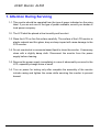
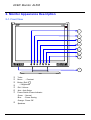
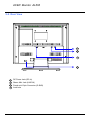
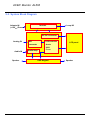
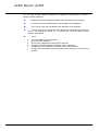
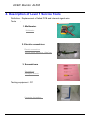
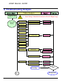
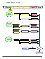
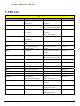
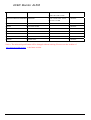
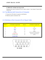
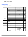
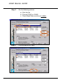
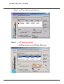
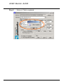
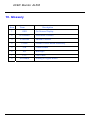
ACER Monitor AL506
- Table of Contents -
1. Attention During Servicing ...........................................................................................................................2
2. Monitor Appearance Description of ProLite E380S .....................................................................................3
2-1. Front View .........................................................................................................................................3
2-2. Rear View...........................................................................................................................................4
2-3. System Block Diagram ......................................................................................................................5
2-4. Explosion Diagram ............................................................................................................................6
3. OSD Menu Screen.........................................................................................................................................8
4. Description of Level 1 Service Tools ..........................................................................................................13
5. Troubleshooting Analysis............................................................................................................................14
6. Level 1 Service Items--MonitorAssembly and Disassembly............................................................................................19
6-1. Remove Stand Bottom .....................................................................................................................20
6-2. Separate Cover (Case Rear Assy) ....................................................................................................20
6-3. Remove FFC ....................................................................................................................................22
6-4. Remove Bezel ..................................................................................................................................22
6-5. Remove lnverter...............................................................................................................................23
6-6. Change New Inverter .......................................................................................................................26
6-7. Remove AD PCBA ..........................................................................................................................29
6-8. Change New AD PCBA...................................................................................................................32
6-9. Change New SW/B (PCB-K)...........................................................................................................35
6-10. Change New SW/B(PCB-K)..........................................................................................................36
6-11. Case Assembly ...............................................................................................................................37
7.FRU ..............................................................................................................................................................41
8. Method for LCD Monitor Testing after Servicing ......................................................................................43
8-1. Test Method Without Connection of Computer...............................................................................43
8-2. Test Method with Connection of Computer.....................................................................................44
8-3. Definition of the Connector Pin of Signal Cable .............................................................................44
8-4. Specification ....................................................................................................................................45
8-5. Factory Mode Function....................................................................................................................47
9.BIOS & OSD Software Update....................................................................................................................48
9-1. Programs: .........................................................................................................................................48
9-2. Tools.................................................................................................................................................48
9-3. Install BIOS Software (Simply way to ROM) & kit: ......................................................................48
9-4. Program Running .............................................................................................................................50
10. Glossary.....................................................................................................................................................54
ACER Monitor AL506
1. Attention During Servicing
1-1. This monitor should be operated from the type of power indicated on the using
label. If you are not sure of the type of power available, consult your dealer or
local power company..
1-2. The LCD shall be placed at low humidity and low dust.
1-3. Place the LCD on firm flat surface carefully. The surface of the LCD monitor is
plastic material and thin glass, drop or sharp impact will cause damage to the
LCD monitor.
1-4. Do not use alcohol or ammonia-based liquid to clean the monitor. If necessary,
clean with a slightly damp cloth. Disconnect the monitor from the power
supply before cleaning.
1-5. Remove the power supply immediately in case of abnormality occurred in the
LCD, especially strange noise of smell
1-6. Turn on power for testing only after complete the assembly of the monitor
include casing and tighten the screw while servicing the monitor to prevent
hazard.
ACER Monitor AL506
2. Monitor Appearance Description
2-1. Front View
1
2
3
4
5
6
7
8
1
2
3
4
5
6
7
Turbo
Menu - / Contrast
Button (Exit / )
+ / Brightness
Exit / Volume
Auto : Auto Setup
Power Switch /Power Indicator
Green
Blue
8
: Normal
: Power Saving
Orange : Power Off
Speakers
ACER Monitor AL506
2-2. Rear View
10
11
12
13
10
11
12
13
DC Power Jack (DC-In)
Stereo Mini Jack (LINE-IN)
D-sub mini 15pin Connector (D-SUB)
Lock hole
ACER Monitor AL506
2-3. System Block Diagram
Adapter IN
(+12VDC) Power
Inverter
Lamp X3
DC-DC converter
Analog IN
A/D
converter
LCD controller
LCD panel
-Scaler
-OSD
Audio IN
Speaker
Audio Amp
-T-con
OSD Keypad
Speaker
ACER Monitor AL506
2-4. Explosion Diagram
1.BEZEL_W/_SPEAKER_
CIRCLE_ASSY
2.OSD PCBA
3.PANEL ASSY
4.PET_FILM_METAL_
FRAM_REAR
5.SMART PCBA
6.INVERTER
7.FFC AD_OSD
8.PET ISOLUTION FILM
9.METAL COVER SMART
10.REAR_STAND_
W/O_TUNER_ASSY
11.SEAT_ELLIPSE_ASSY
12.SCREW
13. SCREW
14. SCREW
15.STAND-OFF
16.SCREW
ACER Monitor AL506
The Table of Explosion Diagram
NUM.
ITEM NAME
CHI-MEI P/N
1
BEZEL_W/_SPEAKER_CIRCLE_ASSY
40A1522923
2
OSD PCBA
35A15K0208
3
PANEL ASSY
44A1513026
4
PET_FILM_METAL_FRAM_REAR
7341391001
5
SMART PCBA
35A15S0203
6
INVERTER
2714000001
7
FFC AD_OSD
3241500001
9
METAL COVER SMART
41A1599115
10
REAR_STAND_W/O_TUNER_ASSY
40A1592966
11
SEAT_ELLIPSE_ASSY
40A1592949
12
SCREW
42A9930001
13
SCREW
42A9920002
14
SCREW
42A9930008
15
STAND-OFF
42A9940007
16
SCREW
42A9930009
ACER Monitor AL506
3. OSD Menu Screen
Press the Menu Button to start the On Screen Display feature. There are additional
Menu pages which can be switched by using the +/–Buttons.
Operate
Explanation
V-Position
50
Displayed while Turbo is active
Displayed while Mute is active
Page no.
Adjustment icon
Current horizontal frequency,
vertical refresh rate and
resolution
Select the Menu page that contains the adjustment icon relating to the adjustment
you want to make. Press the Menu Button again. Then, use the +/– Buttons to
highlight the desired adjustment icon. Press the Menu Button again.
Use the +/–Buttons to make the appropriate adjustment or setting.
For example, to correct for vertical position, select Menu page number 1 and then
press the Menu Button. Then, select (V-Position) by using the +/– Buttons.
An adjustment scale appears after you press the Menu Button. Use the +/– Buttons
to change the vertical position settings. The vertical position of the overall display
should be changing accordingly while you are doing this.
The bar shows the progress of the
adjustment being made
ACER Monitor AL506
The On Screen Display disappears several seconds after you stop pressing the
buttons while performing an adjustment.
Notes
Any changes are automatically saved in the memory when the On Screen Display
disappears. Turning off the power should be avoided while using the Menu.
Adjustments for Clock, Phase and Position are saved for each signal timing. Except
for these adjustments, all other adjustments have only one setting which applies to
all signal timings.
Adjust
Pressing [+] , [-] or [Menu] buttons for the adjustment when the OSD is executed.
Menu contents
Menu: 1
Brightness*1 (Direct)
Contrast (Direct)
Clock
Phase
H-Position
Return to Menu
V-Position
*1 Adjust the Brightness when you are using the monitor in a dark room and feel the
screen is too bright.
Note: SWITCHING BRIGHTNESS /CONTRAST ADJUSTMENT:
To switch between Brightness and Contrast adjustments, press the Menu Button within 10
seconds after pressing the Brightness Button or the Contrast Button during the direct
adjustments above.
ACER Monitor AL506
Menu: 2
Auto Set-up*1 (Direct)
Color Temp.
Sharpness
Return to Menu
*1 For best results, use the Auto Set-up in conjunction with the adjustment pattern. And
the screen becomes dark for approximately five seconds during the adjustment.
Note:
Auto Set-up Setting:
No: The Auto Set-up is not performed when the signal input is changed.
Yes: Adjust Clock and Phase automatically when the signal input is changed.
Color Temp.: Color 1: 9300K; Color 2: 7500K; Color 3: 6500K; sRGB: User
sRGB is an international standard which defines and unifies the difference of
color appearance between equipment.
Sharpness: Adjust the picture quality at resolutions of less than 1024 × 768. You
can change the picture quality from 1 to 5 (sharp to soft). Press the + Button to
change the picture quality in numerical order. Press the – Button to change the
picture quality in reverse numerical order.
ACER Monitor AL506
Menu: 3
Volume (Direct)
OSD Position
Language
Return to Menu
Reset
Note:
OSD Position: You can move the OSD display area to any one of the following
5 positions within the overall display:
1
4
3
2
5
Press the + Button to move the OSD in numerical order. Press the – Button to move
the OSD in reverse numerical order.
Language: Eng: English; Dth: German; Fns: French; Ity: Italian; Epl: Spanish;
Jpn: Japanese; T-C: Tranditional Chinese; S-C: Simplified Chines
ACER Monitor AL506
Direct
You can skip the Menu pages and display an adjustment scale directly by using the
following button operations:
Brightness: Press the Brightness Button when the Menu is not displayed.
Contrast: Press the Contrast Button when the Menu is not displayed.
Auto Set-up: Press the Auto Button when the Menu is not displayed.
Volume: Press the Volume Button when the Menu is not displayed. When OSD
menu is off, holding this button for 1-2 seconds will switch the Mute function
between ON and OFF.
Turbo:
Pct: Picture Mode (High brightness)
Text: Text Mode (Normal)
Eco Economy (Brightness of back-light is reduced)
Changing to a lower brightness mode can lessen eye fatigue.
Change from Picture Mode to Text Mode when working with text.
Change from Text Mode to Economy Modes when viewing the screen for long
periods.
ACER Monitor AL506
4. Description of Level 1 Service Tools
Definition : Replacement of failed PCB and internal signal wire.
Tools
:
1. Multimeter.
Multimeter
2. Electric screwdriver.
Electric screwdriver
Torque value: adjust to 1.5kgf*cm
3. Screwdrivers
Screwdriver
Hexagon Wrench
Testing equipment : PC
Computer for testing :
ACER Monitor AL506
5. Troubleshooting Analysis
Defect Mode
Failure Analysis
Light On Test
Repair
Testing
※ “ Panel Change” Should be Performed to Level 3 Repair stage
Missing Line
Abnormal
Display
Bright Dot
Check PCB
AD/B Change
Check Panel
Panel Change
Check Panel
Panel Change
Dark Dot
Backlight
Light Leakage
Mura
Image Sticking
Brightness spot
Particle
Dot Defect
No display
Check PCB
AD/B Change
Inverter Change
Noise
Check Panel
Panel Change
Check PCB
AD/B Change
Check Panel
Panel Change
NG
Next Step
A
TEST
Completed
ACER Monitor AL506
Defect Mode
Failure Analysis
Repair
Testing
※ “ Panel Change” Should be Performed to Level 3 Repair stage
A
Flicker
Check PCB
AD/B Change
Inverter Change
Check OSD
Gray value
display
R.G.B display
Adjust VCOM
Check PCB
AD/B Change
Check Panel
Panel Change
Check PCB
AD/B Change
Check PCB
AD/B Change
abnormal
Display Shut
Down
No signal
Power on
Display
Inverter Change
Check Panel
Panel Change
Check PCB
AD/B Change
Check PCB
AD/B Change
abnormal
NG
Next Step
A
TEST
Completed
ACER Monitor AL506
Defect Mode
Failure Analysis
Repair
Testing
※ “ Panel Change” Should be Performed to Level 3 Repair stage
ON/OF
Abnormal
No Power
Check PCB
SW/B Change
Check Wire
LED display
abnormal
AD/B Change
AD/B Change
LED Off
LED Dark
FFC Change
Check PCB
SW/B Change
LED Abnormal
Check Wire
FFC Change
Check PCB
AD/B Change
LED Flicker
Abnormal
Keyboard
Unavailable
SW/B Change
Check Wire
FFC Change
NG
Next Step
TEST
Completed
ACER Monitor AL506
Defect Mode
Failure Analysis
Repair
Testing
※ “ Panel Change” Should be Performed at Level 3 Repair stage
Abnormal BIOS
Can’t Input
&OSD
Check PCB
AD/B Change
Check PCB
AD/B Change
Can’t Read
Other Abnormal
Display
Display Shut
Down
Display flicker
Inverter Change
Check Panel
Panel Change
Check PCB
AD/B Change
(tapping )
Check Panel
Next Step
Inverter Change
NG
TEST
Completed
ACER Monitor AL506
Defect Mode
Failure Analysis
Repair
Testing
※ “ Panel Change” Should be Performed at Level 3 Repair stage
Audio
Abnormal
Sound adjust
abnormal
No sound
Single sound
Check PCB
AD/B change
Check speaker
Speaker change
Check FFC
FFC change
Check PCB
AD/B change
SW/B change
TEST
Completed
ACER Monitor AL506
6. Level 1 Service Items--Monitor Assembly and Disassembly
The flow of Monitor assembly and disassembly procedure as below :
※ Must to protect the Polarizar Scratch
※ Must to protect ESD issue
1
Separate Stand
2
Separate Cover
3
Remove Inverter
4
Change Inverter
5
Remove AD PCBA
6
Change AD PCBA
7
Cover Assembly
8
Stand Assembly
ACER Monitor AL506
6-1. Remove Stand Bottom
Step 1 -
Press the hooks and
remove the Seat
Step 2 - Completed
6-2. Separate Cover (Case Rear Assy)
Step 1 - Rotate the Stand Hinge and
lay it down
ACER Monitor AL506
Step 2 - Loose & Remove 5 screws
Screw P/N : 42A99300009
Screwdriver : #2-0.7mm
Step 3 - Remove Rear Case from
Bezel
Step 4 - Lift up Rear Case
Step 5 - Completed
ACER Monitor AL506
6-3. Remove FFC
Step 1 - Pull out FFC from connectors
at Switch Board and AD
PCBA
Step 2 - Completed
6-4. Remove Bezel
Step 1 - Lift up LCD module and Remove
Bezel
Step 2 - Completed
ACER Monitor AL506
6-5. Remove lnverter
6-5-1. Remove Metal Cover
Step 1 - Loosen & Remove 2 Stand-Off screws
Stand-Off Part No : 42A9940007
Step 2 - Loosen & Remove the screw
Screw Part No : 42A9930008
Screwdriver : #2- 0.7mm
Step 3 - Loosen & Remove 3 screws
ACER Monitor AL506
Step 4 - Open & Separate Metal Cover (PCB-X)
with tool
Step 5 - Push Metal Cover (AD/Power-PCB)
Step 6 - Completed
6-5-2. Remove 3 B/L Wire
ACER Monitor AL506
6-5-3. Loosen & Remove 3 Screws
6-5-4. Remove Inverter
Step 1 - Lift up Inverter slightly
Step 2 - Shift Inverter with care ;
Separate its head from the
housing at AD PCBA
Step 3 - Take Inverter apart ;
Completed.
ACER Monitor AL506
6-6. Change New Inverter
New Inverter
Step 1 - Shift Inverter with care ; plug
its head into the housing at
AD PCBA.
Step 2 - Carefully lay down Inverter
Step 3 - Fasten 3 screws to fix inverter
ACER Monitor AL506
Step 4 - Insert Backlight wires
Step 5 - Place Metal Cover (AD/Power-PCB)
Step 6 - Place Metal Cover (PCB-X)
Step 7 - Push the metal Cover (PCB-X)
Forward to have the hook
Latched.
ACER Monitor AL506
Step 8 - Fasten 3 screws
Step 9 - Fasten the screw
Step 10 - Fasten 2 Stand-Off screws
Step 11
- Completed
ACER Monitor AL506
6-7. Remove AD PCBA
6-7-1. Remove Metal Cover (SMART & PCB-X)
Step 1 - Loosen & Remove 2
Stand-Off screws
Stand-Off Part No :
42A9940007
Step 2 - Loosen & Remove the screw
Screw Part No : 42A9930008
Screwdriver : #2- 0.7mm
Step 3 - Loosen & Remove 3 screws
ACER Monitor AL506
Step 4 - Open & Separate Metal Cover (PCB-X)
Step 5 - Push Metal Cover (AD/Power-PCB)
Step 6 - Completed
6-7-2. Remove AD PCBA
Step 1 - Remove the taps on X-board FPC
ACER Monitor AL506
Step 2 - Pull out the X-Board FPC
Step 3 - Loosen & Remove 4 screws
Step 4 - Shift AD PCBA with care ;
Separate its housing from head
Step 5 - Take AD PCBA apart
ACER Monitor AL506
Step 6 - Completed
6-8. Change New AD PCBA
AD PCBA
Step 1 - Place new AD PCBA
Step 2 - Shift AD PCBA with care ;
join its housing with head at
Inverter
Step 3 - Fasten 4 screws
ACER Monitor AL506
Step 4 - Insert FPC to connector
Step 5 - Place Metal Cover (AD/Power-PCB)
Step 6 - Place Metal Cover (PCB-X)
Step 7 - Push the metal Cover PCB-X
Forward to have the hook
latched.
ACER Monitor AL506
Step 8 - Fasten 3 screws
Step 9 - Fasten the screw
Step 10 - Fasten 2 Stand-Off screws
Step 11 - Completed
ACER Monitor AL506
6-9. Change New SW/B (PCB-K)
Bezel Assy (W/ AUDIO)
Step 1 - Separate both Audio Cables
Step 2 - Loosen & Remove 2 screws
Step 3 - Take SW/B (PCB-K) apart ;
completed
ACER Monitor AL506
6-10. Change New SW/B(PCB-K)
Step 1 - Place new SW/B (PCB-K)
Step 2 - Fasten 2 screws
Step 3 - Insert Audio Cable to Connectors
Step 4 - Completed
ACER Monitor AL506
6-11. Case Assembly
6-11-1. Join Bezel with LCD module.
Before Assembly
Step 1 - Place LCD module
Step 2 - Completed
6-11-2. Insert FFC
Step 1 - Insert both sides of FFC
into connectors
ACER Monitor AL506
Step 4 - Completed
6-11-3. Rear Case Assembly
Before Assembly
Step 1 - Place Rear Case
Step 2 - Fasten 5 screws
ACER Monitor AL506
Step 3 - Completed
6-11-4. Stand Assembly
Before Assembly
Step 1 -Rotate & lift up Stand Hinge
Step 2 - Place Seat
ACER Monitor AL506
Step 3 - Have the hook latched
Step 4 - Completed
ACER Monitor AL506
7. FRU List
FRU
CATEGORY
PARTNAME
DESCRIPTION
PART NO.
ADAPTER
ADAPTER 4A 48W 3PIN POTRANS
ADAPTER (AC/DC) , 48W,12V,4A
25.L03VG.001
UP04821120A-16
UP04821120A
FUNCTION BUTTON BOARD
PCBA FOR
BOARDS
55.L03VG.001
A150X2,A150X2-K,X8,RIGID,201-0A
BOARDS
INVERTER BOARD SUMIDA
INVERTER BOARD SUMIDA
TWS-444-936
TWS-444-936,
55.L03VG.002
TYP.2400V/5MA,SUMIDA
LCD
LCD MODULE 15 IN. TFT CHI-MEI
6M.L03VG.001
W/LCD BRACKET
LCD
LCD MODULE 15 IN. TFT CHI-MEI W/O
6M.L03VG.002
BRACKET
CABLES
CABLES
FUNCTION BUTTON BOARD
FFC AD-OSD UNITE-STAND
CABLE-FFC 128MM
128*9.5MM
AUDIO CABLE
AUDIO CABLE A150X1-T01,28A
50.L03VG.001
50.L03VG.002
WG,180CM
CABLES
SIGNAL CABLE
MONITOR
50.L03VG.003
CABLE,A150X1-T01,30AWG,180CM
CABLES
POWER CORD 125V 3PIN US
27.L03VG.001
CABLES
POWER CORD 250V 3PIN UK
27.L03VG.002
CABLES
POWER CORD 3 PIN SWISS
27.L03VG.003
CABLES
POWER CORD 3 PIN PRC
27.L03VG.004
CABLES
POWER CORD 250V 3PIN EC
27.L03VG.005
CABLES
POWER CORD 3PIN JAPAN
27.L03VG.006
CABLES
POWER CORD 3PIN AUSTRIAL
27.L03VG.007
MAINBOARD
AL506 MAINBOARD
PCBA FOR A
( FIRMWARE CONTROL BOARD )
150X2-S,X7,RIGID,201-07
CASE/COVER/BRACKET/ASSEMBLYSTAND BASE
55.L03VG.003
SEAT ASSY(ELLIPSE) A150X2-T04 60.L03VG.001
ABS ORIGIN
CASE/COVER/BRACKET/ASSEMBLYLCD FRONT BEZEL
BEZEL ASSY ( CIRCLE ) A15X2-T04 60.L03VG.002
ABS W/SPEAKER ORIGIN
CASE/COVER/BRACKET/ASSEMBLYLCD BACK COVER W/STAND NECK
REAR AND STAND-HINGE ASSY
A150X2-R04ABS ORIGIN
60.L03VG.003
ACER Monitor AL506
CASE/COVER/BRACKET/ASSEMBLYMAINBOARD COVER
METAL COVER AD/POWER-PCB
33.L03VG.001
A150X2 TIN PLATE t=0.4MM
CASE/COVER/BRACKET/ASSEMBLYLCD BRACKET
METAL COVER PCB-X, A150X2,
33.L03VG.002
TIN PLATE, t=0.4MM
SCREWS
FUNCTION BUTTON BOARD SCREW
86.L03VG.001
SCREWS
BACK COVER SCREW
86.L03VG.002
SCREWS
INVERTER/MB SCREW
86.L03VG.003
SCREWS
M/B COVER SCREW
86.L03VG.004
SCREWS
LCD BRACKET SCRWE
86.L03VG.005
SPEAKER
SPEAKER LEFT
23.L03VG.001
SPEAKER
SPEAKER RIGHT
23.L03VG.002
Notice: The aforesaid specification will be changed without noticing. Plz access to the website of
http://aicsl.acer.com.tw/spl/ for the latest version.
ACER Monitor AL506
8. Method for LCD Monitor Testing after Servicing
※ After exchange PCBA (A/D, Inverter) The Monitor should be performed run-in for 4 hours
8-1. Test Method Without Connection of Computer
1. Method to start run-in mode
Step 1.
Remove the VGA cable
Step 2.
Press the ”Auto”, ”―”,
+
” ” simultaneously
Step 2 - Red
Step 1 - White
2 seconds
2 seconds
Step – 2 Red
2 seconds
Step 3 - Green
Step 4 – Blue
Step
Step 55 -–Black
Black
2 seconds
2 seconds
ACER Monitor AL506
2. Method to release burning mode
There are two ways to release the run-in mode: namely: 1. input signal; 2. press down
Power key.
8-2. Test Method with Connection of Computer
1. Connect the VGA cable of computer to the Monitor.
2. Windows system environment test.
8-3. Definition of the Connector Pin of Signal Cable
Pin No.
15-Pin side of signal cable
Pin No.
15-Pin side of signal cable
1
2
3
4
5
6
7
8
Red
Green
Blue
NC
Ground
9
10
11
12
13
14
15
NC
Ground
NC
(SDA)
Horizontal synchronization
Vertical synchronization
(SCL)
Ground -red
Ground -green
Ground -blue
ACER Monitor AL506
8-4. Specification
8-4-1. General Specification:
Item
Specification
Unit
304.1 (H) x 228.1(V) (15.0” Diagonal)
mm
a-si TFT Active Matrix
-
Pixel Number
1024 x R.G.B. x 768
pixel
Pixel Pitch
0.297 (H) x 0.297 (V)
mm
RGB Vertical Stripe
-
16.2M
color
Normally White
-
120 / 110
degree
Brightness
350
cd/m2
Contrast Ratio
450
-
23 (Tr: 6 + Tf: 17)
msec
TTL Level
-
Positive / Negative
-
Vertical Sync.
Positive / Negative
-
Input Connector
D-Sub mini 15 pins
-
AC100~240 (Worldwide)
V
Power Output
12
VDC
Operation Mode
33
W
Power Saving Mode
3
W
30 / 0
degree
365.4(W) x 339.9(H) x 181.0(D), 2.6
mm, kg
DDC 1/2B Compliance
-
7keys
-
Active Area
Driver Element
Pixel Arrangement
LCD panel
Display Color
Tran missive Mode
Viewing Angle (Horizontal / Vertical)
Response Time (Tr+Tf)
Separate Sync.
Graphic
Power source
Power consumption
Horizontal Sync.
Power Input
Tilt angle
Upward / Downward
Physical
Dimension, weight
DCC
Plug & Play
Front key
Picture Mode: 350
Function
Turbo (Brightness Selection)
TEXT Mode: 200
cd/m2
Economy Mode: 140
Audio & Speaker
Yes
-
ACER Monitor AL506
8-4-2. Electrical Specification:
Item
Video Signal
Synchronization Signal Input System
Description
Input System
RGB Separate
Signal Level
Analog RGB: 0.7VP-P
Input Impedance
75Ω
Signal Level
Separate Sync: TTL
Compliant Timing
See Appendix 1.
Input Connector
D-Sub mini 15 pins
Video Frequency Bandwidth
80MHz dot clock
Audio
d=3.5mm stereo mini jack, 1.5W/ch
Synchronization Frequency
Horizontal Sync.
28~63 kHz
Vertical Sync.
55~78Hz
Input Voltage
AC100~240V (Worldwide)
Frequency
50 / 60Hz
Power Supply
Power Consumption
Power Management
Lamp Type
Lamp Quantity
Backlight
Lamp Life Time
33W (max)
3W (max)
Cold Cathode Fluorescent Lamp
3pcs
40,000Hrs (min)
Plug & Play
VESA DDC 1/2B Compliance
Power Management
VESA DPMS, ENERGY STAR® Compliance
Notice: the aforesaid specification will be changed without noticing *refer to standard signal mode.
ACER Monitor AL506
8-5. Factory Mode Function
1.
2.
3.
The time to use: After changing AD PCBA , Inverter.
Connect to PC
Press “+”, “-”, “AUTO” simultaneously to start Factory Mode.
BIOS number
Time, Date, Year
AUTO
F1
and F2
4.
Then, press the “+”, “-” Buttons to switch between
5.
To run Auto Balance, please have highlighted
The screen will show the box as below:
6.
To run VCOM adjust, please have highlighted F2
and press “Menu” bottom.
Press the “+”, “-” Button to make the appropriate adjustment or setting.
F1
.
and press “Menu” bottom.
ACER Monitor AL506
9.BIOS & OSD Software Update
9-1. Programs:
1、
2、
3、
4、
5、
FlashupgradeNT.exe
Flesher.hex
P15014B001.hex
P15014B001.inf
P15014B001.ini
9-2. Tools
a.
b.
c.
d.
ISP Kit (Prepared by CMO); refer fig 1.
RS232 Comport Cable (Prepared by Agent); ref fig 2.
D-sub cable (Original Assy)
Adapter (Original Assy)
Fig 1 - Kit
Fig 2 – RS232
9-3. Install BIOS Software (Simply way to ROM) & kit:
※ Please power off the monitor.
9-3-1. Install BIOS :
FlashUpgraderNT.exe
ACER Monitor AL506
9-3-2. Kit equipped:
Step 1 - Get a kit
Step 2 - Join R232, monitor cable, and adapter.
Connect PC
Connect to adapter
Connect monitor
Step 3 - When the LED turns red, it will start running.
ACER Monitor AL506
9-4. Program Running
Step 1 - the indicated program : Flash Upgrade NT.exe
ACER Monitor AL506
Step 2 - Do the following actions:
a. Click the file
b. Choose COM1 or COM2
c. Check Band Rate must be at 115200
Step 3 - Click the bottom of Flash
ACER Monitor AL506
Step 4 - Then it will show below box.
Step 5 - a) Power on monitor.
b) After power on, it will start flash rom.
ACER Monitor AL506
Step 6 - Notice of Flash completed.
ACER Monitor AL506
10. Glossary
Item
Term
Description
1
OSD
On Screen Display
2
H-Position
Horizontal Position
3
V-Position
Vertical Position
4
PCBA
5
P/B
Power Board
6
B/L
Backlight
7
FPC
Flat Cable
8
AD-Board
Printed Circuit Board Assembly
Analog to Digital Board