1
VPA-S001
(RCS PONTOISE B 338 101 280)
Jook Jin Won Saek Print Co.
109, Cho-dong, Jung-gu,
Seoul, Korea
68P11199Y15-A
Printed in Korea (Y)
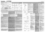
CD/Video CD Changer
ß OWNER'S MANUAL
Guide for Installation and Connections/ !"#$
Accessories/ Please read this manual to maximize your enjoyment of the outstanding performance and feature
capabilities of the equipment, then retain the manual for future reference.
English
ß !"#
!"#$%&'()*+,-./%#0123456789:6;<=>?@A)BC
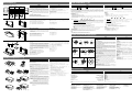
CD/VIDEO
HIGH
CD
×4
×2
×2
×2
Hexagon Flange-head
Screws (M5x15)
"L" Type Brackets
(For Vertical Mounting)
"L" Type Brackets
(For Horizontal Mounting)
!"#$jR NR
i= !"#$%
i=
×8
Hexagon Flange-head
Nuts (M6)
Floor Base Plates
!"#$%
!"#$jS
COMPATIBLE
SPEED
DISC
CHANGE
×1
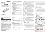
CD/VIDEO CD CHANGER
OPEN
×4
IMPORTANT
Please record the serial number of your unit in
the space provided here and keep it as a permanent record. The serial number plate is located
on the top of the unit.
×4
×4
Hexagon Bolts (M6 x 25)
!jS OR
Hexagon Washer-head
Bolts (M4 x 8)
!"#$jS RM
≠
≠
≠
Meaning of displays
≠
Warning
This label is intended to alert the user to the presence of important operating
instructions.
Failure to heed the instructions will result in severe injury or death.
Caution
This label is intended to alert the user to the presence of important operating
instructions.
Failure to heed the instructions can result in injury or material damage.
!"#$%&'
×1
×1
×1
Dust Cover Label (L/R)
Input/Output Label (L/R)
CD Magazine
Index Label Sheet
^áJkbq=
!" L L ! L `a=
!"
×3
×1
CAUTION:
Do not install the Shuttle near the vehicle’s fuel tank. This will prevent the
mounting screws from damaging the tank.
×2
VOCAL Switch
Mount Base
RCA extension cable
Velcro tape
sl`^i=
o`^= !
!"
Read this manual carefully before starting operation and use this system safely. We cannot be
responsible for problems resulting from failure to observe the instructions in this manual.
This manual uses various pictorial displays to show how to use this product safely and to avoid harm
to yourself and others and damage to your property. Here is what these pictorial displays mean.
Understanding them is important for reading this manual.
Plastic Bag for Shipping
Screws
Ai-NET Cable
×1
≠
Binder
!"#$jQ U
×1
×1
Points to Observe for Safe Usage
×1
Hexagon Flange-head
Bolts (M6 x 50)
!"#$%&'()*+,-./0123 !"#$%&
SERIAL NUMBER/ !
INSTALLATION DATE/ !"
INSTALLATION TECHNICIAN/ !"#
PLACE OF PURCHASE/ !
≠
’Before Installation
Perform the installation at a location that is level. Make sure the parking
brake is on and the ignition is OFF.
Refer to the Connections and Operation sections before you proceed
with installation.
Install the Shuttle properly using the “L” type brackets supplied. Improper installation can degrade performance (causing the player to skip,
mis-track, etc.).
Install the Shuttle in the trunk of the car or another suitable location. In
the passenger compartment of some cars, the glove box, under the dash
or center console may be able to accommodate the VPA-S001. Make sure
that the installation will not interfere with the safe operation of the vehicle or with passenger leg room.
The VPA-S001 should be mounted to a stable surface. If no stable surface
is available, you must build a mounting board for the Shuttle. Choose a
location which allows easy access to insert and remove the CD magazine. Determine the mounting location and position. Then have the
necessary parts ready before you begin installation.
NOTE:
For the vertical installation be sure to install the Shuttle with the CD
magazine slot facing upward.
Installation of Shuttle
With the VPA-S001, CDs are automatically removed from and reinserted
into the CD magazine, DO NOT mount the unit upside down, as this could
cause the mechanism to become misaligned.
Never install the Shuttle on the rear deck or front dashboard of the car.
The temperatures caused by direct sunlight at these locations can reach
extremes that could cause permanent damage to the Shuttle. The Alpine
Warranty will be voided in cases where this caution has been ignored
and results in damage to the Shuttle.
!"#$%&'(
!"#$%&'()*+,-. !"#$%& !"#$%&'()%&*+,)-./012
!"#$%&'() *+,-#$./0123456789:04#3;<.1=>? !"#$
!
!"
!"#$%&'()
!"#$%&'(
!"#$%&'()*+
(H)
!"#$!%&'()*+,-./0
V
!"#$%&'()*+,-.
(V)
22.5°
Warning
H
V
DO NOT DISASSEMBLE OR ALTER. Doing so may lead to accident, fire or electric shock.
!"#$%&
KEEP SMALL ARTICLES OUT OF THE REACH OF CHILDREN. If swallowed, consult a physician immediately.
!"#$
!"#$%
!"#$%&'
BEFORE WIRING, DISCONNECT THE CABLE FROM THE NEGATIVE (–) BATTERY TERMINAL. Failure
to do so may result in electric shock or injury due to electrical shorts.
!"#$
!"#$%&'()
!"#$%&'()*+,-./0"
!"#$%&'()*+,-./0123456
MAKE THE CORRECT CONNECTIONS. Failure to do so may cause fire or accident to occur.
DO NOT CUT AWAY THE WIRE SHEATH AND USE POWER FOR OTHER EQUIPMENT. Doing so may
exceed the current carrying capacity of the wire and result in fire or electric shock.
DO NOT INSTALL IN LOCATIONS WHICH MIGHT HINDER VEHICLE OPERATION OR CREATE
HAZARDS FOR VEHICLE OCCUPANTS. Doing so may obstruct forward vision or hamper movement.
DO NOT CONTACT, DAMAGE OR OBSTRUCT PIPES, FLUID LINES OR WIRING WHEN DRILLING
HOLES. Failure to take such precautions may result in fire or cause an accident or injuries.
DO NOT USE NUTS OR BOLTS IN THE BRAKE SYSTEM WHEN MAKING INSTALLATION OR GROUND
CONNECTIONS. Never use safety-related parts such as bolts or nuts in the steering or brake
systems or tanks to make wiring installations or ground connections. Using such parts could disable
control of the vehicle and cause brake failure, other accident or injury.
ARRANGE THE WIRING SO IT IS NOT CRIMPED OR PINCHED. Route the cables and wiring so as
not to be crimped by moving parts or make contact with sharp or pointed spots which might damage
the wiring. Failure to do so may cause failure of unit or vehicle.
HAVE THE WIRING AND INSTALLATION DONE BY EXPERTS. The wiring and installation of this unit
requires special technical skill and experience. To ensure safety, always contact the dealer where
you purchased this unit to have the work done.
!"#$%&'
%&'()*+,
!"#$%
90°
!"#$
!"#
!"#$%&'$()*+,-./012$3
!"
!"#$%&'()
!"#$%&
!"#$%&$'( !"#$%&'()'* !"#$%&'(&)* !"#$%
!" !" !"#$%&'("') !"#$%&'()*+,)-&./0123
!
!"#$%&'
!"
!"=i= !"#$% !"#$%&'$()*+, -./0
!"
!"#$%&'()*+,-./01 !"#$%&'()*+, !"#$%&'()=sm^JpMMN=
!"#$%&'()*+,-./0123'45
sm^JpMMN= !"#$%&'()*+,#$-.'/0123456789
! =`a= !"#$%&'(
!"#$%& !'()*+,-./
!"#$%&'=`a= !"#$
!"
sm^JpMMN= !"=`a=
!"#$%&'
!"#$=`a=
!"#$%&'()*
!"#$%&'()*+,-./012345678*+
!"#$%&'()*+,-./0123 !"#$%&'()*+
!"#$%&'()*+ !"#$%&'()*+,-./0123
Shipping Screws
Three screws have been attached to the bottom of the Shuttle for protection during shipment. Remove these screws before using. Keep the
removed screws in the plastic bag attached to the connector of Shuttle.
!"
!"#$%&'()*=P=
!"#$%&'(
Mounting in the Trunk
Make sure the mounting angle of the Shuttle installation will fall within the
five preset positions (22.5˚ to 45˚ from the horizontal or vertical position). The
Shuttle is preset at the factory for horizontal mounting. If you wish to install
it at any other angle, change the spring configuration as shown.
1. Remove the covers provided at both left and right sides of the unit by
pressing claws of the covers in the direction shown by the arrow.
2. Change the position of the spring with your finger.
Use the figure to determine which spring position would be best suited for
your chosen mounting location. If the spring configuration is incorrect or
the spring positions on the left and right sides are not the same, the shock
absorbing mechanism will not function properly. This will prevent the CD
Shuttle from operating at its best.
3. Mount the covers at the left and right sides as they were attached originally.
!"#$
!"#$%=R= !" #$%&'()*+,-./0123=OOKR=
=QR= !"#$%&'()*+ !"#$%&'()*+,
!"#$%
NK !"#$%&'()*+,-./0&'
OK !"#$%&
!"#$%&'()*+,-"./012
!"#$%&'()* !"#$+,-./0#1$2345678 !"#$%&'()*+,
PK !"#$%&'()*+,-.
’ Parts identifications
1 Bus Selector Switch (Fig. 1)
This switch is used to select Ai-NET or Standard-Bus operation. Change
the switch position using a small screwdriver or other pointed object.
Ai-NET system
Standard-Bus System
’ !
1 !"#$%=N
Ai Std.
1
Fig. 1
!"#$%&'()!*+$,-
!"#$ !"#$ !"#$%&'( !"#$%
! !"#$%&'()* !"#$%&'()
!"#$%&'()*+,
!"#$%&'(
!"#$%&'()*+,
!"#$%&'%(
!"#$%&'()*+
!"#$%&'($)*
!"#$
!"#$%&
Fig. 2
!"#$%&'()
!
!"
=O
Ai Std.
!"#$%
!"#$%
4
6
2
VPA-S001
!"#$%&
'()#*+
5
!
Fig. 3
HALT USE IMMEDIATELY IF A PROBLEM APPEARS. When problems occur such as a lack of sound
or video, foreign objects inside the unit, smoke coming out, or noxious odors, stop use immediately
and contact the dealer where you bought the equipment. Failure to do so may result in an accident
or injury.
!"#$%
!"#$%&'()*
Ai Std.
8
2
DO NOT OPERATE THE EQUIPMENT OR LOOK AT THE SCREEN WHILE DRIVING THE VEHICLE.
Operating the equipment may distract the driver from looking ahead of the vehicle and cause
accident. Always stop the vehicle in a safe location before operating this equipment.
9
Fig. 4
DO NOT USE THIS EQUIPMENT FOR PURPOSES OTHER THAN STATED FOR THE VEHICLE. Failure to
do so may result in electric shock or injury.
0
=Q
@
OUT
VPA-S001
DO NOT PLACE FOREIGN OBJECTS IN INSERTION SLOTS OR GAPS. Do not insert hands, fingers
or foreign objects in the disc or cassette insertion slots, or in gaps during monitor startup/storage.
Doing so may result in personal injury or damage to the equipment.
%
#
OUT
!
^
NTSC
IN
PAL
Fig. 5
$
’ Connections
Ai-NET Connection (Fig. 3)
• Bus Selector Switch: Set to "Ai" position.
4 Ai-NET Connector
5 Head unit, etc. with Ai-NET System
6 Ai-NET Input Connector
Switch Connections (Fig. 5)
0 Switch Connector
@ VOCAL Switch (Included)
When attaching the switch, be sure to clean off dust, water drop and
oil on the spot where the switch is attached. The connection cables
should be securely fixed using the provided Mount Base.
7
VPA-S001
Connecting to TV Monitor (Fig. 5)
! VIDEO Output Connector
# RCA Extension Cable (Included)
$ To VIDEO Input Terminal
% TV Monitor
^ VISUAL Switch
Place the Visual switch in the desired TV system position, NTSC or PAL.
Change the switch position using a small screwdriver or other pointed object.
NTSC
=R
NTSC
USE SPECIFIED ACCESSORY PARTS AND INSTALL THEM SECURELY. Use of other than designated
parts may damage this unit internally or may not securely install the unit in place as parts that come
loose may create hazards.
!"#$%&'&( !"#$%&'()*+,%-./0)123456- %&789:
DO NOT INSTALL IN LOCATIONS WITH HIGH MOISTURE OR DUST. A high incidence of moisture or
dust that penetrates into this unit may cause smoke or fire.
!"#$#%&'(
!"#$%&'()*
+,-./01234)56
=S
!"#$=^áJkbq= !"#$
!"#$%&'()*+,-./012
^áJkbq=
!"#
NTSC
Ai Std.
!"#$%&'()*+,-./0=sm^JpMMN=
2 ^áJkbq= !"#=sm^JpMMN= !"=O
=^áJkbq= !"#$%=^äéáåÉ=^áJkbq= =`a= !"#^áJ
kbq= =i= !"#$%&'()*+ #$%=sm^JpMMN=
3 !"#$%&'=O
^áJkbq= !"#$%!"#&'#$()*+,'#&()*-,
!"#$%&'()*(+,-./01'23
^áJkbq= !=P
!"#$%&'^á
4 ^áJkbq=
5 =^áJkbq= !"#$%
6 ^áJkbq= !
!"#$%=Q
= !"#$%&'píÇ
4 ^áJkbq=
7 !"#$%&'()*
8 U==afk= !
9 !"#$%&'()*
!"#=R
0 !
@ sl`^i= !"#$%&'
!"#$%&'()*+,-./0#12345678)9:
!"#"$%&=R
! =EsfablF= !
# o`^= !"#$%&'()
$ !=EsfablF= !
% !
^ !
!"#$%&'()*!+,-./kqp`==m^i
!"#$%&'()*+,-./012
PAL
PAL
NTSC
PAL
’ Cautions for Connections
• Head unit with Ai-NET capability and Ai-NET Cable (Fig. 6)
Connect the Ai-NET cable as illustrated.
Fig. 6
Ai Std.
Mini-Bus Connection (Fig. 4)
• Bus Selector Switch: Set to "Std." position.
4 Ai-NET Connector
7 Head unit, etc. with Standard-Bus System
8 8 pin DIN Input Connector
9 Standard-Bus Adaptor (Sold Separately)
=P
4
Ai Std.
CAUTION:
When switching the Bus Selector Switch, make sure there are no cables
attached to the VPA-S001.
2 Ai-NET Cable (Included in the VPA-S001) (Fig. 2)
The Ai-NET Cable provided, allows connection to any Alpine Ai-NET compatible, CD Shuttle Controller. Make sure that the "L" type connector of
the Ai-NET cable is attached to the Controller and the straight connector
is attached to the VPA-S001.
3 Input/Output Identification Label (Fig. 2)
The Ai-NET system has an input and an output. The input connectors are
Gray and outputs are Black. Use the corresponding Input/Output ID labels to maintain proper connections when extension cables are used.
2
!"#$%&'()
!" L =N
3
!"#$%&'() !"#$%&'()*+,-./012345(678$"9:;<
!"#$%&'(
Caution
!"#$%&'()*+%,-./$0
!"#$%&'()*+,
!"#$%&'()*+,
!"#$%&'()
!"#$%&"'
0°
67.5°
!"
!"#$%&
0°(H)
45°
R
90°
(V)
!"#$!%&'()*+,-./0
H
’
• Connect the cables by referring to the illustration. Incorrect connection may cause damage.
• Check the cables and read the attached labels carefully.
NTSC
PAL
PAL
NTSC
PAL
!"#
=^áJkbq= !"#$%=^áJkbq= !=S
!"#=^áJkbq=
!"#$% !"#$%&'(
!"#$%&'()*+
INSTALLATION/ Video CD Operation/s=`a=
L-Bracket Hole Application Chart/i= !"#
4
4
3
3
2
2
1
1
English
Vertical/ Diagonal/ Horizontal/ Yes/ No/ Yes/ No/ No/ Yes/ No/ Yes/ No/ No/ 4
4
3
3
No/ 2
2
Yes/ 1
1
(For Horizontal
Mounting)
!"#$%
(For Vertical Mounting)
!"#$%
Installation of “L” type brackets
1. Determine the mounting location and angle.
2. Change the spring position to the mounting angle.
3. Mount the “L” type bracket according to the mounting angle.
Use the hexagon washer-head bolts (M4 x 8) to fasten the two
“L” type mounting brackets (supplied) to the sides of the CD
Shuttle.
NOTE: For the diagonal mounting, depending upon the mounting angle choose the vertical bracket or horizontal bracket.
=i=
NK !"#$%&
OK !"#$%&'()
PK !"#$%=i= !"#$%&'()*+jQU !=i
!"#$%&'()*=`a= !"#
!"#$%&'"#()*+,-./012./
!"#$%&'()
!"#$%&'()*+,-.(/01234 !"#$%&
To mount the unit using Velcro tape:
When mounting the unit using Velcro tape, be sure to mount on
the flat location. Do not mount the unit upside down.
1
1
1
1
3
2
Installation of Shuttle to Vehicle Floor
Use the hexagon flange-head screws (M5 x15) to fasten the “L”
type mounting brackets (supplied) to the vehicle floor.
!"#$%&'(
!"#$%&'jRNR=i=
1Hexagon Flange-head Screws (M5 x 15)
2“L” Type Brackets (For Horizontal Mounting)
3“L” Type Brackets (For Vertical Mounting)
1 !"#$%jRNR
2i= !"#$%&'(
3i= !"#$%&'(
Under Rear Deck Installation
1. Attach the “L” type brackets to both sides of the Shuttle with
hexagon washer-head bolts (M4x8) .
2. Drill with approx. 6mm diameter tip and firmly mount brackets
with hexagon flange-head bolts (M6x 50) and hexagon flangehead nuts (M6).
!"#$%&
NK !"#$%&jQU=i= !"#$%&'(
OK =S=ãã= !"#$%&'()*+,-.jSRM
!jS !""#$
!"#$%&'()*+,-
3
2
7
7
8
2
2
2“L” Type Brackets (For Horizontal Mounting)
5Hexagon Flange-head Nuts (M6)
7Hexagon Flange-head Bolts (M6 x 50)
8Hexagon Washer-head Bolts (M4 x 8)
English
!"#
2i= !"#$%&'(
5 !"#$%jS
7 !"#$%jSRM
8 !"#$%jQU
Discs that may be played on this unit should have the following marks on them.
Video CD
!"#$%&'"()*+,'-./
Audio CD
sáÇÉç=`a
What is the Video CD?
The Video CD contains digital video data that is compressed using one of the international standards ”MPEG 1“ of digital
compression technology. Employing this compression technology, a 12cm disc can hold digital data of pictures for up
to 74 minutes (Max.) since the data is compressed down to 1/140. At the same time, digital audio data is compressed
down to 1/6 of conventional audio CD.
There are 2 versions for video CDs, Version 1.1 and version 2.0. The VPA-S001 can play both versions. It, however, does
not support the PBC (Playback Control) feature of Version 2.0.
Basic Operation
1. Settings on the Monitor
Set the Monitor to the external video input.
2. Operation of this unit
Operation of this unit (disc selection, playback, etc.) should be performed from the head unit. For details, refer to the
Owner’s Manual for the head unit to be used.
3. Selecting vocal modes
Lightly press the VOCAL switch on the unit to select a desired vocal mode. Each press changes the modes as follows:
LR
LL
RR
MOD1*
Notes: ● *MOD1 Mode
When this mode is activated, the center position sound recorded in stereo on a video CD will be decreased.
If it was recorded in monaural, the whole sound will be decreased. When playing a music source or movie that
is recorded in monaural, the sound level may become low and it sounds like a noise. This is not a malfunction.
● Track Numbers of the Head Unit Displayed
When a video CD is played back, the unit first read the program data as a one track. The head unit, therefore,
displays one additional track number.
To User of CVA-1000E
When you play a video CD, follow the procedure described here.
1. Place the unit in the CHG (Changer) mode, then select the desired video CD.
2. Press the V.SEL (Video Select) button to activate the external input mode.
3. The picture of the video CD will be displayed on the screen.
Notes:
• Before starting operation of the disc selection, playback, fast forwarding, etc., be sure to place the unit in the
CHG mode.
• From the remote control supplied with the CVA-1000E, only the volume level can be controlled.
Digest Play Operation
1. Press and hole the VOCAL button attached to the unit for at least 2 seconds to start the Digest play.
2. The still pictures will be displayed one by one on the nine frame display screen.
3. To end the Digest play, press and hold the VOCAL switch again for at least 2 seconds.
Notes:
• During the Digest play, the sound will be momentarily interrupted.
• During the Digest play, the VOCAL mode cannot be selected.
^ìÇáç=`a
=s=`a
s=`a= !"# $%&'() !*+,-./012334=jmbdN !" !"#$%&'()*"#+,=NL
NQM =NO=Åã= !"#$%&'(=TQ= !"#$#% !"#$!%&'()*#$=`a==NLS
!=`a=
NKN==OKM=sm^JpMMN=
!"#$%&'()*+,-=OKM= =m_`
!"#$%
!
NK !"
!"#$%&'()*+
OK !
!"#$%&'()*+,-.!/012 !"#$%&'!()!*+,-
PK !"#
!"=sl`^i= !"#$%&'( !"#$%&'(
LR
LL
RR
MOD1*
jla=N
!"#$%s=`a= !"#$%&'()*+",-./0 !"#$%&'(")*+,-
!"#$%&'()*+,-#./01234567+8# !"
!"#$%&
=s=`a= !"#$%&'()*+,- !"#$%&'()*+,-.
=`s^JNMMMb=
!=s=`a= !"#$%&
NK !"!#=`ed !" !"#$%&
OK =sKpbi !"# !"#$%&
PK !"#$=s=`a=
!"#$%& !"#$% !"#"$=`ed=
!=`s^JNMMMb= !"#$%"&'( !"#$%
!
NK !"#$%=sl`^i==O= !"#$%&
OK !"#$%&'=V= !"
PK !"#$%&'()*=sl`^i==O= !"#$%&'()*+,-.
!"#$%&'()*=sl`^i=
Proper care of your disc/ !"#$%
8
5
1
1
6
6
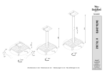
Using Floor Base Plates
1. Determine a mounting location by placing the Shuttle under
the carpet.
2. First, insert the Hexagon bolts (M6 x 25) up through the holes
in the bottom of the floor base plates. The bolt heads should
be recessed into the hole under the base plate so the base lays
flat on the floor. Then, mount the floor base plates to the floor
of the vehicle with the Hexagon flange-head screws (M5 x 15).
3. Cut mat in “+” shape with a knife to allow the threaded shaft
of the floor base plates to come through.
4. Mount the Shuttle on the carpet with hexagon flange-head
nuts (M6).
4
6
5
5
6
5
5
3
4
2
4
1Hexagon Flange-head Screws (M5 x 15)
2“L” Type Brackets (For Horizontal Mounting)
3“L” Type Brackets (For Vertical Mounting)
4Floor Base Plates
5Hexagon Flange-head Nuts (M6)
6Hexagon Bolts (M6 x 25)
3
4
2
4
O.K.
!"
NK !"#$%&'()*$+
OK !"#$%&jSOR !"#$%&'( !"#$%
!"#$%&'()*+(,-./(0 !"#$%&
jRNR !"#$%&' "(
PK !"#$%&'()*!+,-./0
QK !"#$%&jS !"#$%&'(
O.K.
1 !"#$%jRNR
2i= !"#$%&'(
3i= !"#$%&'(
4
5 !"#$%jS
6 !"jSOR
1
=O
Preparation for playback
Before operating the unit, follow the procedure below for loading the CD magazine.
Fig. 1
1. To remove the CD tray 3 from the CD magazine, pull the
lever 2 with your finger (Fig. 1).
2. Insert one disc into each CD tray 3 of the magazine (up to 6
discs ). Make sure the label side of the disc is facing up (Fig. 2)
NOTE:
Hold the disc so you will not leave fingerprints on the disc
surface (refer to "PROPER CARE OF YOUR DISC" section).
When removing the CD tray from the CD magazine, hold the
tray securely so as not to drop the disc.
3. Insert each CD tray, with the disc loaded, all the way into the
CD magazine (Fig. 3).
Be sure to insert 6 CD trays whether the disc is loaded or not.
Make sure the CD trays are inserted straight to prevent jamming (Fig. 4).
4. Open the CD magazine compartment door by sliding it to the
right until it locks. (Fig. 5)
5. Insert the CD magazine 1 all the way into the Shuttle until it
locks with the narrow side facing the unit as shown in Fig. 6.
6. After inserting the CD magazine 1, close the CD magazine
compartment door by sliding it to the left. (Fig. 7)
Caution: Door must be completely closed and remained closed
at all times to prevent dust, water and smoke contaminants from diminishing the overall performance of
the CD Shuttle.
7. To remove the CD magazine, open the CD magazine compartment door, then press the eject button 4. (Fig. 8)
Note: Do not forcibly remove the CD magazine by hand because this would cause damage to the changer
mechanism.
3
=N
Fig. 2
=O
1
Fig. 3
=P
3
Fig. 4
=Q
1
Fig. 6
Fig. 5
=S
=R
4
Fig. 7
=T
Fig. 8
=U
3
!
!"#
2
Proper Handling (Fig. 1)
Handle your disc as shown. Do not drop the disc while handling. Hold the disc
so you will not leave fingerprints on the surface. If the surface is scratched, it
may cause the pickup to skip. Do not affix tape, paper, or gummed labels on
the disc. Do not write on the disc.
!"#=N
!"#$% !"#$ !"#$%&' ()*
!"#$%&'()*+,-. !"#$%&'%!()*+,
!"#$
Caution for new discs (Fig.4)
When a newly purchased disc is inserted into the changer magazine, the disc
may fail to play after initial loading. This is caused by small bumps around the
center hole and outside of the disc, which prevent stable loading into the
correct position. To remove the bumps, rub the inside edge of the hole and
outside edge of the disc with a ball-point pen or other such instrument, then
insert the disc again.
=P
Fig. 3
NOTE:
The mechanism automatically prevents this type of disc from playing as a
protective measure. This is not an indication of faulty operation.
3
3.
2.
Damaged Disc
Do not attempt to play cracked, warped, or otherwise damaged discs.
Playing a bad disc could severely damage the playback mechanism.
1.
!"#$%=O
!"#$%&'()*+,-./012 !"#$%&'()*+
!"#$%& !"#$%&'()*+,-./01234562
!"#=P
!"#$%&'()*+,-./01&'23
!"#$%&'()*+,-./012345$%672)*89:;+
!"#$%&'()*+,sm^JpMMN= !"#$%&'()!#*
!"#$%&'()*+,$-./=sm^JMMN= !"#$%&'(
!"#$%&=Q
!"#$%!&"'()*+,$-!"./0123)4567!"89
!"#$%&&'()*+,-./0123'45 !"#$%&
!"#$%&'()*+,-./012.34567801
!"#$%&'()*+,-./(0123 !"#$%&
!"
!"#$%&'()*+,$-./0123 !"#$%&'()
!"
!"#$%&'()*+,-./'012345678*9:;<
!"#$%&'=R
!"#$%&'()*+,-./ !"#$%& !"#
!"#$%&'(
Storage
When not in use, place your discs in their individual cases and store them
in a cool place away from the sun, heat, and dust.
!"#$%=`a=
NK =`a= =`a=P
!"O
=N
OK !"=`a= !"#$%& !"=S= !" !"
!"#=O
!"#$%&'( )* !"#$%&' `a= =`a= ! !"#$%&'()
PK !"#$%&=`a= !"#=`a==P
!"#$ !=S==`a=
`a= !"#$%&'()*=Q
QK `a= !"#$%&'()*+,=R
RK =`a=N !"#$%&'() !=S
SK =`a=N !"#$% !=T
!"#$%& !"#$%&' !"#$%=`a=
!"#
TK !=`a==`a= !"#$%&Q
=U
!"#$%=`a= !"#$%$&'(
=NJQ
1 !
2 !"#
3 4 Disc Accessories (Fig. 3)
Various disc accessories for protecting the surface of the disc and improving
sound quality are available on the market.
However, many of them will increase the thickness and/or diameter of the disc.
Using such accessories may place the disc beyond the specified size limitations and cause the changer to malfunction. Because of the high precision
electronics of the VPA-S001 and the highly stable mechanism, these accessories are not necessary and therefore not recommended for use with discs
placed in the VPA-S001.
Handling CD magazine/=`a=
English
Refer Fig. 1-4
1 Transparent Sheet
2 Disc Stabilizer
3 Center Hole
4 Bumps
Keep Your Discs Clean (Fig. 2)
Fingerprints, dust, or soil on the surface could cause the pickup to skip. For
routine cleaning, wipe the playing surface with a clean, soft cloth from the
center of the disc to the outer edge. If the surface is heavily soiled, dampen a
clean, soft cloth in a solution of mild neutral detergent before cleaning the disc.
=N
Fig. 1
Fig. 2
2
English
5
4
Fig. 4
=Q
Fig. 5
=R
Irregular Shaped Discs (Fig. 5)
Make sure the discs you use in this unit do not have any irregularities. The
outer and inner edges should be round and smooth. Use of irregularly
shaped discs may cause damage to the mechanism.
Specisications/
English
Sampling Rate ................................................................................................................................................................ 44.1 kHz
System. ..................................................................................................................................... Optical (Compact disc System)
Number of Quantization Bits ................................................................................................................................. 16-bit Linear
Oversampling .................................................................................................................................................................. 8 Times
Number of Channels .................................................................................................................................................... 2 (stereo)
Frequency Response. ........................................................................................................................ 20-20,000 Hz (+0, -0.5 dB)
Wow & Flutter ..................................................................................................................................... Below measurable limits
Total Harmonic Distortion. ................................................................................................................................. 0.1% (at 1 kHz)
Signal-to-Noise Ratio. ...................................................................................................................................................... 80 dBA
Channel Separation ......................................................................................................................... More than 75 dB (at 1 kHz)
Power Requirement .................................................................................................................. 14.4 V DC (11 -16V allowable)
Output Voltage ........................................................................................................................................ 850 mV into 10 kohms
Weight. .......................................................................................................................................................... 1.8 kg (3 lbs. 15 oz)
Dimensions (H x W x D) ..................................................................................................................... 2-3/8" x 9-13/16" x 7-5/8"
...................................................................................................................................................................... (60 x 250 x 193 mm)
NOTE:
Due to product improvement, specifications and design are subject to change without notice.
KKKKKKKKKKKKKKKKKKKKKKKKKKKKKKKKKKKKKKKKKKKKKKKKKKKKKKKKKKKKKKKKKKKKKKKKKKKKKKKKKKKKKKKKKKKKKKKKKKKKKKKKKKKKKKKKKKKKKKKKKKKKKKKKKKKKKKKKKKKKKKKKKKKKKKKKKKKKKKKKKKKKKKKKKKKKKKKKKKKKKKKKKKKKKKKKKKKKKKKKKKKKKKKKK QQKN=heò
KKKKKKKKKKKKKKKKKKKKKKKKKKKKKKKKKKKKKKKKKKKKKKKKKKKKKKKKKKKKKKKKKKKKKKKKKKKKKKKKKKKKKKKKKKKKKKKKKKKKKKKKKKKKKKKKKKKKKKKKKKKKKKKKKKKKKKKKKKKKKKKKKKKKKKKKKKKKKKKKKKKKKKKKKKKKKKKKKKKKKKKKKKKKKKKKKK !
! KKKKKKKKKKKKKKKKKKKKKKKKKKKKKKKKKKKKKKKKKKKKKKKKKKKKKKKKKKKKKKKKKKKKKKKKKKKKKKKKKKKKKKKKKKKKKKKKKKKKKKKKKKKKKKKKKKKKKKKKKKKKKKKKKKKKKKKKKKKKKKKKKKKKKKKKKKKKKKKKKKKKKKKKKKKKKKKKKKKKKKKKKKKKKKKKKKKKKKKK =NS=
! KKKKKKKKKKKKKKKKKKKKKKKKKKKKKKKKKKKKKKKKKKKKKKKKKKKKKKKKKKKKKKKKKKKKKKKKKKKKKKKKKKKKKKKKKKKKKKKKKKKKKKKKKKKKKKKKKKKKKKKKKKKKKKKKKKKKKKKKKKKKKKKKKKKKKKKKKKKKKKKKKKKKKKKKKKKKKKKKKKKKKKKKKKKKKKKKKKKKKKKKKKKKKKKKKKKK U=
KKKKKKKKKKKKKKKKKKKKKKKKKKKKKKKKKKKKKKKKKKKKKKKKKKKKKKKKKKKKKKKKKKKKKKKKKKKKKKKKKKKKKKKKKKKKKKKKKKKKKKKKKKKKKKKKKKKKKKKKKKKKKKKKKKKKKKKKKKKKKKKKKKKKKKKKKKKKKKKKKKKKKKKKKKKKKKKKKKKKKKKKKKKKKKKKKKKKKKKKK O ! KKKKKKKKKKKKKKKKKKKKKKKKKKKKKKKKKKKKKKKKKKKKKKKKKKKKKKKKKKKKKKKKKKKKKKKKKKKKKKKKKKKKKKKKKKKKKKKKKKKKKKKKKKKKKKKKKKKKKKKKKKKKKKKKKKKKKKKKKKKKKKKKKKKKKKKKKKKKKKKKKK OMOMMMM=eòMMKR=Ç_
KKKKKKKKKKKKKKKKKKKKKKKKKKKKKKKKKKKKKKKKKKKKKKKKKKKKKKKKKKKKKKKKKKKKKKKKKKKKKKKKKKKKKKKKKKKKKKKKKKKKKKKKKKKKKKKKKKKKKKKKKKKKKKKKKKKKKKKKKKKKKKKKKKKKKKKKKKKKKKKKKKKKKKKKKKKKKKKKKKKKKKKKKKKKKKKKKKKKKKK !"#
!" KKKKKKKKKKKKKKKKKKKKKKKKKKKKKKKKKKKKKKKKKKKKKKKKKKKKKKKKKKKKKKKKKKKKKKKKKKKKKKKKKKKKKKKKKKKKKKKKKKKKKKKKKKKKKKKKKKKKKKKKKKKKKKKKKKKKKKKKKKKKKKKKKKKKKKKKKKKKKKKKKKKKKKKKKKKKKKKKKKKKK MKNN=âeò=
KKKKKKKKKKKKKKKKKKKKKKKKKKKKKKKKKKKKKKKKKKKKKKKKKKKKKKKKKKKKKKKKKKKKKKKKKKKKKKKKKKKKKKKKKKKKKKKKKKKKKKKKKKKKKKKKKKKKKKKKKKKKKKKKKKKKKKKKKKKKKKKKKKKKKKKKKKKKKKKKKKKKKKKKKKKKKKKKKKKKKKKKKKKKKKKKKKKKKKKKKKKKKKKKKKKK UM=Ç_^
! KKKKKKKKKKKKKKKKKKKKKKKKKKKKKKKKKKKKKKKKKKKKKKKKKKKKKKKKKKKKKKKKKKKKKKKKKKKKKKKKKKKKKKKKKKKKKKKKKKKKKKKKKKKKKKKKKKKKKKKKKKKKKKKKKKKKKKKKKKKKKKKKKKKKKKKKKKKKKKKKKKKKKKKKKKKKKKK =TR=Ç_N=âeò=
! KKKKKKKKKKKKKKKKKKKKKKKKKKKKKKKKKKKKKKKKKKKKKKKKKKKKKKKKKKKKKKKKKKKKKKKKKKKKKKKKKKKKKKKKKKKKKKKKKKKKKKKKKKKKKKKKKKKKKKKKKKKKKKKKKKKKKKKKKKKKKKKKKKKKKKKKKKKKKKKKKKK =NQKQ=sNNNS=s=
! KKKKKKKKKKKKKKKKKKKKKKKKKKKKKKKKKKKKKKKKKKKKKKKKKKKKKKKKKKKKKKKKKKKKKKKKKKKKKKKKKKKKKKKKKKKKKKKKKKKKKKKKKKKKKKKKKKKKKKKKKKKKKKKKKKKKKKKKKKKKKKKKKKKKKKKKKKKKKKKKKKKKKKKKKKKKKKKKKKKKKKKKKKKKKKK URM=ãsNM=h
KKKKKKKKKKKKKKKKKKKKKKKKKKKKKKKKKKKKKKKKKKKKKKKKKKKKKKKKKKKKKKKKKKKKKKKKKKKKKKKKKKKKKKKKKKKKKKKKKKKKKKKKKKKKKKKKKKKKKKKKKKKKKKKKKKKKKKKKKKKKKKKKKKKKKKKKKKKKKKKKKKKKKKKKKKKKKKKKKKKKKKKKKKKKKKKKKKKKKKKKKKKKKKKKKKKKKKKKKK NKU=âÖ
!"#"$% KKKKKKKKKKKKKKKKKKKKKKKKKKKKKKKKKKKKKKKKKKKKKKKKKKKKKKKKKKKKKKKKKKKKKKKKKKKKKKKKKKKKKKKKKKKKKKKKKKKKKKKKKKKKKKKKKKKKKKKKKKKKKKKKKKKKKKKKKKKKKKKKKKKKKKKKKKKKKKKKKKKKKK SMORMNVP=ãã
!"#$%&'()*+,-./01
ALPINE ELECTRONICS, INC.
Tokyo office: 1-1-8 Nishi Gotanda,
Shinagawa-ku, Tokyo 141-8501, Japan
Tel.: (03) 3494-1101
ALPINE ELECTRONICS OF AMERICA, INC.
19145 Gramercy Place, Torrance,
California 90501, U.S.A.
Tel.: 1-800-ALPINE-1 (1-800-257-4631)
ALPINE ELECTRONICS OF CANADA, INC.
Suite 203, 7300 Warden Ave. Markham,
Ontario L3R 9Z6, Canada
Tel.: 1-800-ALPINE-1 (1-800-257-4631)
ALPINE ELECTRONICS OF AUSTRALIA PTY. LTD.
6-8 Fiveways Boulevarde Keysborough,
Victoria 3173, Australia
Tel.: (03) 9769-0000
ALPINE ITALIA S.p.A.
Via C. Colombo 8, 20090 Trezzano Sul
Naviglio MI, Italy
Tel.: 02-48 40 16 24
ALPINE ELECTRONICS FRANCE S.A.R.L.
(RCS PONTOISE B 338 101 280)
98, Rue De La Belle Etoile, Z.I. Paris Nord Il
B.P. 50016 F-95945, Roissy,
Charles De Gaulle Cedex, France
Tel.: 01-48 63 89 89
ALPINE ELECTRONICS OF U.K., LTD.
13 Tanners Drive, Blakelands,
Milton Keynes MK14 5BU, U.K.
Tel.: 01908-61 15 56
ALPINE ELECTRONICS DE ESPAÑA, S.A.
Portal De Gamarra 36, Pabellón 32
01013 Vitoria (Alava)-Apdo. 133, Spain
Tel.: 34-45-283588
ALPINE ELECTRONICS GmbH
Kreuzerkamp 7-11
40878 Ratingen, Germany
Tel.: 02102-45 50