1
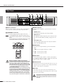
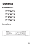
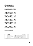
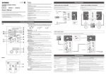
EN
DE
FR
ES
IT
IPA8200 Owner’s Manual
1
RU
Italiano
Español
Français
Deutsch
English
Explanation of Graphical Symbols
The lightning flash with arrowhead symbol
within an equilateral triangle is intended to alert
the user to the presence of uninsulated
“dangerous voltage” within the product’s
enclosure that may be of sufficient magnitude to
constitute a risk of electric shock to persons.
CAUTION
RISK OF ELECTRIC SHOCK
DO NOT OPEN
The exclamation point within an equilateral
triangle is intended to alert the user to the
presence of important operating and maintenance
(servicing) instructions in the literature
accompanying the product.
CAUTION: TO REDUCE THE RISK OF
ELECTRIC SHOCK, DO NOT REMOVE
COVER (OR BACK). NO USER-SERVICEABLE
PARTS INSIDE. REFER SERVICING TO
QUALIFIED SERVICE PERSONNEL.
The above warning is located on the top of the unit.
IMPORTANT SAFETY INSTRUCTIONS
1
2
3
4
5
6
7
8
9
10
Read these instructions.
Keep these instructions.
Heed all warnings.
Follow all instructions.
Do not use this apparatus near water.
Clean only with dry cloth.
Do not block any ventilation openings. Install in
accordance with the manufacturer’s instructions.
Do not install near any heat sources such as radiators,
heat registers, stoves, or other apparatus (including
amplifiers) that produce heat.
Do not defeat the safety purpose of the polarized or
grounding-type plug. A polarized plug has two blades
with one wider than the other. A grounding type plug has
two blades and a third grounding prong. The wide blade
or the third prong are provided for your safety. If the
provided plug does not fit into your outlet, consult an
electrician for replacement of the obsolete outlet.
Protect the power cord from being walked on or pinched
particularly at plugs, convenience receptacles, and the
point where they exit from the apparatus.
11
12
13
14
Only use attachments/accessories specified by the
manufacturer.
Use only with the cart, stand,
tripod, bracket, or table specified
by the manufacturer, or sold with
the apparatus. When a cart is
used, use caution when moving
the cart/apparatus combination to
avoid injury from tip-over.
Unplug this apparatus during
lightning storms or when unused for long periods of
time.
Refer all servicing to qualified service personnel.
Servicing is required when the apparatus has been
damaged in any way, such as power-supply cord or plug
is damaged, liquid has been spilled or objects have
fallen into the apparatus, the apparatus has been
exposed to rain or moisture, does not operate normally,
or has been dropped.
WARNING
TO REDUCE THE RISK OF FIRE OR ELECTRIC SHOCK, DO NOT EXPOSE THIS APPARATUS TO RAIN OR MOISTURE.
(UL60065_03)
FCC INFORMATION (U.S.A.)
1. IMPORTANT NOTICE: DO NOT MODIFY THIS UNIT!
This product, when installed as indicated in the instructions contained in this manual, meets FCC requirements. Modifications not
expressly approved by Yamaha may void your authority, granted by the FCC, to use the product.
2. IMPORTANT: When connecting this product to accessories and/or another product use only high quality shielded cables. Cable/s
supplied with this product MUST be used. Follow all installation instructions. Failure to follow instructions could void your FCC authorization to use this product in the USA.
* This applies only to products distributed by YAMAHA CORPORATION OF AMERICA.
(oscillator)
In Finland: Laite on liitettävä suojamaadoituskoskettimilla varustettuun pistorasiaan.
In Norway: Apparatet må tilkoples jordet stikkontakt.
In Sweden: Apparaten skall anslutas till jordat uttag.
(class1_hokuo)
2
IPA8200 Owner’s Manual
PRECAUTIONS
PLEASE READ CAREFULLY BEFORE PROCEEDING
* Please keep this manual in a safe place for future reference.
WARNING
Always follow the basic precautions listed below to avoid the possibility of serious injury or even death from electrical
shock, short-circuiting, damages, fire or other hazards. These precautions include, but are not limited to, the following:
Power supply/Power cord
Water warning
• Only use the voltage specified as correct for the device. The required voltage is
printed on the name plate of the device.
• Use only the included power cord.
If you intend to use the device in an area other than in the one you purchased,
the included power cord may not be compatible. Please check with your Yamaha
dealer.
• Do not place the power cord near heat sources such as heaters or radiators, and
do not excessively bend or otherwise damage the cord, place heavy objects on
it, or place it in a position where anyone could walk on, trip over, or roll anything
over it.
• Be sure to connect to an appropriate outlet with a protective grounding
connection. Improper grounding can result in electrical shock.
Do not open
• Do not open the device or attempt to disassemble the internal parts or modify
them in any way. The device contains no user-serviceable parts. If it should
appear to be malfunctioning, discontinue use immediately and have it inspected
by qualified Yamaha service personnel.
• Do not expose the device to rain, use it near water or in damp or wet conditions,
or place containers on it containing liquids which might spill into any openings.
If any liquid such as water seeps into the device, turn off the power immediately
and unplug the power cord from the AC outlet. Then have the device inspected
by qualified Yamaha service personnel.
• Never insert or remove an electric plug with wet hands.
If you notice any abnormality
• If the power cord or plug becomes frayed or damaged, or if there is a sudden
loss of sound during use of the device, or if any unusual smells or smoke
should appear to be caused by it, immediately turn off the power switch,
disconnect the electric plug from the outlet, and have the device inspected by
qualified Yamaha service personnel.
• If this device should be dropped or damaged, immediately turn off the power
switch, disconnect the electric plug from the outlet, and have the device
inspected by qualified Yamaha service personnel.
CAUTION
Always follow the basic precautions listed below to avoid the possibility of physical injury to you or others, or damage
to the device or other property. These precautions include, but are not limited to, the following:
• Do not use the device in a confined, poorly-ventilated location. Make sure that
there is adequate space between the device and surrounding walls or other
devices: at least 5cm at the sides, 10cm behind and 10cm above. Inadequate
ventilation can result in overheating, possibly causing damage to the device(s),
or even fire.
Power supply/Power cord
• Remove the electric plug from the outlet when the device is not to be used for
extended periods of time, or during electrical storms.
• When removing the electric plug from the device or an outlet, always hold the
plug itself and not the cord. Pulling by the cord can damage it.
• Do not expose the device to excessive dust or vibrations, or extreme cold or heat
(such as in direct sunlight, near a heater, or in a car during the day) to prevent
the possibility of panel disfiguration or damage to the internal components.
Location
• Before moving the device, remove all connected cables.
• When setting up the device, make sure that the AC outlet you are using is easily
accessible. If some trouble or malfunction occurs, immediately turn off the
power switch and disconnect the plug from the outlet. Even when the power
switch is turned off, electricity is still flowing to the product at the minimum
level. When you are not using the product for a long time, make sure to unplug
the power cord from the wall AC outlet.
• If the device is mounted in an EIA standard rack, carefully read the section
“Precautions when rack-mounting the unit” on page 5. Inadequate ventilation
can result in overheating, possibly causing damage to the device(s),
malfunction, or even fire.
(5)-6
• Do not place the device in an unstable position where it might accidentally fall
over.
• Do not block the vents. This device has ventilation holes at the front and rear to
prevent the internal temperature from becoming too high. In particular, do not
place the device on its side or upside down. Inadequate ventilation can result in
overheating, possibly causing damage to the device(s), or even fire.
• Do not use the device in the vicinity of a TV, radio, stereo equipment, mobile
phone, or other electric devices. Doing so may result in noise, both in the device
itself and in the TV or radio next to it.
• Do not place the device in a location where it may come into contact with
corrosive gases or salt air. Doing so may result in malfunction.
1/2
IPA8200 Owner’s Manual
3
condensation might have occurred, leave the device for several hours without
turning on the power until the condensation has completely dried out.
Connections
• Before connecting the device to other devices, turn off the power for all devices.
Before turning the power on or off for all devices, set all volume levels to
minimum.
• Turn off the power before connecting speakers, and use only the speaker cables
for connecting speakers to the speaker jacks.
Failure to do so can result in fire or electrical shock.
Handling caution
• When turning on the AC power in your audio system, always turn on the device
LAST, to avoid speaker damage. When turning the power off, the device should
be turned off FIRST for the same reason.
• Condensation can occur in the device due to rapid, drastic changes in ambient
temperature – when the device is moved from one location to another, or
airconditioning is turned on or off, for example. Using the device while
condensation is present can cause damage. If there is reason to believe that
• Do not insert your fingers or hands in any gaps or openings on the device
(vents).
• Avoid inserting or dropping foreign objects (paper, plastic, metal, etc.) into any
gaps or openings on the device (vents) If this happens, turn off the power
immediately and unplug the power cord from the AC outlet. Then have the
device inspected by qualified Yamaha service personnel.
• Do not use speakers for a long period of time at a high or uncomfortable volume
level, since this can cause permanent hearing loss. If you experience any
hearing loss or ringing in the ears, consult a physician.
• Do not rest your weight on the device or place heavy objects on it, and avoid use
excessive force on the buttons, switches or connectors.
• Do not use this device for any purpose other than driving loudspeakers.
Yamaha cannot be held responsible for damage caused by improper use or modifications to the device, or data that is lost or destroyed.
Always turn the power off when the device is not in use.
The performance of components with moving contacts, such as switches, volume controls, and connectors, deteriorates over time. Consult qualifi ed Yamaha service
personnel about replacing defective components.
European models
Purchaser/User Information specified in EN55103-1 and EN55103-2.
Inrush Current: 26A
Conforms to Environments: E1, E2, E3 and E4
* Specifications and descriptions in this owner’s manual are for information purposes only. Yamaha Corp. reserves the right to change or modify products or specifications
at any time without prior notice. Since specifications, equipment or options may not be the same in every locale, please check with your Yamaha dealer.
IMPORTANT NOTICE FOR THE UNITED KINGDOM
Connecting the Plug and Cord
WARNING: THIS APPARATUS MUST BE EARTHED
IMPORTANT. The wires in this mains lead are coloured in accordance with the following code:
GREEN-AND-YELLOW : EARTH
BLUE
: NEUTRAL
BROWN
: LIVE
As the colours of the wires in the mains lead of this apparatus may not correspond with the coloured markings identifying the terminals in
your plug proceed as follows:
The wire which is coloured GREEN-and-YELLOW must be connected to the terminal in the plug which is marked by the letter E or by the
safety earth symbol
or colored GREEN or GREEN-and-YELLOW.
The wire which is coloured BLUE must be connected to the terminal which is marked with the letter N or coloured BLACK.
The wire which is coloured BROWN must be connected to the terminal which is marked with the letter L or coloured RED.
• This applies only to products distributed by Yamaha Music U.K. Ltd.
(3 wires)
(5)-6
4
IPA8200 Owner’s Manual
2/2
Introduction
Thank you for purchasing the Yamaha IPA8200 power amplifier.
In order to take full advantage of the IPA8200’s functionality and to ensure trouble-free operation, please read this owner’s manual carefully before use.
After you have read the manual, keep it in a safe place for reference when needed.
Features
■ Space-saving high-efficiency multi-channel 200W@4Ω x 8 power amplifier
■ Switchable between STEREO/PARALLEL/BRIDGE modes as needed for
your application
■ Euroblock input jacks and barrier strip output jacks for easy installation
■ High-pass filter with switchable cutoff frequency (20 Hz / 55 Hz)
■ Input sensitivity / gain select switch switchable between three positions
(+4 dBu, 26 dB, 32 dB)
Precautions when rack-mounting the unit
Operation of this device is guaranteed for an environmental temperature range of 0 – 40°C. If you are mounting
only this device in an EIA standard rack, you may mount multiple units without leaving a space between them. If
you are mounting this device along with other types of device in an EIA standard rack, the ambient temperature
inside the rack may rise due to heat produced from the other devices, preventing this device from performing as
designed. To ensure that heat does not build up inside this device, you must observe the following conditions when
mounting it in a rack.
• If you mount this device in a rack together with heat-generating devices such as power amps made by other companies, you must leave 1U or more space between this device and other devices. You should also install a ventilation panel in this space or leave it open to ensure adequate ventilation.
• Leave the back of the rack open, and allow 10 cm or more distance between the rack and the wall or ceiling to
ensure adequate ventilation. If you are unable to leave the back of the rack open, you must install a commercially
available fan kit or other forced air circulating system to the rack. If you have installed a fan kit, there may be
cases in which closing the back of the rack will provide better cooling. For details, refer to the instructions that
came with the rack system or fan kit.
IPA8200 Owner’s Manual
5
Contents
Introduction............................................................................................................. 5
Features .............................................................................................................. 5
Precautions when rack-mounting the unit ........................................................... 5
Controls and Functions ......................................................................................... 7
Front Panel .......................................................................................................... 7
Rear Panel........................................................................................................... 8
Mode settings ......................................................................................................... 9
STEREO mode.................................................................................................... 9
PARALLEL mode ................................................................................................ 9
BRIDGE mode..................................................................................................... 9
Connections .......................................................................................................... 10
Input jack connections (Euroblock).................................................................... 10
Speaker connections (barrier strip) ................................................................... 10
Troubleshooting ................................................................................................... 11
Specifications ....................................................................................................... 57
General Specifications....................................................................................... 57
Block Diagram ................................................................................................... 58
Dimensions........................................................................................................ 58
Current Draw ..................................................................................................... 59
Accessories (Please make sure the following items are
included in the package.)
• IPA8200 Owner’s Manual (this document)
• Power cable (2.5 m) x 1
• Security cover x 1
• Allen wrench x 1
• Security cover attachment screws x 2
• Euroblock plug (3P) x 8
6
IPA8200 Owner’s Manual
Controls and Functions
Front Panel
Security cover
q POWER switch and indicator
Turns power to the unit on or off. The indicator lights green
when the power is on.
w PROTECT indicator
When the protection system is active, the indicator lights
red. When this is lit, the amplifier or power supply is automatically shut down, and no sound will be output from the
speakers.
e CLIP indicator
This indicator will light red when the output power exceeds
100 W for an 8Ω load or 200 W for a 4Ω load. When this is
lit, the limiter will automatically operate.
r SIGNAL indicator
This indicator will light green when the output level exceeds
2 Vrms. (This will light at 0.5 W or greater for an 8Ω load,
1W or greater for a 4Ω load.)
t Attenuator
These are detented knobs that attenuate the input signal of
each channel (A–H) over 41 steps in a range of 0 dB – –∞
dB.
NOTE
• To operate these knobs, use a slotted screwdriver with
a blade no wider than 5.5 mm.
y MUTE indicator
This will light red when mute is activated.
u MUTE switch
This turns muting on/off for each channel. Use a thin rod to
turn muting on/off.
i PARALLEL indicator
This will light orange when the rear panel MODE switch is
set to PARALLEL.
o BRIDGE indicator
This will light orange when the rear panel MODE switch is
set to BRIDGE.
!0 Screw holes for security cover
If desired, you can use these two screw holes for attaching
the included security cover to prevent the attenuator setting
from being changed. Use the included Allen wrench and
screws to attach the cover.
!1 Air intakes
The amplifier uses forced-air cooling. The variable speed
cooling fan draws air in from the front and exhausts it
through the rear. The cooling fan operates at low speed when
the heat sink temperature is below 65 °C (149 °F), or at high
speed when the temperature exceeds 65 °C (140 °F). Please
be sure that you do not block the air intakes or exhaust vents.
IPA8200 Owner’s Manual
7
Controls and Functions
Rear Panel
q
e
q INPUT connectors
These are balanced input connectors. The included Euroblock connectors can be used to make connections here.
w SPEAKERS connectors
These are barrier strip type speaker output connectors.
NOTE
• If using BRIDGE mode, connect the speakers to the “+”
pin of channels A/C/E/G and the “–” pin of channels B/
D/F/H.
• Do not connect the pin marked NC located in the center
of the bottom row of the barrier strip connectors.
w
r
t
y
u
e MODE switches
These specify the amplifier’s operation mode for each two
channels.
• STEREO mode
Each channel (A–H) will operate independently.
• BRIDGE mode
The amplifiers will be bridged for pairs of adjacent channels (A-B, C-D, E-F, G-H), obtaining a high-power output.
• PARALLEL mode
The input signals will be input to the adjacent channels
(A-B, C-D, E-F, G-H) as well.
r GAIN switch
This switches the input sensitivity / gain for all channels
together.
• +4 dBu: Sets the input sensitivity to +4 dBu.
Caution regarding output measurement
CAUTION
• To make the load to the power supply consistent and in
particular to improve frequency response in the low
range at very high volumes, channels B/D/F/H have
been designed so that the signal is reversed in polarity
just before the power amp stage and then output to the
“-” pins of the corresponding SPEAKER terminals.
(See the Block Diagram.)
If you measure the output, we recommend that you use
an instrument that is compatible with balanced input. If
you have an instrument that is compatible only with
unbalanced input, use the “+” pin of channels B/D/F/H
as ground, and apply a probe to the “-” pin and measure the output carefully. Using the probe improperly
may cause the amplifier or instrument to malfunction.
• 26 dB:
Sets the gain to 26 dB.
• 32 dB:
Sets the gain to 32 dB.
t HPF switch
Turns the high pass filter (20 Hz or 55 Hz) on/off. If this is
set to 20 Hz or 55 Hz, the frequency components below that
frequency will be cut by a 12 dB/oct. filter.
y Ground screw
Hum and interference may be reduced in some cases by connecting the screw to an ground or to the chassis of the mixer,
preamp, or other device in your system.
u AC inlet
Connect this to the socket end of the included AC power
cable . Connect the plug end of the AC power cable to an AC
outlet of the correct voltage.
CAUTION
8
IPA8200 Owner’s Manual
• If this device is to be rack mounted and transported
frequently, be sure to support the rear end of the unit
with mounting hardware that matches the size of the
rack used.
Mode settings
Speakers can be connected to the IPA8200 using the following three mode settings. The total load impedance of
the speakers that can be connected will depend on the mode setting. Do not use a setup that has a lower impedance
than the minimum values shown below.
STEREO mode
BRIDGE mode
If the rear panel MODE switch is set to STEREO, each channel will operate independently. You can use the front panel
attenuators to adjust the attenuation for each channel independently.
If the rear panel MODE switch is set to BRIDGE, the amplifiers will be bridged between adjacent pairs of channels (AB, C-D, E-F, G-H), and the IPA8200 will operate as a highpower amplifier. Either of adjacent two channels can be used
as an input connector. Use the front panel channel A/C/E/G
attenuators to adjust the attenuation.
NOTE
• If using BRIDGE mode, connect the speakers to the “+”
pin of channels A/C/E/G and the “–” pin of channels B/
D/F/H.
• Total speaker impedance must be 8–16Ω.
Source:
Channel B
NOTE
Source:
Channel A
Total speaker
impedance: 4–8Ω
• Total speaker impedance must be 4–8Ω.
PARALLEL mode
If the rear panel MODE switch is set to PARALLEL, the
input signals will be input to the adjacent channels (A-B, CD, E-F, G-H) as well. Either of adjacent two channels can be
used as an input connector. You can use the front panel attenuators to adjust the attenuation for each channel independently.
Source:
Channel A
NOTE
Source:
Channel A
Source:
Channel A
Total speaker
impedance: 8–16Ω
Total speaker
impedance: 4–8Ω
• Total speaker impedance must be 4–8Ω.
IPA8200 Owner’s Manual
9
Connections
Input jack connections (Euroblock)
Please be sure to use the supplied Euroblock connectors.
If you lose them, contact your nearest Yamaha dealer.
● Cable preparation
• To prepare the cable for attachment to a Euroblock connector, strip the wire as shown in the illustration, and use
stranded wire to make connections. With a Euroblock
connection, the stranded wire may be prone to breakage
because of metal fatigue due to the weight of the cable or
due to vibration. When rack-mounting your equipment,
use a lacing bar when possible to bundle and fasten the
cables.
Speaker connections (barrier strip)
If using a spade lug
From below, insert the spade lug all the way, and tighten the
screw.
approx.
7 mm
1.6 mm
or less
approx.
7 mm
• If you use stranded wire, do not tin (plate
with solder) the exposed end.
CAUTION
If using a bare conductor
Wrap the conductor around the barrier strip terminal as
shown below, and tighten the screw. Be sure that the bare
wire does not touch the chassis.
15mm*
• If cables will be frequently connected and disconnected,
as in the case of a portable installation, we recommend
that you use ferrules with insulation sleeves. Use a ferrule
whose conductor portion has an external diameter of 1.6
mm or less, and a length of approximately 7 mm (such as
the AI0, 5-6WH made by the Phoenix Contact corporation).
1. If the wire insertion ports are closed, turn the screws on
top of the connector counterclockwise to open the
ports.
2. Insert the wires into the appropriate ports, following
Wire should
not touch
the chassis.
* Actual size
the indication of the pole on the input terminal, and
turn the screws on top of the connector clockwise to
fasten the wires.
3. Connect the Euroblock connector to the IPA8200’s
input jack.
Use a slotted screwdriver
to fix the wires.
Wires
Euroblock connector
+
10
IPA8200 Owner’s Manual
–
G
NOTE
Speaker
cable
• Do not connect the pin marked NC located in the center
of the bottom row of the barrier strip connectors.
• If using BRIDGE mode, connect the speakers to the “+”
pin of channels A/C/E/G and the “–” pin of channels B/
D/F/H.
Troubleshooting
Indicator(s)
Possible cause
Remedy
Protection circuit
CLIP indicator is
lit.
Output exceeds 100 W
(8Ω) or 200 W (4Ω).
Lower the input level.
Limiter circuit will operate
to protect the power amp
and power supply.
PROTECT indicator is lit.
Speaker output connector is shorted.
Check whether the speaker output connector or speaker cable could be shorted,
and then power-cycle the IPA8200.
If the PROTECT indicator is still lit, contact your Yamaha dealer.
The protection circuit will
operate to project the
power amp and power
supply.
The power amp section’s
heat sink temperature has
exceeded 95°C or the
power supply section’s
heat sink temperature has
exceeded 85°C.
Check whether there might be blockage
at the air intake or a ventilation problem
inside the rack, and verify that the load
impedance of the connected speakers is
not below the rated value (4Ω or 8Ω/
BRIDGE).
Then wait until the unit’s temperature has
dropped, and power-cycle the unit.
If the PROTECT indicator is still lit, contact your Yamaha dealer.
The protection circuit will
operate to protect the
power amp.
A DC offset voltage is
being output to the
speaker output connector.
Consult your Yamaha dealer.
The protection circuit will
operate to protect the
speakers.
IPA8200 Owner’s Manual
11
Specifications
General Specifications
Output Power
1kHz, THD+N=1%
20Hz-20kHz, THD+N=1%
1kHz, 20ms Burst
4Ω per channel
200W x 8
8Ω per channel
100W x 8
8Ω / BRIDGE
400W x 4
4Ω per channel
180W x 8
8Ω per channel
90W x 8
8Ω / BRIDGE
360W x 4
4Ω per channel
200W x 8
8Ω per channel
100W x 8
8Ω / BRIDGE
400W x 4
Maximum Input Level
+24dBu
20kΩ(balanced), 10kΩ(unbalanced)
Input Impedance
Input Sensitivity (dBu)
8Ω, Att. max
Voltage Gain
Att. Max
Switch Position
+4dBu
26dB
32dB
Input sensitivity
+4dBu
+5.2dBu
–0.8dBu
Switch Position
+4dBu
26dB
32dB
Voltage Gain
27.2dB
26dB
32dB
≥100dB
S/N Ratio
A-weighted
THD+N
1kHz, half power, 4Ω
Frequency Response
1W, 8Ω
Channel Separation
1kHz, half power, 8 Ω
Att. max, input 600Ω shunt
Controls
Front Panel
POWER switch (rocker)
MUTE switch (push ON/push OFF) x 8
Attenuator (41positon) x 8
Rear Panel
MODE switch (STEREO/BRIDGE/PARALLEL) x 4
GAIN switch (+4dBu/26dB/32dB) x 1
HPF switch (OFF/20Hz/55Hz) x 1
Connectors
≤0.5%
20Hz-20kHz, +0dB, –1.5dB
≥60dB
Input
Euroblock (balanced)/ch
Output
Barrier strip/ch
Power
Indicators
Load Protection
Amplifier Protection
AC inlet x 1
POWER x 1 (Green), PROTECT x 8 (Red),
CLIP x 8 (Red), SIGNAL x 8 (Green), MUTE x 8 (Red),
PARALLEL x 4 (Orange), BRIDGE x 4 (Orange)
POWER switch on/off
Output mute
DC-fault
Power supply shutdown
Thermal
Output mute (heatsink temp ≥95˚C)
Over current
Power Supply Protection
Thermal
Limiter Circuit
Clip limiting
Power supply shutdown
Power supply shutdown (heatsink temp ≥85˚C)
Limiting level ≥100W@8Ω or 200W@4Ω
Cooling
High/Low two speed fan x 2
AC Power Requirement
U.S./Canada: 120V, 60Hz
Korea: 220V, 60Hz
China: 220V, 50Hz
Other: 220V-240V, 50/60Hz
Power Consumption
Dimensions (W x H x D)
400W
480 x 88 x 406.5mm (18-7/8 x 3-7/16 x 16 inch)
(The depth is measured from the front panel surface to the
rear mounting hardware.)
Weight
Included Accessories
10.5kg (23.2 lbs)
AC power cord (2.5m) x 1, Security cover x 1,
Allen wrench x 1, Security cover attachment screw x 2,
3-pin Euroblock connector x 8, Owner’s manual
• Half power = 3dB below rated power
• 0dBu = 0.775Vrms
• Specifications and descriptions in this owner’s manual are for information purposes only. Yamaha Corp. reserves the right to change or modify
products or specifications at any time without prior notice. Since specifications, equipment or options may not be the same in every locale, please
check with your Yamaha dealer.
Before you measure the output, refer to the cautions on the following page:
English: p.8 / German: p.17 / French: p.26 / Spanish: p.35 / Italian: p.44 / Russian: p.53
IPA8200 Owner’s Manual
57
Specifications
CH A, C, E, G
Block Diagram
+
–
G
HPF
Fc=20Hz
+
–
Comp.
GAIN
ATTENUATOR MUTE
HA
HPF
Fc=20Hz
G
HPF
Fc=55Hz
BA
STEREO MODE
BRIDGE
PARALLEL
HPF
Fc=55Hz
STEREO
BRIDGE
PARALLEL
CH B, D, F, H
HPF
ATTENUATOR MUTE
HA
STEREO MODE
BRIDGE
PARALLEL
Clip Level
Detect
P.Amp
Signal Level
Detect
Output
Filter SPEAKERS
–
+ A, C, E, G
–
+ B, D, F, H
Comp.
BA
Level
Detect
Inv
P.Amp
Signal Level
Detect
HPF
GAIN
406.5 (16")
377.7 (14-7/8")
Dimensions
88 (3-7/16")
480 (18-7/8")
58
IPA8200 Owner’s Manual
Unit: mm (inch)
Specifications
Current Draw
Idle
1/8 power
1/3 power
8Ω/ch
4Ω/ch
8Ω/ch
4Ω/ch
Line Current (A)
100/120V
230/240V
0.8
0.4
1.9
1.0
3.3
1.5
3.9
1.8
7.7
3.3
In
69
189
327
389
774
Power (W)
Out
0
100
200
267
533
Dissipated
69
89
127
122
241
Thermal Dissipation
Btu/h
kcal/h
235
59
304
77
433
109
417
105
821
207
1/8 power is typical of program material with occasional clipping. Refer to these figures for most applications.
1/3 power represents program material with extremely heavy clipping.
Test signal: Pink Noise, bandwidth limited from 22Hz to 22kHz
1W = 0.860kcal/h, 1BTU = 0.252kcal
Note that Line Voltage [V] x Line Current [A] = [VA], not equals to [W].
Inrush current: 11A (100V), 13A (120V), 26A (240V)
IPA8200 Owner’s Manual
59
MEMO
60
IPA8200 Owner’s Manual
EN
Information for Users on Collection and Disposal of Old Equipment
This symbol on the products, packaging, and/or accompanying documents means that used electrical and electronic products
should not be mixed with general household waste.
For proper treatment, recovery and recycling of old products, please take them to applicable collection points, in accordance
with your national legislation and the Directives 2002/96/EC.
By disposing of these products correctly, you will help to save valuable resources and prevent any potential negative effects on
human health and the environment which could otherwise arise from inappropriate waste handling.
For more information about collection and recycling of old products, please contact your local municipality, your waste disposal
service or the point of sale where you purchased the items.
[For business users in the European Union]
If you wish to discard electrical and electronic equipment, please contact your dealer or supplier for further information.
[Information on Disposal in other Countries outside the European Union]
This symbol is only valid in the European Union. If you wish to discard these items, please contact your local authorities or
dealer and ask for the correct method of disposal.
DE
Verbraucherinformation zur Sammlung und Entsorgung alter Elektrogeräte
Befindet sich dieses Symbol auf den Produkten, der Verpackung und/oder beiliegenden Unterlagen, so sollten benutzte elektrische Geräte nicht mit dem normalen Haushaltsabfall entsorgt werden.
In Übereinstimmung mit Ihren nationalen Bestimmungen und den Richtlinien 2002/96/EC, bringen Sie alte Geräte bitte zur
fachgerechten Entsorgung, Wiederaufbereitung und Wiederverwendung zu den entsprechenden Sammelstellen.
Durch die fachgerechte Entsorgung der Elektrogeräte helfen Sie, wertvolle Ressourcen zu schützen und verhindern mögliche
negative Auswirkungen auf die menschliche Gesundheit und die Umwelt, die andernfalls durch unsachgerechte Müllentsorgung auftreten könnten.
Für weitere Informationen zum Sammeln und Wiederaufbereiten alter Elektrogeräte, kontaktieren Sie bitte Ihre örtliche Stadtoder Gemeindeverwaltung, Ihren Abfallentsorgungsdienst oder die Verkaufsstelle der Artikel.
[Information für geschäftliche Anwender in der Europäischen Union]
Wenn Sie Elektrogeräte ausrangieren möchten, kontaktieren Sie bitte Ihren Händler oder Zulieferer für weitere Informationen.
[Entsorgungsinformation für Länder außerhalb der Europäischen Union]
Dieses Symbol gilt nur innerhalb der Europäischen Union. Wenn Sie solche Artikel ausrangieren möchten, kontaktieren Sie
bitte Ihre örtlichen Behörden oder Ihren Händler und fragen Sie nach der sachgerechten Entsorgungsmethode.
FR
Information concernant la Collecte et le Traitement des déchets d’équipements
électriques et électroniques
Le symbole sur les produits, l’emballage et/ou les documents joints signifie que les produits électriques ou électroniques usagés ne doivent pas être mélangés avec les déchets domestiques habituels.
Pour un traitement, une récupération et un recyclage appropriés des déchets d’équipements électriques et électroniques,
veuillez les déposer aux points de collecte prévus à cet effet, conformément à la réglementation nationale et aux Directives
2002/96/EC.
En vous débarrassant correctement des déchets d’équipements électriques et électroniques, vous contribuerez à la sauvegarde de précieuses ressources et à la prévention de potentiels effets négatifs sur la santé humaine qui pourraient advenir lors
d’un traitement inapproprié des déchets.
Pour plus d’informations à propos de la collecte et du recyclage des déchets d’équipements électriques et électroniques,
veuillez contacter votre municipalité, votre service de traitement des déchets ou le point de vente où vous avez acheté les produits.
[Pour les professionnels dans l’Union Européenne]
Si vous souhaitez vous débarrasser des déchets d’équipements électriques et électroniques veuillez contacter votre vendeur
ou fournisseur pour plus d’informations.
[Information sur le traitement dans d’autres pays en dehors de l’Union Européenne]
Ce symbole est seulement valables dans l’Union Européenne. Si vous souhaitez vous débarrasser de déchets d’équipements
électriques et électroniques, veuillez contacter les autorités locales ou votre fournisseur et demander la méthode de traitement
appropriée.
IPA8200 Owner’s Manual
61
ES
Información para Usuarios sobre Recolección y Disposición de Equipamiento Viejo
Este símbolo en los productos, embalaje, y/o documentación que se acompañe significa que los productos electrónicos y eléctricos usados no deben ser mezclados con desechos hogareños corrientes.
Para el tratamiento, recuperación y reciclado apropiado de los productos viejos, por favor llévelos a puntos de recolección aplicables, de acuerdo a su legislación nacional y las directivas 2002/96/EC.
Al disponer de estos productos correctamente, ayudará a ahorrar recursos valiosos y a prevenir cualquier potencial efecto
negativo sobre la salud humana y el medio ambiente, el cual podría surgir de un inapropiado manejo de los desechos.
Para mayor información sobre recolección y reciclado de productos viejos, por favor contacte a su municipio local, su servicio
de gestión de residuos o el punto de venta en el cual usted adquirió los artículos.
[Para usuarios de negocios en la Unión Europea]
Si usted desea deshacerse de equipamiento eléctrico y electrónico, por favor contacte a su vendedor o proveedor para mayor
información.
[Información sobre la Disposición en otros países fuera de la Unión Europea]
Este símbolo sólo es válidos en la Unión Europea. Si desea deshacerse de estos artículos, por favor contacte a sus autoridades locales y pregunte por el método correcto de disposición.
IT
Informazioni per gli utenti sulla raccolta e lo smaltimento di vecchia attrezzatura
Questo simbolo sui prodotti, sull’imballaggio, e/o sui documenti che li accompagnano significa che i prodotti elettriche e elettroniche non dovrebbero essere mischiati con i rifiuti domestici generici.
Per il trattamento, recupero e riciclaggio appropriati di vecchi prodotti, li porti, prego, ai punti di raccolta appropriati, in accordo
con la Sua legislazione nazionale e le direttive 2002/96/CE.
Smaltendo correttamente questi prodotti, Lei aiuterà a salvare risorse preziose e a prevenire alcuni potenziali effetti negativi
sulla salute umana e l’ambiente, che altrimenti potrebbero sorgere dal trattamento improprio dei rifiuti.
Per ulteriori informazioni sulla raccolta e il riciclaggio di vecchi prodotti, prego contatti la Sua amministrazione comunale locale,
il Suo servizio di smaltimento dei rifiuti o il punto vendita dove Lei ha acquistato gli articoli.
[Per utenti imprenditori dell’Unione europea]
Se Lei desidera disfarsi di attrezzatura elettrica ed elettronica, prego contatti il Suo rivenditore o fornitore per ulteriori informazioni.
[Informazioni sullo smaltimento negli altri Paesi al di fuori dell’Unione europea]
Questo simbolo è validi solamente nell’Unione europea. Se Lei desidera disfarsi di questi articoli, prego contatti le Sue autorità
locali o il rivenditore e richieda la corretta modalità di smaltimento.
62
IPA8200 Owner’s Manual
For details of products, please contact your nearest Yamaha
representative or the authorized distributor listed below.
Para detalles sobre productos, contacte su tienda Yamaha más cercana
o el distribuidor autorizado que se lista debajo.
Die Einzelheiten zu Produkten sind bei Ihrer unten aufgeführten
Niederlassung und bei Yamaha Vertragshändlern in den jeweiligen
Bestimmungsländern erhältlich.
Per ulteriori dettagli sui prodotti, rivolgersi al più vicino rappresentante
Yamaha oppure a uno dei distributori autorizzati elencati di seguito.
Pour plus de détails sur les produits, veuillez-vous adresser à Yamaha ou
au distributeur le plus proche de vous figurant dans la liste suivante.
NORTH AMERICA
CANADA
Yamaha Canada Music Ltd.
135 Milner Avenue, Scarborough, Ontario,
M1S 3R1, Canada
Tel: 416-298-1311
U.S.A.
Yamaha Corporation of America
6600 Orangethorpe Ave., Buena Park, Calif. 90620,
U.S.A.
Tel: 714-522-9011
CENTRAL & SOUTH AMERICA
MARTA
Olimpus Music Ltd.
The Emporium, Level 3, St. Louis Street Msida
MSD06
Tel: 02133-2144
THE NETHERLANDS/
BELGIUM/LUXEMBOURG
Yamaha Music Europe Branch Benelux
Clarissenhof 5-b, 4133 AB Vianen, The Netherlands
Tel: 0347-358 040
FRANCE
Yamaha Music Europe
BP 70-77312 Marne-la-Vallée Cedex 2, France
Tel: 01-64-61-4000
ITALY
MEXICO
Yamaha de México S.A. de C.V.
Calz. Javier Rojo Gómez #1149,
Col. Guadalupe del Moral
C.P. 09300, México, D.F., México
Tel: 55-5804-0600
BRAZIL
Yamaha Musical do Brasil Ltda.
Rua Joaquim Floriano, 913 - 4' andar, Itaim Bibi,
CEP 04534-013 Sao Paulo, SP. BRAZIL
Tel: 011-3704-1377
ARGENTINA
Yamaha Music Latin America, S.A.
Sucursal de Argentina
Olga Cossettini 1553, Piso 4 Norte
Madero Este-C1107CEK
Buenos Aires, Argentina
Tel: 011-4119-7000
PANAMA AND OTHER LATIN
AMERICAN COUNTRIES/
CARIBBEAN COUNTRIES
Yamaha Music Latin America, S.A.
Torre Banco General, Piso 7, Urbanización Marbella,
Calle 47 y Aquilino de la Guardia,
Ciudad de Panamá, Panamá
Tel: +507-269-5311
EUROPE
THE UNITED KINGDAM/IRELAND
Yamaha Music Europe GmbH (UK)
Sherbourne Drive, Tilbrook, Milton Keynes,
MK7 8BL, England
Tel: 01908-366700
GERMANY
Yamaha Music Europe GmbH
Siemensstraße 22-34, 25462 Rellingen, Germany
Tel: 04101-3030
SWITZERLAND/LIECHTENSTEIN
Yamaha Music Europe GmbH
Branch Switzerland in Zürich
Seefeldstrasse 94, 8008 Zürich, Switzerland
Tel: 044-387-8080
AUSTRIA/BULGARIA
Yamaha Music Europe GmbH Branch Austria
Schleiergasse 20, A-1100 Wien, Austria
Tel: 01-60203900
CZECH REPUBLIC/HUNGARY/
ROMANIA/SLOVAKIA/SLOVENIA
Yamaha Music Europe GmbH
Branch Austria (Central Eastern Europe Office)
Schleiergasse 20, A-1100 Wien, Austria
Tel: 01-602039025
POLAND/LITHUANIA/LATVIA/ESTONIA
Yamaha Music Europe GmbH
Branch Sp.z o.o. Oddzial w Polsce
ul. 17 Stycznia 56, PL-02-146 Warszawa, Poland
Tel: 022-500-2925
Yamaha Music Europe GmbH, Branch Italy
Viale Italia 88, 20020 Lainate (Milano), Italy
Tel: 02-935-771
SPAIN/PORTUGAL
Yamaha Music Europe GmbH Ibérica, Sucursal
en España
Ctra. de la Coruna km. 17, 200, 28230
Las Rozas (Madrid), Spain
Tel: +34-902-39-8888
GREECE
Philippos Nakas S.A. The Music House
147 Skiathou Street, 112-55 Athens, Greece
Tel: 01-228 2160
SWEDEN/FINLAND/ICELAND
Yamaha Music Europe GmbH Germany filial
Scandinavia
J. A. Wettergrens Gata 1, Box 30053
S-400 43 Göteborg, Sweden
Tel: 031 89 34 00
DENMARK
Yamaha Music Europe GmbH, Tyskland – filial
Denmark
Generatorvej 6A, DK-2730 Herlev, Denmark
Tel: 44 92 49 00
NORWAY
Yamaha Music Europe GmbH Germany Norwegian Branch
Grini Næringspark 1, N-1345 Østerås, Norway
Tel: 67 16 77 70
RUSSIA
Yamaha Music (Russia)
Room 37, bld. 7, Kievskaya street, Moscow,
121059, Russia
Tel: 495 626 5005
OTHER EUROPEAN COUNTRIES
Yamaha Music Europe GmbH
Siemensstraße 22-34, 25462 Rellingen, Germany
Tel: +49-4101-3030
AFRICA
Yamaha Corporation,
Asia-Pacific Sales & Marketing Group
Nakazawa-cho 10-1, Naka-ku, Hamamatsu,
Japan 430-8650
Tel: +81-53-460-2303
MIDDLE EAST
TURKEY/CYPRUS
ASIA
THE PEOPLE’S REPUBLIC OF CHINA
Yamaha Music & Electronics (China) Co.,Ltd.
2F, Yunhedasha, 1818 Xinzha-lu, Jingan-qu,
Shanghai, China
Tel: 021-6247-2211
INDIA
Yamaha Music India Pvt. Ltd.
5F Ambience Corporate Tower Ambience Mall Complex
Ambience Island, NH-8, Gurgaon-122001, Haryana, India
Tel: 0124-466-5551
INDONESIA
PT. Yamaha Musik Indonesia (Distributor)
PT. Nusantik
Gedung Yamaha Music Center, Jalan Jend. Gatot
Subroto Kav. 4, Jakarta 12930, Indonesia
Tel: 021-520-2577
KOREA
Yamaha Music Korea Ltd.
8F, 9F, Dongsung Bldg. 158-9 Samsung-Dong,
Kangnam-Gu, Seoul, Korea
Tel: 02-3467-3300
MALAYSIA
Yamaha Music (Malaysia) Sdn., Bhd.
Lot 8, Jalan Perbandaran, 47301 Kelana Jaya,
Petaling Jaya, Selangor, Malaysia
Tel: 03-78030900
SINGAPORE
Yamaha Music (Asia) Pte., Ltd.
#03-11 A-Z Building
140 Paya Lebor Road, Singapore 409015
Tel: 6747-4374
TAIWAN
Yamaha KHS Music Co., Ltd.
3F, #6, Sec.2, Nan Jing E. Rd. Taipei.
Taiwan 104, R.O.C.
Tel: 02-2511-8688
THAILAND
Siam Music Yamaha Co., Ltd.
4, 6, 15 and 16th floor, Siam Motors Building,
891/1 Rama 1 Road, Wangmai,
Pathumwan, Bangkok 10330, Thailand
Tel: 02-215-2622
OTHER ASIAN COUNTRIES
Yamaha Corporation,
Asia-Pacific Sales & Marketing Group
Nakazawa-cho 10-1, Naka-ku, Hamamatsu,
Japan 430-8650
Tel: +81-53-460-2303
OCEANIA
AUSTRALIA
Yamaha Music Australia Pty. Ltd.
Level 1, 99 Queensbridge Street, Southbank,
Victoria 3006, Australia
Tel: 3-9693-5111
COUNTRIES AND TRUST
TERRITORIES IN PACIFIC OCEAN
Yamaha Corporation,
Asia-Pacific Sales & Marketing Group
Nakazawa-cho 10-1, Naka-ku, Hamamatsu,
Japan 430-8650
Tel: +81-53-460-2303
Yamaha Music Europe GmbH
Siemensstraße 22-34, 25462 Rellingen, Germany
Tel: 04101-3030
OTHER COUNTRIES
Yamaha Music Gulf FZE
LOB 16-513, P.O.Box 17328, Jubel Ali,
Dubai, United Arab Emirates
Tel: +971-4-881-5868
HEAD OFFICE Yamaha Corporation, Pro Audio Division
Nakazawa-cho 10-1, Naka-ku, Hamamatsu, Japan 430-8650
Tel: +81-53-460-2441
PA29
IPA8200 Owner’s Manual
63
Yamaha Pro Audio global web site:
http://www.yamahaproaudio.com/
Yamaha Manual Library
http://www.yamaha.co.jp/manual/
C.S.G., Pro Audio Division
© 2009-2011 Yamaha Corporation
109PO-04D0